JP2005299536A - Variable valve operating device for internal combustion engine - Google Patents
Variable valve operating device for internal combustion engine Download PDFInfo
- Publication number
- JP2005299536A JP2005299536A JP2004117812A JP2004117812A JP2005299536A JP 2005299536 A JP2005299536 A JP 2005299536A JP 2004117812 A JP2004117812 A JP 2004117812A JP 2004117812 A JP2004117812 A JP 2004117812A JP 2005299536 A JP2005299536 A JP 2005299536A
- Authority
- JP
- Japan
- Prior art keywords
- arm
- internal combustion
- combustion engine
- valve
- intake
- Prior art date
- Legal status (The legal status is an assumption and is not a legal conclusion. Google has not performed a legal analysis and makes no representation as to the accuracy of the status listed.)
- Granted
Links
Images

Classifications
-
- F—MECHANICAL ENGINEERING; LIGHTING; HEATING; WEAPONS; BLASTING
- F01—MACHINES OR ENGINES IN GENERAL; ENGINE PLANTS IN GENERAL; STEAM ENGINES
- F01L—CYCLICALLY OPERATING VALVES FOR MACHINES OR ENGINES
- F01L13/00—Modifications of valve-gear to facilitate reversing, braking, starting, changing compression ratio, or other specific operations
- F01L13/0015—Modifications of valve-gear to facilitate reversing, braking, starting, changing compression ratio, or other specific operations for optimising engine performances by modifying valve lift according to various working parameters, e.g. rotational speed, load, torque
- F01L13/0063—Modifications of valve-gear to facilitate reversing, braking, starting, changing compression ratio, or other specific operations for optimising engine performances by modifying valve lift according to various working parameters, e.g. rotational speed, load, torque by modification of cam contact point by displacing an intermediate lever or wedge-shaped intermediate element, e.g. Tourtelot
-
- F—MECHANICAL ENGINEERING; LIGHTING; HEATING; WEAPONS; BLASTING
- F01—MACHINES OR ENGINES IN GENERAL; ENGINE PLANTS IN GENERAL; STEAM ENGINES
- F01L—CYCLICALLY OPERATING VALVES FOR MACHINES OR ENGINES
- F01L1/00—Valve-gear or valve arrangements, e.g. lift-valve gear
- F01L1/02—Valve drive
- F01L1/04—Valve drive by means of cams, camshafts, cam discs, eccentrics or the like
-
- F—MECHANICAL ENGINEERING; LIGHTING; HEATING; WEAPONS; BLASTING
- F01—MACHINES OR ENGINES IN GENERAL; ENGINE PLANTS IN GENERAL; STEAM ENGINES
- F01L—CYCLICALLY OPERATING VALVES FOR MACHINES OR ENGINES
- F01L1/00—Valve-gear or valve arrangements, e.g. lift-valve gear
- F01L1/12—Transmitting gear between valve drive and valve
- F01L1/18—Rocking arms or levers
- F01L1/181—Centre pivot rocking arms
-
- F—MECHANICAL ENGINEERING; LIGHTING; HEATING; WEAPONS; BLASTING
- F01—MACHINES OR ENGINES IN GENERAL; ENGINE PLANTS IN GENERAL; STEAM ENGINES
- F01L—CYCLICALLY OPERATING VALVES FOR MACHINES OR ENGINES
- F01L1/00—Valve-gear or valve arrangements, e.g. lift-valve gear
- F01L1/12—Transmitting gear between valve drive and valve
- F01L1/18—Rocking arms or levers
- F01L1/185—Overhead end-pivot rocking arms
-
- F—MECHANICAL ENGINEERING; LIGHTING; HEATING; WEAPONS; BLASTING
- F01—MACHINES OR ENGINES IN GENERAL; ENGINE PLANTS IN GENERAL; STEAM ENGINES
- F01L—CYCLICALLY OPERATING VALVES FOR MACHINES OR ENGINES
- F01L1/00—Valve-gear or valve arrangements, e.g. lift-valve gear
- F01L1/26—Valve-gear or valve arrangements, e.g. lift-valve gear characterised by the provision of two or more valves operated simultaneously by same transmitting-gear; peculiar to machines or engines with more than two lift-valves per cylinder
- F01L1/267—Valve-gear or valve arrangements, e.g. lift-valve gear characterised by the provision of two or more valves operated simultaneously by same transmitting-gear; peculiar to machines or engines with more than two lift-valves per cylinder with means for varying the timing or the lift of the valves
-
- F—MECHANICAL ENGINEERING; LIGHTING; HEATING; WEAPONS; BLASTING
- F01—MACHINES OR ENGINES IN GENERAL; ENGINE PLANTS IN GENERAL; STEAM ENGINES
- F01L—CYCLICALLY OPERATING VALVES FOR MACHINES OR ENGINES
- F01L1/00—Valve-gear or valve arrangements, e.g. lift-valve gear
- F01L1/02—Valve drive
- F01L1/04—Valve drive by means of cams, camshafts, cam discs, eccentrics or the like
- F01L1/047—Camshafts
- F01L1/053—Camshafts overhead type
- F01L2001/0535—Single overhead camshafts [SOHC]
-
- F—MECHANICAL ENGINEERING; LIGHTING; HEATING; WEAPONS; BLASTING
- F01—MACHINES OR ENGINES IN GENERAL; ENGINE PLANTS IN GENERAL; STEAM ENGINES
- F01L—CYCLICALLY OPERATING VALVES FOR MACHINES OR ENGINES
- F01L13/00—Modifications of valve-gear to facilitate reversing, braking, starting, changing compression ratio, or other specific operations
- F01L13/0015—Modifications of valve-gear to facilitate reversing, braking, starting, changing compression ratio, or other specific operations for optimising engine performances by modifying valve lift according to various working parameters, e.g. rotational speed, load, torque
- F01L13/0063—Modifications of valve-gear to facilitate reversing, braking, starting, changing compression ratio, or other specific operations for optimising engine performances by modifying valve lift according to various working parameters, e.g. rotational speed, load, torque by modification of cam contact point by displacing an intermediate lever or wedge-shaped intermediate element, e.g. Tourtelot
- F01L2013/0068—Modifications of valve-gear to facilitate reversing, braking, starting, changing compression ratio, or other specific operations for optimising engine performances by modifying valve lift according to various working parameters, e.g. rotational speed, load, torque by modification of cam contact point by displacing an intermediate lever or wedge-shaped intermediate element, e.g. Tourtelot with an oscillating cam acting on the valve of the "BMW-Valvetronic" type
-
- F—MECHANICAL ENGINEERING; LIGHTING; HEATING; WEAPONS; BLASTING
- F01—MACHINES OR ENGINES IN GENERAL; ENGINE PLANTS IN GENERAL; STEAM ENGINES
- F01L—CYCLICALLY OPERATING VALVES FOR MACHINES OR ENGINES
- F01L2303/00—Manufacturing of components used in valve arrangements
- F01L2303/01—Tools for producing, mounting or adjusting, e.g. some part of the distribution
-
- F—MECHANICAL ENGINEERING; LIGHTING; HEATING; WEAPONS; BLASTING
- F01—MACHINES OR ENGINES IN GENERAL; ENGINE PLANTS IN GENERAL; STEAM ENGINES
- F01L—CYCLICALLY OPERATING VALVES FOR MACHINES OR ENGINES
- F01L2305/00—Valve arrangements comprising rollers
Landscapes
- Engineering & Computer Science (AREA)
- Mechanical Engineering (AREA)
- General Engineering & Computer Science (AREA)
- Valve Device For Special Equipments (AREA)
Abstract
【課題】本発明は、気筒毎における可変動弁装置の各部品の組付誤差を比較的簡単な構成により調整可能とした内燃機関の可変動弁装置を提供する。
【解決手段】本発明の可変動弁装置は、複数の気筒を有する内燃機関に回転自在に設けられたカムシャフト10、同カムシャフト10によって駆動され吸気バルブ5を開閉する動力伝達部材とを有し、動力伝達部材45の吸気バルブ又は排気バルブ側を駆動する駆動範囲を変化させることにより、吸気バルブ5のリフト量を変化させる可変動弁装置20で、内燃機関の非作動時に、動力伝達部材45の吸気又は排気バルブ側を駆動する駆動位置を調整可能な調整機構62を設けた。
【選択図】 図1An object of the present invention is to provide a variable valve operating apparatus for an internal combustion engine in which an assembly error of each part of the variable valve operating apparatus for each cylinder can be adjusted with a relatively simple configuration.
A variable valve apparatus according to the present invention includes a camshaft 10 rotatably provided in an internal combustion engine having a plurality of cylinders, and a power transmission member that is driven by the camshaft 10 to open and close an intake valve 5. When the internal combustion engine is not operated, the variable power valve 20 changes the lift range of the intake valve 5 by changing the drive range for driving the intake valve or exhaust valve side of the power transmission member 45. An adjustment mechanism 62 capable of adjusting the drive position for driving the intake or exhaust valve side of 45 is provided.
[Selection] Figure 1
Description
本発明は、吸気あるいは排気バルブの駆動位相を可変可能とした内燃機関の可変動弁装置に関する。 The present invention relates to a variable valve operating apparatus for an internal combustion engine that can vary the drive phase of an intake or exhaust valve.
自動車に搭載されるエンジン(内燃機関)の多くは、エンジンの排出ガス対策や燃費低減などの理由から、可変動弁装置を搭載して、自動車の運転状態に応じ、吸・排気バルブの位相(開閉タイミング)を変化させることが行われている。 Many engines (internal combustion engines) installed in automobiles are equipped with variable valve gears for reasons such as engine exhaust gas countermeasures and fuel consumption reduction, and the intake and exhaust valve phases ( The opening / closing timing is changed.
このような可変動弁装置には、カムシャフトに形成されているカムの位相を、一旦、ベース円区間とリフト区間とが連なる往復式のカムに置き換える往復カム式構造がある。同構造の多くは、往復式カムに置き換えたベース円区間とリフト区間との比率を可変させるロッカアーム機構を採用して、同比率を自動車の運転状態に応じて変化させる構造が用いられている(例えば特許文献1を参照)。
特許文献1に示される可変動弁装置は、可変動弁装置の各部分をそれぞれ順番にシリンダヘッドの各部に組付ける構造が用いられている。
The variable valve operating device disclosed in
ところで、可変動弁装置の各部品をシリンダヘッドの各部に組付ける際等に各部品の組付誤差が発生した場合は、リフト量や開弁期間の差が発生し、気筒毎に燃焼状態の差が生じて振動の発生や燃費の悪化の原因となるおそれがある。 By the way, when an assembly error of each part occurs when assembling each part of the variable valve system to each part of the cylinder head, a difference in lift amount or valve opening period occurs, and the combustion state of each cylinder Differences may occur, causing vibration and fuel consumption.
しかしながら、特許文献1に示される可変動弁装置では、気筒間の組付誤差の調整をすることが困難であるといった問題があった。
However, the variable valve device disclosed in
そこで、本発明の目的は、気筒毎における可変動弁装置の各部品の組付誤差を比較的簡単な構成により調整可能とすることにある。 Accordingly, an object of the present invention is to make it possible to adjust an assembly error of each part of the variable valve operating apparatus for each cylinder with a relatively simple configuration.
請求項1に記載の発明は、上記目的を達成するために、複数の気筒を有する内燃機関に回転自在に設けられたカムシャフトによって駆動され、吸気バルブ又は排気バルブを開閉する動力伝達部材を有し、動力伝達部材の吸気バルブ又は排気バルブ側を駆動する駆動範囲を変化させることにより、吸気バルブ又は排気バルブのリフト量を変化させる内燃機関の可変動弁装置において、内燃機関の非作動時に、動力伝達部材の吸気又は排気バルブ側を駆動する駆動位置を調整可能な調整機構を設けた。
In order to achieve the above object, the invention according to
請求項2に記載の発明は、調整機構がカムシャフトの回転に連動しない部位に設けられるようにした。
The invention described in
請求項3に記載の発明は、動力伝達部材が、内燃機関に設けられたロッカシャフトに揺動自在に支持され吸気又は排気バルブを開閉可能な第1アームを駆動し、調整機構が、動力伝達部材の第1アームに対する駆動位置を調整可能とした。 According to a third aspect of the present invention, the power transmission member drives the first arm that is swingably supported by a rocker shaft provided in the internal combustion engine and can open and close the intake or exhaust valve. The drive position of the member relative to the first arm can be adjusted.
請求項4に記載の発明は、調整機構がロッカシャフトに設けられる構成とした。
The invention described in
請求項5に記載の発明は、動力伝達部材が、カムシャフトに形成されたカムと当接して該カムにより駆動されロッカシャフト側を支点として揺動する第2アームと、ロッカシャフトの近傍に配置された支持軸に揺動自在に設けられ、第2アームの変位を受け第2アームの支点移動がもたらす該第2アームの姿勢変化にしたがいカムの位相を可変させて第1アームを駆動する第3アームとを有した構成とし、調整機構が、第3アームの第1アームに対する駆動位置を内燃機関の非作動時に調整可能とした。 According to a fifth aspect of the present invention, the power transmission member is disposed in the vicinity of the rocker shaft, a second arm that contacts the cam formed on the camshaft and is driven by the cam and swings about the rocker shaft side as a fulcrum. The first arm is driven by changing the phase of the cam according to the posture change of the second arm that is provided on the support shaft so as to be swingable and is displaced by the fulcrum of the second arm in response to the displacement of the second arm. In this configuration, the adjustment mechanism can adjust the drive position of the third arm relative to the first arm when the internal combustion engine is not operating.
請求項6に記載の発明は、ロッカシャフトに先端部が突き出るように支持され、該先端部が第2アームのロッカシャフト側の支持部に可動自在に支持された中継部材を有し、ロッカシャフトの回転変位に伴う中継部材の姿勢変化により、第2ロッカアームの支点が変位する構成とした。 According to a sixth aspect of the present invention, the rocker shaft includes a relay member that is supported by the rocker shaft so that the tip portion protrudes, and the tip portion is movably supported by the rocker shaft side support portion of the second arm. The fulcrum of the second rocker arm is displaced by the posture change of the relay member accompanying the rotational displacement of the second rocker arm.
請求項7に記載の発明は、調整機構が中継部材のロッカシャフトから突き出る先端部の突出量を調整する構成とした。
The invention described in
請求項8に記載の発明は、複数の気筒を有する内燃機関に回転自在に設けられたカムシャフトによって駆動され、吸気バルブ又は排気バルブを開閉する動力伝達部材を有し、動力伝達部材の吸気バルブ又は排気バルブ側を駆動する駆動範囲を変化させることにより、吸気バルブ又は排気バルブのリフト量を変化させる内燃機関の可変動弁装置において、ロッカシャフトに揺動自在に支持され吸気又は排気バルブを駆動可能な第1アームを備え、動力伝達部材は、カムシャフトに形成されたカムと当接して該カムにより駆動されロッカシャフト側を支点として揺動する第2アームと、ロッカシャフトの近傍に配置された支持軸に揺動自在に設けられ第2アームの変位を受け第2アームの支点移動がもたらす該第2アームの姿勢変化にしたがいカムの位相を可変させて第1アームを駆動する第3アームとを有し、内燃機関の非作動時に、第3アームの第1アームに対する駆動位置を調整可能な調整機構を第3アームに設ける構成とした。 The invention according to claim 8 has a power transmission member that is driven by a camshaft rotatably provided in an internal combustion engine having a plurality of cylinders, and opens and closes an intake valve or an exhaust valve, and the intake valve of the power transmission member Or, in a variable valve system of an internal combustion engine that changes the lift amount of the intake valve or exhaust valve by changing the drive range that drives the exhaust valve side, the intake or exhaust valve is driven to be swingably supported by the rocker shaft And a power transmission member disposed in the vicinity of the rocker shaft, a second arm that contacts the cam formed on the camshaft and is driven by the cam and swings about the rocker shaft side as a fulcrum. In accordance with the change in the posture of the second arm, which is provided on the support shaft so as to be swingable, and the displacement of the second arm causes the movement of the fulcrum of the second arm. And a third arm that drives the first arm by varying the phase of the first arm, and the third arm is provided with an adjustment mechanism that can adjust the driving position of the third arm relative to the first arm when the internal combustion engine is not operating. It was.
請求項9に記載の発明は、複数の気筒を有する内燃機関に回転自在に設けられたカムシャフトによって駆動され、吸気バルブ又は排気バルブを開閉する動力伝達部材を有し、動力伝達部材の吸気バルブ又は排気バルブ側を駆動する駆動範囲を変化させることにより、吸気バルブ又は排気バルブのリフト量を変化させる内燃機関の可変動弁装置において、ロッカシャフトに揺動自在に支持され吸気又は排気バルブを駆動可能な第1アームを備え、動力伝達部材は、カムシャフトに形成されたカムと当接して該カムにより駆動されロッカシャフト側を支点として揺動する第2アームと、ロッカシャフトの近傍に配置された支持軸に揺動自在に設けられ第2アームの変位を受け第2アームの支点移動がもたらす該第2アームの姿勢変化にしたがいカムの位相を可変させて第1アームを駆動する第3アームとを有し、第2アームは第3アームを駆動する駆動面を有し、第3アームは該第3アームの揺動方向に回動自在に支持されかつ外周部に駆動面と面接触する被駆動面が形成された軸部材を有し、軸部材を被駆動面が異なる別個の軸部材に取り換えることにより、第2アームに対する第3アームの相対位置を変化させ、第3アームの第1アームに対する駆動位置を調整可能とした。 The invention according to claim 9 has a power transmission member that is driven by a camshaft rotatably provided in an internal combustion engine having a plurality of cylinders, and opens and closes an intake valve or an exhaust valve, and the intake valve of the power transmission member Or, in a variable valve system of an internal combustion engine that changes the lift amount of the intake valve or exhaust valve by changing the drive range that drives the exhaust valve side, the intake or exhaust valve is driven to be swingably supported by the rocker shaft And a power transmission member disposed in the vicinity of the rocker shaft, a second arm that contacts the cam formed on the camshaft and is driven by the cam and swings about the rocker shaft side as a fulcrum. In accordance with the change in the posture of the second arm, which is provided on the support shaft so as to be swingable, and the displacement of the second arm causes the movement of the fulcrum of the second arm. The second arm has a drive surface for driving the third arm, and the third arm rotates in the swing direction of the third arm. A shaft member having a driven surface that is supported in a movable manner and that has a driven surface that is in surface contact with the driving surface is formed on the outer peripheral portion, and the shaft member is replaced with a separate shaft member that has a different driven surface. By changing the relative position of the three arms, the driving position of the third arm relative to the first arm can be adjusted.
請求項10に記載の発明は、複数の気筒を有する内燃機関に回転自在に設けられたカムシャフトによって駆動され、吸気バルブ又は排気バルブを開閉する動力伝達部材を有し、動力伝達部材の吸気バルブ又は排気バルブ側を駆動する駆動範囲を変化させることにより、吸気バルブ又は排気バルブのリフト量を変化させる内燃機関の可変動弁装置において、内燃機関の非作動時に、各気筒の吸気バルブ又は排気バルブの開閉期間を調整可能な調整機構を備えた構成とした。
The invention according to
請求項1、請求項10に記載の発明によれば、調整機構を設けたから、気筒毎における可変動弁装置の各部品の組付誤差やばらつきを比較的簡単な構成により調整可能とすることができる。 According to the first and tenth aspects of the present invention, since the adjusting mechanism is provided, it is possible to adjust the assembling error and variation of each part of the variable valve operating apparatus for each cylinder with a relatively simple configuration. it can.
それ故、可変動弁装置の組付け後などに、気筒間の組付誤差やばらつきを調整することができ、気筒間の燃焼を均一にして燃費を向上させることができる。 Therefore, after assembling the variable valve operating apparatus, it is possible to adjust the assembly error and variation between the cylinders, thereby making the combustion between the cylinders uniform and improving the fuel consumption.
請求項2に記載の発明によれば、調整機構の設置に際し、単に調整機構を設けるとその部位の重量が増加するものの、該調整機構がカムシャフトの回転に連動しない部位に設けられることにより、弁作動時の慣性重量を抑制することができ、エンジン性能を向上させることができる。
According to the invention described in
請求項3に記載の発明によれば、調整機構が第1アームに対する駆動位置を調整可能としたから、比較的簡単に気筒間での組付誤差の調整ができる。 According to the third aspect of the invention, since the adjustment mechanism can adjust the drive position with respect to the first arm, the assembly error between the cylinders can be adjusted relatively easily.
請求項4に記載の発明によれば、スペースを有効に活用することができ、装置の大型化が抑制できる。
According to invention of
請求項5に記載の発明によれば、調整機構は第3アームの第1アームに対する駆動位置を直接的に調整可能としたから、比較的簡単に気筒間での組付誤差の調整ができる。 According to the fifth aspect of the present invention, since the adjustment mechanism can directly adjust the drive position of the third arm with respect to the first arm, the assembly error between the cylinders can be adjusted relatively easily.
請求項6に記載の発明によれば、比較的簡単な構成で、バルブ開弁時期の調整を行うことができる。 According to the sixth aspect of the invention, the valve opening timing can be adjusted with a relatively simple configuration.
請求項7に記載の発明によれば、中継部材の突出量の加減がもたらす第1アームから第3アームの姿勢変化により、バルブ開弁時期の調整ができ、容易に複数気筒における気筒間のばらつきを正すことができる。 According to the seventh aspect of the present invention, the valve opening timing can be adjusted by the posture change of the first arm to the third arm caused by the amount of protrusion of the relay member, and the variation among the cylinders in a plurality of cylinders can be easily performed. Can be corrected.
請求項8に記載の発明によれば、調整機構が第3アームに設けられる構成なので、内燃機関の上方から容易に調整機構にアクセスすることができ、調整を容易に行うことができる。 According to the eighth aspect of the invention, since the adjustment mechanism is provided on the third arm, the adjustment mechanism can be easily accessed from above the internal combustion engine, and the adjustment can be easily performed.
請求項9に記載の発明によれば、調整機構の重量増加を抑制しながら、容易に複数気筒における気筒間のばらつきを正すことができる。 According to the ninth aspect of the present invention, it is possible to easily correct the variation among the cylinders while suppressing an increase in the weight of the adjusting mechanism.
[第1の実施形態]
以下、本発明を図1〜図9に示す第1の実施形態にもとづいて説明する。
[First Embodiment]
The present invention will be described below based on the first embodiment shown in FIGS.
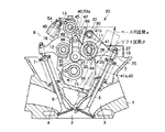
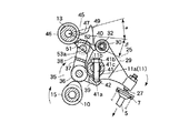
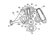
図1は、内燃機関、例えば複数気筒が直列に並ぶレシプロ式ガソリンエンジンのシリンダヘッド1の断面図を示している。このシリンダヘッド1の下面には、気筒の配列にならって燃焼室2が長手方向に沿って形成されている。これら燃焼室2毎に、例えば2個づつ(一対)、吸気ポート3および排気ポート4(片側しか図示せず)が設けてある。さらにシリンダヘッド1の上部には、吸気ポート3を開閉する吸気バルブ5(往復バルブで構成される)、排気ポート4を開閉する排気バルブ6(往復バルブで構成される)がそれそれ組付けられている。なお、複数の吸気バルブ5、複数の排気バルブ6には、いずれもバルブスプリング7で閉方向に付勢される常閉式が用いてある。またシリンダヘッド1の上部には、複数の吸気バルブ5、複数の排気バルブ6を駆動させる動弁系、例えばSOHC式の動弁系8が搭載されている。
FIG. 1 shows a cross-sectional view of a
この動弁系8について説明すると、10は、燃焼室2の頭上にシリンダヘッド1の長手方向に回転自在に配設されたカムシャフト、11は、このカムシャフト10を挟む上部片側(シリンダヘッド幅方向片側)で上記カムシャフト10とほぼ平行に配置されて支持された回動可能な吸気側のロッカシャフト、12は、その反対側に上記カムシャフト10とほぼ平行に配設(固定)された排気側のロッカシャフト、13は、ロッカシャフト10の近傍、例えばロッカシャフト11とロッカシャフト12間の上側の地点に、上記カムシャフト10とほぼ平行に配設(固定)された支持シャフト(本願の支持軸に相当)を示す。カムシャフト10は、エンジンのクランク出力により、図1中の矢印方向に沿って回転駆動される部品である。このカムシャフト10には、燃焼室2毎、吸気用カム15(1つ)と排気用カム16(2つ)が形成されている。具体的には、吸気用カム15は燃焼室2の頭上中央となるシャフト部分に形成され、排気用カム16はその吸気用カム15を挟む両側の部分にそれぞれ形成してある(図2に図示)。
The valve system 8 will be described.
このうち排気側のロッカシャフト12には、排気用カム16毎(排気バルブ6毎)に、排気バルブ6駆動用のロッカアーム18(図1;片側しか図示せず)がそれぞれ回動自在に設けられている。また吸気側のロッカシャフト11には、吸気用カム15毎に、複数(一対)の吸気バルブ5を一緒に駆動するロッカアーム機構19が設けられていて、カムシャフト10の回転により、所定の燃焼サイクル(例えば吸気行程、圧縮行程、爆発行程、排気行程の4サイクル)にしたがい、吸気バルブ5、排気バルブ6を開閉させるようにしてある。
Among them, the
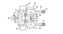
この吸気側のロッカアーム機構19に、可変動弁装置20が採用されている。図2にはこの可変動弁装置20を構成するロッカアーム機構19の平面図が示され、図3には同ロカアーム機構19を分解した斜視図が示されている。
A
同可変動弁装置20を説明すると、同装置20を構成するロッカアーム機構19には、図1〜図3に示されるようにロッカシャフト11に揺動自在に支持されるロッカアーム25(第1アームに相当)と、吸気用カム15で駆動されるセンタロッカアーム35(第2アームに相当)と、支持シャフト13に揺動自在に支持されるスイングカム45(第3アームに相当)とを組み合わせた構造が用いられている。
The
このうちロッカアーム25には、例えば図3に示されるような複数(一対)の吸気バルブ5へ変位を伝える部分を二股形状にした構造が採用されている。例えばロッカアーム25は、中央に筒状のロッカシャフト支持用ボス26を有し、そのボス26を挟んだ一端側に、吸気バルブ5の駆動をなす駆動部分、例えばアジャストスクリュ部27をもつ一対のロッカアーム片29を並行に配置し、これらロッカアーム片29の他端部間に、当接子となるローラ部材30を回転自在に挟み込んだ構造が用いられている。なお、32はローラ部材30を回転自在に枢支するための短シャフトを示す。そして、組み上げられたロッカアーム25の各ロッカシャフト支持用ボス26がロッカシャフト11に揺動自在に嵌挿され、ローラ部材30をシリンダヘッド1の中央側に向け、残るアジャストスクリュ部27をそれぞれシリンダヘッド1の上部から突き出ている吸気バルブ5の上部端(バルブステム端)に配置させてある。
Of these, the
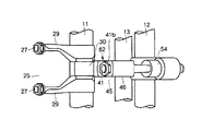
またセンタロッカアーム35には、図1および図3に示されるように吸気用カム15のカム面と転接する転接子、例えばカムフォロア36と、同カムフォロア36を回転自在に支持する枠形のホルダ部37とをもつ、ほぼL形部材が用いられている。具体的には、センタロッカアーム35は、カムフォロア36を中心として、ホルダ部37から上方、具体的にはロッカシャフト11と支持シャフト13間へ向かって柱状に延びる中継用アーム部38と、ホルダ部37の側部から、一対のロッカアーム片29間から露出するロッカシャフト部分11a(図5〜図8に図示)の下側へ延びる平板状の支点用アーム部39とを有して、L形に形成してある。そして、中継用アーム部38の先端(上端面)には、スイングカム45へ変位を伝える中継面として、例えばロッカシャフト11側が低く、支持シャフト13側が高くなるよう傾斜させた傾斜面40(本願の駆動面に相当)が形成してある。残る支点用アーム部39の先端部は、ロッカシャフト部分11aに支持されている。この支持には、図1、図3、図4〜図8に示されるようにロッカシャフト部分11aに、支点用アーム部39と組み合うピン部材41(本願の中継部材に相当)を直径方向(径方向)に組付けた構造が用いられている。すなわち、ピン部材41には、下端部に球面状部41aが形成され、外周面におねじ部41cが形成された部品が用いられている。このピン部材41は、ロッカシャフト部分11aの上側に形成された据付座11b(例えば切欠部よりなる)から下側(径方向)へ貫通するよう、支点用アーム部39の先端部に向って進退可能に螺挿、さらには据付座11b上から突き出た端部をロック用ナット41bで締め付けることによって、ロッカシャフト部分11aに固定してある。なお、図示はしないがロッカシャフト部分41cのピン部材41が貫通する通孔はねじ孔で形成されている。そして、ロッカシャフト部分11bの下端部から突き出たピン端部が支点用アーム部39に支持させてある。具体的には、支点用アーム部39の先端部上面には、ロッカシャフト部分11aから突き出た球面状部41aと回動(可動)可能に嵌まり合う半球面状の受け部42が形成されていて、同支持によりカムフォロア36が吸気用カム15で駆動されると、センタロッカアーム35が、ロッカシャフト11側を支点、すなわち球面状部41aと受け部42とが嵌まり合うピボット部を支点に、上下方向へ揺動するようにしてある。
Further, as shown in FIGS. 1 and 3, the
またロッカシャフト11の端部には、制御アクチュエータとして、例えば制御用モータ43(図3のみ図示)が接続されていて、制御用モータ43の作動により、ロッカシャフト11を所望に回動変位、例えば図5および図6に示されるピン部材41が略垂直方向に配置された姿勢から、図7および図8に示されるカムシャフト回転方向に傾いた姿勢までの範囲で回動変位できるようにしている。つまり、制御モータ43、ピボット支持構造で構成される支点移動機構44により、センタロッカアーム35のロッカシャフト11側の支点を、同シャフト11の軸方向と交差する方向に移動(変位)できるようにしている。そして、この移動がもたらすセンタロッカアーム35の位置ずれを利用して、図5〜図8に示されるようにカムフォロア36の吸気用カム15に対する転接位置(当接位置)が可変、すなわち吸気用カム15の回転方向前後へ変位できるようにしている。
Further, for example, a control motor 43 (shown only in FIG. 3) is connected to the end of the
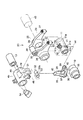
一方、スイングカム45は、図1〜図3に示されるように支持シャフト13に回動自在に嵌挿される筒状のボス部46と、同ボス部46からローラ部材30(ロッカアーム25)へ向って延びるアーム部47と、同アーム部47の下部に形成した変位受け部48とを有して形成されている。このうちアーム部47の先端には、ロッカアーム25へ変位を伝える伝達面部として、例えば上下方向に延びるカム面49が形成されている。このカム面49がロッカアーム25のローラ部材30の外周面に転接させてある。また変位受け部48には、例えば図3に示されるようにアーム部47の下部のうち、カムシャフト10の直上となる下面部分に凹陥部51を形成し、同凹陥部51内に、シャフト10,11と同じ向きで、短シャフト52(本願の軸部材に相当)を回転自在に収めた構造が用いられている。つまり、短シャフト52は、スイングカム45の揺動方向に回動自在に支持させてある。また凹陥部51の開放部から露出する短シャフト52の下部外周部には、凹部53が形成されている。そして、同凹部53内に中継用アーム部38(センタロッカアーム35)の先端部が摺動自在に差し込まれている。この凹部53の底面には、平面状の受け面53a(本願の被駆動面に相当)が形成されていて、同受け面53aが傾斜面40と面接触して、該傾斜面40をスライド可能に受け止めている。
On the other hand, as shown in FIGS. 1 to 3, the
これにより、スイングカム45は、センタロッカアーム35の揺動変位を受けると、支持シャフト13が支点とし、凹部53をセンタロッカアーム35からの荷重が作用する作用点とし、カム面49がロッカアーム25を駆動させる力点として、周期的に揺動する構造にしてあると同時に、カムフォロア36が吸気用カム15の所定位置から進角方向や遅角方向へ変位(センタロッカアーム35が吸気用カム15の移動方向前後へ変位)すると、該変位に伴うスイングアーム45の姿勢の変化から、吸気用カム15の位相が進角方向(あるいは遅角方向)へずれるようにしてある。
As a result, when the
またカム面49には、例えば支持シャフト13の中心からの距離が変化する曲面(本願の変換部)が用いられている。これには、例えば図1中に示されるようにカム面49の上部側をベース円区間α、すなわち図1中に示されるように支持シャフト13の軸心を中心とした円弧面で形成された区間とし、下部側をリフト区間β、すなわち上記円弧に連続した反対向きの円弧面及びさらに反対向きの円弧面、例えば吸気用カム15のリフト域のカム形状と同じような円弧面で形成された区間とした曲面が用いられている。このカム面49により、カムフォロア36が吸気用カム14の所定位置から進角方向へ変位(センタロッカアーム35の支点位置が変位)すると、ローラ部材30が接するカム面49の領域が変化、詳しくはローラ部材30が行き交うベース円区間αとリフト区間βの比率が変化するようにしてある。この進角方向の位相変化を伴いながら行われる区間α,βの比率の変化により、吸気バルブ5の開閉タイミングが開弁時期よりも閉弁時期を大きく可変されたり、同時に吸気バルブ5のバルブリフト量が連続的に可変されたりしている。
The
またピン部材41の上端部には、回動操作を受ける受け部として例えばプラス形の溝部60が形成されている。そして、このピン部材41の溝部60と、先に述べたピン部材41の螺挿構造と、先に述べたピン部材41をロックするナット41bとの組み合わせから、吸気バルブ5の開弁時期を気筒毎に調整可能とした機構、すなわち調整機構62を構成している。さらに述べれば、同調整機構62は、エンジンの非作動時に、図4に示されるようにピン部材41を作業の邪魔とならない向きに位置決めた姿勢から、例えばナット工具63でナット41bのアンロック・ロック操作を行い、例えばドライバー案内治具64およびプラス形のドライバー65を併用してピン部材41の回転操作を行うことにより、ピン部材41の先端の突出量が可変されるようにしてある。つまり、突出量の可変がもたらす、センタロッカアーム35の位置(姿勢)、スイングカム45の位置(姿勢)の変更により、吸気バルブ5へ伝わる開弁時期が調整される構造にしている。
Further, for example, a plus-shaped
なお、図1中、54はロッカアーム18、センタロッカアーム35およびスイングアーム45の相互間を密接する方向に付勢するためのプッシャ、55は燃焼室2内の混合気を点火する点火プラグを示す。
In FIG. 1,
つぎに、このように構成された可変動弁装置20の作用を説明する。
Next, the operation of the variable
まず、吸気バルブ5の開閉に伴うロッカアーム機構19の動きについて説明すれば、今、カムシャフト10が回転(矢印方向)しているとする。
First, the movement of the
このとき、センタロッカアーム35のカムフォロア36は、ロッカアーム片29間に配置されている吸気用カム15を受けていて、同カム15のカムプロフィールにならい駆動される。すると、センタロッカアーム35は、ロッカシャフト11側のピボット部を支点として上下方向へ揺動される。この揺動変位が、センタロッカアーム35の直上にあるスイングカム45へ伝わる。
At this time, the
ここで、スイングカム45は、一端部が支持シャフト13で揺動自在に支持され、他端部がロッカアーム25のローラ部材30に転接されている。この状態から、下部に有る回転自在な短シャフト52に形成した受け面53aで、中継用アーム部38先端の傾斜面40を受けている。これにより、スイングカム45は、傾斜面40をすべりながら、該傾斜面40で押し上げられたり下降したりするといった挙動を繰り返す。このスイングカム45の揺動により、カム面49は上下方向へ駆動される。
Here, one end portion of the
このとき、カム面49には、ローラ部材30が転接しているから、カム面49でローラ部材30を周期的に押圧する。この押圧を受けてロッカアーム25は、ロッカシャフト11を支点に駆動(揺動)され、複数(一対)の吸気バルブ5を一度に開閉させる。
At this time, since the
こうした運転中、制御モータ43の作動により、ロッカシャフト11を回動させ、例えば最大バルブリフト量が確保される地点に、センタロッカアーム35の支点位置を移動させる。すると、支点位置の変位から、センタロッカアーム35のカムフォロア36は、吸気用カム15上を変位して、スイングカム45のカム面49を垂直に近い角度(ベース円区間αにあるとき)となる姿勢に位置決められる。
During such operation, the operation of the control motor 43 causes the
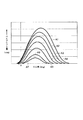
これにより、カム面49は、ローラ部材30が行き交う領域(比率)が、最大のバルブリフト量をもたらす領域、すなわち図5に示される最も短いベース円区間αと図6に示される最も長いリフト区間βに設定される。すると、吸気バルブ5は、狭いベース円区間αと最も長いリフト区間βとがなすカム面部分で駆動されるロッカアーム25にしたがい、図9中のA1の線図に示されるような最大バルブリフト量、さらには所望とする開閉タイミングで開閉される。
As a result, the
この状態から、吸気用カム15の位相を可変するときは、図7および図8に示されるように制御モータ43の作動により、ロッカシャフト11を最大バルブリフト量が確保される位置(図5および図6中のピン部材41位置)から、時計方向へ回動させる。これにより、センタロッカアーム35のピボット部(支点位置)は、カムシャフト10側へずれる。
When the phase of the
ここで、センタロッカアーム35は、スイングアーム45へ変位を伝える部分が、中継用アーム部38の傾斜面40と同傾斜面40と面接触する短シャフト52の受け面53aとにより形成され、吸気用カム15を受ける部分が吸気用カム15と転接するカムフォロア36で形成されているから、上記変位(ずれ)を受けると、センタロッカアーム35の全体は、カムフォロア36の転接位置が吸気用カム15の進角方向へ進むように変位(ずれ)する。この転接位置の変化により、可変しようとするカム位相の開弁時期が、ピボット部(支点位置)の可変量に応じて早まる。
Here, the
また傾斜面40も、支点の移動を受けて、当初の位置から受け面53a上を進角方向へ変位(スライド)する。これにより、スイングカム45は、図7および図8に示されるようにカム面49が下側へ傾く姿勢に変わる。この傾きが大きくなるにしたがい、ローラ部材30が行き交うカム面49の領域は、ベース円区間αが次第に長く、リフト区間βが次第に短くなる比率の領域に変わる。そして、この可変したカム面49のカムプロフィールがローラ部材30へ伝達され、ロッカアーム25を、開弁時期を早めながら揺動駆動する。これにより、吸気バルブ5の開閉タイミングは、センタロッカアーム35の支点位置の移動にしたがい、図9中に示されるように最大バルブリフト量A1から、ピン部材41が傾くことで得られる最小バルブリフト量A7まで、最大バルブリフト時とほぼ同じ開弁時期から開弁するタイミングを保ちながら、連続的に可変制御される。なお、図7および図8は、この可変制御のうち、最小バルブリフト量A7にしたときの状態を示している。
The
これにより、ロッカアーム25、センタロッカアーム35およびスイングカム45を組み合わせた単一のロッカアーム機構19だけで、閉弁時期を大きく変化させるカム位相の可変ができる。特に支点移動機構44は、回動可能なロッカシャフト11にピン部材41を設け、同ピン部材41の端部をセンタロッカアーム35の支点部に支持する構造なので、部品点数、さらには占有面積が抑えられた簡素なコンパクトな機構ですむ。このため、可変動弁装置20のコンパクト化が図れる利点も併せもつ。
As a result, the cam phase that greatly changes the valve closing timing can be varied only by the single
しかも、スイングカム45は、支持シャフト13からカム面49までの距離を変化させて、ロッカアーム25へ伝わるカム位相をバルブリフト量と共に連続的に可変させる構造が用いてあるので、開弁時期よりも閉弁時期を大きく変化させて連続的に吸気バルブ5の開閉タイミングおよびバルブのリフト量の可変を同時に行うことができる。こうした閉弁時期を可変するタイミングでのバルブリフト量、開閉タイミングの連続的な可変は、ロスを抑えながら吸入空気を気筒内へ吸入させることができ、特にポンピングロスの低減に優れた効果を発揮する。
In addition, the
そのうえ、調整機構62により、シリンダヘッド1に可変動弁装置20を組付けたままの状態から、気筒毎の開弁時期のばらつきが容易に調整できる。すなわち、開弁時期のばらつきを調整するときは、エンジンの非作動時において、まず、作業の邪魔とならないよう、ロッカシャフト11を回動操作して、例えば図4に示されるようにピン部材41を、頭部(ナット41bがある端部)がロッカアーム片29,29間に臨む姿勢、例えば45°程度傾いた姿勢に位置決める。ついで、ナット工具63の先端を、ロッカアーム片29,29間から、ピン部材41の頭部にあるナット41bに嵌め、同ナット工具63の回動操作により、ナット41bを弛める。この後、ナット工具63に代えて、同様にドライバー治具64の先端を、ロッカアーム片29,29間から、ナット41bから突き出ているピン部材41の端部に嵌め、図4中の二点鎖線に示されるようにドライバー治具64の後端からピン部材41の端部までの間にドライバー65を挿入するための案内路66を形成する。ついで、この案内路66を通じて、ドライバー65の先端側を挿入し、先端のプラス形(図示しない)をピン部材41端に形成されているプラス形の溝部60へ差込み、ドライバー65を回動操作して、ピン部材41の突出量を加減すれば、センタロッカアーム35の位置(姿勢)、スイングカム45の位置(姿勢)が変更されて、スイングカム45のロッカアーム25を駆動する駆動位置が調整される。これにより、各アームの揺動範囲が調整され、気筒毎に独立して吸気バルブ5の開弁時期の調整が行える。
In addition, the
それ故、駆動位置を調整するといった比較的簡単な構成の調整機構62により、可変動動弁装置20の組付け後、容易に、気筒毎における可変動弁装置20の各部品の組付誤差や複数気筒間の開閉期間のばらつきの調整ができる。この調整により、気筒間の燃焼が均一にでき、燃費の向上や気筒間の燃焼状態の差がもたらす振動等の発生を減少させることができる。しかも、調整機構62は、ロッカアーム25に対する駆動位置を調整可能としたから、調整は簡単な構成ですむ。特に調整機構52には、スイングカム45のロッカアーム25に対する駆動位置を直接的に調整する構成が用いてあるので、比較的簡単に調整ができる。そのうえ、調整機構52には、ロッカシャフト11にピン部材41を組付けてバルブ開弁時期の可変を行う構造のうち、ピン部材41の突出量を加減する構造が用いてあるから、バルブタイミングを可変調整するときのセンタロッカアーム45、スイングカム45の姿勢変化をそのまま用いて、バルブ開弁時期の調整ができ、容易に気筒間におけるばらつきを正すことができる。特に調整機構62は、カムシャフト10の回転に連動しない部位に設けてあるので、弁作動時の慣性重量は特性され、良好なエンジン性能をもたらす。本実施形態のように調整機構62をロッカシャフト11に設けるようにすると、可変動弁装置20のスペースを有効に活用して、調整機構62が設置でき、可変動弁装置20の大型化が抑制されるという利点もたらす。
Therefore, after the assembly of the variable
なお、本実施形態において、位相可変装置を併用しても、位相可変量は小さくてすむため、可変する応答性が生じず、十分な燃費の改善が図れる利点がある。 In this embodiment, even if the phase variable device is used in combination, the phase variable amount can be small, so that there is no variable response and there is an advantage that sufficient fuel consumption can be improved.
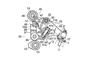
[第2の実施形態]
図10および図11は、本発明の第2の実施形態の要部を示す。
[Second Embodiment]
10 and 11 show the main part of the second embodiment of the present invention.
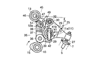
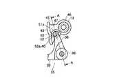
本実施形態は、第1の実施形態のように調整機構62を非可動部(カムシャフトの回転に連動しない部位)に設けたのではなく、調整機構62を、可動部、具体的にはスイングカム45(第3アームに相当)に設けたものである。
In the present embodiment, the
具体的には、調整機構62として、センタロッカアーム35には、支点用アーム39の先端部をロッカアーム11の外周部下部に係止させて、該係止部39aを支点に上下方向にセンタロッカアーム全体が上下方向に揺動できるようにした構造を用い、またスイングカム45のうち、スイングカム45の揺動支点とカム面49の間のアーム部分47には、ロック用のナット41bが付いたピン部材41を、上側から貫通するよう進退可能に螺挿して、スイングカム45の下部から突き出た先端の球面状部41を、センタロッカアーム35の中継用アーム部38の端部に形成した半球面状の受け部42に嵌まり合わせた構造が用いられている。これにより、先に説明した第1の実施形態と同様、エンジンの非作動時に、例えばナット工具やプラス方のドライバー(いずれも図示しない)を併用して、ピン部材41の先端の突出量を加減することにより、バルブ開弁時期の調整が行えるようにしている。
Specifically, as the
このようにしても第1の実施形態と同様の効果を奏する。特にこのようにスイングカム45に調整機構62を設けると、エンジンの上方から容易に調整機構62へアクセスできるので、他の部品との干渉等が生じることなく、容易に組付誤差や気筒間のばらつきを調整することができる利点を有する。
Even if it does in this way, there exists an effect similar to 1st Embodiment. In particular, when the
[第3の実施形態]
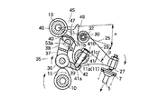
図12および図13は、本発明の第3の実施形態の要部を示す。
[Third Embodiment]
12 and 13 show the main part of the third embodiment of the present invention.
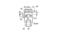
本実施形態は、調整機構62として、第1、2の実施形態のようなピン部材を用いた構造ではなく、センタロッカアーム35(第2アーム)とスイングカム45(第3アーム)との間に介在する短シャフト52(軸部材)を用い、同短シャフト52を形状(高さ)が異なる多数種(1種類だけ図示)、用意しておき、調整時に適切な短シャフト52に適宜組み替えるようにしたものである。
This embodiment is not a structure using a pin member as in the first and second embodiments as the
具体的には、調整機構62は、例えば図12および図13に示されるようにスイングカム45の下部に形成されている挿通孔51aに挿脱可能に収められる短シャフト52を、受け面53a(被駆動面)の高さ寸法Hが異なる凹部53をもつ複数の種類、用意しておき(1種類だけ図示)、短シャフトを組み換えることで、センタロッカアーム35の傾斜面40(駆動面)との接触具合から、センタロッカアーム35に対するスイングカム45の相対位置を変化させて、スイングカム45のロッカアーム(図示しない)に対する駆動位置を調整する構造が用いてある。
Specifically, the adjusting
このようにしても第1の実施形態と同様の効果を奏する。特にこのように調整機構62は、ピン部材52を取り換える構造なので、新たな部品が必要にならないため、部品点数の低減および重量の低減を図ることができる。
Even if it does in this way, there exists an effect similar to 1st Embodiment. In particular, since the
但し、第2および第3の実施形態において、第1の実施形態と同じ部分には同一符号を附してその説明を省略した。 However, in the second and third embodiments, the same parts as those in the first embodiment are denoted by the same reference numerals, and the description thereof is omitted.
なお、本発明は上述した実施形態に限定されるものではなく、本発明の主旨を逸脱しない範囲内で種々変更して実施しても構わない。例えば上述した実施形態では、調整機構として、ピン部材をロッカシャフトやスイングカムに貫通させて組付ける構造を用いたり、短シャフトを組み換える構造を用いたが、これに限らず、他の構造でもよい。また調整機構も、螺挿構造、ナット構造、ドライバー操作構造を組み合わせた構造を用いているが、これに限らず、他の構造でもよい。また一実施形態では、本発明を吸気バルブのロッカアーム機構に適用した例を挙げたが、これに限らず、排気バルブのロッカアーム機構に適用してもよい。また上述の実施形態では、SOHC式動弁系(1本のカムシャフトで吸気バルブと排気バルブを駆動する構造)のエンジンに本発明を適用したが、これに限らず、DOHC式動弁系(カムシャフトが吸気側と排気側とに専用にある構造)のエンジンに本発明を適用してもよい。 In addition, this invention is not limited to embodiment mentioned above, You may implement in various changes within the range which does not deviate from the main point of this invention. For example, in the above-described embodiment, as the adjustment mechanism, a structure in which the pin member is inserted through the rocker shaft or the swing cam is used or a structure in which the short shaft is recombined is used. Good. Further, the adjustment mechanism uses a structure in which a screw insertion structure, a nut structure, and a driver operation structure are combined. However, the structure is not limited to this, and another structure may be used. In one embodiment, the present invention is applied to the rocker arm mechanism of the intake valve. However, the present invention is not limited to this, and may be applied to the rocker arm mechanism of the exhaust valve. In the above-described embodiment, the present invention is applied to an engine of an SOHC valve system (a structure in which an intake valve and an exhaust valve are driven by a single camshaft). However, the present invention is not limited to this, and a DOHC valve system ( The present invention may be applied to an engine having a structure in which camshafts are dedicated to the intake side and the exhaust side.
5…吸気バルブ、6…排気バルブ、10…カムシャフト、11…吸気側のロッカシャフト、13…支持シャフト(支持軸)、19…ロッカアーム機構、20…可変動弁装置、25…ロッカアーム(第1アーム)、30…ローラ部材、35…センタロッカアーム(第2アーム)、40…傾斜面(駆動面)、41…ピン部材(中継部材)、41a…球面状部、41b…ナット、41c…おねじ部、42…半球面状の受け部、45…スイングカム(第3アーム)、49…カム面(伝達面部)、52…短シャフト(軸部材)、53a…受け面(非駆動面)、62…調整機構、α,β…ベース円区間,リフト区間。
DESCRIPTION OF
Claims (10)
前記内燃機関の非作動時に、前記動力伝達部材の前記吸気又は排気バルブ側を駆動する駆動位置を調整可能な調整機構を設けたことを特徴とする内燃機関の可変動弁装置。 An internal combustion engine having a plurality of cylinders is driven by a camshaft rotatably provided, has a power transmission member that opens and closes an intake valve or an exhaust valve, and drives the intake valve or exhaust valve side of the power transmission member In a variable valve operating apparatus for an internal combustion engine that changes a lift amount of the intake valve or the exhaust valve by changing a drive range,
A variable valve operating apparatus for an internal combustion engine, comprising an adjustment mechanism capable of adjusting a drive position for driving the intake or exhaust valve side of the power transmission member when the internal combustion engine is not operated.
前記カムシャフトに形成されたカムと当接して該カムにより駆動され、前記ロッカシャフト側を支点として揺動する第2アームと、
前記ロッカシャフトの近傍に配置された支持軸に揺動自在に設けられ、前記第2アームの変位を受け、前記第2アームの支点移動がもたらす該第2アームの姿勢変化にしたがい、前記カムの位相を可変させて前記第1アームを駆動する第3アームとを有し、
前記調整機構は、前記第3アームの前記第1アームに対する駆動位置を前記内燃機関の非作動時に調整可能とする
ことを特徴とする請求項3又は請求項4のいずれかに記載の内燃機関の可変動弁装置。 The power transmission member is
A second arm that abuts on a cam formed on the camshaft and is driven by the cam and swings around the rocker shaft side;
The cam is provided on a support shaft disposed in the vicinity of the rocker shaft so as to be swingable. The displacement of the second arm causes a change in the posture of the second arm caused by movement of the fulcrum of the second arm. A third arm that drives the first arm with a variable phase;
5. The internal combustion engine according to claim 3, wherein the adjustment mechanism is capable of adjusting a drive position of the third arm relative to the first arm when the internal combustion engine is not in operation. Variable valve gear.
前記ロッカシャフトの回転変位に伴う前記中継部材の姿勢変化により、前記第2ロッカアームの支点が変位することを特徴とする請求項5に記載の内燃機関の可変動弁装置。 The rocker shaft has a relay member supported so that the tip portion protrudes, and the tip portion is movably supported by the rocker shaft side support portion of the second arm,
6. The variable valve operating apparatus for an internal combustion engine according to claim 5, wherein a fulcrum of the second rocker arm is displaced by a change in posture of the relay member accompanying a rotational displacement of the rocker shaft.
ロッカシャフトに揺動自在に支持され前記吸気又は排気バルブを駆動可能な第1アームを備え、
前記動力伝達部材は、
前記カムシャフトに形成されたカムと当接して該カムにより駆動され、前記ロッカシャフト側を支点として揺動する第2アームと、
前記ロッカシャフトの近傍に配置された支持軸に揺動自在に設けられ、前記第2アームの変位を受け、前記第2アームの支点移動がもたらす該第2アームの姿勢変化にしたがい、前記カムの位相を可変させて前記第1アームを駆動する第3アームとを有し、
前記内燃機関の非作動時に、前記第3アームの前記第1アームに対する駆動位置を調整可能な調整機構を前記第3アームに設けた
ことを特徴とする内燃機関の可変動弁装置。 An internal combustion engine having a plurality of cylinders is driven by a camshaft rotatably provided, has a power transmission member that opens and closes an intake valve or an exhaust valve, and drives the intake valve or exhaust valve side of the power transmission member In a variable valve operating apparatus for an internal combustion engine that changes a lift amount of the intake valve or the exhaust valve by changing a drive range,
A first arm supported on a rocker shaft in a swingable manner and capable of driving the intake or exhaust valve;
The power transmission member is
A second arm that abuts on a cam formed on the camshaft and is driven by the cam and swings around the rocker shaft side;
The cam is provided on a support shaft disposed in the vicinity of the rocker shaft so as to be capable of swinging, and is subjected to displacement of the second arm. A third arm that drives the first arm with a variable phase;
The variable valve operating apparatus for an internal combustion engine, wherein an adjustment mechanism capable of adjusting a driving position of the third arm relative to the first arm when the internal combustion engine is not operated is provided in the third arm.
ロッカシャフトに揺動自在に支持され前記吸気又は排気バルブを駆動可能な第1アームを備え、
前記動力伝達部材は、
前記カムシャフトに形成されたカムと当接して該カムにより駆動され、前記ロッカシャフト側を支点として揺動する第2アームと、
前記ロッカシャフトの近傍に配置された支持軸に揺動自在に設けられ、前記第2アームの変位を受け、前記第2アームの支点移動がもたらす該第2アームの姿勢変化にしたがい、前記カムの位相を可変させて前記第1アームを駆動する第3アームとを有し、
前記第2アームは、前記第3アームを駆動する駆動面を有し、
前記第3アームは、該第3アームの揺動方向に回動自在に支持され、かつ外周部に前記駆動面と面接触する被駆動面が形成された軸部材を有し、
前記軸部材を前記被駆動面が異なる別個の軸部材に取り換えることにより、前記第2アームに対する前記第3アームの相対位置を変化させ、第3アームの前記第1アームに対する駆動位置を調整可能とした
ことを特徴とする内燃機関の可変動弁装置。 An internal combustion engine having a plurality of cylinders is driven by a camshaft rotatably provided, has a power transmission member that opens and closes an intake valve or an exhaust valve, and drives the intake valve or exhaust valve side of the power transmission member In a variable valve operating apparatus for an internal combustion engine that changes a lift amount of the intake valve or the exhaust valve by changing a drive range,
A first arm supported on a rocker shaft in a swingable manner and capable of driving the intake or exhaust valve;
The power transmission member is
A second arm that abuts on a cam formed on the camshaft and is driven by the cam and swings around the rocker shaft side;
The cam is provided on a support shaft disposed in the vicinity of the rocker shaft so as to be swingable. The displacement of the second arm causes a change in the posture of the second arm caused by movement of the fulcrum of the second arm. A third arm that drives the first arm with a variable phase;
The second arm has a drive surface for driving the third arm;
The third arm includes a shaft member that is rotatably supported in the swinging direction of the third arm and has a driven surface that is in surface contact with the driving surface on the outer periphery.
By replacing the shaft member with a separate shaft member having a different driven surface, the relative position of the third arm with respect to the second arm can be changed, and the driving position of the third arm with respect to the first arm can be adjusted. A variable valve operating apparatus for an internal combustion engine, characterized by comprising:
前記内燃機関の非作動時に、各気筒の前記吸気バルブ又は前記排気バルブの開閉期間を調整可能な調整機構を備えた
ことを特徴とする内燃機関の可変動弁装置。 An internal combustion engine having a plurality of cylinders is driven by a camshaft rotatably provided, has a power transmission member that opens and closes an intake valve or an exhaust valve, and drives the intake valve or exhaust valve side of the power transmission member In a variable valve operating apparatus for an internal combustion engine that changes a lift amount of the intake valve or the exhaust valve by changing a drive range,
A variable valve operating apparatus for an internal combustion engine comprising an adjustment mechanism capable of adjusting an opening / closing period of the intake valve or the exhaust valve of each cylinder when the internal combustion engine is not operated.
Priority Applications (6)
| Application Number | Priority Date | Filing Date | Title |
|---|---|---|---|
| JP2004117812A JP4221327B2 (en) | 2004-04-13 | 2004-04-13 | Variable valve operating device for internal combustion engine |
| CN2008100839054A CN101413411B (en) | 2004-04-13 | 2005-04-12 | Variable valve device for internal combustion engine |
| CNB200510067271XA CN100552191C (en) | 2004-04-13 | 2005-04-12 | Variable valve device for internal combustion engine |
| KR1020050030205A KR100690468B1 (en) | 2004-04-13 | 2005-04-12 | Variable drive valve device of internal combustion engine |
| US11/103,556 US7314027B2 (en) | 2004-04-13 | 2005-04-12 | Variable valve unit for internal combustion engine |
| DE102005017064A DE102005017064B4 (en) | 2004-04-13 | 2005-04-13 | Variable valve unit for internal combustion engine |
Applications Claiming Priority (1)
| Application Number | Priority Date | Filing Date | Title |
|---|---|---|---|
| JP2004117812A JP4221327B2 (en) | 2004-04-13 | 2004-04-13 | Variable valve operating device for internal combustion engine |
Related Child Applications (4)
| Application Number | Title | Priority Date | Filing Date |
|---|---|---|---|
| JP2008270348A Division JP5148449B2 (en) | 2008-10-20 | 2008-10-20 | Variable valve operating device for internal combustion engine |
| JP2008270351A Division JP5148451B2 (en) | 2008-10-20 | 2008-10-20 | Variable valve operating device for internal combustion engine |
| JP2008270350A Division JP5042963B2 (en) | 2008-10-20 | 2008-10-20 | Variable valve operating device for internal combustion engine |
| JP2008270349A Division JP5148450B2 (en) | 2008-10-20 | 2008-10-20 | Variable valve operating device for internal combustion engine |
Publications (2)
| Publication Number | Publication Date |
|---|---|
| JP2005299536A true JP2005299536A (en) | 2005-10-27 |
| JP4221327B2 JP4221327B2 (en) | 2009-02-12 |
Family
ID=35220116
Family Applications (1)
| Application Number | Title | Priority Date | Filing Date |
|---|---|---|---|
| JP2004117812A Expired - Fee Related JP4221327B2 (en) | 2004-04-13 | 2004-04-13 | Variable valve operating device for internal combustion engine |
Country Status (5)
| Country | Link |
|---|---|
| US (1) | US7314027B2 (en) |
| JP (1) | JP4221327B2 (en) |
| KR (1) | KR100690468B1 (en) |
| CN (2) | CN101413411B (en) |
| DE (1) | DE102005017064B4 (en) |
Cited By (20)
| Publication number | Priority date | Publication date | Assignee | Title |
|---|---|---|---|---|
| WO2007013458A1 (en) * | 2005-07-25 | 2007-02-01 | Mitsubishi Jidosha Kogyo Kabushiki Kaisha | Variable valve gear of internal combustion engine |
| WO2007013460A1 (en) * | 2005-07-25 | 2007-02-01 | Mitsubishi Jidosha Kogyo Kabushiki Kaisha | Variable valve gear of internal combustion engine |
| JP2008025413A (en) * | 2006-07-19 | 2008-02-07 | Honda Motor Co Ltd | Valve operating device for internal combustion engine |
| EP1918536A1 (en) * | 2006-10-31 | 2008-05-07 | Mitsubishi Jidosha Kogyo Kabushiki Kaisha | Valve unit of internal combustion engine |
| JP2008196314A (en) * | 2007-02-08 | 2008-08-28 | Toyota Motor Corp | Variable valve gear |
| JP2008202478A (en) * | 2007-02-19 | 2008-09-04 | Mitsubishi Motors Corp | Valve operating device for internal combustion engine |
| JP2008202580A (en) * | 2007-02-22 | 2008-09-04 | Mitsubishi Motors Corp | Variable valve mechanism for internal combustion engine |
| EP1972763A1 (en) | 2007-02-22 | 2008-09-24 | Mitsubishi Jidosha Kogyo Kabushiki Kaisha | Variable valve mechanism for internal combustion engine |
| DE102008014080A1 (en) | 2007-07-04 | 2009-01-08 | Mitsubishi Jidosha Kogyo Kabushiki Kaisha | Variable valve train for an internal combustion engine |
| DE102008016857A1 (en) | 2007-06-29 | 2009-01-15 | Mitsubishi Jidosha Kogyo K.K. | Variable valve control system for internal combustion engines |
| US7644690B2 (en) | 2006-10-31 | 2010-01-12 | Mitsubishi Jidosha Kogyo Kabushiki Kaisha | Arrangement structure of electrically-driven actuator |
| JP2010053708A (en) * | 2008-08-26 | 2010-03-11 | Mitsubishi Motors Corp | Variable valve gear of internal combustion engine |
| JP2010096046A (en) * | 2008-10-15 | 2010-04-30 | Mitsubishi Motors Corp | Dual head rocker arm assembling method |
| DE102009052767A1 (en) | 2008-11-12 | 2010-07-08 | Mitsubishi Jidosha Kogyo K.K. | Variable valve mechanism for an internal combustion engine |
| JP2010159639A (en) * | 2009-01-06 | 2010-07-22 | Mitsubishi Motors Corp | Cylinder variation adjusting tool |
| DE102009052766A1 (en) | 2008-11-12 | 2010-08-05 | Mitsubishi Jidosha Kogyo Kabushiki Kaisha | Variable valve mechanism for an internal combustion engine |
| JP2011069376A (en) * | 2011-01-14 | 2011-04-07 | Mitsubishi Motors Corp | Variable valve gear for internal combustion engine |
| JP2011069377A (en) * | 2011-01-14 | 2011-04-07 | Mitsubishi Motors Corp | Variable valve gear for internal combustion engine |
| EP2357341A1 (en) | 2010-02-15 | 2011-08-17 | Mitsubishi Jidosha Kogyo Kabushiki Kaisha | Internal combustion engine control unit |
| CN117552852A (en) * | 2024-01-12 | 2024-02-13 | 潍柴动力股份有限公司 | Engine and its valvetrain |
Families Citing this family (12)
| Publication number | Priority date | Publication date | Assignee | Title |
|---|---|---|---|---|
| WO2005090758A1 (en) * | 2004-03-23 | 2005-09-29 | Mitsubishi Fuso Truck And Bus Corporation | Variable valve gear of internal combustion engine |
| DE102006002133B4 (en) * | 2006-01-17 | 2025-05-15 | Bayerische Motoren Werke Aktiengesellschaft | Valve train for variable stroke actuation of a gas exchange valve of an internal combustion engine |
| US7633755B2 (en) * | 2007-11-15 | 2009-12-15 | Fu Zhun Precision Industry (Shen Zhen) Co., Ltd. | Heat dissipation device assembly with a fan duct having guiding members for guiding a screwdriver to assemble the heat dissipation device assembly to a printed circuit board |
| EP2381074A1 (en) * | 2010-04-20 | 2011-10-26 | Kwang Yang Motor Co., Ltd. | Variable valve lift mechanism for engine and arrangement of oil control valve |
| US8622039B2 (en) * | 2010-12-22 | 2014-01-07 | James T. Dougherty | Rockerless desmodromic valve system |
| EP2668385A4 (en) * | 2011-01-27 | 2015-11-04 | Scuderi Group Inc | Split-cycle air hybrid engine with dwell cam |
| WO2012103401A2 (en) | 2011-01-27 | 2012-08-02 | Scuderi Group, Llc | Lost-motion variable valve actuation system with cam phaser |
| CN103443408A (en) | 2011-01-27 | 2013-12-11 | 史古德利集团公司 | Lost motion variable valve actuation system with valve deactivation |
| US9109468B2 (en) | 2012-01-06 | 2015-08-18 | Scuderi Group, Llc | Lost-motion variable valve actuation system |
| US9291106B2 (en) * | 2013-03-15 | 2016-03-22 | Tula Technology, Inc. | Cam phaser control |
| EP2971636A1 (en) | 2013-03-15 | 2016-01-20 | Scuderi Group, Inc. | Split-cycle engines with direct injection |
| DE102013205533A1 (en) * | 2013-03-28 | 2014-10-02 | Schaeffler Technologies Gmbh & Co. Kg | Method for mounting a valve train of an internal combustion engine |
Family Cites Families (17)
| Publication number | Priority date | Publication date | Assignee | Title |
|---|---|---|---|---|
| USRE35662E (en) * | 1990-01-18 | 1997-11-18 | Mitsubishi Jidosha Kogyo Kabushiki Kaisha | Valve operating apparatus |
| JP2566480B2 (en) * | 1990-06-15 | 1996-12-25 | 本田技研工業株式会社 | Fuel injection internal combustion engine |
| DE4326331A1 (en) * | 1992-07-15 | 1995-02-09 | Bayerische Motoren Werke Ag | Valve gear of an internal combustion engine |
| US5329895A (en) | 1992-09-30 | 1994-07-19 | Mazda Motor Corporation | System for controlling valve shift timing of an engine |
| JPH06173619A (en) * | 1992-12-08 | 1994-06-21 | Yamaha Motor Co Ltd | 4-cycle engine valve mechanism |
| DE4311877C2 (en) * | 1993-04-10 | 1996-05-15 | Hatz Motoren | Camshaft drive |
| SE501437C2 (en) * | 1993-06-22 | 1995-02-13 | Volvo Ab | Valve mechanism in an internal combustion engine |
| EP0638706A1 (en) * | 1993-08-05 | 1995-02-15 | Bayerische Motoren Werke Aktiengesellschaft | Valve actuating mechanism of an internal combustion engine |
| CA2214301C (en) * | 1996-09-02 | 2001-04-24 | Honda Giken Kogyo Kabushiki Kaisha (Also Trading As Honda Motor Co., Ltd .) | Valve operating system in internal combustion engine |
| JP3916819B2 (en) | 1999-11-29 | 2007-05-23 | 株式会社日立製作所 | Engine valve actuator |
| DE10136612A1 (en) * | 2001-07-17 | 2003-02-06 | Herbert Naumann | Variable lift valve controls |
| DE10221133A1 (en) * | 2002-05-13 | 2003-11-27 | Thyssen Krupp Automotive Ag | Drive and adjustment system for variable valve controls |
| US6722331B2 (en) * | 2002-06-28 | 2004-04-20 | Tecumseh Products Company | Valve clearance adjustment mechanism |
| JP4151357B2 (en) * | 2002-09-09 | 2008-09-17 | トヨタ自動車株式会社 | Variable valve mechanism for internal combustion engine |
| DE10304991A1 (en) * | 2003-02-07 | 2004-08-19 | Ina-Schaeffler Kg | Adjusting device for effecting lifting functions of lever-type cam-driven transmission links works in a varied valve mechanism for controlling a spark-ignition internal combustion engine under load |
| JP4381188B2 (en) * | 2004-03-19 | 2009-12-09 | 三菱ふそうトラック・バス株式会社 | Variable valve operating device for internal combustion engine |
| WO2005090758A1 (en) * | 2004-03-23 | 2005-09-29 | Mitsubishi Fuso Truck And Bus Corporation | Variable valve gear of internal combustion engine |
-
2004
- 2004-04-13 JP JP2004117812A patent/JP4221327B2/en not_active Expired - Fee Related
-
2005
- 2005-04-12 KR KR1020050030205A patent/KR100690468B1/en not_active Expired - Fee Related
- 2005-04-12 CN CN2008100839054A patent/CN101413411B/en not_active Expired - Fee Related
- 2005-04-12 US US11/103,556 patent/US7314027B2/en not_active Expired - Lifetime
- 2005-04-12 CN CNB200510067271XA patent/CN100552191C/en not_active Expired - Fee Related
- 2005-04-13 DE DE102005017064A patent/DE102005017064B4/en not_active Expired - Fee Related
Cited By (30)
| Publication number | Priority date | Publication date | Assignee | Title |
|---|---|---|---|---|
| WO2007013460A1 (en) * | 2005-07-25 | 2007-02-01 | Mitsubishi Jidosha Kogyo Kabushiki Kaisha | Variable valve gear of internal combustion engine |
| WO2007013458A1 (en) * | 2005-07-25 | 2007-02-01 | Mitsubishi Jidosha Kogyo Kabushiki Kaisha | Variable valve gear of internal combustion engine |
| US7757647B2 (en) | 2005-07-25 | 2010-07-20 | Mitsubishi Jidosha Kogyo Habushiki Kaisha | Variable valve apparatus of internal combustion engine |
| US7748358B2 (en) | 2005-07-25 | 2010-07-06 | Mitsubishi Jidosha Kogyo Kabushiki Kaisha | Variable valve train apparatus for internal combustion engine |
| JP2008025413A (en) * | 2006-07-19 | 2008-02-07 | Honda Motor Co Ltd | Valve operating device for internal combustion engine |
| US7644690B2 (en) | 2006-10-31 | 2010-01-12 | Mitsubishi Jidosha Kogyo Kabushiki Kaisha | Arrangement structure of electrically-driven actuator |
| EP1918536A1 (en) * | 2006-10-31 | 2008-05-07 | Mitsubishi Jidosha Kogyo Kabushiki Kaisha | Valve unit of internal combustion engine |
| US7658172B2 (en) | 2006-10-31 | 2010-02-09 | Mitsubishi Jidosha Kogyo Kabushiki Kaisha | Valve unit of internal combustion engine |
| JP2008196314A (en) * | 2007-02-08 | 2008-08-28 | Toyota Motor Corp | Variable valve gear |
| JP2008202478A (en) * | 2007-02-19 | 2008-09-04 | Mitsubishi Motors Corp | Valve operating device for internal combustion engine |
| US7836861B2 (en) | 2007-02-22 | 2010-11-23 | Mitsubishi Jidosha Kogyo Kabushiki Kaisha | Variable valve mechanism for internal combustion engine |
| EP1972763A1 (en) | 2007-02-22 | 2008-09-24 | Mitsubishi Jidosha Kogyo Kabushiki Kaisha | Variable valve mechanism for internal combustion engine |
| JP2008202580A (en) * | 2007-02-22 | 2008-09-04 | Mitsubishi Motors Corp | Variable valve mechanism for internal combustion engine |
| US7730859B2 (en) | 2007-06-29 | 2010-06-08 | Mitsubishi Jidosha Kogyo Kabushiki Kaisha | Variable valve train system for internal combustion engine |
| DE102008016857A1 (en) | 2007-06-29 | 2009-01-15 | Mitsubishi Jidosha Kogyo K.K. | Variable valve control system for internal combustion engines |
| US7770550B2 (en) | 2007-07-04 | 2010-08-10 | Mitsubishi Jidosha Kogyo Kabushiki Kaisha | Variable valve train for an internal combustion engine |
| DE102008014080A1 (en) | 2007-07-04 | 2009-01-08 | Mitsubishi Jidosha Kogyo Kabushiki Kaisha | Variable valve train for an internal combustion engine |
| DE102008014080B4 (en) * | 2007-07-04 | 2013-12-24 | Mitsubishi Jidosha Kogyo Kabushiki Kaisha | Variable valve train for an internal combustion engine |
| JP2010053708A (en) * | 2008-08-26 | 2010-03-11 | Mitsubishi Motors Corp | Variable valve gear of internal combustion engine |
| JP2010096046A (en) * | 2008-10-15 | 2010-04-30 | Mitsubishi Motors Corp | Dual head rocker arm assembling method |
| DE102009052766A1 (en) | 2008-11-12 | 2010-08-05 | Mitsubishi Jidosha Kogyo Kabushiki Kaisha | Variable valve mechanism for an internal combustion engine |
| DE102009052767A1 (en) | 2008-11-12 | 2010-07-08 | Mitsubishi Jidosha Kogyo K.K. | Variable valve mechanism for an internal combustion engine |
| DE102009052767B4 (en) | 2008-11-12 | 2021-12-23 | Mitsubishi Jidosha Kogyo K.K. | Variable valve mechanism for an internal combustion engine |
| DE102009052766B4 (en) | 2008-11-12 | 2022-02-10 | Mitsubishi Jidosha Kogyo Kabushiki Kaisha | Variable valve mechanism for an internal combustion engine |
| JP2010159639A (en) * | 2009-01-06 | 2010-07-22 | Mitsubishi Motors Corp | Cylinder variation adjusting tool |
| EP2357341A1 (en) | 2010-02-15 | 2011-08-17 | Mitsubishi Jidosha Kogyo Kabushiki Kaisha | Internal combustion engine control unit |
| JP2011069376A (en) * | 2011-01-14 | 2011-04-07 | Mitsubishi Motors Corp | Variable valve gear for internal combustion engine |
| JP2011069377A (en) * | 2011-01-14 | 2011-04-07 | Mitsubishi Motors Corp | Variable valve gear for internal combustion engine |
| CN117552852A (en) * | 2024-01-12 | 2024-02-13 | 潍柴动力股份有限公司 | Engine and its valvetrain |
| CN117552852B (en) * | 2024-01-12 | 2024-04-16 | 潍柴动力股份有限公司 | Engine and valve mechanism thereof |
Also Published As
| Publication number | Publication date |
|---|---|
| JP4221327B2 (en) | 2009-02-12 |
| KR100690468B1 (en) | 2007-03-09 |
| CN100552191C (en) | 2009-10-21 |
| KR20060045606A (en) | 2006-05-17 |
| CN101413411A (en) | 2009-04-22 |
| DE102005017064A1 (en) | 2005-11-24 |
| DE102005017064B4 (en) | 2012-02-09 |
| US20050274340A1 (en) | 2005-12-15 |
| CN101413411B (en) | 2011-01-05 |
| US7314027B2 (en) | 2008-01-01 |
| CN1683759A (en) | 2005-10-19 |
Similar Documents
| Publication | Publication Date | Title |
|---|---|---|
| JP4221327B2 (en) | Variable valve operating device for internal combustion engine | |
| CN100460631C (en) | Variable valve gear for internal combustion engines | |
| JP4293167B2 (en) | Variable valve operating device for internal combustion engine | |
| JP4697011B2 (en) | Variable valve mechanism | |
| JP4293168B2 (en) | Variable valve operating device for internal combustion engine | |
| JP5148451B2 (en) | Variable valve operating device for internal combustion engine | |
| JP5148449B2 (en) | Variable valve operating device for internal combustion engine | |
| JP5148450B2 (en) | Variable valve operating device for internal combustion engine | |
| JP5042963B2 (en) | Variable valve operating device for internal combustion engine | |
| JP4195463B2 (en) | Variable valve operating device for internal combustion engine | |
| US7168404B2 (en) | Variable valve apparatus of internal combustion engine | |
| JP4118248B2 (en) | Variable valve operating device for internal combustion engine | |
| JP4507997B2 (en) | Variable valve operating device for internal combustion engine | |
| JP4180011B2 (en) | Variable valve operating device for internal combustion engine | |
| JP4180013B2 (en) | Variable valve operating device for internal combustion engine | |
| JP4180014B2 (en) | Variable valve operating device for internal combustion engine | |
| JP4566071B2 (en) | Internal combustion engine | |
| JP4180012B2 (en) | Variable valve operating device for internal combustion engine | |
| JP4225294B2 (en) | Variable valve operating device for internal combustion engine | |
| JP4552707B2 (en) | Variable valve operating device for internal combustion engine | |
| JP2006220121A (en) | Cylinder head of internal combustion engine | |
| JP2007107432A (en) | Valve operating device for internal combustion engine | |
| JP2007107431A (en) | Valve operating device for internal combustion engine |
Legal Events
| Date | Code | Title | Description |
|---|---|---|---|
| A621 | Written request for application examination |
Free format text: JAPANESE INTERMEDIATE CODE: A621 Effective date: 20060630 |
|
| A131 | Notification of reasons for refusal |
Free format text: JAPANESE INTERMEDIATE CODE: A131 Effective date: 20080527 |
|
| A977 | Report on retrieval |
Free format text: JAPANESE INTERMEDIATE CODE: A971007 Effective date: 20080529 |
|
| A521 | Request for written amendment filed |
Free format text: JAPANESE INTERMEDIATE CODE: A523 Effective date: 20080728 |
|
| A131 | Notification of reasons for refusal |
Free format text: JAPANESE INTERMEDIATE CODE: A131 Effective date: 20080819 |
|
| A521 | Request for written amendment filed |
Free format text: JAPANESE INTERMEDIATE CODE: A523 Effective date: 20081020 |
|
| TRDD | Decision of grant or rejection written | ||
| A01 | Written decision to grant a patent or to grant a registration (utility model) |
Free format text: JAPANESE INTERMEDIATE CODE: A01 Effective date: 20081111 |
|
| A01 | Written decision to grant a patent or to grant a registration (utility model) |
Free format text: JAPANESE INTERMEDIATE CODE: A01 |
|
| A61 | First payment of annual fees (during grant procedure) |
Free format text: JAPANESE INTERMEDIATE CODE: A61 Effective date: 20081117 |
|
| FPAY | Renewal fee payment (event date is renewal date of database) |
Free format text: PAYMENT UNTIL: 20111121 Year of fee payment: 3 |
|
| R150 | Certificate of patent or registration of utility model |
Free format text: JAPANESE INTERMEDIATE CODE: R150 |
|
| FPAY | Renewal fee payment (event date is renewal date of database) |
Free format text: PAYMENT UNTIL: 20121121 Year of fee payment: 4 |
|
| FPAY | Renewal fee payment (event date is renewal date of database) |
Free format text: PAYMENT UNTIL: 20121121 Year of fee payment: 4 |
|
| FPAY | Renewal fee payment (event date is renewal date of database) |
Free format text: PAYMENT UNTIL: 20131121 Year of fee payment: 5 |
|
| R250 | Receipt of annual fees |
Free format text: JAPANESE INTERMEDIATE CODE: R250 |
|
| R250 | Receipt of annual fees |
Free format text: JAPANESE INTERMEDIATE CODE: R250 |
|
| R250 | Receipt of annual fees |
Free format text: JAPANESE INTERMEDIATE CODE: R250 |
|
| LAPS | Cancellation because of no payment of annual fees |