JP2005299523A - Wind power generator - Google Patents
Wind power generator Download PDFInfo
- Publication number
- JP2005299523A JP2005299523A JP2004117523A JP2004117523A JP2005299523A JP 2005299523 A JP2005299523 A JP 2005299523A JP 2004117523 A JP2004117523 A JP 2004117523A JP 2004117523 A JP2004117523 A JP 2004117523A JP 2005299523 A JP2005299523 A JP 2005299523A
- Authority
- JP
- Japan
- Prior art keywords
- fixed
- rotating shaft
- wind
- side mounting
- mounting bars
- Prior art date
- Legal status (The legal status is an assumption and is not a legal conclusion. Google has not performed a legal analysis and makes no representation as to the accuracy of the status listed.)
- Granted
Links
Images
Classifications
-
- Y—GENERAL TAGGING OF NEW TECHNOLOGICAL DEVELOPMENTS; GENERAL TAGGING OF CROSS-SECTIONAL TECHNOLOGIES SPANNING OVER SEVERAL SECTIONS OF THE IPC; TECHNICAL SUBJECTS COVERED BY FORMER USPC CROSS-REFERENCE ART COLLECTIONS [XRACs] AND DIGESTS
- Y02—TECHNOLOGIES OR APPLICATIONS FOR MITIGATION OR ADAPTATION AGAINST CLIMATE CHANGE
- Y02E—REDUCTION OF GREENHOUSE GAS [GHG] EMISSIONS, RELATED TO ENERGY GENERATION, TRANSMISSION OR DISTRIBUTION
- Y02E10/00—Energy generation through renewable energy sources
- Y02E10/70—Wind energy
- Y02E10/72—Wind turbines with rotation axis in wind direction
Landscapes
- Control Of Eletrric Generators (AREA)
- Wind Motors (AREA)
Abstract
Description
この発明は、風の力により翼車を回転させて、その回転のエネルギを電気エネルギに変換する風力発電装置に関する。 The present invention relates to a wind turbine generator that rotates an impeller by wind force and converts the energy of the rotation into electric energy.
この種の風力発電装置としては、従来から様々な種類のものが考案され、各種型式のものが提案され製作されている。それらのうち、作動時に風の方向に沿う水平回転軸を持つ水平軸型の風力発電装置は、一般に、2〜4枚程度の羽根を有するプロペラ(翼車)を水平回転軸に固着し、水平回転軸を回転自在に軸受によって支持するとともに、水平回転軸の回転のエネルギが発電機によって電気エネルギに変換されるようにし、軸受および発電機を保持した保持部材(ケーシング)を鉛直軸周りに回転自在に支柱上に支持し、プロペラが固着された水平回転軸が常に風向に沿うようにする機構を備えて構成されている(例えば、特許文献1参照。)。
従来の風力発電装置のうちの多くのものは、風の力を如何に効率良く電気エネルギに変換するか、といった観点から開発されている。また、従来の風力発電装置では、金属やプラスチック材料などで形成された羽根の角度を調節することにより、風力(風速)の変化に対してプロペラの回転数をほぼ一定にする、といった工夫もなされている。さらに、強風による羽根の破損を防止するような安全機構についても、種々検討されている。しかしながら、従来のそれらの機構は、複雑化したものが多い。また、従来の風力発電装置では、羽根などが破損すると、その修理に手間と時間がかかり、修理費用も高くなる、といった問題点がある。 Many of the conventional wind power generators have been developed from the viewpoint of how efficiently wind power is converted into electric energy. In addition, in the conventional wind power generator, the propeller rotation speed is made substantially constant with respect to changes in wind force (wind speed) by adjusting the angle of the blades made of metal or plastic material. ing. Furthermore, various safety mechanisms for preventing the blades from being damaged by a strong wind have been studied. However, these conventional mechanisms are often complicated. Moreover, in the conventional wind power generator, when a blade | wing etc. are damaged, the trouble and time are required for the repair, and repair cost becomes high.
この発明は、以上のような事情に鑑みてなされたものであり、極めて簡易な構成でありながら、風力が変化してもほぼ一定の電気エネルギが効率的に得られ、強風による羽根の破損も防止することができ、例え羽根などが破損したとしても、その修理が簡単で費用も余りかからない風力発電装置を提供することを目的とする。 The present invention has been made in view of the circumstances as described above. Although it has an extremely simple configuration, even when the wind force changes, a substantially constant electric energy can be efficiently obtained, and the blades are damaged by the strong wind. An object of the present invention is to provide a wind turbine generator that can be prevented and, even if a blade or the like is damaged, can be easily repaired and does not cost much.
請求項1に係る発明は、保持部材に水平姿勢でかつ回転自在に支持された回転軸と、この回転軸に取着され風の力を受けて回転軸と一体的に回転する翼車と、回転のエネルギを電気エネルギに変換する発電機と、前記回転軸の回転動力を前記発電機の回転子に伝達する伝動機構と、前記回転軸を風向に沿わせるように水平面内で回動させる向き調整機構と、を備えた風力発電装置において、前記翼車を、前記回転軸に固着された固定部材と、この固定部材に放射状にかつ円周方向に等配されて固着された複数本の風上側取付棒と、前記回転軸の、前記固定部材の後方側に、固定部材と間隔を設け回転軸に対して摺動自在に取着された可動部材と、この可動部材に放射状にかつ円周方向に等配され、前記各風上側取付棒にそれぞれ対応するようにかつ風上側取付棒と角度位置をずらして固着された、風上側取付棒と同数本の風下側取付棒と、前記各風上側取付棒と前記各風下側取付棒との間にそれぞれ張設された複数枚の羽根と、これらの羽根が受ける風力が大きいほど前記風上側取付棒から前記風下側取付棒が離間するようにかつ風上側取付棒とそれに対応する風下側取付棒との角度位置のずれが小さくなるように、前記回転軸に対し前記可動部材を移動および回動させる回転数自動調整機構と、を備えて構成したことを特徴とする。 The invention according to claim 1 is a rotating shaft that is horizontally supported and rotatably supported by the holding member, an impeller that is attached to the rotating shaft and receives the force of wind and rotates integrally with the rotating shaft; A generator that converts rotational energy into electrical energy, a transmission mechanism that transmits the rotational power of the rotating shaft to the rotor of the generator, and a direction in which the rotating shaft rotates in a horizontal plane so as to follow the wind direction. A wind power generator comprising: an adjustment mechanism; and a plurality of winds fixed to the fixed member that is fixed to the rotating shaft and radially arranged in the circumferential direction on the fixed member. An upper mounting rod, a movable member spaced apart from the fixed member on the rear side of the fixed member and attached to be slidable with respect to the rotary shaft, and a radial and circumferential surface on the movable member So as to correspond to each of the windward side mounting rods. In addition, the same number of leeward side mounting rods as that of the windward side mounting rods, which are fixed to the windward side mounting rods at different angular positions, are stretched between the respective windward side mounting rods and the respective leeward side mounting rods. In addition, the larger the wind force received by the blades, the larger the wind force received by these blades, the more the leeward side mounting rods are separated from the windward side mounting rods and the angular positions of the windward side mounting rods and the corresponding leeward side mounting rods. An automatic rotation number adjusting mechanism for moving and rotating the movable member with respect to the rotation shaft so as to reduce the deviation is provided.
請求項2に係る発明は、請求項1記載の風力発電装置において、前記回転数自動調整機構が、前記回転軸の外周面に、回転軸の軸線方向に沿いながら捩れるように穿設された案内溝と、前記可動部材に固着され先端部が前記案内溝に対し摺動自在に嵌合した係合ピンと、前記可動部材を前記固定部材に対して接近させるように付勢する弾発手段と、により構成されたことを特徴とする。 According to a second aspect of the present invention, in the wind turbine generator according to the first aspect, the automatic rotation speed adjusting mechanism is formed on the outer peripheral surface of the rotating shaft so as to be twisted along the axial direction of the rotating shaft. A guide groove, an engagement pin fixed to the movable member and having a tip slidably fitted to the guide groove, and a resilient means for biasing the movable member to approach the fixed member It is characterized by comprising.
請求項1に係る発明の風力発電装置においては、風力が大きくなると、翼車の風上側取付棒と風下側取付棒との間に張設された羽根の受ける力が大きくなり、その力によって可動部材が、回転軸に固着された固定部材から遠ざかるように回転軸に対し移動しつつ回転軸の軸心線周りに回動する。これにより、風上側取付棒から風下側取付棒が離間するとともに風上側取付棒とそれに対応する風下側取付棒との角度位置のずれが小さくなって、風の進行方向から見える羽根の見掛け上の面積が小さくなる。この結果、風から羽根の受ける力が小さくなる。このため、風力が大きくなっても、翼車の回転数、したがって回転軸の回転数の増大が抑えられる。そして、風力の大きさに応じて可動部材の移動距離および回動角度が変化し、風の進行方向から見える羽根の見掛け上の面積が変化するので、風力が変化しても、回転軸の回転数の変動が抑えられる。また、回転軸の回転数の増大が抑えられるので、強風による羽根の破損が防止される。
したがって、請求項1に係る発明の風力発電装置を使用すると、風力が変化してもほぼ一定の電気エネルギを効率的に得ることができ、強風による羽根の破損も防止することができる。そして、この風力発電装置は、極めて簡易な構成を有しており、例え羽根などが破損したとしても、その修理が簡単で費用も余りかからない。
In the wind power generator according to the first aspect of the present invention, when the wind power increases, the force received by the blades stretched between the windward side mounting rod and the leeward side mounting rod of the impeller increases, and is movable by the force. The member rotates around the axis of the rotating shaft while moving relative to the rotating shaft so as to move away from the fixed member fixed to the rotating shaft. As a result, the leeward side mounting rod is separated from the windward side mounting rod, and the deviation of the angular position between the windward side mounting rod and the corresponding leeward side mounting rod is reduced. The area becomes smaller. As a result, the force received by the blade from the wind is reduced. For this reason, even if wind force becomes large, the increase in the rotation speed of an impeller and hence the rotation speed of a rotating shaft can be suppressed. The moving distance and rotation angle of the movable member change according to the magnitude of the wind force, and the apparent area of the blades seen from the direction of wind movement changes. Number fluctuation is suppressed. Moreover, since the increase in the rotation speed of the rotating shaft is suppressed, the blades are prevented from being damaged by the strong wind.
Therefore, when the wind power generator of the invention according to claim 1 is used, substantially constant electric energy can be efficiently obtained even if the wind force changes, and damage to the blades due to strong wind can be prevented. And this wind power generator has a very simple configuration, and even if the blades are damaged, the repair is simple and does not cost much.
請求項2に係る発明の風力発電装置では、風力が大きくなって羽根の受ける力が大きくなると、可動部材は、弾発手段の弾発力に抗し、可動部材に固着された係合ピンの先端部が回転軸の案内溝に対し摺動しつつ案内溝により案内されて、回転軸に固着された固定部材から遠ざかるように回転軸に対し移動しつつ、回転軸の軸心線周りに回動する。これにより、風上側取付棒から風下側取付棒が離間するとともに風上側取付棒とそれに対応する風下側取付棒との角度位置のずれが小さくなって、風の進行方向から見える羽根の見掛け上の面積が小さくなる。一方、風力が小さくなって羽根の受ける力が小さくなると、可動部材は、弾発手段の付勢力が羽根の受ける力に打ち克ち、係合ピンの先端部が回転軸の案内溝に対し摺動しつつ案内溝により案内されて、固定部材に近づくように回転軸に対し移動しつつ、回転軸の軸心線周りに、前記とは逆の方向に回動する。これにより、風上側取付棒から風下側取付棒が接近するとともに風上側取付棒とそれに対応する風下側取付棒との角度位置のずれが大きくなって、風の進行方向から見える羽根の見掛け上の面積が大きくなる。
したがって、請求項2に係る発明の風力発電装置では、極めて簡易な構成により、風力の変化に伴う回転軸の回転数の変動を抑えることができ、また、回転軸の回転数の増大を抑えて、強風による羽根の破損を防止することができる。
In the wind turbine generator according to the second aspect of the invention, when the wind force increases and the force received by the blades increases, the movable member resists the resilient force of the resilient means, and the engagement pin fixed to the movable member The tip is guided by the guide groove while sliding with respect to the guide groove of the rotary shaft, and moves around the axis of the rotary shaft while moving with respect to the rotary shaft so as to move away from the fixed member fixed to the rotary shaft. Move. As a result, the leeward side mounting rod is separated from the windward side mounting rod, and the deviation of the angular position between the windward side mounting rod and the corresponding leeward side mounting rod is reduced. The area becomes smaller. On the other hand, when the wind force is reduced and the force received by the blade is reduced, the movable member overcomes the force received by the blade by the urging force of the elastic means, and the tip of the engagement pin slides against the guide groove of the rotating shaft. It is guided by the guide groove while moving and moves relative to the rotating shaft so as to approach the fixed member, and rotates in the opposite direction around the axis of the rotating shaft. As a result, the leeward side mounting rod approaches from the windward side mounting rod, and the deviation of the angular position between the windward side mounting rod and the corresponding leeward side mounting rod becomes large, so that the appearance of the blades seen from the wind traveling direction is apparent. Increases area.
Therefore, in the wind turbine generator according to the second aspect of the present invention, fluctuations in the rotational speed of the rotating shaft accompanying changes in wind power can be suppressed with an extremely simple configuration, and an increase in the rotational speed of the rotating shaft can be suppressed. The blades can be prevented from being damaged by the strong wind.
以下、この発明の最良の実施形態について図面を参照しながら説明する。
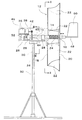
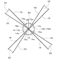
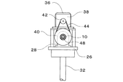
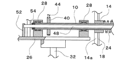
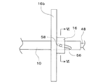
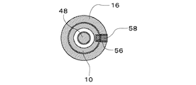
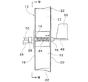
図1ないし図6は、この発明の実施形態の1例を示し、図1は、風力発電装置の側面図であり、図2は、図1のII−II矢視断面図であり、図3は、図1のIII−III矢視断面図である。また、図4は、図1に示した装置の一部を拡大した部分断面図であり、図5は、図1に示した装置の一部を拡大した側面図であり、図6は、図5のVI−VI矢視断面図である。
DESCRIPTION OF THE PREFERRED EMBODIMENTS Hereinafter, the best embodiment of the present invention will be described with reference to the drawings.
1 to 6 show an example of an embodiment of the present invention, FIG. 1 is a side view of a wind power generator, FIG. 2 is a cross-sectional view taken along the line II-II in FIG. FIG. 3 is a cross-sectional view taken along arrow III-III in FIG. 1. 4 is an enlarged partial cross-sectional view of a part of the apparatus shown in FIG. 1, FIG. 5 is an enlarged side view of the part of the apparatus shown in FIG. 1, and FIG. FIG. 5 is a cross-sectional view taken along line VI-VI in FIG.
この風力発電装置は、作動時に風の方向に沿う水平回転軸10を備えた水平軸型の装置であって、水平回転軸10に翼車12が取着されており、翼車12は、風を受けて水平回転軸10と一体的に回転するようになっている。この翼車12は、水平回転軸10に固着された固定カラー14、および、水平回転軸10の、固定カラー14の後方側に、固定カラー14と間隔を設けて取着された可動カラー16を備え、可動カラー16は、水平回転軸10に対して摺動自在に保持されている。固定カラー14および可動カラー16はそれぞれ、図2に示すように、取付け用のリブ14a、16aおよびホイール14b、16bを具備している。そして、固定カラー14には、複数本、図示例では4本の風上側取付棒18が放射状にかつ円周方向に等配されて固着されている。また、可動カラー16にも、風上側取付棒18と同数本、図示例では4本の風下側取付棒20が放射状にかつ円周方向に等配されて固着されている。各風上側取付棒18と各風下側取付棒20とは、それぞれ互いに対応するようにかつ角度位置をずらして配置されている。そして、対応する風上側取付棒18と風下側取付棒20との間に羽根22が張設されている。羽根22は、例えば防水加工が施されたポリエステル、ポリビニルアセタール等の布帛で製作される。また、固定カラー14と可動カラー16との間には、水平回転軸10の外周側に巻回された引っ張りコイルばね24が介装され、引っ張りコイルばね24の両端部が固定カラー14および可動カラー16にそれぞれ固着されている。したがって、可動カラー16および風下側取付棒20は、引っ張りコイルばね24の弾発力により固定カラー14および風上側取付棒18に対して接近するように付勢される。
This wind power generator is a horizontal shaft type device provided with a horizontal rotating
水平回転軸10は、保持台板26の上面に固設された一対の軸受28、28によって回転自在に支持され、保持台板26により軸受28を介して片持ち式に水平姿勢で保持されている。保持台板26は、下面側には回転支軸30が一体的に垂設されており、回転支軸30は、支柱32の軸心部に形設された支持孔34に回動自在に嵌挿されている。そして、保持台板26は、支柱32の上端部に水平姿勢で保持され、鉛直軸周りに自由回転するようになっている。
The horizontal
保持台板26上には、回転のエネルギを電気エネルギに変換する発電機36、および、回転動力を伝達するためのギヤボックス38がそれぞれ固設されており、発電機36の回転子とギヤボックス38の出力軸とが連結されている。また、水平回転軸10に大径プーリ40が一体的に固着され、ギヤボックス38の入力軸に小径プーリ42が一体的に固着されていて、両プーリ40、42間にベルト44が掛け回されている。なお、図1に二点鎖線で示すように、保持台板26の上面側はカバー46で覆蓋され、保持台板26とカバー46からなるケーシング内に軸受28、発電機36、ギヤボックス38などが収納される。
On the holding
水平回転軸10は、図4に示すように中空となっており、その軸心部に固定桿48が挿通されていて、水平回転軸10の後端面から突き出た固定桿48の後端部に方向舵50が固着されている。また、水平回転軸10の前端面から突き出た固定桿48の前端部は、保持台板26の上面に固設されたブラケット52に固着されており、固定桿48は保持台板26に対して固定されている。したがって、固定桿48に固着された方向舵50の作用により、水平回転軸10を風向に沿わせるように、保持台板26と固定桿48とは一体となって水平面内で回動するようになっている。また、水平回転軸10の前・後両端部(図4には前端部だけを示している)には、軸受54がそれぞれ取着されており、その軸受54を介して水平回転軸10と固定桿48とが連接している。したがって、固定桿48に対して水平回転軸10の回転動作が許容されるとともに、水平回転軸10に固定桿48が支持されている。
The horizontal
水平回転軸10の後端付近の外周面には、図5に示すように、水平回転軸10の軸線方向に沿いながら軸心線周りに捩れるように案内溝56が穿設されている。また、図6に示すように、可動カラー16に係合ピン58が固着されており、その係合ピン58の先端部が水平回転軸10の案内溝56に対し摺動自在に嵌合している。このような構造により、可動カラー16は、その係合ピン58の先端部が水平回転軸10の案内溝56に対し摺動しつつ案内溝56により案内されて、水平回転軸10に固着された固定カラー14から遠ざかるように水平回転軸10に対し移動しつつ水平回転軸10の軸心線周りに回動し、また、固定カラー14に近づくように水平回転軸10に対し移動しつつ水平回転軸10の軸心線周りにかつ前記とは逆の方向に回動するようになっている。
As shown in FIG. 5, a
次に、上記したような構成を備えた風力発電装置における動作について説明する。
この風力発電装置の設置場所において風が吹くと、方向舵50の作用により、保持台板26が支柱32に対して水平面内で回動し、水平回転軸10の軸線方向を風の流れに沿わせ翼車12の前面側が風上に向いた姿勢となる。そして、風力が小さいときは、図1に示すように、翼車12の風上側取付棒18と風下側取付棒20との間の距離が最小となり、図2に示すように、風上側から翼車12を見たときの羽根22の見掛け上の面積が最大となる。このため、翼車12の羽根22は、風から最大限の力を受けることとなる。このとき、引っ張りコイルばね24には特に負荷はかからない。そして、風の力によって翼車12が水平回転軸10と共に回転し、その回転動力が大径プーリ40、ベルト44、小径プーリ42およびギヤボックス38を経て発電機36の回転子に伝達され、発電機36により回転のエネルギが電気エネルギに変換されて電力が発生する。得られた電力は、例えば、バッテリに一時的に蓄えられ、インバータを介して60Hzまたは50Hzの周波数および100Vの電圧に変換されて一般家庭で使用されたり、インバータを介し回生インバータを通じて電力会社へ供給されたりする。
Next, the operation in the wind turbine generator having the above-described configuration will be described.
When wind blows at the place where the wind power generator is installed, the
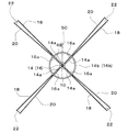
一方、風力が大きくなると、翼車12の羽根22の受ける力が大きくなり、風下側取付棒20が一体的に固着された可動カラー16は、引っ張りコイルばね24の弾発力(引っ張り力)に抗し、係合ピン58の先端部が水平回転軸10の案内溝56に対し摺動しつつ案内溝56により案内されて、固定カラー14から遠ざかるように移動しつつ、水平回転軸10の軸心線周りに回動する。これにより、図7に示すように、翼車12の風上側取付棒18と風下側取付棒20との間の距離が大きくなり、図8(図7のVIII−VIII矢視断面図)に示すように、風上側取付棒18と風下側取付棒20との角度位置のずれが小さくなって、風上側から翼車12を見たときの羽根22の見掛け上の面積が小さくなる。このため、翼車12の羽根22が風から受ける力が低減することとなる。そして、翼車12の羽根22が受ける風の力と引っ張りコイルばね24の引っ張り力とが均衡した状態となる位置に可動カラー16が保持される。このように、風力が大きいときには、翼車12の羽根22が風から受ける力を低減させるように動作するため、風力が大きくなっても、翼車12の回転数、したがって水平回転軸10の回転数の増大が抑えられる。そして、風力の大きさに応じて可動カラー16の移動距離および回動角度が変化し、風の進行方向から見える翼車12の羽根22の見掛け上の面積が変化するので、風力が変化しても、水平回転軸10の回転数の変動が抑えられる。また、水平回転軸10の回転数の増大が抑えられるので、強風によって羽根22が破損される、といったことが防止される。
On the other hand, when the wind force increases, the force received by the
そして、風力が次第に小さくなって翼車12の羽根22の受ける力が次第に小さくなると、可動カラー16は、引っ張りコイルばね24の付勢力により、係合ピン58の先端部が水平回転軸10の案内溝56に対し摺動しつつ案内溝56により案内されて、固定カラー14に近づくように移動しつつ、水平回転軸10の軸心線周りに、前記とは逆の方向に回動する。これにより、図1に示すように、翼車12の風上側取付棒18と風下側取付棒20との間の距離が小さくなり、図2に示すように、風上側取付棒18と風下側取付棒20との角度位置のずれが大きくなって、風上側から翼車12を見たときの羽根22の見掛け上の面積が大きくなる。このため、翼車12の羽根22は、風の力を効率良く受けることとなり、翼車12は一定以上の回転数で回転する。
When the wind force is gradually reduced and the force received by the
なお、上記した実施形態では、翼車12の羽根22が受ける風の力と引っ張りコイルばね24の引っ張り力とを均衡させることにより、風上側から翼車12を見たときの羽根22の見掛け上の面積が風力の大きさに応じて自動的に調整されるようにし、風力が変化しても水平回転軸10および翼車12の回転数がほぼ一定となるような構成としたが、風上側から翼車12を見たときの羽根22の見掛け上の面積を自動的に調整する機構としては、上記実施形態のものに限定されず、例えば、翼車12の羽根22が受ける風の力と水平回転軸10の回転による遠心力とを均衡させることを利用したものであってもよい。また、水平回転軸10の回転動力を発電機36に伝達する伝動機構や方向舵の機構、発電機36、軸受28などを収納するケーシングの構造、ケーシングの鉛直軸周りの自由回転機構なども、上記した実施形態のものに限定されない。
In the above-described embodiment, by balancing the wind force received by the
10 水平回転軸
12 翼車
14 固定カラー
16 可動カラー
18 風上側取付棒
20 風下側取付棒
22 羽根
24 引っ張りコイルばね
26 保持台板
28 軸受
30 回転支軸
32 支柱
34 支持孔
36 発電機
38 ギヤボックス
40、42 プーリ
44 ベルト
48 固定桿
50 方向舵
52 ブラケット
56 案内溝
58 係合ピン
DESCRIPTION OF
Claims (2)
この回転軸に取着され風の力を受けて回転軸と一体的に回転する翼車と、
回転のエネルギを電気エネルギに変換する発電機と、
前記回転軸の回転動力を前記発電機の回転子に伝達する伝動機構と、
前記回転軸を風向に沿わせるように水平面内で回動させる向き調整機構と、
を備えた風力発電装置において、
前記翼車を、
前記回転軸に固着された固定部材と、
この固定部材に放射状にかつ円周方向に等配されて固着された複数本の風上側取付棒と、
前記回転軸の、前記固定部材の後方側に、固定部材と間隔を設け回転軸に対して摺動自在に取着された可動部材と、
この可動部材に放射状にかつ円周方向に等配され、前記各風上側取付棒にそれぞれ対応するようにかつ風上側取付棒と角度位置をずらして固着された、風上側取付棒と同数本の風下側取付棒と、
前記各風上側取付棒と前記各風下側取付棒との間にそれぞれ張設された複数枚の羽根と、
これらの羽根が受ける風力が大きいほど前記風上側取付棒から前記風下側取付棒が離間するようにかつ風上側取付棒とそれに対応する風下側取付棒との角度位置のずれが小さくなるように、前記回転軸に対し前記可動部材を移動および回動させる回転数自動調整機構と、
を備えて構成したことを特徴とする風力発電装置。 A rotating shaft that is horizontally supported by the holding member and is rotatably supported;
An impeller attached to the rotating shaft and receiving the force of wind to rotate integrally with the rotating shaft;
A generator that converts rotational energy into electrical energy;
A transmission mechanism for transmitting the rotational power of the rotary shaft to the rotor of the generator;
A direction adjusting mechanism for rotating the rotating shaft in a horizontal plane so as to follow the wind direction;
In the wind turbine generator with
The impeller,
A fixing member fixed to the rotating shaft;
A plurality of windward side mounting rods that are fixed radially and circumferentially and fixed to the fixing member; and
A movable member attached to a rear side of the fixed member at a distance from the fixed member and slidably attached to the rotary shaft;
The same number of upwinding mounting rods that are radially arranged on the movable member in the circumferential direction and fixed to the upwinding mounting rods so as to correspond to the upwinding mounting rods at different angular positions. A leeward mounting rod,
A plurality of blades respectively stretched between the leeward side mounting rods and the leeward side mounting rods;
As the wind force received by these blades is larger, the leeward side mounting rod is separated from the windward side mounting rod and the angular position deviation between the windward side mounting rod and the corresponding leeward side mounting rod is reduced. A rotation number automatic adjustment mechanism for moving and rotating the movable member with respect to the rotation shaft;
A wind power generator characterized by comprising:
前記回転軸の外周面に、回転軸の軸線方向に沿いながら捩れるように穿設された案内溝と、
前記可動部材に固着され先端部が前記案内溝に対し摺動自在に嵌合した係合ピンと、
前記可動部材を前記固定部材に対して接近させるように付勢する弾発手段と、
により構成された請求項1記載の風力発電装置。 The rotation speed automatic adjustment mechanism is
A guide groove formed on the outer peripheral surface of the rotating shaft so as to be twisted along the axial direction of the rotating shaft;
An engagement pin fixed to the movable member and having a tip portion slidably fitted into the guide groove;
A resilient means for biasing the movable member to approach the fixed member;
The wind power generator of Claim 1 comprised by these.
Priority Applications (1)
| Application Number | Priority Date | Filing Date | Title |
|---|---|---|---|
| JP2004117523A JP4509633B2 (en) | 2004-04-13 | 2004-04-13 | Wind power generator |
Applications Claiming Priority (1)
| Application Number | Priority Date | Filing Date | Title |
|---|---|---|---|
| JP2004117523A JP4509633B2 (en) | 2004-04-13 | 2004-04-13 | Wind power generator |
Publications (2)
| Publication Number | Publication Date |
|---|---|
| JP2005299523A true JP2005299523A (en) | 2005-10-27 |
| JP4509633B2 JP4509633B2 (en) | 2010-07-21 |
Family
ID=35331373
Family Applications (1)
| Application Number | Title | Priority Date | Filing Date |
|---|---|---|---|
| JP2004117523A Expired - Fee Related JP4509633B2 (en) | 2004-04-13 | 2004-04-13 | Wind power generator |
Country Status (1)
| Country | Link |
|---|---|
| JP (1) | JP4509633B2 (en) |
Cited By (3)
| Publication number | Priority date | Publication date | Assignee | Title |
|---|---|---|---|---|
| WO2009011506A1 (en) * | 2007-07-16 | 2009-01-22 | Young Jae Shin | Wind power station using induction apparatus |
| CN113074088A (en) * | 2021-05-20 | 2021-07-06 | 广州赛特新能源科技发展有限公司 | Small wind driven generator |
| CN116819112A (en) * | 2023-08-29 | 2023-09-29 | 贝克曼沃玛金属技术(青岛)有限公司 | Wind vane azimuth adjusting device of wind generating set |
Citations (7)
| Publication number | Priority date | Publication date | Assignee | Title |
|---|---|---|---|---|
| JPS298608B1 (en) * | 1952-06-30 | 1954-12-27 | ||
| JPS50142935U (en) * | 1974-05-14 | 1975-11-26 | ||
| JPS5697579U (en) * | 1979-12-25 | 1981-08-01 | ||
| JPS57131873A (en) * | 1981-02-06 | 1982-08-14 | Teruo Honami | Liquid energy converting mechanism |
| JPH06200863A (en) * | 1993-01-06 | 1994-07-19 | Hideki Sato | Wind pressure sensitive type windmill blade |
| JP2005009415A (en) * | 2003-06-19 | 2005-01-13 | Suiden Co Ltd | Automatic rotation adjustment device of windmill for wind power generation |
| JP2005061291A (en) * | 2003-08-11 | 2005-03-10 | Kunio Miyazaki | Windmill structure of wind power generation device |
-
2004
- 2004-04-13 JP JP2004117523A patent/JP4509633B2/en not_active Expired - Fee Related
Patent Citations (7)
| Publication number | Priority date | Publication date | Assignee | Title |
|---|---|---|---|---|
| JPS298608B1 (en) * | 1952-06-30 | 1954-12-27 | ||
| JPS50142935U (en) * | 1974-05-14 | 1975-11-26 | ||
| JPS5697579U (en) * | 1979-12-25 | 1981-08-01 | ||
| JPS57131873A (en) * | 1981-02-06 | 1982-08-14 | Teruo Honami | Liquid energy converting mechanism |
| JPH06200863A (en) * | 1993-01-06 | 1994-07-19 | Hideki Sato | Wind pressure sensitive type windmill blade |
| JP2005009415A (en) * | 2003-06-19 | 2005-01-13 | Suiden Co Ltd | Automatic rotation adjustment device of windmill for wind power generation |
| JP2005061291A (en) * | 2003-08-11 | 2005-03-10 | Kunio Miyazaki | Windmill structure of wind power generation device |
Cited By (5)
| Publication number | Priority date | Publication date | Assignee | Title |
|---|---|---|---|---|
| WO2009011506A1 (en) * | 2007-07-16 | 2009-01-22 | Young Jae Shin | Wind power station using induction apparatus |
| CN113074088A (en) * | 2021-05-20 | 2021-07-06 | 广州赛特新能源科技发展有限公司 | Small wind driven generator |
| CN113074088B (en) * | 2021-05-20 | 2022-05-24 | 广州赛特新能源科技发展有限公司 | Small wind driven generator |
| CN116819112A (en) * | 2023-08-29 | 2023-09-29 | 贝克曼沃玛金属技术(青岛)有限公司 | Wind vane azimuth adjusting device of wind generating set |
| CN116819112B (en) * | 2023-08-29 | 2023-11-14 | 贝克曼沃玛金属技术(青岛)有限公司 | Wind vane azimuth adjusting device of wind generating set |
Also Published As
| Publication number | Publication date |
|---|---|
| JP4509633B2 (en) | 2010-07-21 |
Similar Documents
| Publication | Publication Date | Title |
|---|---|---|
| KR100870634B1 (en) | Wind generator | |
| US20090015017A1 (en) | Wind powered electricity generating system | |
| JP2005517123A (en) | Wind power generator | |
| JP2004060646A (en) | Starting wind speed reducing device for wind mill | |
| JP2008106622A (en) | Impeller rotation device for wind power generation and wind power generator provided with the rotation device | |
| JP2006037753A (en) | Windmill for wind power generation | |
| US10018189B1 (en) | Wind turbine tower cable positioning device | |
| JP4509633B2 (en) | Wind power generator | |
| JP2006052669A (en) | Wind power generation device | |
| JP2015071980A (en) | Vertical shaft type windmill and vertical shaft type windmill generator | |
| WO2009082186A1 (en) | Wind power plant | |
| KR101927309B1 (en) | Vertical wind turbine | |
| JP2019089388A (en) | Power generating flying body | |
| KR102026954B1 (en) | System of wind focus type electricity from wind energy | |
| JP6315971B2 (en) | Wind power generator | |
| JP2010261344A (en) | Wind power generator | |
| JP2009281228A (en) | Wind turbine generator | |
| JP2005256605A (en) | Wind power generating device | |
| EP3864283B1 (en) | Rotor for power driving | |
| WO2011058970A1 (en) | Wind-driven electric power-generating device | |
| JP2006299868A (en) | Automatically extendable blade | |
| KR101046175B1 (en) | Generator and wind power generation system including the same | |
| JP2005226475A (en) | Wind power generator | |
| KR102776635B1 (en) | Wind power generator capable of generating electricity even at low wind speed | |
| EP2809947B1 (en) | A wind turbine with a pitch regulation and furling out of wind |
Legal Events
| Date | Code | Title | Description |
|---|---|---|---|
| A621 | Written request for application examination |
Free format text: JAPANESE INTERMEDIATE CODE: A621 Effective date: 20070406 |
|
| A977 | Report on retrieval |
Free format text: JAPANESE INTERMEDIATE CODE: A971007 Effective date: 20100122 |
|
| A131 | Notification of reasons for refusal |
Free format text: JAPANESE INTERMEDIATE CODE: A131 Effective date: 20100209 |
|
| A521 | Written amendment |
Free format text: JAPANESE INTERMEDIATE CODE: A523 Effective date: 20100226 |
|
| TRDD | Decision of grant or rejection written | ||
| A01 | Written decision to grant a patent or to grant a registration (utility model) |
Free format text: JAPANESE INTERMEDIATE CODE: A01 Effective date: 20100406 |
|
| A01 | Written decision to grant a patent or to grant a registration (utility model) |
Free format text: JAPANESE INTERMEDIATE CODE: A01 |
|
| A61 | First payment of annual fees (during grant procedure) |
Free format text: JAPANESE INTERMEDIATE CODE: A61 Effective date: 20100428 |
|
| FPAY | Renewal fee payment (event date is renewal date of database) |
Free format text: PAYMENT UNTIL: 20130514 Year of fee payment: 3 |
|
| R150 | Certificate of patent or registration of utility model |
Ref document number: 4509633 Country of ref document: JP Free format text: JAPANESE INTERMEDIATE CODE: R150 Free format text: JAPANESE INTERMEDIATE CODE: R150 |
|
| FPAY | Renewal fee payment (event date is renewal date of database) |
Free format text: PAYMENT UNTIL: 20130514 Year of fee payment: 3 |
|
| FPAY | Renewal fee payment (event date is renewal date of database) |
Free format text: PAYMENT UNTIL: 20160514 Year of fee payment: 6 |
|
| R250 | Receipt of annual fees |
Free format text: JAPANESE INTERMEDIATE CODE: R250 |
|
| R250 | Receipt of annual fees |
Free format text: JAPANESE INTERMEDIATE CODE: R250 |
|
| R250 | Receipt of annual fees |
Free format text: JAPANESE INTERMEDIATE CODE: R250 |
|
| R250 | Receipt of annual fees |
Free format text: JAPANESE INTERMEDIATE CODE: R250 |
|
| LAPS | Cancellation because of no payment of annual fees |