JP2005299513A - Internal combustion engine, control device for internal combustion engine, and control method for internal combustion engine - Google Patents
Internal combustion engine, control device for internal combustion engine, and control method for internal combustion engine Download PDFInfo
- Publication number
- JP2005299513A JP2005299513A JP2004116992A JP2004116992A JP2005299513A JP 2005299513 A JP2005299513 A JP 2005299513A JP 2004116992 A JP2004116992 A JP 2004116992A JP 2004116992 A JP2004116992 A JP 2004116992A JP 2005299513 A JP2005299513 A JP 2005299513A
- Authority
- JP
- Japan
- Prior art keywords
- internal combustion
- combustion engine
- vehicle
- acceleration
- intention
- Prior art date
- Legal status (The legal status is an assumption and is not a legal conclusion. Google has not performed a legal analysis and makes no representation as to the accuracy of the status listed.)
- Granted
Links
Images


Classifications
-
- Y—GENERAL TAGGING OF NEW TECHNOLOGICAL DEVELOPMENTS; GENERAL TAGGING OF CROSS-SECTIONAL TECHNOLOGIES SPANNING OVER SEVERAL SECTIONS OF THE IPC; TECHNICAL SUBJECTS COVERED BY FORMER USPC CROSS-REFERENCE ART COLLECTIONS [XRACs] AND DIGESTS
- Y02—TECHNOLOGIES OR APPLICATIONS FOR MITIGATION OR ADAPTATION AGAINST CLIMATE CHANGE
- Y02T—CLIMATE CHANGE MITIGATION TECHNOLOGIES RELATED TO TRANSPORTATION
- Y02T10/00—Road transport of goods or passengers
- Y02T10/10—Internal combustion engine [ICE] based vehicles
- Y02T10/12—Improving ICE efficiencies
Landscapes
- Control Of Vehicle Engines Or Engines For Specific Uses (AREA)
- Supercharger (AREA)
- Output Control And Ontrol Of Special Type Engine (AREA)
Abstract
Description
本発明は、過給機を備える内燃機関に関するものであり、さらに詳しくは、燃料消費の悪化を抑制しつつ、加速時においては速やかに過給圧を上昇できる内燃機関及び内燃機関の制御装置、並びに内燃機関の制御方法に関する。 The present invention relates to an internal combustion engine including a supercharger, and more specifically, an internal combustion engine capable of quickly increasing a supercharging pressure during acceleration while suppressing deterioration of fuel consumption, and a control device for the internal combustion engine, The present invention also relates to a method for controlling an internal combustion engine.
内燃機関の吸入空気量を過給機により増加させて、内燃機関から高い出力を得る技術が従来からよく知られている。内燃機関の排ガスを利用して過給機を駆動する、いわゆるターボチャージャーでは、一旦内燃機関の回転数が落ち込んだ後は、過給圧が上昇するまである程度の時間を要するという問題があった。これにより、例えば減速後再加速するような場合、過給圧が速やかに上昇しないことに起因して内燃機関の出力が速やかに上昇しない結果、ドライバビリティを悪化させるという問題があった。このような問題点を解決するため、特許文献1には、いわゆる電動アシストターボを用いて、電動機による過給が必要であると判断した場合、電動機を停止させる条件であっても強制的に電動機により過給する技術が開示されている。
A technique for obtaining a high output from an internal combustion engine by increasing the intake air amount of the internal combustion engine with a supercharger has been well known. In the so-called turbocharger that drives the supercharger using the exhaust gas of the internal combustion engine, there is a problem that it takes a certain amount of time until the boost pressure rises once the rotational speed of the internal combustion engine drops. As a result, for example, in the case of reacceleration after deceleration, there is a problem that drivability is deteriorated as a result of the output of the internal combustion engine not rapidly increasing due to the fact that the supercharging pressure does not rapidly increase. In order to solve such a problem,
しかしながら、特許文献1に開示された技術は、電動アシストを備えていない過給機に対しては適用できず、このような過給機を備える内燃機関に対しては上記問題を解決できない。この場合、機関回転数を上昇させることにより、過給機の過給圧を上昇させることもできるが、高回転、軽負荷の条件で内燃機関を運転することになるため、燃料消費率の悪い条件で内燃機関を運転することになり、燃費の悪化を招く。そこで、本発明は、上記に鑑みてなされたものであって、燃料消費の悪化を抑制しつつ、加速時においては速やかに過給圧を上昇できる内燃機関及び内燃機関の制御装置、並びに内燃機関の制御方法を提供することを目的とする。
However, the technique disclosed in
上述した課題を解決し、目的を達成するために、本発明に係る内燃機関は、過給機を備えるとともに車両に搭載されて前記車両の動力源となる内燃機関であり、前記車両の加速前に前記車両の運転者の加速意思を検出した場合には、前記車両に搭載される補機を駆動することによって負荷を増加させ、前記過給機の過給圧を上昇させることを特徴とする。 In order to solve the above-described problems and achieve the object, an internal combustion engine according to the present invention is an internal combustion engine that includes a supercharger and is mounted on a vehicle and serves as a power source for the vehicle. When the acceleration intention of the driver of the vehicle is detected, the load is increased by driving an auxiliary device mounted on the vehicle, and the supercharging pressure of the supercharger is increased. .
この内燃機関は、運転者の加速意思を検出した場合には、前記車両に搭載される補機を駆動することによって負荷を増加させ、過給圧を上昇させる。これにより、内燃機関は低回転、高負荷の運転条件で運転されるので、燃料消費率が良好な条件下で運転でき、燃料消費の悪化を抑制できる。また、負荷増加による内燃機関の出力増加分は補機により回収できるので、燃料消費の悪化を抑制できる。その結果、燃料消費の悪化を抑制しつつ、速やかに過給圧を上昇させて、加速性能を向上させることができる。 When the driver's intention to accelerate is detected, this internal combustion engine increases the load and increases the supercharging pressure by driving an auxiliary device mounted on the vehicle. As a result, the internal combustion engine is operated under low-rotation and high-load operating conditions, so that it can be operated under conditions with a good fuel consumption rate, and deterioration of fuel consumption can be suppressed. Further, since the increase in the output of the internal combustion engine due to the load increase can be recovered by the auxiliary machine, deterioration of fuel consumption can be suppressed. As a result, the acceleration performance can be improved by quickly increasing the supercharging pressure while suppressing deterioration of fuel consumption.
次の本発明に係る内燃機関は、前記内燃機関において、前記補機は発電機であることを特徴とする。 The internal combustion engine according to the present invention is characterized in that in the internal combustion engine, the auxiliary machine is a generator.
この内燃機関は、前記内燃機関の構成を備えるので、前記内燃機関と同様の作用、効果を奏する。さらにこの内燃機関では、補機に発電機を用いて、負荷増加による内燃機関の出力増加分を、使いやすい電気エネルギーとして回収するので、回収した内燃機関の出力増加分を使いやすい形で利用することができる。 Since this internal combustion engine has the configuration of the internal combustion engine, the same operation and effect as the internal combustion engine are achieved. Further, in this internal combustion engine, a power generator is used as an auxiliary machine, and an increase in the output of the internal combustion engine due to an increase in load is recovered as easy-to-use electrical energy. be able to.
次の本発明に係る内燃機関は、前記内燃機関において、前記車両の制動が解除されたときに、前記加速意思を検出したと判断することを特徴とする。 The internal combustion engine according to the present invention is characterized in that, in the internal combustion engine, it is determined that the intention to accelerate is detected when the braking of the vehicle is released.
この内燃機関は、前記内燃機関の構成を備えるので、前記内燃機関と同様の作用、効果を奏する。さらにこの内燃機関では、車両の制動が解除されたときに、前記加速意思を検出したと判断するので、簡易かつ確実に加速意思を検出できる。 Since this internal combustion engine has the configuration of the internal combustion engine, the same operation and effect as the internal combustion engine are achieved. Further, in this internal combustion engine, when the braking of the vehicle is released, it is determined that the intention to accelerate is detected, so that the intention to accelerate can be detected easily and reliably.
次の本発明に係る内燃機関は、前記内燃機関において、前記車両の加速開始を受けて、前記補機の駆動を停止することを特徴とする。 The internal combustion engine according to the next aspect of the present invention is characterized in that in the internal combustion engine, the driving of the auxiliary machine is stopped upon the start of acceleration of the vehicle.
この内燃機関は、前記内燃機関の構成を備えるので、前記内燃機関と同様の作用、効果を奏する。さらにこの内燃機関では、車両の加速開始を受けて、前記内燃機関による前記補機の駆動を停止するので、燃料消費を抑えつつ、滑らかに加速へ移行できる。 Since this internal combustion engine has the configuration of the internal combustion engine, the same operation and effect as the internal combustion engine are achieved. Further, in this internal combustion engine, when the acceleration of the vehicle is started, the driving of the auxiliary machine by the internal combustion engine is stopped, so that it is possible to smoothly shift to acceleration while suppressing fuel consumption.
次の本発明に係る内燃機関の制御装置は、過給機を備えるとともに車両に搭載されて前記車両の動力源となる内燃機関を制御するものであって、前記車両の運転者の加速意思を検出する加速意思検出部と、前記加速意思検出部が前記車両の加速前に運転者の加速意思を検出した場合には、前記車両に搭載される補機を前記内燃機関で駆動させることにより前記過給機の過給圧を上昇させる過給圧上昇部と、を含んで構成されることを特徴とする。 A control device for an internal combustion engine according to the present invention includes a supercharger and controls an internal combustion engine that is mounted on a vehicle and serves as a power source of the vehicle, and is intended to accelerate the driver of the vehicle. When the acceleration intention detection unit to detect and the acceleration intention detection unit detects the driver's intention to accelerate before the acceleration of the vehicle, the auxiliary machine mounted on the vehicle is driven by the internal combustion engine to And a supercharging pressure increasing portion that increases the supercharging pressure of the supercharger.
この内燃機関の制御装置は、運転者の加速意思を検出した場合には、車両に搭載される補機を内燃機関によって駆動させて内燃機関の負荷を増加させ、過給圧を上昇させる。これにより、内燃機関は低回転、高負荷の運転条件で運転されるので、燃料消費率が良好な条件下で運転でき、燃料消費の悪化を抑制できる。また、負荷増加による内燃機関の出力増加分は補機により回収できるので、燃料消費の悪化を抑制できる。その結果、燃料消費の悪化を抑制しつつ、速やかに過給圧を上昇させて、加速性能を向上させることができる。 When the control device for the internal combustion engine detects the driver's intention to accelerate, the auxiliary machine mounted on the vehicle is driven by the internal combustion engine to increase the load on the internal combustion engine and increase the supercharging pressure. As a result, the internal combustion engine is operated under low-rotation and high-load operating conditions, so that it can be operated under conditions with a good fuel consumption rate, and deterioration of fuel consumption can be suppressed. Further, since the increase in the output of the internal combustion engine due to the load increase can be recovered by the auxiliary machine, deterioration of fuel consumption can be suppressed. As a result, the acceleration performance can be improved by quickly increasing the supercharging pressure while suppressing deterioration of fuel consumption.
次の本発明に係る内燃機関の制御装置は、前記内燃機関の制御装置において、加速意思検出部は、前記車両の制動が解除されたときに、前記加速意思を検出したと判断することを特徴とする。 The internal combustion engine control apparatus according to the present invention is characterized in that, in the internal combustion engine control apparatus, the acceleration intention detection unit determines that the acceleration intention is detected when braking of the vehicle is released. And
この内燃機関の制御装置は、前記内燃機関の制御装置の構成を備えるので、前記内燃機関の制御装置と同様の作用、効果を奏する。さらにこの内燃機関の制御装置は、車両の制動が解除されたときに、前記加速意思を検出したと判断するので、簡易かつ確実に加速意思を検出できる。 Since this internal combustion engine control apparatus has the configuration of the internal combustion engine control apparatus, the same operation and effect as the internal combustion engine control apparatus are achieved. Furthermore, since the control device for the internal combustion engine determines that the intention to accelerate is detected when the braking of the vehicle is released, the intention to accelerate can be detected easily and reliably.
次の本発明に係る内燃機関の制御装置は、前記内燃機関の制御装置において、加速意思検出部は、前記車両の加速開始を受けて、前記補機の駆動を停止することを特徴とする。 The internal combustion engine control apparatus according to the present invention is characterized in that, in the internal combustion engine control apparatus, the acceleration intention detection unit stops driving the auxiliary machinery upon receiving the acceleration start of the vehicle.
この内燃機関の制御装置は、前記内燃機関の制御装置の構成を備えるので、前記内燃機関の制御装置と同様の作用、効果を奏する。さらにこの内燃機関の制御装置では、車両の加速開始を受けて、前記補機の駆動を停止するので、燃料消費を抑えつつ、滑らかに加速へ移行できる。 Since this internal combustion engine control apparatus has the configuration of the internal combustion engine control apparatus, the same operation and effect as the internal combustion engine control apparatus are achieved. Further, in this control device for an internal combustion engine, when the acceleration of the vehicle is started, the driving of the auxiliary machine is stopped, so that it is possible to smoothly shift to acceleration while suppressing fuel consumption.
次の本発明に係る内燃機関の制御方法は、過給機を備えるとともに車両に搭載されて前記車両の動力源となる内燃機関を制御するにあたり、前記車両の運転者の加速意思を検出する手順と、前記車両の加速前に運転者の加速意思を検出した場合には、前記車両に搭載される補機を前記内燃機関で駆動することにより前記過給機の過給圧を上昇させる手順と、を含むことを特徴とする。 A control method for an internal combustion engine according to the present invention is a procedure for detecting an acceleration intention of a driver of a vehicle when controlling the internal combustion engine which is equipped with a supercharger and which is mounted on the vehicle and serves as a power source of the vehicle. And a procedure for increasing the supercharging pressure of the supercharger by driving an auxiliary machine mounted on the vehicle with the internal combustion engine when the driver's intention to accelerate is detected before the vehicle is accelerated. , Including.
この内燃機関の制御方法は、運転者の加速意思を検出した場合には、車両に搭載される補機を内燃機関によって駆動させて内燃機関の負荷を増加させ、過給圧を上昇させる。これにより、内燃機関は低回転、高負荷の運転条件で運転されるので、燃料消費率が良好な条件下で運転でき、燃料消費の悪化を抑制できる。また、負荷増加による内燃機関の出力増加分は補機により回収できるので、燃料消費の悪化を抑制できる。その結果、燃料消費の悪化を抑制しつつ、速やかに過給圧を上昇させて、加速性能を向上させることができる。 In this internal combustion engine control method, when the driver's intention to accelerate is detected, an auxiliary machine mounted on the vehicle is driven by the internal combustion engine to increase the load of the internal combustion engine and increase the supercharging pressure. As a result, the internal combustion engine is operated under low-rotation and high-load operating conditions, so that it can be operated under conditions with a good fuel consumption rate, and deterioration of fuel consumption can be suppressed. Further, since the increase in the output of the internal combustion engine due to the load increase can be recovered by the auxiliary machine, deterioration of fuel consumption can be suppressed. As a result, the acceleration performance can be improved by quickly increasing the supercharging pressure while suppressing deterioration of fuel consumption.
次の本発明に係る内燃機関の制御方法は、前記内燃機関の制御方法において、前記車両の制動が解除されたときに、前記加速意思を検出したと判断することを特徴とする。 The internal combustion engine control method according to the present invention is characterized in that, in the internal combustion engine control method, it is determined that the intention to accelerate is detected when the braking of the vehicle is released.
この内燃機関の制御方法は、前記内燃機関の制御方法の構成を備えるので、前記内燃機関の制御方法と同様の作用、効果を奏する。さらにこの内燃機関の制御方法は、車両の制動が解除されたときに、前記加速意思を検出したと判断するので、簡易かつ確実に加速意思を検出できる。 Since this internal combustion engine control method has the configuration of the internal combustion engine control method, the same operation and effect as the internal combustion engine control method are achieved. Furthermore, since the control method for the internal combustion engine determines that the intention to accelerate is detected when the braking of the vehicle is released, the intention to accelerate can be detected easily and reliably.
次の本発明に係る内燃機関の制御方法は、前記内燃機関の制御方法において、前記車両の加速開始を受けて、前記内燃機関による前記補機の駆動を停止することを特徴とする。 The internal combustion engine control method according to the present invention is characterized in that in the internal combustion engine control method, the driving of the auxiliary machine by the internal combustion engine is stopped in response to the start of acceleration of the vehicle.
この内燃機関の制御方法は、前記内燃機関の制御方法の構成を備えるので、前記内燃機関の制御方法と同様の作用、効果を奏する。さらにこの内燃機関の制御方法では、車両の加速開始を受けて、前記補機の駆動を停止するので、燃料消費を抑えつつ、滑らかに加速へ移行できる。 Since this internal combustion engine control method has the configuration of the internal combustion engine control method, the same operation and effect as the internal combustion engine control method are achieved. Further, in this control method for an internal combustion engine, the driving of the auxiliary machine is stopped upon the start of acceleration of the vehicle, so that it is possible to smoothly shift to acceleration while suppressing fuel consumption.
本発明に係る内燃機関及び内燃機関の制御装置、並びに内燃機関の制御方法は、燃料消費の悪化を抑制しつつ、加速時においては速やかに過給圧を上昇できるという効果を奏する。 INDUSTRIAL APPLICABILITY The internal combustion engine, the control device for the internal combustion engine, and the control method for the internal combustion engine according to the present invention have an effect that the supercharging pressure can be quickly increased at the time of acceleration while suppressing deterioration of fuel consumption.
以下、この発明につき図面を参照しつつ詳細に説明する。なお、以下に説明する実施例によりこの発明が限定されるものではない。また、以下の実施例における構成要素には、当業者が容易に想定できるもの、あるいは実質的に同一のものが含まれる。また、本発明は、過給装置を備える内燃機関に対して好適に適用でき、特に乗用車やバス、あるいはトラック等の車両に搭載される内燃機関に対して好ましい。 Hereinafter, the present invention will be described in detail with reference to the drawings. In addition, this invention is not limited by the Example demonstrated below. In addition, constituent elements in the following embodiments include those that can be easily assumed by those skilled in the art or those that are substantially the same. The present invention can be preferably applied to an internal combustion engine including a supercharging device, and is particularly preferable for an internal combustion engine mounted on a vehicle such as a passenger car, a bus, or a truck.
実施例1は、過給機を備えるとともに車両に搭載される内燃機関に関し、前記車両の加速前に前記車両の運転者の加速意思を検出したときには、前記内燃機関により前記車両に搭載される補機を駆動して前記内燃機関の出力を増加させ、これによって前記過給機の過給圧を増加させる点に特徴がある。まず、実施例1に係る内燃機関の構成を説明する。
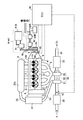
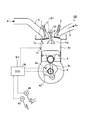
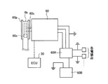
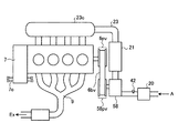
図1は、実施例1に係る内燃機関及びこの内燃機関が搭載される車両の補機例を示す説明図である。図2は、実施例1に係る内燃機関が備える一つの気筒に関する断面図である。まず、図1、2を用いて、この実施例に係る内燃機関の構成について説明する。図1に示すように、実施例1に係る内燃機関100は、4個の気筒1sを備えている。この内燃機関100は、乗用車やトラックその他の車両に搭載され、前記車両の動力源となる。図2に示すように、気筒1s内をピストン5が往復運動し、クランク軸6によってピストン5の往復運動が回転運動に変換される。このように、実施例1に係る内燃機関100は、複数の気筒を備えるレシプロ式の内燃機関である。しかし、本発明は過給機を備える内燃機関であれば適用でき、単気筒、多気筒問わない。また、過給機を備えていれば、火花点火式、ディーゼル式いずれの内燃機関でも適用でき、さらには、ロータリー式の内燃機関でもよい。以下の実施例で説明する内燃機関100は、レシプロ式の内燃機関であって、軽油等のディーゼル燃料を燃料として駆動されるディーゼル式の内燃機関である。
FIG. 1 is an explanatory diagram illustrating an example of an internal combustion engine according to the first embodiment and an auxiliary machine of a vehicle in which the internal combustion engine is mounted. FIG. 2 is a cross-sectional view of one cylinder included in the internal combustion engine according to the first embodiment. First, the configuration of the internal combustion engine according to this embodiment will be described with reference to FIGS. As shown in FIG. 1, the
図2に示すように、内燃機関100は、気筒1sの燃焼室1b内へ、ディーゼル燃料を噴射する燃料噴射弁4を備える。この内燃機関100は、いわゆる予備燃焼室を持たずに燃焼室1b内へ直接燃料Fを噴射する、いわゆる直噴ディーゼル機関であるが、本発明の適用対象はこれに限られるものではない。燃料噴射弁4は、コモンレール4Dに取り付けられている。コモンレール4D内には高圧ポンプで加圧されたディーゼル燃料が満たされており、各燃料噴射弁4へコモンレール4D内の燃料が供給される。
As shown in FIG. 2, the
また、内燃機関100は、過給機としてターボチャージャー(以下ターボという)50を備えている。ターボ50は、圧縮機51とタービン53と、両者を連結する軸52とを備えて構成される。タービン53は、内燃機関100の燃焼室1b内で燃焼した後の排ガスExにより駆動される。タービン53と圧縮機51とは軸52で連結されているので、圧縮機51はタービン53により駆動される。タービン53により駆動された圧縮機51は、吸気通路23から導入される空気Aを圧縮して内燃機関100の各気筒1s内へ送り込む。
The
気筒1sの燃焼室1b内には、内燃機関100の負荷KLや機関回転数NEに応じた時期及び必要な量で燃料噴射弁4から燃料Fが噴射される。燃料噴射弁4から噴射された燃料Fは燃焼室1b内で燃料噴霧Fmを形成する。この燃料噴霧Fmは、燃焼室1b内の圧縮された高温の空気Aにより自己着火し、燃焼する。なお、燃料Fは、吸気弁2が閉じている状態で、かつ内燃機関100の圧縮行程で噴射されるが、図2においては、燃焼室1b内への空気Aの導入と燃料Fの噴射とを説明するため、説明の便宜上、実際とは異なる状態を示している。
Fuel F is injected from the
燃料Fが燃焼する際に発生する圧力はピストン5に伝えられ、ピストン5を往復運動させる。ピストン5の往復運動はコネクティングロッド6cを介してクランク軸6に伝えられ、ここで回転運動に変換されて、内燃機関100の出力として取り出される。燃焼後の燃料Fは排ガスExとなり、排ガス弁3を通ってエキゾーストマニホールド9へ排出される。排ガスExは、触媒22で浄化されて空気中へ排出される。
The pressure generated when the fuel F burns is transmitted to the
内燃機関100の運転は、エンジンECU30によって制御される。エンジンECU30は、アクセル開度センサ46から取得したアクセル開度情報、及び回転数センサ44から取得した機関回転数NEとから、内燃機関100の要求トルクTqを計算する。エンジンECU30は、この要求トルクTqに基づき、内燃機関100の燃料噴射弁4から噴射する燃料Fの噴射量を決定する。このとき、エンジンECU30は、吸気温センサ42や冷却水温センサ41から吸入する空気Aの温度や内燃機関100の冷却水温を取得して、燃料Fの噴射量を補正する。そして、クランク角センサ40から取得したクランク角情報に基づいて、燃料噴射弁4の燃料噴射時期を制御する。また、エンジンECU30は、ブレーキセンサ43の信号を取得して、ブレーキの作動及び解除を判定する。これによって、実施例1においては、運転者の加速意思を検出する。
The operation of the
クランク軸6の出力は、減速機7で減速されてトルクが増大される。そして、クランク軸6の回転力によりドライブシャフト7oが駆動されて、内燃機関100が搭載される車両を進行させる。また、クランク軸6は、この内燃機関100が搭載される車両の補機を駆動する。ここでいう車両の補機とは、当該車両の運転上必要なすべての補機類を含む概念であり、内燃機関100の運転上必要な補機類も含む。このような補機類としては、例えば図1に示すオルタネータ(交流発電機)60や、車両用空調装置を構成するコンプレッサ61がある。
The output of the
次に、運転時の内燃機関100について説明する。エアクリーナ20でごみが取り除かれた空気Aは、ターボ50の圧縮機51で圧縮された後、吸気通路23を通ってインタークーラー21で冷却される。インタークーラー21で冷却された空気Aは、インテークマニホールド8を通って各気筒1sの燃焼室1b内へ送られる。各気筒1sの燃焼室1b内へ送られた空気は、ピストン5が圧縮上死点へ向かって移動することにより4MPa以上に圧縮され、600℃以上に昇温する。ここに、燃料噴射弁4からアクセル開度及び機関回転数に基づいて計算された燃料噴射量の燃料Fが噴射されて、燃焼する。燃料Fの燃焼圧力は、ピストン5、コネクティングロッド6c及びクランク軸6によって回転運動に変換され、出力としてクランク軸6から取り出される。燃焼後の燃料Fは排ガスExとなり、これは触媒22で浄化されて空気中へ排出される。
Next, the
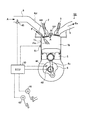
次に、本発明が適用できる他の内燃機関の例について説明する。次の説明では、適宜図1を参照されたい。図3は、火花点火式の直噴内燃機関の一例を示す説明図である。この内燃機関101は、火花点火式のレシプロ式内燃機関であり、気筒1sの燃焼室1b内へ直接燃料Fを噴射する、いわゆる直噴内燃機関である。この内燃機関101は、気筒1sの燃焼室1b内へ直接燃料Fを噴射して燃料噴霧Fmを形成する、直噴噴射弁4diを備える。この直噴噴射弁4diから内燃機関101の圧縮行程、あるいは吸気行程で燃料を噴射することにより、燃料Fを成層燃焼あるいは均質燃焼させて、内燃機関101を運転する。
Next, examples of other internal combustion engines to which the present invention can be applied will be described. In the following description, please refer to FIG. 1 as appropriate. FIG. 3 is an explanatory diagram showing an example of a spark ignition direct injection internal combustion engine. The
ターボ50で圧縮され、吸気通路23を通ってインテークマニホールド8に導かれた空気Aは、吸気弁2を通って燃焼室1b内へ導入される。そして、直噴噴射弁4diから燃焼室1b内へ導入された空気Aへ燃料Fが噴射される。直噴噴射弁4diから噴射された燃料Fは、燃料噴霧Fmとなって周囲の空気Aを巻き込みながら混合気を形成する。点火プラグSPでこの混合気に着火することにより前記混合気を燃焼させる。前記混合気の燃焼圧力は、ピストン5に伝えられ、ピストン5を往復運動させる。ピストン5の往復運動はコネクティングロッド6cを介してクランク軸6に伝えられ、ここで回転運動に変換されて、内燃機関101の出力として取り出される。燃焼後の燃料Fは排ガスExとなり、排ガス弁3を通って排ガス通路を構成するエキゾーストマニホールド9へ排出される。排ガスExは、触媒22で浄化されて空気中へ排出される。
The air A compressed by the
内燃機関101の運転は、エンジンECU30により制御される。エンジンECU30は、アクセル開度センサ46から取得したアクセル開度情報、エアフローセンサ45から取得した吸入空気量、及び回転数センサ44から取得した機関回転数NEに基づいて、直噴噴射弁4diから噴射する燃料Fの噴射量を決定する。このとき、エンジンECU30は、吸気温センサ42や冷却水温センサ41から吸気温度や内燃機関101の水温を取得して、燃料Fの噴射量を補正する。そして、クランク角センサ40から取得したクランク角情報に基づいて、直噴噴射弁4diの燃料噴射時期を制御する。また、エンジンECU30は、ブレーキセンサ43の信号を取得して、ブレーキの作動及び解除を判定する。これによって、運転者の加速意思を検出する。
The operation of the
本発明の適用できる火花点火式内燃機関は、この内燃機関101に限られない。例えば、さらに、インテークマニホールド8内へ燃料を噴射するポート噴射弁4piを備える、いわゆるデュアル燃料噴射弁方式の火花点火式内燃機関に対しても本発明は適用できる。また、インテークマニホールド8内へ燃料を噴射するポート噴射弁4piのみを備える火花点火式内燃機関に対しても本発明は適用できる。
The spark ignition internal combustion engine to which the present invention can be applied is not limited to the
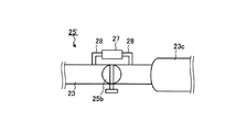
図4−1、図4−2は、火花点火式内燃機関における吸気量の制御手段の説明図である。図4−1には、吸気通路23に電子スロットル弁25を備えるものを示す。内燃機関101の出力を制御する場合には、アクセルの開度を調整することにより吸気通路23の途中に設けられた電子スロットル弁25のバタフライバルブ25bの開度を調整する。これにより、内燃機関101の吸気量を調整するとともに燃料噴射量を調整して、内燃機関101の出力を制御する。電子スロットル弁25は、アクセルの開度を回転角センサ25cにより電気信号に変換し、この電気信号によりアクチュエータ25aでバタフライバルブ25bを開閉するものである。電子スロットル弁25を用いる場合は、エンジンECU30によりアクチュエータ25aの開度を直接調整して、内燃機関101のアイドリング回転数を一定に制御することができる。
FIGS. 4A and 4B are explanatory diagrams of intake air amount control means in the spark ignition internal combustion engine. FIG. 4A shows an
図4−2には、吸気通路23にワイヤー式のスロットル弁25'を備えるものを示す。このスロットル弁25'は、吸気通路23にバイパス通路28が設けられており、このバイパス通路28には、ISC(Idling Speed Control)バルブ27が備えられている。内燃機関101がアイドリング状態のときには、バタフライバルブ25bが閉じられる。そして、内燃機関101にはバイパス通路28を通って空気が供給される。このとき、エンジンECU30がISCバルブ27の開度を調整することにより、内燃機関101のアイドリング回転数を一定に制御する。
FIG. 4B shows the
図5−1は、オルタネータの駆動部分を示す拡大図である。オルタネータ60は、車両の走行中に、前記車両や内燃機関100が必要とする電気を発生する。オルタネータ60は、内燃機関100のクランク軸6に取り付けられたクランク軸プーリ6p、これに掛けられたベルト6b、及びオルタネータプーリ60pを介して駆動されて、三相の交流電気を発電する。このオルタネータ60は、オルタネータプーリ60pとオルタネータ駆動シャフト60sとの間に、補機断続手段である電磁クラッチ60cが内蔵されており、エンジンECU30からの指令により、両者を断続できるように構成される。発電の必要に応じて前記電磁クラッチ60cを接続することにより、必要なときにオルタネータ60から電力を発生させることができる。
FIG. 5A is an enlarged view showing a drive portion of the alternator. The
オルタネータ60で発電された三相交流電気は、レギュレータ60Rで一定電圧の直流電気に変換されて、電装品に供給されたり、バッテリー60Bを充電したりする。電装品としては、例えば、パワーウィンドウ、電動ミラー、電動式のパワーステアリング、車両用空調装置のファン等がある。火花点火式の内燃機関101であれば、点火プラグに電力を供給するイグニッションシステムがある。
The three-phase alternating current electricity generated by the
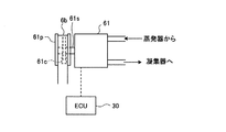
図5−2は、コンプレッサの駆動部分を示す拡大図である。車両用空調装置61ACを構成するコンプレッサ61は、内燃機関100のクランク軸6に取り付けられたクランク軸プーリ6p、これに掛けられたベルト6b及びコンプレッサプーリ61pを介して駆動される。そして、他の車両用空調装置構成部分61Bに含まれる蒸発器から受け取った冷媒を圧縮して凝縮器へ圧送する。これにより、蒸発器で気化した液体を凝縮器で液体に戻して、冷房サイクルを実現する。
FIG. 5-2 is an enlarged view showing a drive portion of the compressor. The
このコンプレッサ61は、コンプレッサプーリ61pとコンプレッサ駆動シャフト61sとの間に、補機断続手段である電磁クラッチ61cが内蔵されており、エンジンECU30からの指令により、両者を断続できるように構成される。車両用空調装置を使用する際に前記電磁クラッチ61cを接続することにより、コンプレッサ61を作動させて車両用空調装置を使用することができる。
The
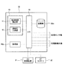
次に、実施例1に係る内燃機関の制御装置について説明する。図6は、実施例1に係る内燃機関の制御装置の構成を示す説明図である。ここで、実施例1に係る内燃機関の制御方法は、本発明の内燃機関の制御装置10によって実現できる。内燃機関の制御装置10は、エンジンECU30に組み込まれて構成されている。なお、エンジンECU30とは別個に、この実施例に係る内燃機関の制御装置10を用意し、これをエンジンECU30に接続してもよい。そして、この実施例に係る内燃機関の制御方法を実現するにあたっては、エンジンECU30が備える内燃機関100等の制御機能を、前記内燃機関の制御装置10が利用できるように構成してもよい。
Next, an internal combustion engine control apparatus according to
内燃機関の制御装置10は、加速意思検出部11と、過給圧上昇部12とを含んで構成される。これらが、この実施例に係る内燃機関の制御方法を実行する部分となる。加速意思検出部11と、過給圧上昇部12とは、内燃機関の制御装置10の入出力ポート(I/O)19を介して接続される。これにより、加速意思検出部11と、過給圧上昇部12とは、それぞれ双方向でデータをやり取りできるように構成される。なお、装置構成上の必要に応じて片方向でデータを送受信するように構成してもよい(以下同様)。
The
内燃機関の制御装置10とエンジンECU30の処理部30pと記憶部30mとは、エンジンECU30に備えられる入出力ポート(I/O)19を介して接続されており、これらの間で相互にデータをやり取りすることができる。これにより、内燃機関の制御装置10はエンジンECU30が有する内燃機関100等の負荷や機関回転数その他の内燃機関の運転制御データを取得したり、内燃機関の制御装置10の制御をエンジンECU30の内燃機関の運転制御ルーチンに割り込ませたりすることができる。また、入出力ポート(I/O)19には、AC(Air Conditioner)制御装置31やAT(Automatic Transmission)コントローラ32が接続されている。これにより、内燃機関の制御装置10やエンジンECU30の処理部30pは、AC制御装置31やATコントローラからの制御信号を取得して制御に利用したり、内燃機関の制御装置10等の制御をAC制御装置31等の運転制御ルーチンに割り込ませたりすることができる。
The
また、入出力ポート(I/O)19には、アクセル開度センサ46、回転数センサ44、ブレーキセンサ43その他の、内燃機関100等の運転状態に関する情報を取得する各種センサ類が接続されている。これにより、エンジンECU30や内燃機関の制御装置10は、内燃機関100等の運転制御に必要な情報を取得することができる。また、入出力ポート(I/O)19には、オルタネータプーリ60pやコンプレッサプーリ61pに内蔵された電磁クラッチ60c、61cその他の制御対象が接続されており、内燃機関の制御装置10の過給圧上昇部12やエンジンECU30の処理部30pからの制御信号によりこれらの動作を制御できるように構成されている。
The input / output port (I / O) 19 is connected to various sensors for acquiring information related to the operating state of the
記憶部30mには、実施例1に係る内燃機関の制御方法の処理手順を含むコンピュータプログラムや、内燃機関100の運転制御に用いる燃料噴射量のデータマップ等が格納されている。ここで、記憶部30mは、RAM(Random Access Memory)のような揮発性のメモリ、フラッシュメモリ等の不揮発性のメモリ、あるいはこれらの組み合わせにより構成することができる。また、内燃機関の制御装置10やエンジンECU30の処理部30pは、メモリ及びCPUにより構成することができる。
The
上記コンピュータプログラムは、加速意思検出部11や過給圧上昇部12へすでに記録されているコンピュータプログラムとの組み合わせによって、この実施例に係る内燃機関の制御方法の処理手順を実現できるものであってもよい。また、この内燃機関の制御装置10は、前記コンピュータプログラムの代わりに専用のハードウェアを用いて、加速意思検出部11、過給圧上昇部12の機能を実現するものであってもよい。次に、この内燃機関の制御装置10を用いて、実施例1に係る内燃機関の制御方法を実現する手順を説明する。なお、この説明にあたっては、適宜図1〜6を参照されたい。また、制御の対象とする内燃機関は、ディーゼル式の内燃機関100であるが、火花点火式の内燃機関101でも同様である。
The computer program can realize the processing procedure of the control method of the internal combustion engine according to this embodiment by combining with the computer program already recorded in the acceleration
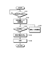
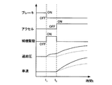
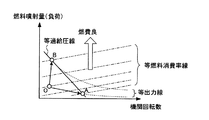
図7は、実施例1に係る内燃機関の制御方法の手順を示すフローチャートである。図8は、実施例1に係る内燃機関の制御方法におけるタイミングチャートである。図9は、内燃機関の等過給圧と等燃料消費率と等出力とを、燃料噴射量(負荷)と機関回転数との関係において表した説明図である。実施例1に係る内燃機関の制御方法を実行するにあたり、実施例1に係る内燃機関の制御装置10が備える加速意思検出部11は、車両が加速する前に、運転者の加速意思を検知したか否かを判定する(ステップS101)。
FIG. 7 is a flowchart illustrating a procedure of the control method of the internal combustion engine according to the first embodiment. FIG. 8 is a timing chart of the internal combustion engine control method according to the first embodiment. FIG. 9 is an explanatory diagram showing the equal supercharging pressure, the equal fuel consumption rate, and the equal output of the internal combustion engine in relation to the fuel injection amount (load) and the engine speed. In executing the control method for an internal combustion engine according to the first embodiment, the acceleration
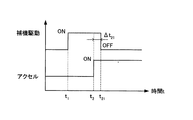
加速意思は、例えば、図8に示すように、運転者が車両の制動装置であるブレーキを解除、すなわち制動を解除(OFF;t=t1)したときに、加速意思があるものと判断できる。このとき、より確実に加速意思を検出するために、フットブレーキ及びサイドブレーキの両方が解除されたときに、加速意思があるものと判定することが好ましい。加速意思の検出にブレーキの解除を用いれば、簡易かつ確実に加速意思を検出できるので好ましい。ブレーキの解除は、加速意思検出部11が、図2、図3に示すブレーキセンサ43から、ブレーキ解除信号を検出することにより検知できる。また、他の判定例として、例えば、図6に示すATコントローラ32からダウンシフトの情報を受け取ったときには、運転者の加速意思があると判断することもできる。
For example, as shown in FIG. 8, the intention to accelerate can be determined to be an intention to accelerate when the driver releases the brake, which is the braking device of the vehicle, that is, releases the brake (OFF; t = t 1 ). . At this time, in order to detect the acceleration intention more reliably, it is preferable to determine that there is an acceleration intention when both the foot brake and the side brake are released. It is preferable to use the release of the brake to detect the acceleration intention because the acceleration intention can be detected easily and reliably. The release of the brake can be detected by the acceleration
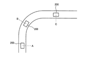
図10、図11は、運転者の加速意思を検出する手段の他の例を示す説明図である。図10は、車両200がカーブを通過している間(図10中A、B点)は加速意思がないものと判定し、車両200がカーブの出口(図10中C点)に到達したら、加速の意思が検知されたと判定する。車両200とカーブとの位置関係は、例えばカーナビゲーションシステムからの情報により取得する。そして、車両200の現時点における位置と先行道路情報とから、車両200がカーブの出口に到達した時点で、運転者の加速意思が検知されたと判定する。
10 and 11 are explanatory diagrams showing other examples of means for detecting the driver's intention to accelerate. FIG. 10 determines that there is no intention to accelerate while the
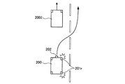
図11に示す例は、運転者が先行車両200lを追い越そうとしたときに、加速意思を検知したと判定する例を示している。この例では、車両200に搭載されている前方監視センサ202と、カーナビゲーションシステムの情報とを利用する。例えば、カーナビゲーションシステムからの情報から、車両200が追い越し可能道路を走行中であって、かつ先行車両200lが存在する場合、右ウインカー201rが指示されたら運転者は先行車両200lを追い越そうとしていると判定する。このとき、円滑に追い越しを完了させるため、運転者に加速意思があると判断する。
The example shown in FIG. 11 shows an example in which it is determined that an intention to accelerate is detected when the driver tries to pass the preceding vehicle 200l. In this example, the
また、先行車両200lが存在しない場合であっても、カーナビゲーションシステムから、例えば、車両200が自動車専用道路への合流しようとしている情報を検知したら、車両200の運転者には加速意思があると判定することもできる。さらに、カーナビゲーションシステムから、例えば、車両200の先行道路に登坂路が存在する場合にも、車両200の運転者には加速意思があると判定することもできる。このように、運転者の加速意思は、車両のハードウェアから検出される各種信号に基づいて判断してもよいし、カーナビゲーションシステム等からの自車の走行状況に基づいて判断してもよい。
Further, even if the preceding vehicle 200l does not exist, if the
加速意思検出部11が運転者の加速意思を検知しなかった場合、(ステップS101;No)、加速意思検出部11は再び運転者の加速意思を検出するまで監視を続ける。加速意思検出部11が運転者の加速意思を検知した場合、(ステップS101;Yes)、過給圧上昇部12は、内燃機関100により補機を駆動する(ステップS102)。例えば、補機として図5−1に示すオルタネータ60を駆動する場合、オルタネータプーリ60pとオルタネータ駆動シャフト60sとの間の電磁クラッチ60cを接続する。あるいは、補機として図5−2に示すコンプレッサ61を駆動する場合、コンプレッサプーリ61pとコンプレッサ駆動シャフト61sとの間の電磁クラッチ61cを接続する。これにより、内燃機関100の負荷を増加させる。このとき、内燃機関100の機関回転数は、補機との接続前とほぼ一定に維持する。これは、内燃機関100の機関回転数と要求トルクとから、エンジンECU30により必要な燃料噴射量を求めることで実現できる。また、火花点火式の内燃機関101であれば、図4−2に示すISCバルブ27を利用したり、図4−1に示す電子スロットル弁25を利用したりすることにより実現できる。
When the acceleration
図12は、実施例1に係る内燃機関の制御方法における燃料噴射量の制御例を示す説明図である。内燃機関100によりオルタネータ60やコンプレッサ61その他の補機を駆動する際には、内燃機関100と補機とを接続する。両者を接続する瞬間には、急激トルク変動が発生するため、内燃機関100の回転数が急激に低下して、運転者に違和感を与えるおそれがある。これを抑制するため、運転者の加速意思を検知して内燃機関100と補機とを接続するタイミング(t=t1)では、補機駆動に必要な内燃機関100の燃料噴射量q2よりも大きい燃料噴射量q3で燃料を噴射する。これにより、内燃機関100と補機とを接続する際の急激なトルク変動を抑制する。そして、内燃機関100と補機とが接続されたら、内燃機関100の燃料噴射量を、徐々に補機駆動に必要な内燃機関100の燃料噴射量q2とする。
FIG. 12 is an explanatory diagram illustrating a control example of the fuel injection amount in the control method of the internal combustion engine according to the first embodiment. When the
ここで、負荷が一定の場合には、機関回転数が大きいほど燃料消費率は悪化する。このため、ターボ50の過給圧を上昇させるために内燃機関100を図9のA点における条件で運転すると、負荷がほぼ一定で機関回転数が上昇することになる。その結果、内燃機関100の機関回転数が上昇する結果、燃料消費率は悪化してしまう。
Here, when the load is constant, the fuel consumption rate deteriorates as the engine speed increases. For this reason, when the
一方、実施例1に係る内燃機関の制御では、内燃機関100で補機を駆動して内燃機関100の負荷を上昇させることにより、ターボ50の過給圧を上昇させる。なお、内燃機関100の負荷を上昇させる場合、内燃機関100はディーゼル式の内燃機関なので、燃料噴射弁4からの燃料噴射量を増加させる。実施例1に係る内燃機関の制御では、運転者の加速意思を検知するまでは内燃機関100が図9のO点における条件で運転されていた場合、上記制御により内燃機関100は図9のB点における条件で運転される。すなわち、運転者の加速意思が検出されてから実際に加速を開始するまでの間は、内燃機関100の機関回転数はほぼ一定で、負荷が大きくなる状態で運転される。
On the other hand, in the control of the internal combustion engine according to the first embodiment, the boost pressure of the
ここで、機関回転数が一定の場合には、負荷(ディーゼル機関においては燃料噴射量)が大きいほど燃料消費率は向上する。したがって、実施例1に係る内燃機関の運転制御によれば、燃料消費率の良好な条件下で内燃機関100を運転できる。同時に、図8に示すように、加速のための過給圧を上昇させ、加速性能を向上させることができる。なお、図9に示すように、内燃機関100の負荷上昇にともなって出力も増大するが、その出力増大分(線分OB)は、内燃機関100によって駆動される補機(例えばオルタネータ60やコンプレッサ61)により回収できるので、燃料消費の悪化を抑制することができる。特に、発電機であるオルタネータにより前記出力増大分を回収する場合、使いやすい電気エネルギーとして回収できるので、回収した内燃機関の出力増加分を使いやすい形で利用することができる。
Here, when the engine speed is constant, the fuel consumption rate improves as the load (the fuel injection amount in a diesel engine) increases. Therefore, according to the operation control of the internal combustion engine according to the first embodiment, the
図8に示す過給圧及び車速の時間変化は、実線が実施例1に係るものであり、点線が実施例1の制御を適用しないものである。図8に示すように、実施例1に係る内燃機関の運転制御によれば、運転者の加速意思を検知したら、速やかにターボ50の過給圧が上昇することがわかる。そして、実際に加速を開始してからは、実施例1に係る内燃機関の運転制御は、当該制御を適用しない場合と比較して、加速性能が向上することがわかる。
In the time change of the supercharging pressure and the vehicle speed shown in FIG. 8, the solid line relates to the first embodiment, and the dotted line does not apply the control of the first embodiment. As shown in FIG. 8, according to the operation control of the internal combustion engine according to the first embodiment, it is understood that when the driver's intention to accelerate is detected, the supercharging pressure of the
加速意思検出部11は、実際に加速が開始されるか否かを判定する(ステップS103)。実際に加速が開始されるか否かは、アクセルがONにされた時点(t=t2)で加速開始と判断することができる。これは、例えば、アクセル開度センサ46からのアクセル開度信号を加速意思検出部11が取得し、当該信号値が所定の閾値を越えたらアクセルがONにされたと判断する。
The acceleration
加速を開始しない場合(ステップS103;No)、過給圧上昇部12は、実際に加速が開始されるまで(t=t2)、内燃機関100による補機の駆動を継続する(ステップS104)。加速を開始する場合(ステップS103;Yes)、過給圧上昇部12は、図8に示すように、内燃機関100による補機の駆動を停止する(ステップS105)。その後、車両は加速を開始する(ステップS106)。このように、車両の加速開始を受けて、前記補機の駆動を停止すれば、燃料消費を抑えつつ、滑らかに加速へ移行できる。
When acceleration is not started (step S103; No), the boost
図13は、内燃機関による補機の駆動を停止する際の一例を示す説明図である。図8に示すように、アクセルがONにされた時点(t=t2)で内燃機関100による補機の駆動を停止してもよいが、図13に示すように、アクセルがONにされた時点からΔt21(=t21−t2)経過してから、内燃機関100による補機の駆動を停止してもよい。このようにすることで、アクセルをONしたときに、内燃機関100による補機の駆動を停止することによる過給圧が低下するおそれを低減できるので、速やかに加速に移行できる。
FIG. 13 is an explanatory diagram showing an example when driving of the auxiliary machine by the internal combustion engine is stopped. As shown in FIG. 8, the driving of the auxiliary machine by the
実施例1に係る内燃機関の制御は、特に、高過給かつ小排ガス量のディーゼル機関には好ましい。このような内燃機関は、風量の大きいタービンを用いるため、過給圧が上昇するまでに時間を要するからである。実施例1に係る内燃機関の制御によれば、燃料消費の悪化を抑制して、加速準備のために過給圧を上昇させることができる。また、実施例1に係る内燃機関の制御は、停止から加速する場合、走行中に加速する場合、いずれに対しても適用できる。 The control of the internal combustion engine according to the first embodiment is particularly preferable for a diesel engine having a high supercharge and a small exhaust gas amount. This is because such an internal combustion engine uses a turbine with a large air volume, and thus it takes time until the boost pressure increases. According to the control of the internal combustion engine according to the first embodiment, it is possible to suppress the deterioration of fuel consumption and increase the supercharging pressure in preparation for acceleration. Further, the control of the internal combustion engine according to the first embodiment can be applied to any of the case where acceleration is performed from a stop and the case where acceleration is performed during traveling.
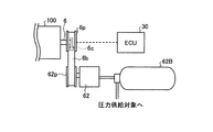
次に、実施例1に適用できる補機の他の例を説明する。図14、図15、図16は、実施例1に適用できる補機の他の例を示す説明図である。図14に示す補機は、コンプレッサ62と圧力容器62Bとの組み合わせにより構成される。この補機は、コンプレッサ62により気体を圧縮して圧力容器62Bに蓄えるものである。コンプレッサ62は、内燃機関100のクランク軸6に取り付けられたクランク軸プーリ6pと、コンプレッサプーリ62pとに掛けられたベルト6bを介して内燃機関100により駆動される。
Next, another example of the auxiliary machine applicable to the first embodiment will be described. FIGS. 14, 15, and 16 are explanatory diagrams illustrating other examples of the auxiliary machine that can be applied to the first embodiment. The auxiliary machine shown in FIG. 14 is configured by a combination of a
クランク軸プーリ6pとクランク軸6との間には、補機断続手段である電磁クラッチ6cが設けられている。運転者の加速意思を検出した際には、エンジンECU30に内蔵されている内燃機関の制御装置10がこの電磁クラッチ6cを接続することにより、コンプレッサ62を駆動する。これにより、圧力容器62B内へ気体(例えば空気)を送り込み、高圧の気体として圧力容器62B内へ蓄える。そして、圧力容器62B内の高圧気体の持つエネルギーを、例えば内燃機関100の駆動力アシストとして使用することができる。このようにして、補機を駆動する際における内燃機関100の出力増大分を回収して、燃料消費の悪化を抑制することができる。
Between the
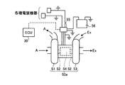
図15は、過給気に電動アシストターボ50eを用いて、電動アシストターボ50eのモータ54を補機として用いる例を示す。電動アシストターボ50eは、タービン53と、圧縮機51と、モータ54と、軸52とで構成される。軸52は、タービン53及び圧縮機51の軸も兼ねており、タービン53と圧縮機51とがモータ軸により連結される。モータ54は誘導電動機であり、電源によって駆動されるとともに、タービン53に内燃機関の排ガスExを供給すれば、発電機としても機能する。
FIG. 15 shows an example in which the
運転者の加速意思を検出した際には、エンジンECU30に内蔵されている内燃機関の制御装置10はモータ54を発電機として機能させる。すなわち、電動アシストターボ50eを構成するモータ54を補機として、これを内燃機関100により駆動する。モータ54を発電機として機能させることにより得られた電力は、レギュレータ55で直流に変換され、バッテリー56へ充電される。これにより、補機を駆動する際における内燃機関100の出力増大分を回収して、燃料消費の悪化を抑制することができる。
When the driver's intention to accelerate is detected, the internal combustion
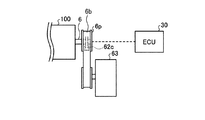
図16は、補機としてフライホイール63を用い、内燃機関100の出力増大分をフライホイール63へ慣性力として蓄える例を示す。フライホイール63は、内燃機関100のクランク軸6に取り付けられたクランク軸プーリ6pと、フライホイールプーリ62pとに掛けられたベルト6bを介して内燃機関100により駆動される。
FIG. 16 shows an example in which a
クランク軸プーリ6pとクランク軸6との間には、補機断続手段である電磁クラッチ6cが設けられている。運転者の加速意思を検出した際には、エンジンECU30に内蔵されている内燃機関の制御装置10がこの電磁クラッチ62cを接続することにより、フライホイール63を駆動する。そして、実際に加速に移行したら、前記電磁クラッチを解除する。これにより、補機を駆動する際における内燃機関100の出力増大分を、フライホイール63へ慣性力として蓄えることができる。フライホイール63へ蓄えた前記出力増大分は、例えば、内燃機関100の駆動力アシストとして使用することができる。このようにして、補機を駆動する際における内燃機関100の出力増大分を回収して、燃料消費の悪化を抑制することができる。
Between the
以上、実施例1によれば、車両の加速前に運転者の加速意思を検出した場合には、車両に搭載される補機を内燃機関によって駆動させて内燃機関の負荷を増加させ、過給圧を上昇させる。これにより、内燃機関は低回転、高負荷の運転条件で運転されるので、燃料消費率が良好な条件下で運転でき、燃料消費の悪化を抑制できる。また、負荷増加による内燃機関の出力増加分は補機により回収できるので、燃料消費の悪化を抑制できる。その結果、燃料消費の悪化を抑制しつつ、速やかに過給圧を上昇させて、加速性能を向上させることができる。なお、実施例1で開示した構成は、以下の実施例でも適宜適用できる。また、実施例1に開示した構成と同一の構成を備えるものは、実施例1と同様の作用、効果を奏する。 As described above, according to the first embodiment, when the driver's intention to accelerate is detected before the acceleration of the vehicle, the auxiliary machine mounted on the vehicle is driven by the internal combustion engine to increase the load of the internal combustion engine, Increase pressure. As a result, the internal combustion engine is operated under low-rotation and high-load operating conditions, so that it can be operated under conditions with a good fuel consumption rate, and deterioration of fuel consumption can be suppressed. Further, since the increase in the output of the internal combustion engine due to the load increase can be recovered by the auxiliary machine, deterioration of fuel consumption can be suppressed. As a result, the acceleration performance can be improved by quickly increasing the supercharging pressure while suppressing deterioration of fuel consumption. The configuration disclosed in the first embodiment can be applied as appropriate in the following embodiments. Moreover, what has the same structure as the structure disclosed in Example 1 has the same operations and effects as Example 1.
実施例2は、実施例1とほぼ同様の構成であるが、過給手段に機械式の過給機(いわゆるスーパーチャージャー)を用い、これを過給手段として用いるとともに、過給圧を増加させる際に、内燃機関の出力増加分を回収する補機としても使用する点が異なる。他の構成は実施例1と同様なのでその説明を省略するとともに、同一の構成要素には同一の符号を付す。なお、実施例2に係る内燃機関の運転制御は、実施例1に係る内燃機関の制御装置により実現できる。図17は、実施例2に係る内燃機関の全体構成を示す説明図である。図18、図19−1、図19−2は、実施例2に係る過給手段を駆動する動力伝達系の説明図である。 The second embodiment has substantially the same configuration as that of the first embodiment, but a mechanical supercharger (so-called supercharger) is used as the supercharging means, and this is used as the supercharging means and the supercharging pressure is increased. However, the difference is that it is also used as an auxiliary machine for recovering the increased output of the internal combustion engine. Since the other configuration is the same as that of the first embodiment, the description thereof is omitted, and the same component is denoted by the same reference numeral. The operation control of the internal combustion engine according to the second embodiment can be realized by the control device for the internal combustion engine according to the first embodiment. FIG. 17 is an explanatory diagram illustrating an overall configuration of the internal combustion engine according to the second embodiment. 18, 19-1, and 19-2 are explanatory diagrams of a power transmission system that drives the supercharging unit according to the second embodiment.
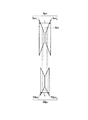
この内燃機関は、機械式の過給機(以下スーパーチャージャー:SCという)58を備える。SC58は、コンプレッサ58cとSC可変速プーリ58pvとで構成される。内燃機関102のクランク軸6には、クランク軸可変速プーリ6pvが取り付けられている。そして、SC58のコンプレッサ58cは、前記クランク軸可変速プーリ6pvと、SC可変速プーリ58pvとに掛けられたVベルト6bvを介して内燃機関102により駆動される。
The internal combustion engine includes a mechanical supercharger (hereinafter referred to as a supercharger: SC) 58. The
図18に示すように、クランク軸可変速プーリ6pvは、円錐台形状の第1クランクプーリ6pv1の小径側と、同じく円錐台形状の第2クランクプーリ6pv2の小径側とを向かい合わせて構成される。そして、第1及び第2クランクプーリ6pv1、6pv2のプーリ間距離l1を変化させることができるように構成される。同様に、SC可変速プーリ58pvは、円錐台形状の第1SCプーリ58pv1の小径側と、第2SCプーリ58pv2の小径側とを向かい合わせて構成される。そして、第1及び第2SCプーリ58pv1、58pv2のプーリ間距離l2を変化させることができるように構成される。なお、両プーリ間距離l1、l2は、エンジンECU30内に備えられる内燃機関の制御装置10(図6)により制御される。
As shown in FIG. 18, the crankshaft variable speed pulley 6Pv is facing the small diameter side of the first crank pulley 6Pv 1 frustoconical, also a second crank pulley 6Pv 2 of the small diameter side of the truncated cone structure Is done. The first and second crank pulleys 6pv 1 and 6pv 2 are configured to be able to change the inter-pulley distance l 1 . Similarly, SC variable speed pulley 58Pv is constituted by opposed and the small diameter side of the 1SC pulley 58Pv 1 frustoconical, of the 2SC pulley 58Pv 2 and the small diameter side. The inter-pulley distance l 2 of the first and second SC pulleys 58pv 1 and 58pv 2 can be changed. Note that the distances between the pulleys l 1 and l 2 are controlled by the control device 10 (FIG. 6) of the internal combustion engine provided in the
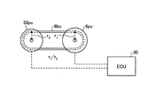
このように構成されたクランク軸可変速プーリ6pvと、SC可変速プーリ58pvとに、Vベルト6bvが掛けられている。図19−1、図19−2は、プーリ間距離を変更した場合の回転数比を示す説明図である。内燃機関102の運転中にSC58を駆動しているとき、プーリ間距離l1及びl2を変化させることにより、クランク軸可変速プーリ6pvにおけるVベルト6bvの回転半径と、SC可変速プーリ58pvにおけるVベルト6bvの回転半径とをそれぞれ変更することができる。これにより、クランク軸可変速プーリ6pvと、SC可変速プーリ58pvとの回転数比を連続的に変更できる。
The V-belt 6bv is hung on the crankshaft variable speed pulley 6pv and the SC variable speed pulley 58pv thus configured. FIGS. 19A and 19B are explanatory diagrams illustrating the rotation speed ratio when the distance between the pulleys is changed. When the
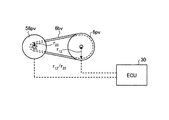
例えば、図19−1に示す例では、クランク軸可変速プーリ6pvにおけるVベルト6bvの回転半径r1と、SC可変速プーリ58pvにおけるVベルト6bvの回転半径r2とは、ほぼ同じ大きさである。このときの回転数比は、r1/r2(≒1)である。内燃機関102の機関回転数を変更することなしに、SC58の駆動回転数を大きくするためには、クランク軸可変速プーリ6pvにおけるVベルト6bvの回転半径を、SC可変速プーリ58pvにおけるVベルト6bvの回転半径よりも大きくすればよい。この場合、内燃機関の制御装置10により、第1及び第2クランクプーリ6pv1、6pv2のプーリ間距離l1をより小さく、第1及び第2SCプーリ58pv1、58pv2のプーリ間距離l2をより大きくする。これにより、図19−2に示すように、クランク軸可変速プーリ6pvにおけるVベルト6bvの回転半径r12は、SC可変速プーリ58pvにおけるVベルト6bvの回転半径r22よりも大きくなる。このときの回転数比は、r12/r22(>1)である。
For example, in the example shown in FIG. 19A, the rotation radius r 1 of the V belt 6bv in the crankshaft variable speed pulley 6pv and the rotation radius r 2 of the V belt 6bv in the SC variable speed pulley 58pv are substantially the same size. is there. The rotation speed ratio at this time is r 1 / r 2 (≈1). In order to increase the drive speed of the
運転者の加速意思を検出した際には、エンジンECU30に内蔵されている内燃機関の制御装置10は、クランク軸可変速プーリ6pvにおけるVベルト6bvの回転半径r12は、SC可変速プーリ58pvにおけるVベルト6bvの回転半径r22よりも大きくなるように制御する。これにより、SC58は、加速意思を検出する前よりも大きい回転数で駆動されるので、過給圧を増加させることができる。すなわち、SC58は、内燃機関102から、より多くの駆動力を与えられることになり、内燃機関102の負荷はそれだけ増加する。このとき、SC58を駆動する内燃機関102の機関回転数は、加速意思を検出する前と変化はないが、内燃機関102の負荷は、加速意思検出前よりも増加している。ここで、機関回転数が一定の場合には、負荷が大きいほど燃料消費率は向上する。したがって、実施例2によれば、過給圧を上昇させるため、機関回転数を増加させる場合と比較して、燃料消費率の良好な条件下で内燃機関102を運転できる。これにより、運転者の加速意思を検出した場合には、加速のための過給圧を上昇させ、実際に加速を開始し他場合における加速性能を向上させることができるとともに、燃料消費の悪化を抑制することができる。
Upon detecting the acceleration intention of the driver, the
以上のように、本発明に係る内燃機関及び内燃機関の制御装置、並びに内燃機関の制御方法は、過給機を備える内燃機関に有用であり、特に、燃料消費の悪化を抑制しつつ、ドライバビリティを向上させることに適している。 As described above, the internal combustion engine, the control device for the internal combustion engine, and the control method for the internal combustion engine according to the present invention are useful for the internal combustion engine including the supercharger, and in particular, the driver while suppressing the deterioration of the fuel consumption. It is suitable for improving the performance.
1b 燃焼室
1s 気筒
4 燃料噴射弁
4D コモンレール
4di 直噴噴射弁
4pi ポート噴射弁
5 ピストン
6 クランク軸
10 内燃機関の制御装置
11 加速意思検出部
12 過給圧上昇部
30 エンジンECU
50 ターボ(ターボチャージャー)
51 圧縮機
53 タービン
60 オルタネータ(交流発電機)
60c、61c、62c 電磁クラッチ
61 コンプレッサ
100、101、102 内燃機関
DESCRIPTION OF
50 Turbo (turbocharger)
51
60c, 61c, 62c Electromagnetic clutch 61
Claims (10)
前記車両の加速前に前記車両の運転者の加速意思を検出した場合には、前記車両に搭載される補機を駆動することによって負荷を増加させ、前記過給機の過給圧を上昇させることを特徴とする内燃機関。 An internal combustion engine that includes a supercharger and is mounted on a vehicle and serves as a power source for the vehicle.
When the driver's intention to accelerate is detected before the vehicle is accelerated, the load is increased by driving an auxiliary device mounted on the vehicle, and the supercharging pressure of the supercharger is increased. An internal combustion engine characterized by that.
前記車両の運転者の加速意思を検出する加速意思検出部と、
前記加速意思検出部が前記車両の加速前に運転者の加速意思を検出した場合には、前記車両に搭載される補機を前記内燃機関で駆動させることにより前記過給機の過給圧を上昇させる過給圧上昇部と、
を含んで構成されることを特徴とする内燃機関の制御装置。 A turbocharger and an internal combustion engine mounted on a vehicle and serving as a power source for the vehicle;
An acceleration intention detection unit for detecting an acceleration intention of a driver of the vehicle;
When the acceleration intention detection unit detects the driver's intention to accelerate before acceleration of the vehicle, the boost pressure of the supercharger is increased by driving an auxiliary machine mounted on the vehicle with the internal combustion engine. A boost pressure increasing section to increase;
A control apparatus for an internal combustion engine, comprising:
前記車両の運転者の加速意思を検出する手順と、
前記車両の加速前に運転者の加速意思を検出した場合には、前記車両に搭載される補機を前記内燃機関で駆動することにより前記過給機の過給圧を上昇させる手順と、
を含むことを特徴とする内燃機関の制御方法。 In controlling an internal combustion engine that includes a supercharger and is mounted on a vehicle and serves as a power source of the vehicle,
Detecting a driver's intention to accelerate the vehicle;
A procedure for increasing the supercharging pressure of the supercharger by driving an auxiliary machine mounted on the vehicle with the internal combustion engine when detecting the driver's intention to accelerate before accelerating the vehicle;
A control method for an internal combustion engine comprising:
Priority Applications (1)
| Application Number | Priority Date | Filing Date | Title |
|---|---|---|---|
| JP2004116992A JP4345555B2 (en) | 2004-04-12 | 2004-04-12 | Control device for internal combustion engine and control method for internal combustion engine |
Applications Claiming Priority (1)
| Application Number | Priority Date | Filing Date | Title |
|---|---|---|---|
| JP2004116992A JP4345555B2 (en) | 2004-04-12 | 2004-04-12 | Control device for internal combustion engine and control method for internal combustion engine |
Publications (2)
| Publication Number | Publication Date |
|---|---|
| JP2005299513A true JP2005299513A (en) | 2005-10-27 |
| JP4345555B2 JP4345555B2 (en) | 2009-10-14 |
Family
ID=35331364
Family Applications (1)
| Application Number | Title | Priority Date | Filing Date |
|---|---|---|---|
| JP2004116992A Expired - Fee Related JP4345555B2 (en) | 2004-04-12 | 2004-04-12 | Control device for internal combustion engine and control method for internal combustion engine |
Country Status (1)
| Country | Link |
|---|---|
| JP (1) | JP4345555B2 (en) |
Cited By (6)
| Publication number | Priority date | Publication date | Assignee | Title |
|---|---|---|---|---|
| US8091346B2 (en) * | 2008-07-17 | 2012-01-10 | Caterpillar Inc. | Method for modifying air provided for regeneration |
| JP2012092709A (en) * | 2010-10-26 | 2012-05-17 | Isuzu Motors Ltd | Electrically-assisted turbocharger |
| JP2017133436A (en) * | 2016-01-28 | 2017-08-03 | 株式会社豊田自動織機 | Supercharging device for engine |
| US10352218B2 (en) | 2015-04-14 | 2019-07-16 | Isuzu Motors Limited | Catalyst activation method and catalyst activation device |
| EP4019758A1 (en) * | 2020-12-22 | 2022-06-29 | Mazda Motor Corporation | Engine system, vehicle, method of controlling engine system, and computer program product |
| CN114761264A (en) * | 2019-12-13 | 2022-07-15 | 珀金斯发动机有限公司 | Hybrid power unit for working machine |
Families Citing this family (1)
| Publication number | Priority date | Publication date | Assignee | Title |
|---|---|---|---|---|
| DE102008060305A1 (en) | 2008-12-03 | 2010-06-10 | Trw Airbag Systems Gmbh | inflator |
-
2004
- 2004-04-12 JP JP2004116992A patent/JP4345555B2/en not_active Expired - Fee Related
Cited By (6)
| Publication number | Priority date | Publication date | Assignee | Title |
|---|---|---|---|---|
| US8091346B2 (en) * | 2008-07-17 | 2012-01-10 | Caterpillar Inc. | Method for modifying air provided for regeneration |
| JP2012092709A (en) * | 2010-10-26 | 2012-05-17 | Isuzu Motors Ltd | Electrically-assisted turbocharger |
| US10352218B2 (en) | 2015-04-14 | 2019-07-16 | Isuzu Motors Limited | Catalyst activation method and catalyst activation device |
| JP2017133436A (en) * | 2016-01-28 | 2017-08-03 | 株式会社豊田自動織機 | Supercharging device for engine |
| CN114761264A (en) * | 2019-12-13 | 2022-07-15 | 珀金斯发动机有限公司 | Hybrid power unit for working machine |
| EP4019758A1 (en) * | 2020-12-22 | 2022-06-29 | Mazda Motor Corporation | Engine system, vehicle, method of controlling engine system, and computer program product |
Also Published As
| Publication number | Publication date |
|---|---|
| JP4345555B2 (en) | 2009-10-14 |
Similar Documents
| Publication | Publication Date | Title |
|---|---|---|
| JP3719339B2 (en) | Variable valve controller for internal combustion engine | |
| US8439002B2 (en) | Methods and systems for engine control | |
| WO2006082954A1 (en) | Control device for internal combustion engine and automobile with the control device | |
| JP2003106145A (en) | Method and apparatus for operating an internal combustion engine | |
| JP5742665B2 (en) | Control device for hybrid vehicle | |
| US20150292399A1 (en) | Altering Engine Combustion Cycle Using Electric Motor-Driven Exhaust and Intake Air Pumps | |
| RU2701632C2 (en) | Hybrid vehicle starting method (embodiments) | |
| JP2013194584A (en) | Starter for vehicle-mounted engine | |
| KR20180068186A (en) | Method and system for controlling mhsg of mild hybrid electric vehicle | |
| JP4345555B2 (en) | Control device for internal combustion engine and control method for internal combustion engine | |
| JP2006177171A (en) | Control device for supercharger with electric motor and automobile equipped with the control device | |
| JP2002038962A (en) | Control device for internal combustion engine with turbocharger | |
| JP2001280185A (en) | Start control device for internal combustion engine and vehicle equipped with the same | |
| CN1930386B (en) | Control device for internal combustion engine with electric supercharger | |
| JP4871009B2 (en) | Vehicle control device | |
| JP2014194209A (en) | Device and method of controlling supercharge system | |
| JP2001304005A (en) | Automatic operation stop control of internal combustion engine | |
| JP7192659B2 (en) | hybrid vehicle | |
| JP2018159271A (en) | Control method of internal combustion engine and control device of internal combustion engine | |
| CN108138677A (en) | The control device of internal combustion engine | |
| JP4062281B2 (en) | Drive control device and drive control method | |
| JP4577260B2 (en) | Engine starter | |
| JP6281404B2 (en) | vehicle | |
| JP2013245595A (en) | Control device for hybrid vehicle | |
| JP4985525B2 (en) | Vehicle control apparatus and control method |
Legal Events
| Date | Code | Title | Description |
|---|---|---|---|
| A621 | Written request for application examination |
Free format text: JAPANESE INTERMEDIATE CODE: A621 Effective date: 20070222 |
|
| A977 | Report on retrieval |
Free format text: JAPANESE INTERMEDIATE CODE: A971007 Effective date: 20080901 |
|
| A131 | Notification of reasons for refusal |
Free format text: JAPANESE INTERMEDIATE CODE: A131 Effective date: 20090407 |
|
| A521 | Written amendment |
Free format text: JAPANESE INTERMEDIATE CODE: A523 Effective date: 20090602 |
|
| TRDD | Decision of grant or rejection written | ||
| A01 | Written decision to grant a patent or to grant a registration (utility model) |
Free format text: JAPANESE INTERMEDIATE CODE: A01 Effective date: 20090623 |
|
| A01 | Written decision to grant a patent or to grant a registration (utility model) |
Free format text: JAPANESE INTERMEDIATE CODE: A01 |
|
| A61 | First payment of annual fees (during grant procedure) |
Free format text: JAPANESE INTERMEDIATE CODE: A61 Effective date: 20090706 |
|
| R151 | Written notification of patent or utility model registration |
Ref document number: 4345555 Country of ref document: JP Free format text: JAPANESE INTERMEDIATE CODE: R151 |
|
| FPAY | Renewal fee payment (event date is renewal date of database) |
Free format text: PAYMENT UNTIL: 20120724 Year of fee payment: 3 |
|
| FPAY | Renewal fee payment (event date is renewal date of database) |
Free format text: PAYMENT UNTIL: 20130724 Year of fee payment: 4 |
|
| LAPS | Cancellation because of no payment of annual fees |