JP4380701B2 - Control device for internal combustion engine with electric supercharger - Google Patents
Control device for internal combustion engine with electric supercharger Download PDFInfo
- Publication number
- JP4380701B2 JP4380701B2 JP2006510789A JP2006510789A JP4380701B2 JP 4380701 B2 JP4380701 B2 JP 4380701B2 JP 2006510789 A JP2006510789 A JP 2006510789A JP 2006510789 A JP2006510789 A JP 2006510789A JP 4380701 B2 JP4380701 B2 JP 4380701B2
- Authority
- JP
- Japan
- Prior art keywords
- supercharging
- internal combustion
- electric motor
- combustion engine
- engine
- Prior art date
- Legal status (The legal status is an assumption and is not a legal conclusion. Google has not performed a legal analysis and makes no representation as to the accuracy of the status listed.)
- Active
Links
- 238000002485 combustion reaction Methods 0.000 title claims description 31
- 230000005540 biological transmission Effects 0.000 claims description 29
- 238000010248 power generation Methods 0.000 claims description 2
- 230000001172 regenerating effect Effects 0.000 claims description 2
- 238000000034 method Methods 0.000 description 8
- 230000007423 decrease Effects 0.000 description 7
- 239000000446 fuel Substances 0.000 description 7
- 230000001133 acceleration Effects 0.000 description 6
- 230000000694 effects Effects 0.000 description 3
- 238000002347 injection Methods 0.000 description 3
- 239000007924 injection Substances 0.000 description 3
- 230000001052 transient effect Effects 0.000 description 3
- 238000011144 upstream manufacturing Methods 0.000 description 3
- 238000001514 detection method Methods 0.000 description 2
- 238000002474 experimental method Methods 0.000 description 2
- 239000003054 catalyst Substances 0.000 description 1
- 238000006243 chemical reaction Methods 0.000 description 1
- 238000010586 diagram Methods 0.000 description 1
- 238000006073 displacement reaction Methods 0.000 description 1
- 239000000428 dust Substances 0.000 description 1
- 239000000203 mixture Substances 0.000 description 1
- 238000000746 purification Methods 0.000 description 1
- 230000005855 radiation Effects 0.000 description 1
- 230000003134 recirculating effect Effects 0.000 description 1
Images


Classifications
-
- F—MECHANICAL ENGINEERING; LIGHTING; HEATING; WEAPONS; BLASTING
- F02—COMBUSTION ENGINES; HOT-GAS OR COMBUSTION-PRODUCT ENGINE PLANTS
- F02D—CONTROLLING COMBUSTION ENGINES
- F02D23/00—Controlling engines characterised by their being supercharged
- F02D23/02—Controlling engines characterised by their being supercharged the engines being of fuel-injection type
-
- F—MECHANICAL ENGINEERING; LIGHTING; HEATING; WEAPONS; BLASTING
- F02—COMBUSTION ENGINES; HOT-GAS OR COMBUSTION-PRODUCT ENGINE PLANTS
- F02B—INTERNAL-COMBUSTION PISTON ENGINES; COMBUSTION ENGINES IN GENERAL
- F02B39/00—Component parts, details, or accessories relating to, driven charging or scavenging pumps, not provided for in groups F02B33/00 - F02B37/00
- F02B39/02—Drives of pumps; Varying pump drive gear ratio
- F02B39/08—Non-mechanical drives, e.g. fluid drives having variable gear ratio
- F02B39/10—Non-mechanical drives, e.g. fluid drives having variable gear ratio electric
-
- F—MECHANICAL ENGINEERING; LIGHTING; HEATING; WEAPONS; BLASTING
- F02—COMBUSTION ENGINES; HOT-GAS OR COMBUSTION-PRODUCT ENGINE PLANTS
- F02D—CONTROLLING COMBUSTION ENGINES
- F02D2200/00—Input parameters for engine control
- F02D2200/60—Input parameters for engine control said parameters being related to the driver demands or status
- F02D2200/602—Pedal position
-
- F—MECHANICAL ENGINEERING; LIGHTING; HEATING; WEAPONS; BLASTING
- F02—COMBUSTION ENGINES; HOT-GAS OR COMBUSTION-PRODUCT ENGINE PLANTS
- F02D—CONTROLLING COMBUSTION ENGINES
- F02D41/00—Electrical control of supply of combustible mixture or its constituents
- F02D41/0002—Controlling intake air
- F02D41/0007—Controlling intake air for control of turbo-charged or super-charged engines
-
- F—MECHANICAL ENGINEERING; LIGHTING; HEATING; WEAPONS; BLASTING
- F02—COMBUSTION ENGINES; HOT-GAS OR COMBUSTION-PRODUCT ENGINE PLANTS
- F02D—CONTROLLING COMBUSTION ENGINES
- F02D41/00—Electrical control of supply of combustible mixture or its constituents
- F02D41/02—Circuit arrangements for generating control signals
- F02D41/021—Introducing corrections for particular conditions exterior to the engine
- F02D41/0215—Introducing corrections for particular conditions exterior to the engine in relation with elements of the transmission
- F02D41/0225—Introducing corrections for particular conditions exterior to the engine in relation with elements of the transmission in relation with the gear ratio or shift lever position
-
- F—MECHANICAL ENGINEERING; LIGHTING; HEATING; WEAPONS; BLASTING
- F02—COMBUSTION ENGINES; HOT-GAS OR COMBUSTION-PRODUCT ENGINE PLANTS
- F02M—SUPPLYING COMBUSTION ENGINES IN GENERAL WITH COMBUSTIBLE MIXTURES OR CONSTITUENTS THEREOF
- F02M26/00—Engine-pertinent apparatus for adding exhaust gases to combustion-air, main fuel or fuel-air mixture, e.g. by exhaust gas recirculation [EGR] systems
- F02M26/02—EGR systems specially adapted for supercharged engines
- F02M26/04—EGR systems specially adapted for supercharged engines with a single turbocharger
- F02M26/05—High pressure loops, i.e. wherein recirculated exhaust gas is taken out from the exhaust system upstream of the turbine and reintroduced into the intake system downstream of the compressor
-
- Y—GENERAL TAGGING OF NEW TECHNOLOGICAL DEVELOPMENTS; GENERAL TAGGING OF CROSS-SECTIONAL TECHNOLOGIES SPANNING OVER SEVERAL SECTIONS OF THE IPC; TECHNICAL SUBJECTS COVERED BY FORMER USPC CROSS-REFERENCE ART COLLECTIONS [XRACs] AND DIGESTS
- Y02—TECHNOLOGIES OR APPLICATIONS FOR MITIGATION OR ADAPTATION AGAINST CLIMATE CHANGE
- Y02T—CLIMATE CHANGE MITIGATION TECHNOLOGIES RELATED TO TRANSPORTATION
- Y02T10/00—Road transport of goods or passengers
- Y02T10/10—Internal combustion engine [ICE] based vehicles
- Y02T10/12—Improving ICE efficiencies
Landscapes
- Engineering & Computer Science (AREA)
- Chemical & Material Sciences (AREA)
- Combustion & Propulsion (AREA)
- Mechanical Engineering (AREA)
- General Engineering & Computer Science (AREA)
- Supercharger (AREA)
- Control Of Vehicle Engines Or Engines For Specific Uses (AREA)
Description
本発明は、電動機付過給機を用いて過給圧を制御することのできる内燃機関の制御装置に関する。 The present invention relates to a control device for an internal combustion engine capable of controlling a supercharging pressure using a supercharger with an electric motor.
過給機を用いてエンジン(内燃機関)の吸入空気量を過給し、高出力を得ようとする(あるいは低燃費を実現する)ことは従来から行われている。また、過給による出力増強効果を利用して、最高出力の引き上げではなく低排気量化を行い、エンジンのダウンサイジングを行うことも可能となる。このような過給機に電動機を組み込み、過給圧を制御しようとする技術も知られている(日本国特開2003−239754号公報など)。 Conventionally, a supercharger is used to supercharge the intake air amount of an engine (internal combustion engine) to obtain a high output (or to realize low fuel consumption). In addition, it is possible to downsize the engine by using the effect of boosting the output by supercharging to reduce the displacement instead of raising the maximum output. There is also known a technique for incorporating a motor into such a supercharger to control the supercharging pressure (Japanese Patent Application Laid-Open No. 2003-239754, etc.).
電動機付過給機は、過給圧を任意に制御できるため制御性がよい。また、過給機がターボチャージャである場合は、ターボラグの解消も可能である。ターボチャージャでは、タービン/コンプレッサホイールの慣性質量のために、ターボ回転が立ち上がるまでに遅れが生じて過給の立ち上がりが鈍化するという問題がある。このときに電動機で過給をアシストしてやることでターボラグを解消し得る。 The supercharger with an electric motor has good controllability because the supercharging pressure can be arbitrarily controlled. Further, when the supercharger is a turbocharger, the turbo lag can be eliminated. In the turbocharger, there is a problem that due to the inertial mass of the turbine / compressor wheel, a delay occurs until the turbo rotation rises, and the rise of the supercharging is slowed down. At this time, turbo lag can be eliminated by assisting supercharging with an electric motor.
ここで、変速機のギヤポジションが低速段にあるほど全開加速時におけるエンジン回転数の立ち上がり方は急峻となる。このようなことを考慮すると、過給機による過給立ち上がりはギヤポジションが低速段側であると、高速段側にあるときよりも過渡的に不足しがちになることが懸念されており、さらなる改善が要望されていた。従って、本発明の目的は、ギヤポジションによらず、全ての運転域で良好な過給性能を実現することのできる電動過給機付内燃機関の制御装置を提供することにある。 Here, the lower the gear position of the transmission is, the steeper the engine speed rises during full-open acceleration. Considering this, there is a concern that the supercharging start-up by the turbocharger tends to become transiently insufficient when the gear position is on the low speed stage side than when it is on the high speed stage side. Improvement was requested. Accordingly, an object of the present invention is to provide a control device for an internal combustion engine with an electric supercharger capable of realizing good supercharging performance in all operating ranges regardless of the gear position.
本発明の電動過給機付内燃機関の制御装置は、車両に搭載された内燃機関と、内燃機関の過給を行う電動機付過給機と、電動機による過給を制御する制御手段と、内燃機関の出力を変速する変速機とを備えており、制御手段が、変速機のギアポジションが低い場合に(あるいは、低いほど)、高い場合に比べて、電動機による過給アシスト量を増加させることを特徴としている。 The control device for an internal combustion engine with an electric supercharger according to the present invention includes an internal combustion engine mounted on a vehicle, a supercharger with an electric motor for supercharging the internal combustion engine, a control means for controlling supercharging with the electric motor, and an internal combustion engine A transmission that changes the output of the engine, and the control means increases the supercharging assist amount by the motor when the gear position of the transmission is low (or lower) than when it is high It is characterized by.
なお、過給アシスト量の増加は、種々の手法がある。いくつかを例示するとすれば、目標過給圧を増加させる方法や電動機への供給電力量(電圧値及び/又は電流量)を増加させる方法などが考えられる。また、その際に、ギヤポジション毎にマップを用意する手法や、ギヤ段に応じた補正係数を求め、この補正係数によって低速段であるほど過給アシスト量が増加するようにする手法などが考えられる。 There are various methods for increasing the supercharging assist amount. As some examples, a method of increasing the target supercharging pressure, a method of increasing the amount of power supplied to the electric motor (voltage value and / or current amount), and the like are conceivable. At that time, a method of preparing a map for each gear position, a method of obtaining a correction coefficient according to the gear stage, and a method of increasing the supercharging assist amount at a lower speed stage by this correction coefficient are considered. It is done.
図1は、本発明の電動過給機付内燃機関の制御装置の一実施形態を有するエンジンの構成を示す構成図である。
図2は、過給圧制御のフローチャートである。
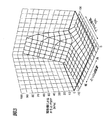
図3は、電動機による過給圧かさ上げ分を決定するためのマップである。
図4は、電動機のコントローラへの指示値を決定するためのマップである。FIG. 1 is a configuration diagram showing a configuration of an engine having an embodiment of a control device for an internal combustion engine with an electric supercharger according to the present invention.
FIG. 2 is a flowchart of supercharging pressure control.
FIG. 3 is a map for determining the boost pressure boosting amount by the electric motor.
FIG. 4 is a map for determining an instruction value to the controller of the electric motor.
本発明の電動過給機付内燃機関の制御装置の一実施形態について以下に説明する。本実施形態の電動過給機付内燃機関の制御装置を有するエンジン1を図1に示す。 An embodiment of a control device for an internal combustion engine with an electric supercharger according to the present invention will be described below. FIG. 1 shows an
本実施形態で説明するエンジン1は、車両に搭載された多気筒エンジンであるが、ここではそのうちの一気筒のみが断面図として図1に示されている。エンジン1は、インジェクタ2によってシリンダ3内のピストン4の上面に燃料を噴射するいわゆる筒内噴射型のエンジンである。このエンジン1は、均質燃焼だけでなく成層燃焼も可能である。また、このエンジン1は、希薄燃焼(リーンバーンエンジン)も可能であり、後述するターボチャージャ11によってより多くの吸入空気を過給してリーンバーンを行うことによって、高出力化だけでなく低燃費化をも実現し得るものである。 The
エンジン1は、吸気通路5を介してシリンダ3内に吸入した空気をピストン4によって圧縮し、ピストン4の上面に形成された窪みの内部に燃料を噴射して濃い混合気を点火プラグ7近傍に集め、これに点火プラグ7で着火させて燃焼させる。このときの燃焼によってシリンダ3内の圧力は上昇してピストン4が往復運動され、この往復運動がコネクティングロッドによって回転運動に変換されて出力として取り出される。出力された駆動力はトランスミッション(変速機)27によって減速又は増速されて(変速されて)駆動輪を回転させる。 The
シリンダ3の内部と吸気通路5との間は、吸気バルブ8によって開閉される。燃焼後の排気ガスは排気通路6に排気される。シリンダ3の内部と排気通路6との間は、排気バルブ9によって開閉される。吸気通路5上には、上流側からエアクリーナ10、ターボユニット(過給機)11、インタークーラー12、スロットルバルブ13などが配置されている。エアクリーナ10は、吸入空気中のゴミや塵などを取り除くフィルタである。ターボユニット11は、吸気通路5と排気通路6との間に配され、過給を行うものである。本実施形態のターボユニット11においては、タービン側インペラーとコンプレッサ側インペラーとが回転軸で連結されている(以下、この部分を単にタービン/コンプレッサ11aと言うこととする)。 An
また、本実施形態のターボチャージャは、タービン/コンプレッサ11aの回転軸が出力軸となるように電動機11bが組み込まれている電動機付ターボチャージャである。電動機11bは、交流モータであり、発電機としても機能し得る。ターボユニット11は、排気エネルギーによってのみ過給を行う通常の過給機としても機能し得るが、電動機11bによってタービン/コンプレッサ11aを強制的に駆動することでさらなる過給を行うこともできる。 In addition, the turbocharger of this embodiment is a turbocharger with an electric motor in which an
さらに、排気エネルギーを利用して、タービン/コンプレッサ11aを介して電動機11bを回転させることで回生発電させ、発電された電力を回収することもできる。図示されていないが、電動機11bは、タービン/コンプレッサ11aの回転軸に固定されたロータと、その周囲に配置されたステータとを主たる構成部分として有している。吸気通路5上のターボユニット11の下流側には、ターボユニット11による過給で圧力上昇に伴って温度が上昇した吸入空気の温度を下げる空冷式インタークーラ12が配されている。インタークーラー12によって吸入空気の温度を下げ、充填効率を向上させる。 Furthermore, by using the exhaust energy, the electric power can be regenerated by rotating the
インタークーラー12の下流側には、吸入空気量を調節するスロットルバルブ13が配されている。本実施形態のスロットルバルブ13は、いわゆる電子制御式スロットルバルブであり、アクセルペダル14の操作量をアクセルポジションセンサ15で検出し、この検出結果と他の情報量とに基づいてECU(制御手段)16がスロットルバルブ13の開度を決定するものである。スロットルバルブ13は、これに付随して配設されたスロットルモータ17によって開閉される。また、スロットルバルブ13に付随して、その開度を検出するスロットルポジショニングセンサ18も配設されている。 A throttle valve 13 that adjusts the amount of intake air is disposed downstream of the intercooler 12. The throttle valve 13 of the present embodiment is a so-called electronically controlled throttle valve, and an operation amount of the
スロットルバルブ13の下流側には、吸気通路5内の圧力(吸気圧)を検出する圧力センサ19が配設されている。これらのセンサ15,18,19はECU16に接続されており、その検出結果をECU16に送出している。ECU16は、CPU,ROM,RAM等からなる電子制御ユニットである。ECU16には、上述したインジェクタ2、点火プラグ7や、電動機11b、等が接続されており、これらはECU16からの信号によって制御されている。ECU16には、このほかにも、カムポジションを検出するカムポジションセンサ20や、電動機11bと接続されたコントローラ(制御手段)21・バッテリ22なども接続されている。コントローラ21は、電動機11bの駆動を制御するだけでなく、電動機11bが回生発電した電力の電圧変換を行うインバータとしての機能も有している。回生発電による電力は、コントローラ21によって電圧変換された後にバッテリ22に充電される。 A
一方、排気通路6上には、排気ガスを浄化する排気浄化触媒23がターボユニット11の下流側に取り付けられている。そして、排気通路6(ターボユニット11の上流部)から吸気通路5(圧力センサ19の設置されたサージタンク部)にかけて排気ガスを還流させるためのEGR(Exhaust GasRecirculation)通路24が配設されている。EGR通路24上には、排気ガス還流量を調節するEGRバルブ25が取り付けられている。EGRバルブ25の開度制御も上述したECU16によって行われる。 On the other hand, on the exhaust passage 6, an
また、エンジン1のクランクシャフト近傍には、エンジン回転数を検出する回転数センサ26が取り付けられている。なお、トランスミッション27は、内部のコントロールバルブ28がECU16からの信号を受けて駆動されることで変速動作を行う。即ち、トランスミッション27のギヤ位置は、ECU16によって把握されている。なお、図示したトランスミッション27はオートマチックトランスミッション(前進5速・後退1速)であるが、マニュアルトランスミッションであっても良い。マニュアルトランスミッションの場合は、そのギアポジションを検出するセンサが設けられる。 Further, a
上述した電動機11bを用いた過給圧制御の基本部分を説明する。図2に、本制御のフローチャートを示す。図2に示されるフローチャートの制御は、所定時間毎(例えば、32ms毎)に繰り返し実行されている。 The basic part of the supercharging pressure control using the above-described
まず、エンジン回転数が回転数センサ26によって検出されると共に、エンジン負荷が吸入空気量(圧力センサ19から推定)やスロットル開度(スロットルポジショニングセンサ18によって検出)から推定される(ステップ200)。次に、エンジン回転数とエンジン負荷とから、ベース目標過給圧Bが算出される(ステップ205)。ベース目標過給圧Bとは、定常運転時における所定エンジン回転数・所定エンジン負荷のときに発生すると予想される過給圧であり、予め実験などによって取得されてECU16内のROM内にマップとして格納されている。 First, the engine speed is detected by the
次に、回転数センサ26によって検出されたエンジン回転数とアクセルポジションセンサ15によって検出されるアクセル開度とに基づいて、電動機11bによってかさ上げする分の過給圧Pを決定する(ステップ210)。エンジン回転数とアクセル開度とかさ上げ分の過給圧Pとの関係は、予め実験などを通じて決定されており、マップとしてECU16内のROMに格納されている。このマップを図3に示す。図3に示されるように、ここでは、エンジン回転数が所定回転数以下で、かつ、アクセル開度が所定開度以上である領域が特定運転領域として設定されており、エンジン1の状態がこの特定運転領域内で運転されているときにのみ、上述したかさ上げ分の過給圧Pが正の値として設定され、電動機11bによるアシストが行われる。特定運転領域内でも、より低回転、より大きなアクセル開度となるほどかさ上げ過給圧Pが大きくなるようになされている。 Next, based on the engine rotational speed detected by the
エンジン1の状態が特定運転領域外の状態である場合には、上述したかさ上げ過給圧Pが0ではなく負の値として設定されることによって電動機11bによるアシストが実質的に禁止されている。かさ上げ過給圧Pを負の値として設定することの意味は追って説明する。ステップ210の後、トランスミッション27のギアポジションが検出され、このギアポジションに応じて補正係数Kが決定される。ここでは、以下の[表1]に基づいて補正係数Kが決定される(ステップ212)。 When the state of the

補正係数Kの決定後、目標過給圧T=補正係数K×(ベース目標過給圧B+かさ上げ分の過給圧P)として目標過給圧Tを算出する(ステップ215)。[表1]から明らかなように、目標過給圧Tは、補正係数Kによってギアポジションが低速段側である場合に(あるいは、低速段側であるほど)、高速段側である場合よりも高くなる。 After the correction coefficient K is determined, the target supercharging pressure T is calculated as target supercharging pressure T = correction coefficient K × (base target supercharging pressure B + supercharging pressure P for raising) (step 215). As is apparent from [Table 1], the target boost pressure T is determined by the correction coefficient K when the gear position is on the low speed stage side (or on the low speed stage side) than when the gear position is on the high speed stage side. Get higher.
なお、目標過給圧Tは、電動機11bによる過給制御のために設定される制御上の目標値であり、実際に欲しい過給圧と一致しない場合もある。例えば、図3のマップから分かるように、低回転でアクセル開度が大きいときには、かさ上げ分Pが大きく設定され、目標過給圧Tは大きく設定される。しかし、このときの目標過給圧Tは実際には達成し得ない過給圧となる場合もある。このように目標過給圧Tを設定することで、電動機11bによる過給圧のフルアシストが確実に継続して行われるようにすることもできる。特に、かさ上げ分Pが正に設定される場合、即ち、積極的に電動機11bによる過給を行うべきと思われる状況では、この目標過給圧Tは、かさ上げ分Pを介して、実際に欲しいと思われる過給圧よりもやや大きめに設定され、電動機11bによる過給が確実に行われるようにされる。 The target supercharging pressure T is a control target value set for supercharging control by the
目標過給圧Tの算出後、圧力センサ19によって吸気管内圧力を実過給圧Cとして検出し(ステップ220)、上述した目標過給圧Tと検出した実過給圧Cとの差ΔPを算出する(ステップ225)。次いで、算出された差ΔPが0より大きいか否かを判定し(ステップ230)、差ΔPが0以下であれば、電動機11bによるアシストの有無を示すアシストフラグFassistを0にして電動機11bによる過給アシストを行わずに図2のフローチャートを一旦抜ける。ここで、上述したかさ上げ過給分Pが正の値であっても、差ΔPが0以下であれば、電動機11bによる過給は行われない。一方、ステップ230が肯定される場合、即ち、差ΔPが0より大きい場合は、電動機11bによる過給アシストを行うための指示値を差ΔPに基づいて決定し、この指令値をコントローラ21に対して出力する(ステップ235)。 After calculating the target supercharging pressure T, the
差ΔPとコントローラ21に与える指令値との関係を図4に示す。図4の実線で示されるように、コントローラ21への指令値は電圧値によって行われる。差ΔPが大きいほど、大きな電圧値がコントローラ21に対して送出される。その電圧値の範囲は、ここでは0〜4.3Vの範囲である。4.3Vの電圧がコントローラ21に送出されると、コントローラ21は電動機11bをフル駆動させて過給をフルアシストする。コントローラ21への指示値の送出後、アシストフラグFassistが1にされ(ステップ240)、コントローラ21が受け取った指示値に基づいて電動機11bが制御される(ステップ245)。 The relationship between the difference ΔP and the command value given to the
上述したように、目標過給圧Tは、トランスミッション27のギアポジションが低速段側であるほど大きくなるようになされている。このため、トランスミッション27のギアポジションが低速段側である場合に(あるいは、低速段側であるほど)、(同一条件で高速段側である場合に比べて)差ΔPは大きくなる。この結果、電動機11bへの供給電圧が高くなり、電動機11bによる過給アシスト量が増加される。トランスミッション27が低速段側である場合に(あるいは、低速段側であるほど)電動機の過給アシスト効果が増強されるため、タービン/コンプレッサ11aの回転は急峻に立ち上げられる。トランスミッション27が低速段側である場合は、加速時のエンジン回転数の立ち上がりが急峻となるが、このようにタービン/コンプレッサ11aの回転も急峻に立ち上げられるため、過渡的な出力低下を防止することができる。 As described above, the target boost pressure T is increased as the gear position of the
上述したように、トランスミッション27のギアポジションが低速段側にある(車速が低い)場合は、追い越し加速(全開加速)等が行われると、エンジン回転数が最高回転数(ギヤシフトアップ時回転数)に達するまでの時間が比較的短くなる(高速段側に比べて短くなる)。本実施形態のようなギアポジションに応じた補正を行わないと、ターボ回転数の立ち上がりは、タービン/コンプレッサ11aの慣性モーメントの影響でエンジン回転数に対する応答遅れが大きくなってしまう。 As described above, when the gear position of the
なお、応答遅れが大きくなる要因としては、排気マニフォールドなどタービン上流側の排気系からの放熱に伴う排ガス温度低下も挙げられる。ターボユニット11のタービンを回転させる排気エネルギーは、排気ガス温度にも影響を受けるため、排ガス温度が低下すればタービンを回転させるエネルギーも低下してしまう。また、この応答遅れのために、エンジンの大幅なダウンサイジングが計れずに実用燃費の改善ができないという側面もある。 Note that a factor that increases the response delay includes a decrease in exhaust gas temperature accompanying heat radiation from the exhaust system upstream of the turbine, such as an exhaust manifold. Exhaust energy for rotating the turbine of the
本実施形態では、ギアポジションに応じた補正を行うことで上述した応答遅れを解消し、低速域での車両加速性能の過渡的な低下を抑止している。また、大幅なダウンサイジングによる実用燃費の改善も可能となる。なお、高速走行(ギアポジションが高速段側)での加速の場合は、走行抵抗も大きく、エンジン回転数の上昇速度も小さくなる結果、排気系そのものの温度上昇も高い(定常全負荷に近づく)。このため、高速域(ギアポジションが高速段側)となるほどターボ回転数の応答遅れは小さくなる。 In the present embodiment, the response delay described above is eliminated by performing correction according to the gear position, and a transient decrease in vehicle acceleration performance in a low speed region is suppressed. In addition, it is possible to improve practical fuel consumption by drastic downsizing. When accelerating at high speed (the gear position is at the high speed side), the resistance of the engine is high and the speed of increase of the engine speed is low. As a result, the temperature of the exhaust system itself is high (close to the steady full load). . For this reason, the response delay of the turbo rotational speed becomes smaller as the speed is higher (the gear position is higher speed side).
また、上述した補正係数Kに対して制限を設けることも可能である。例えば、車両がトラクションコントロール制御を併用しているような場合に、車輪のスリップを検出したときに補正係数の大きさを小さくする制限を加えてもよい。車輪がスリップしている場合は、エンジンの出力を絞って車輪のスリップを抑止する。このため、車輪のスリップが検出された場合は、補正係数Kによって目標過給圧T(過給アシスト量)が増強されるのを抑止する。この場合、補正係数Kの利用を禁止しても良いし、補正係数Kの値をステップ212で決定されたものの80%にするなどの手法がある。あるいは、補正係数K以外の補正係数を用いても良い。 It is also possible to place a limit on the correction coefficient K described above. For example, when the vehicle is also using traction control control, a restriction may be added to reduce the magnitude of the correction coefficient when wheel slip is detected. If the wheel is slipping, the engine output is throttled to prevent the wheel from slipping. Therefore, when wheel slip is detected, the target supercharging pressure T (supercharging assist amount) is prevented from being increased by the correction coefficient K. In this case, use of the correction coefficient K may be prohibited, and there are methods such as setting the value of the correction coefficient K to 80% of that determined in step 212. Alternatively, a correction coefficient other than the correction coefficient K may be used.
また、ここでは、上述した特定運転領域外のときはかさ上げ過給分Pを負の値として設定している。このようにすることで、算出される目標過給圧Tがより少なく算出されることとなり、その結果、差ΔPもより小さく算出されることになる。電動機11bによる過給圧制御を行うか否かは、差ΔPの大きさに基づいて判定するので、差ΔPがより小さく算出されるということは、電動機11bによる過給圧制御が行われにくくなるということになる。差ΔPは、小さめに算出される目標過給圧Tと実過給圧Cとの差であるので、電動機11bによる過給圧制御の要否を判定する上で、結果的に実過給圧Cに対してある程度の変動幅を確保することになる。 Here, when the vehicle is outside the above-described specific operation region, the supercharging amount P is set as a negative value. By doing so, the calculated target boost pressure T is calculated to be smaller, and as a result, the difference ΔP is also calculated to be smaller. Whether or not the supercharging pressure control by the
このようにすると、外乱などに起因して実過給圧Cが変動しただけのような、電動機11bによるアシストを始めたくないような場合に電動機11bによる過給圧が行われにくくなり、過給圧制御を安定して行うことができる。例えば、外乱などで実過給圧Cが微小な増減を繰り返して変動するような場合に電動機11bによる過給の開始停止が頻繁に繰り返されてしまうと過給圧制御がかえって荒れてしまう。即ち、電動機11bによる不要な過給圧制御が行われてしまう。そこで、電動機11bによる過給が必要ないと思われるとき(特定運転領域外のとき)は、電動機11bによる過給が開始されにくいようにしておくことによって過給圧制御の安定化を図っている。なお、上述した実施形態は、「変速機のギアポジションが低い場合に、高い場合に比べて、前記電動機による過給アシスト量を増加させる」実施形態であると共に、「変速機のギアポジションが低いほど、高い場合に比べて、前記電動機による過給アシスト量を増加させる」実施形態である。 In this way, when it is not desired to start assisting by the
なお、本発明は上述した実施形態に限定されるものではない。上述した実施形態では、本発明の電動過給機付内燃機関の制御装置を直噴ガソリンエンジンに適用したが、直噴でないガソリンエンジンやディーゼルエンジンなどに適用することも可能である。また、上述した実施形態では、過給機がターボチャージャであったが、ターボチャージャではなく、例えば、電動機付ターボチャージャの排気側を除いたような、電動式のコンップレッサなどであっても良い。さらに、上述した実施形態では、目標過給圧T=補正係数K×(ベース目標過給圧B+かさ上げ分の過給圧P)として目標過給圧Tを算出したが、目標過給圧T=ベース目標過給圧B+(かさ上げ分の過給圧P×補正係数K)として目標過給圧Tを算出しても良い。 In addition, this invention is not limited to embodiment mentioned above. In the embodiment described above, the control device for an internal combustion engine with an electric supercharger according to the present invention is applied to a direct-injection gasoline engine, but it can also be applied to a gasoline engine or a diesel engine that is not direct-injection. In the above-described embodiment, the turbocharger is a turbocharger. However, instead of the turbocharger, for example, an electric compressor such as an exhaust side of a turbocharger with an electric motor may be used. Furthermore, in the above-described embodiment, the target boost pressure T is calculated as the target boost pressure T = correction coefficient K × (base target boost pressure B + supercharging pressure P for raising), but the target boost pressure T The target supercharging pressure T may be calculated as: base target supercharging pressure B + (supercharging pressure P for raising) × correction coefficient K).
本発明に記載の電動過給機付内燃機関の制御装置によれば、変速機が低速段にある場合に(あるいは、低速段側にあるほど)、高い場合に比べて、過給アシスト量が増加されるため、低速域での車両加速性能の過渡的な低下を抑止でき、全てのギヤポジション(即ち、全ての車速域)において好適な過給効果を得ることができる。 According to the control device for an internal combustion engine with an electric supercharger according to the present invention, when the transmission is in the low speed stage (or as it is closer to the low speed stage), the supercharging assist amount is higher than when the transmission is high. Therefore, a transient decrease in the vehicle acceleration performance in the low speed range can be suppressed, and a suitable supercharging effect can be obtained in all gear positions (that is, all vehicle speed ranges).
Claims (7)
前記内燃機関の過給を行う電動機付過給機と、
前記電動機による過給を制御する制御手段と、
前記内燃機関の出力を変速する変速機とを備えており、
前記制御手段が、前記変速機のギアポジションが低い場合に、高い場合に比べて、前記電動機による過給アシスト量を増加させることを特徴とする電動過給機付内燃機関の制御装置。An internal combustion engine mounted on the vehicle;
A supercharger with an electric motor for supercharging the internal combustion engine;
Control means for controlling supercharging by the electric motor;
A transmission for shifting the output of the internal combustion engine,
The control device for an internal combustion engine with an electric supercharger, wherein the control means increases the supercharging assist amount by the electric motor when the gear position of the transmission is low compared to when the gear position is high.
前記内燃機関の過給を行う電動機付過給機と、
前記電動機による過給を制御する制御手段と、
前記内燃機関の出力を変速する変速機とを備えており、
前記制御手段が、前記変速機のギアポジションが低いほど、高い場合に比べて、前記電動機による過給アシスト量を増加させることを特徴とする電動過給機付内燃機関の制御装置。An internal combustion engine mounted on the vehicle;
A supercharger with an electric motor for supercharging the internal combustion engine;
Control means for controlling supercharging by the electric motor;
A transmission for shifting the output of the internal combustion engine,
The control device for an internal combustion engine with an electric supercharger, wherein the control means increases the supercharging assist amount by the electric motor as the gear position of the transmission is lower than when the gear position is higher.
Applications Claiming Priority (3)
| Application Number | Priority Date | Filing Date | Title |
|---|---|---|---|
| JP2004064609 | 2004-03-08 | ||
| JP2004064609 | 2004-03-08 | ||
| PCT/JP2005/004017 WO2005085612A1 (en) | 2004-03-08 | 2005-03-02 | Control device for internal combustion engine with electrically driven supercharger |
Publications (2)
| Publication Number | Publication Date |
|---|---|
| JP4380701B2 true JP4380701B2 (en) | 2009-12-09 |
| JPWO2005085612A1 JPWO2005085612A1 (en) | 2010-02-04 |
Family
ID=34918196
Family Applications (1)
| Application Number | Title | Priority Date | Filing Date |
|---|---|---|---|
| JP2006510789A Active JP4380701B2 (en) | 2004-03-08 | 2005-03-02 | Control device for internal combustion engine with electric supercharger |
Country Status (4)
| Country | Link |
|---|---|
| JP (1) | JP4380701B2 (en) |
| CN (1) | CN1930386B (en) |
| DE (1) | DE112005000534B4 (en) |
| WO (1) | WO2005085612A1 (en) |
Families Citing this family (10)
| Publication number | Priority date | Publication date | Assignee | Title |
|---|---|---|---|---|
| JP5197528B2 (en) * | 2008-12-25 | 2013-05-15 | 本田技研工業株式会社 | Engine load detection device and engine load detection method |
| JP5703684B2 (en) * | 2010-10-26 | 2015-04-22 | いすゞ自動車株式会社 | Engine supercharger |
| US8915082B2 (en) * | 2011-02-03 | 2014-12-23 | Ford Global Technologies, Llc | Regenerative assisted turbocharger system |
| US9303554B2 (en) | 2011-04-08 | 2016-04-05 | Ihi Corporation | Power-assisted supercharger and method for controlling same |
| KR101326972B1 (en) * | 2011-12-07 | 2013-11-13 | 현대자동차주식회사 | System of miller cycle engine and control method |
| JP6115580B2 (en) * | 2015-02-20 | 2017-04-19 | トヨタ自動車株式会社 | Control device for internal combustion engine |
| DE102015219337A1 (en) * | 2015-10-07 | 2017-04-13 | Robert Bosch Gmbh | Method and device for operating a drive device, drive device |
| CN107435585B (en) * | 2016-05-27 | 2020-03-31 | 长城汽车股份有限公司 | Vehicle control method and system and vehicle |
| CN108757154A (en) * | 2018-05-25 | 2018-11-06 | 上海永耐商贸有限公司 | Dynamoelectric compressor and turbocharger tandem pressure charging system |
| JP7151618B2 (en) * | 2019-05-14 | 2022-10-12 | トヨタ自動車株式会社 | vehicle |
Family Cites Families (10)
| Publication number | Priority date | Publication date | Assignee | Title |
|---|---|---|---|---|
| JPH0610416B2 (en) * | 1987-12-28 | 1994-02-09 | いすゞ自動車株式会社 | Controller for turbocharger with rotating electric machine |
| JPH0715263B2 (en) * | 1988-10-31 | 1995-02-22 | いすゞ自動車株式会社 | Turbocharger controller |
| JPH06272565A (en) * | 1993-03-22 | 1994-09-27 | Toyota Motor Corp | Control device of engine with turbo charger |
| JPH07247852A (en) * | 1994-03-11 | 1995-09-26 | Isuzu Motors Ltd | Acceleration control device for tcg |
| US6256993B1 (en) * | 1995-07-28 | 2001-07-10 | Honeywell International, Inc. | Motor-assisted variable geometry turbocharging system |
| US5870894A (en) * | 1996-07-16 | 1999-02-16 | Turbodyne Systems, Inc. | Motor-assisted supercharging devices for internal combustion engines |
| JPH10159574A (en) * | 1996-11-29 | 1998-06-16 | Aisin Seiki Co Ltd | Control device for turbocharger with dynamo-electric machine |
| US6205786B1 (en) * | 1999-06-16 | 2001-03-27 | Caterpillar Inc. | Engine having increased boost at low engine speeds |
| JP3912131B2 (en) * | 2002-02-18 | 2007-05-09 | トヨタ自動車株式会社 | Supercharging pressure control device |
| JP4337092B2 (en) * | 2003-12-26 | 2009-09-30 | 株式会社デンソー | Supercharger control device for internal combustion engine |
-
2005
- 2005-03-02 CN CN200580007449XA patent/CN1930386B/en not_active Expired - Fee Related
- 2005-03-02 DE DE112005000534T patent/DE112005000534B4/en not_active Expired - Fee Related
- 2005-03-02 JP JP2006510789A patent/JP4380701B2/en active Active
- 2005-03-02 WO PCT/JP2005/004017 patent/WO2005085612A1/en active Application Filing
Also Published As
| Publication number | Publication date |
|---|---|
| DE112005000534B4 (en) | 2011-06-09 |
| DE112005000534T5 (en) | 2007-01-18 |
| JPWO2005085612A1 (en) | 2010-02-04 |
| CN1930386A (en) | 2007-03-14 |
| WO2005085612A1 (en) | 2005-09-15 |
| CN1930386B (en) | 2011-12-28 |
Similar Documents
| Publication | Publication Date | Title |
|---|---|---|
| JP4380701B2 (en) | Control device for internal combustion engine with electric supercharger | |
| JP4380674B2 (en) | Supercharging pressure control device | |
| JP3925397B2 (en) | Turbocharger control device with electric motor | |
| US20120111305A1 (en) | Methods and Systems for Engine Control | |
| JP4289194B2 (en) | Multi-cylinder internal combustion engine supercharger | |
| JP2010249019A (en) | Internal combustion engine | |
| JP6661593B2 (en) | Control device for internal combustion engine | |
| JP3912131B2 (en) | Supercharging pressure control device | |
| JP4048828B2 (en) | Control device for internal combustion engine | |
| JP4023421B2 (en) | Control device for internal combustion engine | |
| JP2006322398A (en) | Internal combustion engine | |
| JP4013816B2 (en) | Control device for supercharger with electric motor | |
| JP2006238700A (en) | Vehicle control unit | |
| JP2007278066A (en) | Control device for internal combustion engine | |
| JP2003322038A (en) | Internal-combustion engine control device | |
| JP2004197653A (en) | Vehicle control device | |
| JP4013893B2 (en) | Control device for internal combustion engine having supercharger with electric motor | |
| JP2008045406A (en) | Egr control device | |
| JP4075596B2 (en) | Control device for internal combustion engine | |
| JP2005291019A (en) | Supercharging device for multicylinder internal combustion cylinder | |
| US20230358187A1 (en) | Vehicle control method and vehicle control device | |
| JP4019792B2 (en) | Vehicle control device | |
| JP4858237B2 (en) | Control device for internal combustion engine | |
| JP2004169673A (en) | Control device of internal combustion engine | |
| JP5334695B2 (en) | Electric supercharger control device |
Legal Events
| Date | Code | Title | Description |
|---|---|---|---|
| TRDD | Decision of grant or rejection written | ||
| A01 | Written decision to grant a patent or to grant a registration (utility model) |
Free format text: JAPANESE INTERMEDIATE CODE: A01 Effective date: 20090901 |
|
| A01 | Written decision to grant a patent or to grant a registration (utility model) |
Free format text: JAPANESE INTERMEDIATE CODE: A01 |
|
| A61 | First payment of annual fees (during grant procedure) |
Free format text: JAPANESE INTERMEDIATE CODE: A61 Effective date: 20090914 |
|
| FPAY | Renewal fee payment (event date is renewal date of database) |
Free format text: PAYMENT UNTIL: 20121002 Year of fee payment: 3 |
|
| R151 | Written notification of patent or utility model registration |
Ref document number: 4380701 Country of ref document: JP Free format text: JAPANESE INTERMEDIATE CODE: R151 |
|
| FPAY | Renewal fee payment (event date is renewal date of database) |
Free format text: PAYMENT UNTIL: 20121002 Year of fee payment: 3 |
|
| FPAY | Renewal fee payment (event date is renewal date of database) |
Free format text: PAYMENT UNTIL: 20131002 Year of fee payment: 4 |