JP4577260B2 - Engine starter - Google Patents
Engine starter Download PDFInfo
- Publication number
- JP4577260B2 JP4577260B2 JP2006118703A JP2006118703A JP4577260B2 JP 4577260 B2 JP4577260 B2 JP 4577260B2 JP 2006118703 A JP2006118703 A JP 2006118703A JP 2006118703 A JP2006118703 A JP 2006118703A JP 4577260 B2 JP4577260 B2 JP 4577260B2
- Authority
- JP
- Japan
- Prior art keywords
- engine
- internal pressure
- cylinder internal
- fluctuation component
- motor
- Prior art date
- Legal status (The legal status is an assumption and is not a legal conclusion. Google has not performed a legal analysis and makes no representation as to the accuracy of the status listed.)
- Expired - Fee Related
Links
Images


Classifications
-
- B—PERFORMING OPERATIONS; TRANSPORTING
- B60—VEHICLES IN GENERAL
- B60K—ARRANGEMENT OR MOUNTING OF PROPULSION UNITS OR OF TRANSMISSIONS IN VEHICLES; ARRANGEMENT OR MOUNTING OF PLURAL DIVERSE PRIME-MOVERS IN VEHICLES; AUXILIARY DRIVES FOR VEHICLES; INSTRUMENTATION OR DASHBOARDS FOR VEHICLES; ARRANGEMENTS IN CONNECTION WITH COOLING, AIR INTAKE, GAS EXHAUST OR FUEL SUPPLY OF PROPULSION UNITS IN VEHICLES
- B60K6/00—Arrangement or mounting of plural diverse prime-movers for mutual or common propulsion, e.g. hybrid propulsion systems comprising electric motors and internal combustion engines ; Control systems therefor, i.e. systems controlling two or more prime movers, or controlling one of these prime movers and any of the transmission, drive or drive units Informative references: mechanical gearings with secondary electric drive F16H3/72; arrangements for handling mechanical energy structurally associated with the dynamo-electric machine H02K7/00; machines comprising structurally interrelated motor and generator parts H02K51/00; dynamo-electric machines not otherwise provided for in H02K see H02K99/00
- B60K6/20—Arrangement or mounting of plural diverse prime-movers for mutual or common propulsion, e.g. hybrid propulsion systems comprising electric motors and internal combustion engines ; Control systems therefor, i.e. systems controlling two or more prime movers, or controlling one of these prime movers and any of the transmission, drive or drive units Informative references: mechanical gearings with secondary electric drive F16H3/72; arrangements for handling mechanical energy structurally associated with the dynamo-electric machine H02K7/00; machines comprising structurally interrelated motor and generator parts H02K51/00; dynamo-electric machines not otherwise provided for in H02K see H02K99/00 the prime-movers consisting of electric motors and internal combustion engines, e.g. HEVs
- B60K6/42—Arrangement or mounting of plural diverse prime-movers for mutual or common propulsion, e.g. hybrid propulsion systems comprising electric motors and internal combustion engines ; Control systems therefor, i.e. systems controlling two or more prime movers, or controlling one of these prime movers and any of the transmission, drive or drive units Informative references: mechanical gearings with secondary electric drive F16H3/72; arrangements for handling mechanical energy structurally associated with the dynamo-electric machine H02K7/00; machines comprising structurally interrelated motor and generator parts H02K51/00; dynamo-electric machines not otherwise provided for in H02K see H02K99/00 the prime-movers consisting of electric motors and internal combustion engines, e.g. HEVs characterised by the architecture of the hybrid electric vehicle
- B60K6/48—Parallel type
-
- B—PERFORMING OPERATIONS; TRANSPORTING
- B60—VEHICLES IN GENERAL
- B60W—CONJOINT CONTROL OF VEHICLE SUB-UNITS OF DIFFERENT TYPE OR DIFFERENT FUNCTION; CONTROL SYSTEMS SPECIALLY ADAPTED FOR HYBRID VEHICLES; ROAD VEHICLE DRIVE CONTROL SYSTEMS FOR PURPOSES NOT RELATED TO THE CONTROL OF A PARTICULAR SUB-UNIT
- B60W2555/00—Input parameters relating to exterior conditions, not covered by groups B60W2552/00, B60W2554/00
- B60W2555/20—Ambient conditions, e.g. wind or rain
-
- Y—GENERAL TAGGING OF NEW TECHNOLOGICAL DEVELOPMENTS; GENERAL TAGGING OF CROSS-SECTIONAL TECHNOLOGIES SPANNING OVER SEVERAL SECTIONS OF THE IPC; TECHNICAL SUBJECTS COVERED BY FORMER USPC CROSS-REFERENCE ART COLLECTIONS [XRACs] AND DIGESTS
- Y02—TECHNOLOGIES OR APPLICATIONS FOR MITIGATION OR ADAPTATION AGAINST CLIMATE CHANGE
- Y02T—CLIMATE CHANGE MITIGATION TECHNOLOGIES RELATED TO TRANSPORTATION
- Y02T10/00—Road transport of goods or passengers
- Y02T10/60—Other road transportation technologies with climate change mitigation effect
- Y02T10/62—Hybrid vehicles
Landscapes
- Engineering & Computer Science (AREA)
- Chemical & Material Sciences (AREA)
- Combustion & Propulsion (AREA)
- Transportation (AREA)
- Mechanical Engineering (AREA)
- Hybrid Electric Vehicles (AREA)
- Output Control And Ontrol Of Special Type Engine (AREA)
- Control Of Vehicle Engines Or Engines For Specific Uses (AREA)
- Combined Controls Of Internal Combustion Engines (AREA)
- Electric Propulsion And Braking For Vehicles (AREA)
Description
本発明は、車両用エンジン、特に、モータとエンジンを原動機とするハイブリッド車、あるいは、信号待ちなどでエンジンを停止した後、スタータモータでエンジンを再始動して発進するアイドルストップ車などでエンジンを始動(クランキング)する際に発生する振動を抑制する技術に関する。 The present invention is applied to a vehicle engine, in particular, a hybrid vehicle using a motor and an engine as a prime mover, or an idle stop vehicle that starts after restarting the engine with a starter motor after stopping the engine by waiting for a signal or the like. The present invention relates to a technique for suppressing vibrations that occur when starting (cranking).
特許文献1には、ハイブリッド車において、始動後所期の機関回転数に達するまでの回転数域ではトルク制御を行い、以後は回転数制御を行う一方、トルク制御は、始動後経過時間に応じて定まる基本トルク値に、機関クランク角に応じて定まる回転振動抑制トルクを加えて生成したトルク指令値に基づいて行うようにした技術が開示されている。
特許文献1では、モータによってエンジンをクランキングする際のトルク変動が大きなエンジンでは、回転振動抑制トルクが大きくなり、モータサイズを考えると基本トルクを大きくすることができないため、回転振動を十分抑制することができない。
また、デコンプその他のシリンダ内圧を変更する手段を備えたエンジンでは、デコンプ量等に応じたシリンダ内圧によって、エンジントルクの変動量が変わるので、クランク角に応じて振動抑制トルクを定めるだけでは、過不足が生じる.
In
Also, in an engine equipped with a decompression or other means for changing the cylinder internal pressure, the amount of fluctuation in the engine torque varies depending on the cylinder internal pressure corresponding to the decompression amount, etc. A shortage occurs.
上記の課題を解決するため、本発明は、モータによるエンジンの始動時、モータの出力トルクにエンジンのクランク角に応じた変動成分を印加し振動抑制を行うエンジンの始動装置において、エンジンのシリンダ内圧を検出するシリンダ内圧検出手段と、前記検出したシリンダ内圧に応じて前記モータトルクに印加する変動成分の大きさを調節する変動成分調節手段と、エンジンのシリンダ内圧を変更するシリンダ内圧変更手段と、を含み、
前記シリンダ内圧変更手段は、吸気弁の開閉時期,作動角の少なくとも一方を変更する可変動弁機構を含んで構成され、前記変動成分調節手段は、前記吸気弁の開閉時期,作動角の少なくとも一方に応じて前記変動成分の大きさを調節することを特徴とする。
In order to solve the above-mentioned problems, the present invention provides an engine starter that suppresses vibration by applying a fluctuation component corresponding to the crank angle of the engine to the output torque of the motor when the engine is started by the motor. A cylinder internal pressure detecting means for detecting, a fluctuation component adjusting means for adjusting the magnitude of the fluctuation component applied to the motor torque in accordance with the detected cylinder internal pressure, a cylinder internal pressure changing means for changing the cylinder internal pressure of the engine, Including
The cylinder internal pressure changing means includes a variable valve mechanism that changes at least one of the opening / closing timing and operating angle of the intake valve, and the fluctuation component adjusting means is at least one of the opening / closing timing and operating angle of the intake valve. The size of the fluctuation component is adjusted according to the above .
かかる構成とすれば、シリンダ内圧(圧縮圧力)の大きさに応じて回転振動レベルが異なっても、シリンダ内圧に応じてモータトルクに印加する変動成分の大きさを調節することにより、回転振動を十分良好に抑制することができる。 With this configuration, even if the rotational vibration level differs depending on the magnitude of the cylinder internal pressure (compression pressure), the rotational vibration can be reduced by adjusting the magnitude of the fluctuation component applied to the motor torque according to the cylinder internal pressure. It can be suppressed sufficiently satisfactorily.
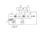
図1は、本発明が適用されるハイブリッド車用のパワートレインの一例を示す。
エンジン1の出力軸が、第1のクラッチ2を介してモータ・ジェネレータ3に連結され、モータ・ジェネレータ3の出力軸が第2のクラッチ4を介してトランスミッション5に連結されている。
エンジン1は、エンジンコントローラ(ECM)6、モータ・ジェネレータ3は、モータコントローラ(MC)7らの指令を受けてそれぞれ制御され、ECM6、MC7は、ハイブリッドコントローラ(HCM)8からの指令によって統合的に制御される。
FIG. 1 shows an example of a power train for a hybrid vehicle to which the present invention is applied.
An output shaft of the
The
バッテリ9は、前記各コントローラ6〜8に電力を供給する。
また、インバータ10は、バッテリ9からの直流電力を交流電力に変換してモータ・ジェネレータ3に出力し、モータ・ジェネレータ3をモータとして駆動すると共に、モータ・ジェネレータ3がジェネレータとして機能するときには、モータ・ジェネレータ3からの発電電力を直流電力に変換してバッテリ9を充電する。
The
The
モータ・ジェネレータ3は、走行駆動用とエンジン1の始動用との機能を兼ね備え、走行時には、第2のクラッチ4を接続し、エンジン1の駆動力を用いる(単独またはモータ・ジェネレータ3の駆動力との併用で)際には、第1のクラッチ2も接続する。また、エンジン1を始動する際には、第2のクラッチ4を切り離し、第1のクラッチ2を接続してクランキングを行う。
The motor /
そして、前記エンジン1には、後述するようにシリンダ内圧を変更する吸気弁開閉時期を可変する可変動弁機構、デコンプその他のシリンダ内圧変更手段11が装着されている。
図2は、パワートレインの別の例を示す。
図1と相違するのは、走行用の第1のモータ・ジェネレータ3とは別に、ベルト12を介してエンジン1と連動するエンジン始動用の第2のモータ・ジェネレータ13を備え、さらに該第2のモータ・ジェネレータ13とバッテリ9との間の第2のインバータ14、第2のモータ・ジェネレータ13に指令を与える第2のモータコントローラ15を備え、前記第2のクラッチ4が省略される点である。
The
FIG. 2 shows another example of a powertrain.
1 is different from the first motor /
図3は、前記HCM8の入出力状態を示す。
イグニッションキースイッチ信号IGNSW、ブレーキスイッチ信号BRSW、回転速度,クランク角信号CA、アクセル開度信号APS、車速信号VSP、バッテリ充電状態信号SOC、大気圧信号PA、吸入空気温度信号TA、エンジン冷却水温度信号TW、触媒温度信号TCを入力し、ECM6にエンジン目標トルク、始動許可信号を出力し、MC7にモータ・ジェネレータへのトルク制御/回転数制御との制御切換信号、モータ目標トルク信号、目標回転速度信号、エンジン目標トルク信号を出力し、シリンダ内圧変更手段11に動作制御信号を出力し、各クラッチ2、4にクラッチ制御信号を出力する。
FIG. 3 shows the input / output state of the
Ignition key switch signal IGNSW, brake switch signal BRSW, rotation speed, crank angle signal CA, accelerator opening signal APS, vehicle speed signal VSP, battery charge state signal SOC, atmospheric pressure signal PA, intake air temperature signal TA, engine coolant temperature Signal TW and catalyst temperature signal TC are input, engine target torque and start permission signal are output to ECM6, control switching signal between motor / generator torque control / rotational speed control, motor target torque signal, target rotation A speed signal and an engine target torque signal are output, an operation control signal is output to the cylinder internal
図4は、エンジン1の一例を示す。
エンジン1は、ディーゼルエンジンであり、吸入空気は、エアクリーナ22から吸気通路23、コレクタ24、吸気マニホールド25、吸気カム26により開閉駆動される吸気弁27を介してシリンダ28内に吸入される。
シリンダ28内には、ピストン29が嵌挿され、燃料噴射弁30によって燃料が噴射供給される。燃焼排気は、排気カム31によって開閉駆動される排気弁32を介して排気通路33へ排出される。
FIG. 4 shows an example of the
The
A
排気の一部は、EGRガスとしてEGR通路34に導入され、EGR弁35によってEGR量を制御されつつ吸気マニホールド25に還流される。
そして、シリンダ内圧変更手段として、下記の各手段のうち、少なくとも1つを備える。
スロットル弁36は、例えばバタフライ弁で構成され、吸気通路23の断面積を縮小して弁下流の圧力を低下させる{図6(A)参照}。
A part of the exhaust is introduced into the
And as a cylinder internal pressure change means, at least 1 is provided among the following each means.
The
吸気遮断弁37は、バタフライ弁、フラップ弁、ポペット弁などで構成され、連続的あるいは1サイクル中の所定区間に吸気通路を遮断し、弁下流の圧力を低下させる{図6(B)参照}。
吸気弁開閉時期可変手段及び吸気弁作動角可変手段38は、吸気カムの位相を変化させてバルブ中心角を変化させるものや、異なるプロフィールを持つ複数のカムの使用を切り換えるもの等、その他公知である可変動弁機構を用いて、吸気行程においてシリンダ内に流入する空気量を変更する{図6(C)参照}。連続可変式のものはシリンダ内圧変更時の段差が無く、切り換え式のものは速やかにシリンダ内圧を変更できるという利点がある。
The intake shut-off
The intake valve opening / closing timing varying means and the intake valve operating
図5は、シリンダ内圧変更手段としてデコンプ装置39を備えたエンジン1の例を示す。
デコンプ装置39は、吸・排気弁と別に設けた弁や、吸気弁または排気弁を圧縮行程においても微小量開くことで、圧縮行程においてもシリンダ内の空気を吸気或いは排気に逃がすもので構成される。
FIG. 5 shows an example of the
The
この他、図示しないが、圧縮比を可変な機構を備えたエンジンにおいては、圧縮比の変更によってシリンダ内圧(圧縮圧力)が変化するので、圧縮比可変機構がシリンダ内圧変更手段を構成し、圧縮比の増大をシリンダ内圧の増大として検出すればよい。
図7は、上記した少なくとも1つのシリンダ内圧変更手段で、エンジン始動(クランキング)時のシリンダ内圧を変更する実施形態の、回転振動抑制制御のフローを示す。
In addition, although not shown, in an engine having a mechanism with a variable compression ratio, the cylinder internal pressure (compression pressure) changes due to the change of the compression ratio. Therefore, the variable compression ratio mechanism constitutes the cylinder internal pressure changing means, and the compression is performed. An increase in the ratio may be detected as an increase in the cylinder internal pressure.
FIG. 7 shows a flow of rotational vibration suppression control in an embodiment in which the cylinder internal pressure at the time of engine start (cranking) is changed by at least one cylinder internal pressure changing means described above.
ステップS101では、エンジン回転速度NEおよびクランク角CAを読み込む。
ステップS102では、エンジン回転速度NEが所定値NE0以下かを判定し、NE0以下の場合はステップS103以降へ進んで、本発明に係るモータのトルク制御(目標トルクを設定して制御)によるクランキングを行い、NE0を超えたときは、ステップS108へ進んでモータの回転速度制御(目標回転速度を設定して制御)によるクランキングに切り換える。
In step S101, the engine speed NE and the crank angle CA are read.
In step S102, it is determined whether or not the engine speed NE is equal to or less than a predetermined value NE0. If NE0 or less, the process proceeds to step S103 and subsequent steps, and cranking by torque control (control by setting a target torque) according to the present invention is performed. If NE0 is exceeded, the process proceeds to step S108 to switch to cranking by motor rotation speed control (control by setting a target rotation speed).
ステップS103では、予め定めたマップの参照等により、クランク角CAに基づいて、回転振動抑制トルク基本値を読み込む{図8(a)参照}。ここで、回転振動抑制トルクは、エンジンの圧縮反力や動弁系負荷、図示しないがエンジン回転に同期して駆動される燃料ポンプの負荷等によって発生する脈動的なトルクを相殺するためのものである。
ステップS104では、シリンダ内圧変更手段の制御目標値を読み込む。
In step S103, the rotational vibration suppression torque basic value is read based on the crank angle CA by referring to a predetermined map {see FIG. 8 (a)}. Here, the rotational vibration suppression torque is used to cancel out the pulsating torque generated by the compression reaction force of the engine, the valve operating system load, the load of the fuel pump that is driven in synchronization with the engine rotation (not shown), etc. It is.
In step S104, the control target value of the cylinder internal pressure changing means is read.
ステップS105では、前記制御目標値に基づいてシリンダ内圧の推定値を算出する。なお、この算出機能が、シリンダ内圧検出手段を構成する。
ステップS106では、前記シリンダ内圧の推定値に応じて回転振動抑制制御ゲインを算出する{図8(b)参照}。
ステップS107では、前記回転振動抑制トルク基本値に、前記回転振動抑制制御ゲインを乗じて回転振動抑制トルクを算出する{図8(c)参照}。
In step S105, an estimated value of the cylinder internal pressure is calculated based on the control target value. This calculation function constitutes cylinder internal pressure detection means.
In step S106, a rotational vibration suppression control gain is calculated according to the estimated value of the cylinder internal pressure {see FIG. 8B}.
In step S107, the rotational vibration suppression torque is calculated by multiplying the rotational vibration suppression torque basic value by the rotational vibration suppression control gain {see FIG. 8 (c)}.
上記のように、回転振動抑制トルクを、エンジンのクランク角に応じて予め定めたマップにより求めた基本量に、シリンダ内圧に応じて求めるゲインを乗じて求める構成とすることで、簡単な計算で求めることができる。
ステップS109では、クランキングによるエンジン回転の上昇に必要なモータの基本トルクに、前記回転振動抑制トルクを重畳して最終的にモータに出力されるモータトルク制御値を算出する。
As described above, the rotational vibration suppression torque can be calculated by multiplying the basic amount obtained from the map determined in advance according to the crank angle of the engine by the gain obtained in accordance with the cylinder internal pressure. Can be sought.
In step S109, a motor torque control value that is finally output to the motor is calculated by superimposing the rotational vibration suppression torque on the basic torque of the motor necessary for increasing the engine rotation due to cranking.
図9は、同上の回転振動抑制制御を行ったときの各状態量の変化を示す。
モータトルクを増大させてクランキングを開始すると同時に、シリンダ内圧変更手段の動作量を増加させてシリンダ内圧を低下させ、この状態でエンジン回転速度NEが、エンジンマウンティングあるいはエンジン駆動系の共振域に入ってくるので、基本トルクに回転振動抑制トルクが重畳される。
FIG. 9 shows changes in the respective state quantities when the above-described rotational vibration suppression control is performed.
At the same time as cranking is started by increasing the motor torque, the operating amount of the cylinder internal pressure changing means is increased to decrease the cylinder internal pressure. In this state, the engine rotational speed NE enters the resonance range of the engine mounting or engine drive system. Therefore, the rotational vibration suppression torque is superimposed on the basic torque.
このように、エンジンマウントや駆動系の共振点を含む比較的回転速度の低い領域では、シリンダ内圧を下げてエンジントルク変動そのものを低下させる。これにより、回転振動抑制制御量が少なくて済み、消費電力を低減できる。また制御に誤差が生じた場合でも振動を比較的低く抑えることが可能である。
ディーゼルエンジンの場合、シリンダ内圧が高くないと着火しない。そこで、上記のモータリングによって、燃料噴射を開始する直前の、比較的回転速度の高い領域に至ると、シリンダ内圧手段可変手段を作動させて、シリンダ内圧を着火可能域まで回復させ着火に備える。
In this way, in the region where the rotational speed is relatively low including the engine mount and the resonance point of the drive system, the cylinder internal pressure is lowered to reduce the engine torque fluctuation itself. Thereby, the amount of rotational vibration suppression control can be reduced, and the power consumption can be reduced. Further, even when an error occurs in the control, it is possible to keep the vibration relatively low.
In the case of a diesel engine, ignition does not occur unless the cylinder internal pressure is high. Therefore, when the motoring reaches the region where the rotational speed is relatively high immediately before the start of fuel injection, the cylinder internal pressure means variable means is operated to recover the cylinder internal pressure to the ignition possible region and prepare for ignition.
ここで、エンジン回転速度の上昇に伴いモータの基本トルクは減少するが、シリンダ内圧を高めることにより回転変動は増大する。そこで、図8(b)で示したようにシリンダ内圧の増大に応じてゲインを増大させて、回転振動抑制トルクを増大させることにより、振動を常に効果的に抑制することができる.
このようにして、エンジン回転速度が安定領域まで増大した後、エンジンへの燃料噴射を開始し、モータを回転速度制御に切り換える。
Here, the basic torque of the motor decreases as the engine speed increases, but the rotational fluctuation increases by increasing the cylinder internal pressure. Therefore, as shown in FIG. 8B, the vibration can always be effectively suppressed by increasing the gain according to the increase of the cylinder internal pressure and increasing the rotational vibration suppression torque.
In this way, after the engine rotational speed has increased to the stable region, fuel injection into the engine is started and the motor is switched to rotational speed control.
なお、回転振動抑制制御は、実際のエンジン回転速度に応じてフィードバックを行う回転速度制御によっても行うことも一応可能であるが、常時フィードバックを行わなくてはならないため、演算負荷が増大する。また、始動時のように回転速度が急激に変化する条件においては、回転速度差の検出が難しく、また検出からトルク印加までの遅れによるフィードバック不良等が発生する可能性もあるので、上記実施形態のようにトルク制御で行うのがよい。 The rotational vibration suppression control can be performed by rotational speed control that performs feedback according to the actual engine rotational speed. However, since the constant feedback must be performed, the calculation load increases. In addition, in the condition where the rotational speed changes abruptly as at the time of starting, it is difficult to detect the rotational speed difference, and there is a possibility that a feedback failure due to a delay from detection to torque application may occur. It is good to perform by torque control like this.
また、本実施形態では、始動後にエンジン回転上昇のため大きなモータトルクを必要とする領域において、シリンダ内圧を低下させて回転振動抑制トルクを低減することが可能となるので、必要とされるモータトルクの合計値を低減することができ、モータサイズを小さくでき、重量増加並びに電力消費を抑えることが可能となる。
次に、上記実施形態のようなシリンダ内圧変更手段を備えないエンジンに適用した実施形態について説明する。
Further, in the present embodiment, in a region where a large motor torque is required to increase the engine rotation after starting, it is possible to reduce the rotational vibration suppression torque by reducing the cylinder internal pressure. Can be reduced, the motor size can be reduced, and an increase in weight and power consumption can be suppressed.
Next, an embodiment applied to an engine that does not include cylinder internal pressure changing means as in the above embodiment will be described.
図10は、本実施形態に係るエンジン1を示し、シリンダ内圧変更手段を備えないが、吸気通路23に大気圧を検出する大気圧センサ41が装着されている。
すなわち、高地走行等、大気圧の変化によってシリンダ内圧(圧縮圧力)が変化するため、大気圧によって変化するシリンダ内圧を推定しつつ回転振動抑制トルクを適正値に調節することができる。
図11は、本実施形態における回転振動抑制制御のフローを示す。
FIG. 10 shows the
That is, since the cylinder internal pressure (compression pressure) changes due to changes in atmospheric pressure, such as traveling at high altitudes, the rotational vibration suppression torque can be adjusted to an appropriate value while estimating the cylinder internal pressure that changes due to atmospheric pressure.
FIG. 11 shows a flow of rotational vibration suppression control in the present embodiment.
前記実施形態の図7と相違するのは、ステップS104’で大気圧センサ41で検出された大気圧PAを読み込み、ステップS105’で大気圧に応じてシリンダ内圧(圧縮圧力)を推定することである。
このようにすれば、大気圧が変化しても回転振動を良好に抑制することができる。
また、本実施形態の大気圧による回転振動抑制トルクの調節を、前記シリンダ内圧変更手段を備えたものに組み合わせ、シリンダ内圧変更手段の制御量と大気圧との双方に基づいて回転振動抑制トルクを調節するようにしてもよく、回転振動を最適に抑制することができる。
The difference from FIG. 7 of the above embodiment is that the atmospheric pressure PA detected by the
In this way, even if atmospheric pressure changes, rotational vibration can be suppressed satisfactorily.
In addition, the adjustment of the rotational vibration suppression torque according to the atmospheric pressure of the present embodiment is combined with the one provided with the cylinder internal pressure changing means, and the rotational vibration suppressing torque is adjusted based on both the control amount of the cylinder internal pressure changing means and the atmospheric pressure. Adjustment may be made to optimally suppress rotational vibration.
1 エンジン、
3 モータ・ジェネレータ
5 トランスミッション
6 エンジンコントローラ
7 モータコントローラ
8 ハイブリッドコントローラ
9 バッテリ
11 シリンダ内圧変更手段
12 第2のモータ・ジェネレータ
14 第2のモータコントローラ
36 スロットル弁
37 吸気遮断弁
38 吸気弁開閉時期可変手段及び吸気弁作動角可変手段
39 デコンプ装置
41 大気圧センサ
1 engine,
DESCRIPTION OF
Claims (4)
エンジンのシリンダ内圧を検出するシリンダ内圧検出手段と、
前記検出したシリンダ内圧に応じて前記モータトルクに印加する変動成分の大きさを調節する変動成分調節手段と、
エンジンのシリンダ内圧を変更するシリンダ内圧変更手段と、を含み、
前記シリンダ内圧変更手段は、吸気弁の開閉時期,作動角の少なくとも一方を変更する可変動弁機構を含んで構成され、
前記変動成分調節手段は、前記吸気弁の開閉時期,作動角の少なくとも一方に応じて前記変動成分の大きさを調節することを特徴とするエンジンの始動装置。 In an engine starter that suppresses vibration by applying a fluctuation component according to the crank angle of the engine to the output torque of the motor when the engine is started by the motor.
Cylinder internal pressure detection means for detecting the cylinder internal pressure of the engine;
A fluctuation component adjusting means for adjusting the magnitude of the fluctuation component applied to the motor torque according to the detected cylinder internal pressure;
Cylinder internal pressure changing means for changing the cylinder internal pressure of the engine,
The cylinder internal pressure changing means includes a variable valve mechanism that changes at least one of the opening / closing timing and the operating angle of the intake valve,
The engine starter characterized in that the fluctuation component adjusting means adjusts the magnitude of the fluctuation component according to at least one of an opening / closing timing and an operating angle of the intake valve .
前記変動成分調節手段は、吸気圧変更量に応じて前記変動成分の大きさを調節することを特徴とする請求項1または請求項2に記載のエンジンの始動装置。 The cylinder internal pressure changing means includes means for changing the intake pressure,
The engine starting device according to claim 1 or 2 , wherein the fluctuation component adjusting means adjusts the magnitude of the fluctuation component in accordance with an intake pressure change amount .
前記変動成分調節手段は、大気圧に応じて前記変動成分の大きさを調節することを特徴とする請求項1〜請求項3のいずれか1つに記載のエンジンの始動装置。 Comprising atmospheric pressure detecting means for detecting atmospheric pressure,
The engine starting device according to any one of claims 1 to 3, wherein the fluctuation component adjusting means adjusts the magnitude of the fluctuation component according to atmospheric pressure .
Priority Applications (1)
| Application Number | Priority Date | Filing Date | Title |
|---|---|---|---|
| JP2006118703A JP4577260B2 (en) | 2006-04-24 | 2006-04-24 | Engine starter |
Applications Claiming Priority (1)
| Application Number | Priority Date | Filing Date | Title |
|---|---|---|---|
| JP2006118703A JP4577260B2 (en) | 2006-04-24 | 2006-04-24 | Engine starter |
Publications (2)
| Publication Number | Publication Date |
|---|---|
| JP2007291898A JP2007291898A (en) | 2007-11-08 |
| JP4577260B2 true JP4577260B2 (en) | 2010-11-10 |
Family
ID=38762767
Family Applications (1)
| Application Number | Title | Priority Date | Filing Date |
|---|---|---|---|
| JP2006118703A Expired - Fee Related JP4577260B2 (en) | 2006-04-24 | 2006-04-24 | Engine starter |
Country Status (1)
| Country | Link |
|---|---|
| JP (1) | JP4577260B2 (en) |
Families Citing this family (4)
| Publication number | Priority date | Publication date | Assignee | Title |
|---|---|---|---|---|
| JP2007126073A (en) * | 2005-11-07 | 2007-05-24 | Nissan Motor Co Ltd | Vibration suppression device for engine |
| JP5092799B2 (en) * | 2008-03-03 | 2012-12-05 | 日産自動車株式会社 | Engine start control device and start control method |
| JP5736648B2 (en) * | 2010-02-26 | 2015-06-17 | いすゞ自動車株式会社 | Engine start / stop control device |
| JP6409559B2 (en) * | 2014-12-24 | 2018-10-24 | 日産自動車株式会社 | Vehicle control device |
Citations (4)
| Publication number | Priority date | Publication date | Assignee | Title |
|---|---|---|---|---|
| JPH0861193A (en) * | 1994-08-22 | 1996-03-05 | Honda Motor Co Ltd | Power generation control device of hybrid vehicle |
| JP2000115911A (en) * | 1998-10-02 | 2000-04-21 | Nissan Motor Co Ltd | Controller for hybrid vehicle |
| JP2001136605A (en) * | 1999-11-01 | 2001-05-18 | Toyota Motor Corp | Vibration damping device of driving system |
| JP2004060498A (en) * | 2002-07-26 | 2004-02-26 | Hino Motors Ltd | Hybrid power system |
Family Cites Families (1)
| Publication number | Priority date | Publication date | Assignee | Title |
|---|---|---|---|---|
| JP2641166B2 (en) * | 1987-09-04 | 1997-08-13 | マツダ株式会社 | Engine torque control device |
-
2006
- 2006-04-24 JP JP2006118703A patent/JP4577260B2/en not_active Expired - Fee Related
Patent Citations (4)
| Publication number | Priority date | Publication date | Assignee | Title |
|---|---|---|---|---|
| JPH0861193A (en) * | 1994-08-22 | 1996-03-05 | Honda Motor Co Ltd | Power generation control device of hybrid vehicle |
| JP2000115911A (en) * | 1998-10-02 | 2000-04-21 | Nissan Motor Co Ltd | Controller for hybrid vehicle |
| JP2001136605A (en) * | 1999-11-01 | 2001-05-18 | Toyota Motor Corp | Vibration damping device of driving system |
| JP2004060498A (en) * | 2002-07-26 | 2004-02-26 | Hino Motors Ltd | Hybrid power system |
Also Published As
| Publication number | Publication date |
|---|---|
| JP2007291898A (en) | 2007-11-08 |
Similar Documents
| Publication | Publication Date | Title |
|---|---|---|
| JP4293138B2 (en) | Control device for internal combustion engine and automobile equipped with the control device | |
| JP3794389B2 (en) | Stop control device for internal combustion engine | |
| US20040084002A1 (en) | Control system and method for motor vehicles | |
| US9322353B2 (en) | Engine control apparatus and hybrid vehicle including thereof | |
| EP2772401A1 (en) | Vehicle control device | |
| JP2006242082A (en) | Stop control method and stop control device for internal combustion engine | |
| JP4165237B2 (en) | Start control device for internal combustion engine | |
| JP3541875B2 (en) | Hybrid car engine starter | |
| JP4577260B2 (en) | Engine starter | |
| JP4799654B2 (en) | Power generation control device for internal combustion engine | |
| JP3577979B2 (en) | Stop control device for internal combustion engine | |
| JP5092799B2 (en) | Engine start control device and start control method | |
| JP6052584B2 (en) | Engine start control device for hybrid vehicle | |
| CN108930599B (en) | Vehicle and control method of vehicle | |
| JP4893520B2 (en) | Engine starter | |
| JP2001304005A (en) | Automatic operation stop control for internal compustion engine | |
| JP2001280185A (en) | Start control device for internal combustion engine and vehicle having it | |
| JP2004036428A (en) | Control device for internal combustion engine | |
| JP2010264817A (en) | Control device of hybrid vehicle | |
| JP2009209722A (en) | Start control device and start control method for engine | |
| JP6146973B2 (en) | Control device for internal combustion engine | |
| JP6505071B2 (en) | Fully closed position learning device for waste gate valve | |
| JP7302751B2 (en) | Internal combustion engine control method and internal combustion engine control device | |
| JP3721987B2 (en) | Start control device for internal combustion engine | |
| JP4946704B2 (en) | Idle stop car |
Legal Events
| Date | Code | Title | Description |
|---|---|---|---|
| RD03 | Notification of appointment of power of attorney |
Free format text: JAPANESE INTERMEDIATE CODE: A7423 Effective date: 20080321 |
|
| RD04 | Notification of resignation of power of attorney |
Free format text: JAPANESE INTERMEDIATE CODE: A7424 Effective date: 20080331 |
|
| A621 | Written request for application examination |
Free format text: JAPANESE INTERMEDIATE CODE: A621 Effective date: 20090225 |
|
| A977 | Report on retrieval |
Free format text: JAPANESE INTERMEDIATE CODE: A971007 Effective date: 20100430 |
|
| A131 | Notification of reasons for refusal |
Free format text: JAPANESE INTERMEDIATE CODE: A131 Effective date: 20100511 |
|
| A521 | Written amendment |
Free format text: JAPANESE INTERMEDIATE CODE: A523 Effective date: 20100623 |
|
| TRDD | Decision of grant or rejection written | ||
| A01 | Written decision to grant a patent or to grant a registration (utility model) |
Free format text: JAPANESE INTERMEDIATE CODE: A01 Effective date: 20100727 |
|
| A01 | Written decision to grant a patent or to grant a registration (utility model) |
Free format text: JAPANESE INTERMEDIATE CODE: A01 |
|
| A61 | First payment of annual fees (during grant procedure) |
Free format text: JAPANESE INTERMEDIATE CODE: A61 Effective date: 20100809 |
|
| FPAY | Renewal fee payment (event date is renewal date of database) |
Free format text: PAYMENT UNTIL: 20130903 Year of fee payment: 3 |
|
| R150 | Certificate of patent or registration of utility model |
Free format text: JAPANESE INTERMEDIATE CODE: R150 |
|
| LAPS | Cancellation because of no payment of annual fees |