JP2005299480A - Engine exhaust purification system - Google Patents
Engine exhaust purification system Download PDFInfo
- Publication number
- JP2005299480A JP2005299480A JP2004115815A JP2004115815A JP2005299480A JP 2005299480 A JP2005299480 A JP 2005299480A JP 2004115815 A JP2004115815 A JP 2004115815A JP 2004115815 A JP2004115815 A JP 2004115815A JP 2005299480 A JP2005299480 A JP 2005299480A
- Authority
- JP
- Japan
- Prior art keywords
- filter
- fuel
- injector
- catalyst
- engine
- Prior art date
- Legal status (The legal status is an assumption and is not a legal conclusion. Google has not performed a legal analysis and makes no representation as to the accuracy of the status listed.)
- Granted
Links
Images
Classifications
-
- F—MECHANICAL ENGINEERING; LIGHTING; HEATING; WEAPONS; BLASTING
- F02—COMBUSTION ENGINES; HOT-GAS OR COMBUSTION-PRODUCT ENGINE PLANTS
- F02D—CONTROLLING COMBUSTION ENGINES
- F02D41/00—Electrical control of supply of combustible mixture or its constituents
- F02D41/02—Circuit arrangements for generating control signals
- F02D41/021—Introducing corrections for particular conditions exterior to the engine
- F02D41/0235—Introducing corrections for particular conditions exterior to the engine in relation with the state of the exhaust gas treating apparatus
- F02D41/027—Introducing corrections for particular conditions exterior to the engine in relation with the state of the exhaust gas treating apparatus to purge or regenerate the exhaust gas treating apparatus
- F02D41/029—Introducing corrections for particular conditions exterior to the engine in relation with the state of the exhaust gas treating apparatus to purge or regenerate the exhaust gas treating apparatus the exhaust gas treating apparatus being a particulate filter
-
- F—MECHANICAL ENGINEERING; LIGHTING; HEATING; WEAPONS; BLASTING
- F02—COMBUSTION ENGINES; HOT-GAS OR COMBUSTION-PRODUCT ENGINE PLANTS
- F02D—CONTROLLING COMBUSTION ENGINES
- F02D41/00—Electrical control of supply of combustible mixture or its constituents
- F02D41/0025—Controlling engines characterised by use of non-liquid fuels, pluralities of fuels, or non-fuel substances added to the combustible mixtures
- F02D41/0047—Controlling exhaust gas recirculation [EGR]
- F02D41/005—Controlling exhaust gas recirculation [EGR] according to engine operating conditions
-
- F—MECHANICAL ENGINEERING; LIGHTING; HEATING; WEAPONS; BLASTING
- F02—COMBUSTION ENGINES; HOT-GAS OR COMBUSTION-PRODUCT ENGINE PLANTS
- F02M—SUPPLYING COMBUSTION ENGINES IN GENERAL WITH COMBUSTIBLE MIXTURES OR CONSTITUENTS THEREOF
- F02M26/00—Engine-pertinent apparatus for adding exhaust gases to combustion-air, main fuel or fuel-air mixture, e.g. by exhaust gas recirculation [EGR] systems
- F02M26/13—Arrangement or layout of EGR passages, e.g. in relation to specific engine parts or for incorporation of accessories
- F02M26/22—Arrangement or layout of EGR passages, e.g. in relation to specific engine parts or for incorporation of accessories with coolers in the recirculation passage
- F02M26/23—Layout, e.g. schematics
-
- F—MECHANICAL ENGINEERING; LIGHTING; HEATING; WEAPONS; BLASTING
- F02—COMBUSTION ENGINES; HOT-GAS OR COMBUSTION-PRODUCT ENGINE PLANTS
- F02M—SUPPLYING COMBUSTION ENGINES IN GENERAL WITH COMBUSTIBLE MIXTURES OR CONSTITUENTS THEREOF
- F02M26/00—Engine-pertinent apparatus for adding exhaust gases to combustion-air, main fuel or fuel-air mixture, e.g. by exhaust gas recirculation [EGR] systems
- F02M26/13—Arrangement or layout of EGR passages, e.g. in relation to specific engine parts or for incorporation of accessories
- F02M26/36—Arrangement or layout of EGR passages, e.g. in relation to specific engine parts or for incorporation of accessories with means for adding fluids other than exhaust gas to the recirculation passage; with reformers
-
- F—MECHANICAL ENGINEERING; LIGHTING; HEATING; WEAPONS; BLASTING
- F02—COMBUSTION ENGINES; HOT-GAS OR COMBUSTION-PRODUCT ENGINE PLANTS
- F02M—SUPPLYING COMBUSTION ENGINES IN GENERAL WITH COMBUSTIBLE MIXTURES OR CONSTITUENTS THEREOF
- F02M26/00—Engine-pertinent apparatus for adding exhaust gases to combustion-air, main fuel or fuel-air mixture, e.g. by exhaust gas recirculation [EGR] systems
- F02M26/50—Arrangements or methods for preventing or reducing deposits, corrosion or wear caused by impurities
-
- F—MECHANICAL ENGINEERING; LIGHTING; HEATING; WEAPONS; BLASTING
- F02—COMBUSTION ENGINES; HOT-GAS OR COMBUSTION-PRODUCT ENGINE PLANTS
- F02D—CONTROLLING COMBUSTION ENGINES
- F02D2200/00—Input parameters for engine control
- F02D2200/02—Input parameters for engine control the parameters being related to the engine
- F02D2200/08—Exhaust gas treatment apparatus parameters
- F02D2200/0812—Particle filter loading
-
- F—MECHANICAL ENGINEERING; LIGHTING; HEATING; WEAPONS; BLASTING
- F02—COMBUSTION ENGINES; HOT-GAS OR COMBUSTION-PRODUCT ENGINE PLANTS
- F02D—CONTROLLING COMBUSTION ENGINES
- F02D41/00—Electrical control of supply of combustible mixture or its constituents
- F02D41/02—Circuit arrangements for generating control signals
- F02D41/04—Introducing corrections for particular operating conditions
- F02D41/12—Introducing corrections for particular operating conditions for deceleration
- F02D41/123—Introducing corrections for particular operating conditions for deceleration the fuel injection being cut-off
-
- F—MECHANICAL ENGINEERING; LIGHTING; HEATING; WEAPONS; BLASTING
- F02—COMBUSTION ENGINES; HOT-GAS OR COMBUSTION-PRODUCT ENGINE PLANTS
- F02D—CONTROLLING COMBUSTION ENGINES
- F02D41/00—Electrical control of supply of combustible mixture or its constituents
- F02D41/30—Controlling fuel injection
- F02D41/38—Controlling fuel injection of the high pressure type
- F02D41/40—Controlling fuel injection of the high pressure type with means for controlling injection timing or duration
- F02D41/402—Multiple injections
- F02D41/405—Multiple injections with post injections
-
- F—MECHANICAL ENGINEERING; LIGHTING; HEATING; WEAPONS; BLASTING
- F02—COMBUSTION ENGINES; HOT-GAS OR COMBUSTION-PRODUCT ENGINE PLANTS
- F02M—SUPPLYING COMBUSTION ENGINES IN GENERAL WITH COMBUSTIBLE MIXTURES OR CONSTITUENTS THEREOF
- F02M26/00—Engine-pertinent apparatus for adding exhaust gases to combustion-air, main fuel or fuel-air mixture, e.g. by exhaust gas recirculation [EGR] systems
- F02M26/13—Arrangement or layout of EGR passages, e.g. in relation to specific engine parts or for incorporation of accessories
- F02M26/14—Arrangement or layout of EGR passages, e.g. in relation to specific engine parts or for incorporation of accessories in relation to the exhaust system
- F02M26/15—Arrangement or layout of EGR passages, e.g. in relation to specific engine parts or for incorporation of accessories in relation to the exhaust system in relation to engine exhaust purifying apparatus
-
- Y—GENERAL TAGGING OF NEW TECHNOLOGICAL DEVELOPMENTS; GENERAL TAGGING OF CROSS-SECTIONAL TECHNOLOGIES SPANNING OVER SEVERAL SECTIONS OF THE IPC; TECHNICAL SUBJECTS COVERED BY FORMER USPC CROSS-REFERENCE ART COLLECTIONS [XRACs] AND DIGESTS
- Y02—TECHNOLOGIES OR APPLICATIONS FOR MITIGATION OR ADAPTATION AGAINST CLIMATE CHANGE
- Y02T—CLIMATE CHANGE MITIGATION TECHNOLOGIES RELATED TO TRANSPORTATION
- Y02T10/00—Road transport of goods or passengers
- Y02T10/10—Internal combustion engine [ICE] based vehicles
- Y02T10/40—Engine management systems
Landscapes
- Engineering & Computer Science (AREA)
- Combustion & Propulsion (AREA)
- Mechanical Engineering (AREA)
- General Engineering & Computer Science (AREA)
- Chemical & Material Sciences (AREA)
- Processes For Solid Components From Exhaust (AREA)
- Exhaust Gas After Treatment (AREA)
- Exhaust-Gas Circulating Devices (AREA)
- Combined Controls Of Internal Combustion Engines (AREA)
- Exhaust Gas Treatment By Means Of Catalyst (AREA)
- Control Of Throttle Valves Provided In The Intake System Or In The Exhaust System (AREA)
- Output Control And Ontrol Of Special Type Engine (AREA)
- Filtering Of Dispersed Particles In Gases (AREA)
- Electrical Control Of Air Or Fuel Supplied To Internal-Combustion Engine (AREA)
Abstract
【課題】 EGR通路に未燃燃料がタール状に堆積することを回避したエンジンの排気浄化装置を提供する。
【解決手段】 エンジン1の排気通路10に設けられ、排気ガス中の粒子状物質を捕集するフィルタBと、該フィルタBの上流側及び/又は該フィルタBの表面に設けられ、燃料の未燃成分が供給されたとき昇温して上記フィルタBに捕集された粒子状物質を燃焼して上記フィルタBを再生するための触媒と、エンジン1の吸気側と排気側とを連通するEGR通路7に設けられたEGR弁8と、シリンダ内に燃料を噴射するインジェクタ2と、該インジェクタ2及び上記EGR弁8を制御する制御手段(ECU)20とを有し、該制御手段20は、上記フィルタBを再生する場合であって、上記インジェクタ2の燃料噴射を制御して燃料の未燃成分を上記触媒に供給するとき、上記EGR弁8を閉じ、上記フィルタBの再生を継続している場合であって、上記インジェクタ2から燃料を噴射しない状態に移行したときには、上記EGR弁8を開くものである。
【選択図】 図1
PROBLEM TO BE SOLVED: To provide an exhaust emission control device for an engine in which unburned fuel is prevented from accumulating in a tar shape in an EGR passage.
SOLUTION: A filter B provided in an exhaust passage 10 of an engine 1 for collecting particulate matter in exhaust gas, provided on an upstream side of the filter B and / or on a surface of the filter B, and is configured to remove fuel. EGR that connects the intake side and the exhaust side of the engine 1 with a catalyst for regenerating the filter B by burning the particulate matter collected by the filter B when the fuel component is supplied The EGR valve 8 provided in the passage 7, the injector 2 for injecting fuel into the cylinder, and the control means (ECU) 20 for controlling the injector 2 and the EGR valve 8, In the case of regenerating the filter B, when the fuel injection of the injector 2 is controlled to supply the unburned component of the fuel to the catalyst, the EGR valve 8 is closed and the regeneration of the filter B is continued. If When the fuel injector is not injected from the injector 2, the EGR valve 8 is opened.
[Selection] Figure 1
Description
本発明は、エンジンの排気浄化装置に係り、特に、排気ガス中の粒子状物質を捕集する触媒担持フィルタ及び排気ガスを吸気側に還流するEGR弁を備えたエンジンの排気浄化装置に関する。 The present invention relates to an engine exhaust purification device, and more particularly to an engine exhaust purification device including a catalyst-carrying filter that collects particulate matter in exhaust gas and an EGR valve that recirculates exhaust gas to the intake side.
ディーゼルエンジンの排出ガス規制は年々厳しくなっており、排気ガス中のPM(Particulate Matter:粒子状物質)の排出量を抑制する必要が生じている。排気ガス中からPMを除去する装置として、連続再生型DPF(ディーゼル・パティキュレート・フィルター)が存在する。 Diesel engine exhaust gas regulations are becoming stricter year by year, and it is necessary to suppress the amount of PM (Particulate Matter) in the exhaust gas. As a device for removing PM from exhaust gas, there is a continuous regeneration type DPF (diesel particulate filter).
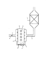
連続再生型DPFは、図2に示すように、エンジンaの排気通路bに排気ガス中のPMを捕集するフィルタcを設け、このフィルタcに捕集されたPMを排気ガスの温度によって連続的に燃焼させ、自己再生するものである。しかし、低速低負荷等の排気ガス温度が低いときには、フィルタcに捕集されたPMを排気ガスの温度によって燃焼させることができないため再生できず、PMがフィルタcに蓄積され続けてしまい、フィルタcが目詰まりして排圧が上昇するという問題が生じる。 As shown in FIG. 2, the continuous regeneration type DPF is provided with a filter c for collecting PM in the exhaust gas in the exhaust passage b of the engine a, and the PM collected in the filter c is continuously changed according to the temperature of the exhaust gas. It burns automatically and regenerates itself. However, when the exhaust gas temperature such as low speed and low load is low, the PM collected in the filter c cannot be combusted by the temperature of the exhaust gas and cannot be regenerated, and the PM continues to be accumulated in the filter c. There is a problem that c is clogged and the exhaust pressure increases.
そこで、上記フィルタcを触媒担持フィルタc’とし、この触媒担持フィルタc’に燃料の未燃成分を供給する技術が知られている。この技術によれば、触媒担持フィルタc’が燃料未燃成分によって活性化されて昇温するので、低速低負荷等の排気ガスの温度が比較的低い場合であっても、触媒担持フィルタc’を強制的に再生できる。 Therefore, a technique is known in which the filter c is used as a catalyst-carrying filter c 'and an unburned component of fuel is supplied to the catalyst-carrying filter c'. According to this technique, since the catalyst-carrying filter c ′ is activated by the unburned fuel component and rises in temperature, the catalyst-carrying filter c ′ can be used even when the temperature of the exhaust gas such as low speed and low load is relatively low. Can be played forcibly.
触媒担持フィルタc’への燃料未燃成分の供給は、本発明者等は、インジェクタdからシリンダ内にマルチ噴射やポスト噴射を行って達成している。マルチ噴射とは、メイン噴射の後にメイン噴射による火炎が継続しているときに1回以上のサブ噴射を行うものであり、ポスト噴射とは、メイン噴射の後にメイン噴射による火炎が消えた後に1回以上のサブ噴射を行うものである。 The present inventors have achieved the supply of unburned fuel components to the catalyst-carrying filter c 'by performing multi-injection or post-injection from the injector d into the cylinder. The multi-injection is to perform one or more sub-injections when the main-injection flame continues after the main-injection. The post-injection is 1 after the main-injection flame has disappeared after the main-injection. Sub-injection more than once.
かかるマルチ噴射・メイン噴射を行って触媒担持フィルタc’の強制再生を行っているとき、EGR弁eを開いて排気還流を実施すると、マルチ噴射・メイン噴射によって生じた燃料未燃成分が排気側からEGR通路fを通って吸気側に還流されるため、その未燃成分がタール状の物質となって吸気マニホールドg等に付着し、最悪では閉塞箇所が生じる可能性がある。よって、触媒担持フィルタc’の強制再生時には、EGR弁eを閉弁し、排気ガスの還流を行わないようにするシステムが考えられる。 When the catalyst-carrying filter c ′ is forcibly regenerated by performing the multi-injection / main injection, if the exhaust gas recirculation is performed by opening the EGR valve e, the unburned fuel components generated by the multi-injection / main injection are exhausted. From the exhaust gas to the intake side through the EGR passage f, the unburned component becomes a tar-like substance and adheres to the intake manifold g and the like, and in the worst case, a blockage portion may occur. Therefore, a system is conceivable in which the EGR valve e is closed during exhaustive regeneration of the catalyst-carrying filter c 'so that the exhaust gas is not recirculated.
なお、関連する先行技術文献として特許文献1及び2が知られているが、特許文献1に記載されたものは、フィルタcを自己再生する際に、吸気通路hに設けられた吸気絞り弁iを閉制御するものであり、特許文献2に記載されたものは、特許文献1の制御に加えてEGR弁eを開放することで新規吸入空気量を減少させてフィルタcを通過する排気ガスの温度を高め、フィルタcの自己再生の効率化を図ったものであり、上記マルチ噴射・メイン噴射を行って触媒担持フィルタc’を昇温させて自己再生を行う上述のシステムとは技術的前提が異なる。
ところで、上述のシステムにおいては、EGR弁eを閉じることで確かに吸気マニホールドgにおける未燃成分の付着・堆積は防止できるものの、閉弁されたEGR弁eよりもEGRガスの流れ方向上流側のEGR通路f及びEGRクーラh等に排気ガスが滞留するため、それらの部分h、fに未燃成分がタール状の物質として堆積することが発覚した。 By the way, in the above-described system, the EGR valve e can be closed to surely prevent adhesion and accumulation of unburned components in the intake manifold g. However, the EGR gas flow upstream of the closed EGR valve e can be prevented. Since exhaust gas stays in the EGR passage f, the EGR cooler h, and the like, it has been found that unburned components accumulate as tar-like substances in the portions h and f.
そこで、本発明の目的は、EGR通路を適宜掃気してEGR通路内に未燃成分が堆積することを回避したエンジンの排気浄化装置を提供することにある。 SUMMARY OF THE INVENTION An object of the present invention is to provide an engine exhaust purification device that appropriately scavenges an EGR passage to avoid accumulation of unburned components in the EGR passage.
上記目的を達成するために創案された請求項1に係る発明は、エンジンの排気通路に設けられ、排気ガス中の粒子状物質を捕集するフィルタと、該フィルタの上流側及び/又は該フィルタの表面に設けられ、燃料の未燃成分が供給されたとき昇温して上記フィルタに捕集された粒子状物質を燃焼して上記フィルタを再生するための触媒と、エンジンの吸気側と排気側とを連通するEGR通路に設けられたEGR弁と、シリンダ内に燃料を噴射するインジェクタと、該インジェクタ及び上記EGR弁を制御する制御手段とを有し、該制御手段は、上記フィルタを再生する場合であって、上記インジェクタの燃料噴射を制御して燃料の未燃成分を上記触媒に供給するとき、上記EGR弁を閉じ、上記フィルタの再生を継続している場合であって、上記インジェクタから燃料を噴射しない状態(例えば減速時等)に移行したときには、上記EGR弁を開くものである。
The invention according to
請求項2に係る発明は、上記制御手段は、上記フィルタを再生する場合、エンジンの吸気通路に設けられた吸気絞り弁を閉制御するものである。 According to a second aspect of the present invention, the control means controls the intake throttle valve provided in the intake passage of the engine to be closed when the filter is regenerated.
請求項3に係る発明は、エンジンの吸気通路に設けられた吸気絞り弁と、エンジンの排気通路に設けられ、排気ガス中の粒子状物質を捕集するフィルタと、該フィルタの上流側及び/又は該フィルタの表面に設けられ、燃料の未燃成分が供給されたとき昇温して上記フィルタに捕集された粒子状物質を燃焼して上記フィルタを再生するための触媒と、エンジンの吸気側と排気側とを連通するEGR通路に設けられたEGR弁と、シリンダ内に燃料を噴射するインジェクタと、該インジェクタ、上記EGR弁及び吸気絞り弁を制御する制御手段とを有し、該制御手段は、上記フィルタの再生時に、上記インジェクタの燃料噴射を制御して燃料の未燃成分を上記触媒に供給し、上記インジェクタから燃料を噴射しないときに、上記吸気絞り弁を閉制御し、上記EGR弁を開制御するものである。 The invention according to claim 3 is an intake throttle valve provided in the intake passage of the engine, a filter provided in the exhaust passage of the engine for collecting particulate matter in the exhaust gas, an upstream side of the filter and / or Or a catalyst provided on the surface of the filter for raising the temperature when an unburned component of the fuel is supplied and burning the particulate matter collected in the filter to regenerate the filter, and the intake air of the engine An EGR valve provided in an EGR passage communicating the exhaust side and the exhaust side, an injector for injecting fuel into the cylinder, and a control means for controlling the injector, the EGR valve and the intake throttle valve, and the control The means controls the fuel injection of the injector during regeneration of the filter to supply unburned components of the fuel to the catalyst, and closes the intake throttle valve when fuel is not injected from the injector. Gyoshi is for opening control of the EGR valve.
本発明によれば次のような効果を発揮できる。 According to the present invention, the following effects can be exhibited.
(1)請求項1に係る発明によれば、燃料の噴射又は排気ガスへの未燃燃料成分の添加を行うフィルタの再生中に、減速要求等によりインジェクタから燃料が噴射されなくなると、それまで閉じられていたEGR弁が開かれるため、EGR通路が燃料が混合されていない空気によって掃気される。これにより、EGR通路内に滞留する未燃成分を、上記空気によって的確に掃気できる。
(1) According to the invention of
(2)請求項2に係る発明によれば、フィルタの再生時に、吸気絞り弁を閉制御するので、新規吸入空気量が減少して排気ガス温度の低下が抑制される。これにより、触媒及び/又はフィルタの温度低下が抑制され、フィルタの再生能力の低下が抑えられる。
(2) According to the invention of
(3)請求項3に係る発明によれば、フィルタの再生時に、インジェクタから燃料を噴射しないときには、吸気絞り弁が閉制御されると共にEGR弁が開制御されるので、吸気絞り弁の閉制御によって新規吸入空気量が減少して触媒及び/又はフィルタの温度低下を抑制できる。更に、吸気絞り弁の閉制御によって生じるシリンダ内の負圧を、EGR弁を開制御することで小さくできるので、オイル上がり・オイル下がりを抑制できる。また、EGR弁を開制御することで、滞留未燃成分を掃気できる。 (3) According to the invention of claim 3, when the fuel is not injected from the injector during regeneration of the filter, the intake throttle valve is controlled to close and the EGR valve is controlled to open. As a result, the amount of new intake air can be reduced, and the temperature drop of the catalyst and / or filter can be suppressed. Furthermore, since the negative pressure in the cylinder caused by the closing control of the intake throttle valve can be reduced by controlling the opening of the EGR valve, it is possible to suppress oil rise and oil fall. Further, the remaining unburned components can be scavenged by controlling the opening of the EGR valve.
以下、本発明の好適な一実施例を添付図面に基づいて詳述する。 Hereinafter, a preferred embodiment of the present invention will be described in detail with reference to the accompanying drawings.
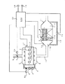
図1に示すように、車両に搭載されるディーゼルエンジン1のシリンダヘッドには、インジェクタ2(図例ではコモンレール式燃料噴射システムのインジェクタ)が装着されている。インジェクタ2は、制御手段としてのECU20(エンジン・コントロール・ユニット)からの信号を受け、その噴射時期及び噴射量が制御される。
As shown in FIG. 1, an injector 2 (in the illustrated example, an injector of a common rail fuel injection system) is attached to a cylinder head of a
エンジン1の吸気通路3には、通路断面積を可変とする吸気絞り弁4が設けられている。吸気絞り弁4の駆動部4aは、ECU20からの信号を受け、吸気絞り弁4を開閉制御する。
The intake passage 3 of the
エンジン1の吸気マニホールド5と排気マニホールド6とは、EGR通路7によって連通されている。EGR通路7には、通路断面積を可変とするEGR弁8が設けられている。EGR弁8の駆動部8aは、ECU20からの信号を受け、EGR弁8を開閉制御する。EGR通路7のEGR弁8の上流側(EGRガスの流れ方向における上流側)には、通路7内を通るEGRガスを冷却するEGRクーラ9が設けられている。
The intake manifold 5 and the
エンジン1の排気通路10には、酸化触媒Aと触媒担持フィルタBとが直列に設けられている。酸化触媒A及び触媒担持フィルタBは、排気通路10に介設された収容ケース11に収容されており、排気ガスの流れの上流側に酸化触媒Aが、それと所定間隔を隔てて下流側に触媒担持フィルタBが配置されている。収容ケース11内は、酸化触媒A及び触媒担持フィルタBにより、上流室11aと中間室11bと下流室11cとに仕切られる。
An oxidation catalyst A and a catalyst-carrying filter B are provided in series in the exhaust passage 10 of the
酸化触媒Aは、全体が酸化触媒物質からなるブロック体からなり、このブロック体には、上流室11aと中間室11bとを連通する細孔が複数設けられている。酸化触媒Aは、燃料の未燃成分が供給されたとき昇温し、下流側の触媒担持フィルタBへと流れる排気ガスを加熱し、触媒担持フィルタBを昇温させる機能を有する。なお、酸化触媒Aは、触媒担持フィルタBの昇温を補助するものなので、後述のように省略することもできる。 The oxidation catalyst A consists of a block body made entirely of an oxidation catalyst material, and the block body is provided with a plurality of pores that communicate the upstream chamber 11a and the intermediate chamber 11b. The oxidation catalyst A has a function of raising the temperature when an unburned component of the fuel is supplied, heating the exhaust gas flowing to the catalyst-carrying filter B on the downstream side, and raising the temperature of the catalyst-carrying filter B. The oxidation catalyst A assists the temperature rise of the catalyst-carrying filter B and can be omitted as will be described later.
触媒担持フィルタBは、中間室11bと下流室11cとを連通する複数の細孔を有し、隣り合う細孔の上流端と下流端とが交互に目封じされており、各細孔の内周面には触媒が担持されている。触媒担持フィルタBは、排気ガス中のPMを細孔の内周面で捕集すると共に、燃料の未燃成分が供給されたとき昇温し、捕集したPMを燃焼させて再生する。 The catalyst-carrying filter B has a plurality of pores communicating with the intermediate chamber 11b and the downstream chamber 11c, and the upstream end and the downstream end of adjacent pores are alternately sealed. A catalyst is supported on the peripheral surface. The catalyst-carrying filter B collects PM in the exhaust gas at the inner peripheral surface of the pores, raises the temperature when an unburned component of the fuel is supplied, and burns and collects the collected PM.
上流室11aと下流室11cとの圧力差は、差圧センサ12によって検出されるようになっている。すなわち、上流室11aと下流室11cとは管13によって連通されており、この管13の途中に左右の管の圧力差を検出する差圧センサ12が設けられている。差圧センサ12の検出値はECU20に出力される。
A pressure difference between the upstream chamber 11a and the downstream chamber 11c is detected by a differential pressure sensor 12. That is, the upstream chamber 11a and the downstream chamber 11c are communicated with each other by a
上流室11aには、酸化触媒Aの入口における排気ガス温度を検出する触媒入口排気温度センサ14が設けられ、中間室11bには、触媒担持フィルタBの入口における排気ガス温度を検出するフィルタ入口排気温度センサ15が設けられている。これらの排気温度センサ14、15の検出値はECU20に出力される。
A catalyst inlet
ECU20には、上記差圧センサ12、排気温度センサ14、15の各検出値に加え、アクセルペダルの開度を検出するアクセルポジションセンサ16の信号、エンジン回転速度を検出する回転速度センサ17の信号、車両の走行距離を検出する距離センサ18の信号が夫々入力されるようになっている。
In addition to the detected values of the differential pressure sensor 12 and the
さて、上記触媒担持フィルタBにはエンジン1の運転によって排気ガス中のPMが捕集されるが、触媒担持フィルタBに再生すべき一定量のPMが捕集されたか否かは、ECU20によって次のように判断される。すなわち、上記距離センサ18によって、以前に触媒担持フィルタBを再生したときから現在までの車両の走行距離を検出し、この走行距離が所定距離になったならば、触媒担持フィルタBに一定量のPMが捕集されたと推定し、再生すべきとの判断がなされる。
The catalyst-carrying filter B collects PM in the exhaust gas as the
但し、車両の走行条件によっては、車両の走行距離が上記所定距離に至る前に、触媒担持フィルタBに一定量のPMが捕集されることもあり得る。このため、上記差圧センサ12によって差圧を常時または所定時間毎に検出しておき、差圧が所定差圧を超えたときにも、触媒担持フィルタBに一定量のPMが捕集されたと推定し、再生すべきとの判断がなされる。 However, depending on the traveling condition of the vehicle, a certain amount of PM may be collected in the catalyst-carrying filter B before the traveling distance of the vehicle reaches the predetermined distance. For this reason, when the differential pressure is detected by the differential pressure sensor 12 at regular intervals or every predetermined time, and when the differential pressure exceeds the predetermined differential pressure, a certain amount of PM is collected in the catalyst-carrying filter B. It is estimated and judged to be regenerated.
ECU20は、触媒担持フィルタBを再生しないと判断したときには、アクセルポジションセンサ16の信号及び回転速度センサ17の信号に基づいて、通常の燃料噴射を行う信号をインジェクタ2へ出力する。また、触媒担持フィルタBを再生すべきと判断したときには、触媒入口排気温度センサ14及びフィルタ入口排気温度センサ15の検出値に応じて、次のように通常噴射、マルチ噴射、ポスト噴射を切り替え、再生を行う。マルチ噴射、ポスト噴射については、背景技術の欄で説明した通りである。
When it is determined that the catalyst-carrying filter B is not regenerated, the
マルチ噴射・ポスト噴射は、通常走行時やアイドリング時等、燃料噴射が実行されるときに行われ、降坂走行中にアクセルペダルをオフしたときや減速すべくアクセルペダルをオフしたとき等、燃料噴射がカットされたときには行われない。マルチ噴射・ポスト噴射は、メイン噴射の後にサブ噴射を行うものであるので、そもそもメイン噴射を行わない燃料カット時には、当然行われないのである。 Multi-injection and post-injection are performed when fuel injection is performed during normal driving, idling, etc., and when the accelerator pedal is turned off during downhill driving or when the accelerator pedal is turned off for deceleration. It is not done when the injection is cut. Since the multi-injection / post-injection is a sub-injection after the main injection, it is naturally not performed when the fuel is cut without the main injection.
触媒入口排気温度センサ14で検出される排気ガスの温度が第1所定温度(酸化触媒Aの活性温度:例えば約250℃)よりも低い場合には、先ず、マルチ噴射を行う。これにより、動力に変換されない廃熱が酸化触媒Aに供給され、酸化触媒Aが活性化する温度まで昇温する。
When the temperature of the exhaust gas detected by the catalyst inlet
その後、ポスト噴射を行い、未燃成分を含む排気ガスを酸化触媒A及び触媒担持フィルタBに供給する。これにより、上記排気ガスが酸化触媒Aで昇温され、高温ガスとなって触媒担持フィルタBへ供給され、触媒担持フィルタBが活性化されて昇温(約500〜600℃)する。この結果、触媒担持フィルタBに捕集されたPMが燃焼され、触媒担持フィルタBが強制的に再生される。 Thereafter, post injection is performed, and exhaust gas containing unburned components is supplied to the oxidation catalyst A and the catalyst-carrying filter B. Thereby, the exhaust gas is heated by the oxidation catalyst A and supplied to the catalyst-carrying filter B as a high-temperature gas, and the catalyst-carrying filter B is activated and heated (about 500 to 600 ° C.). As a result, the PM collected by the catalyst-carrying filter B is burned, and the catalyst-carrying filter B is forcibly regenerated.
なお、ポスト噴射を行うときに同時にマルチ噴射を行ってもよい。また、ポスト噴射は、フィルタ入口排気温度センサ15の検出温度が第2所定温度(例えば約300℃)になった後に行うようにしてもよい。 Note that multi-injection may be performed simultaneously with post-injection. Further, the post injection may be performed after the temperature detected by the filter inlet exhaust temperature sensor 15 reaches the second predetermined temperature (for example, about 300 ° C.).
ポスト噴射及びマルチ噴射を行って触媒担持フィルタBを再生するときには、EGR弁8がECU20によって閉じられ、排気ガスの吸気側への還流が中止される。EGR弁8が開かれていると、ポスト噴射及びマルチ噴射による未燃成分が吸気側に還流されてしまい、この未燃成分がタール状の物質となって吸気マニホールド5等に付着するため、EGR弁8を閉じることでこれを回避しているのである。
When the post-injection and multi-injection are performed to regenerate the catalyst-carrying filter B, the
但し、このようにEGR弁8を閉じたとしても、閉弁されたEGR弁8よりもEGRガスの流れ方向上流側のEGR通路7及びEGRクーラ9等に排気ガスが滞留するため、それらの部分7、9に未燃燃料がタール状の物質として堆積してしまう。
However, even if the
そこで、本実施形態では、触媒担持フィルタBの再生中、車両減速時等にアクセルペダルがオフされる等してインジェクタ2から燃料が噴射されなくなったときには、それまで閉じられていたEGR弁8をECU20によって開くようにしている。
Therefore, in the present embodiment, when the fuel is no longer injected from the
すると、インジェクタ2が無噴射であることから燃料が混合されていない空気(排気)が、排気マニホールド6からEGR通路7を通って吸気マニホールド5に還流され、EGR通路7やEGRクーラ9内に滞留していた未燃成分を、燃料が混合されていない空気によって的確に掃気できる。これにより、EGR通路7やEGRクーラ9内に未燃成分がタール状に堆積することを回避できる。
Then, since the
すなわち、触媒担持フィルタBの再生中、燃料噴射がなされるときにはマルチ噴射・ポスト噴射を行って触媒担持フィルタBに未燃成分を供給すると共に、EGR弁8を基本的には全閉として未燃成分の吸気マニホールド5への付着・堆積を防止する。そして、アクセルペダルオフ時等のインジェクタ2の無噴射時には、EGR弁8を開いてEGR通路7及びEGRクーラ9を燃料が混合されていない空気によって掃気し、EGR通路7及びEGRクーラ9に滞留した未燃成分を除去する。
That is, during the regeneration of the catalyst-carrying filter B, when fuel is injected, multi-injection / post-injection is performed to supply unburned components to the catalyst-carrying filter B, and the
他方、触媒担持フィルタBの再生中、吸気絞り弁4をECU20によって閉制御(全閉も含む)してもよい。ここで、吸気絞り弁4の全閉とは吸入空気が多少通過できるものである。これにより、新規吸入空気量が減少するため、触媒担持フィルタBを通過する排気ガス温度の低下を抑制でき、触媒担持フィルタBの温度低下が抑制され、その再生能力の低下が抑えられる。
On the other hand, during regeneration of the catalyst-carrying filter B, the
ところで、このような吸気絞り弁4の閉制御は、EGR弁8を閉じているとき(即ちポスト噴射・マルチ噴射を行っているとき)のみ実行してもよい。何故なら、ポスト噴射・マルチ噴射により生じた未燃燃料を、吸気絞り弁4を閉制御して新規吸入空気量が減少させることで、その濃度を低下させることなく触媒担持フィルタBに供給できるからである。
By the way, such closing control of the
また、触媒担持フィルタBの再生時における燃料無噴射時に、吸気絞り弁4を閉制御(全閉を含む)し、EGR弁8を開制御してもよい。こうすれば、吸気絞り弁4の閉制御によって新規吸入空気量が減少して触媒担持フィルタBの温度低下を抑制でき、同時に、吸気絞り弁4の閉制御によって生じるシリンダ内の負圧を、EGR弁8を開制御して吸気マニホールド5と排気マニホールド6とを連通することで小さくできるので、シリンダ内におけるオイル上がり・オイル下がりを抑制できる。
Further, when no fuel is injected during regeneration of the catalyst-carrying filter B, the
すなわち、吸気絞り弁4を閉制御したとき、EGR弁8の閉状態を維持すると、吸気絞り弁4の閉制御によってシリンダ内の負圧が大きくなるため、オイル上がりやオイル下がりが生じてオイル消費量が悪化してしまう。そこで、吸気絞り弁4の閉制御したとき同時にEGR弁8を開くことでシリンダ内の負圧を小さくし、オイル上がりやオイル下がりを抑制してオイル消費量を抑えているのである。
That is, when the
ここで、オイル上がりとは、クランクケース内のオイルがシリンダとピストンとの間を通ってピストン上方の燃焼室内に移動することであり、オイル下がりとは、シリンダヘッド内のオイルがバルブステムとバルブガイドとの間等を通って燃焼室内に移動することである。 Here, the oil rising means that the oil in the crankcase moves between the cylinder and the piston and moves into the combustion chamber above the piston, and the oil falling means that the oil in the cylinder head moves from the valve stem to the valve. It moves to the combustion chamber through the space between the guide and the like.
また、EGR弁8を開くことで、EGR通路7及びEGRクーラ9に滞留した未燃成分を掃気できる。
Further, by opening the
本発明は、上記実施形態に限定されるものではない。 The present invention is not limited to the above embodiment.
例えば、上記実施形態においては、収容ケース11内に酸化触媒A及び触媒担持フィルタBを設けているが、酸化触媒Aを設けずに触媒担持フィルタBのみを設けた構成としてもよい。この構成においても、マルチ噴射及び/又はポスト噴射によって触媒担持フィルタBを再生可能な温度まで昇温させることが可能である。
For example, in the above-described embodiment, the oxidation catalyst A and the catalyst-carrying filter B are provided in the
また、収容ケース11内に、酸化触媒Aを設けると共に、その下流側に触媒を担持しないフィルタを設けた構成としてもよい。この構成においても、マルチ噴射及び/又はポスト噴射によって酸化触媒Aを昇温させ、フィルタを再生可能な温度まで昇温させることが可能である。
Moreover, it is good also as a structure which provided the oxidation catalyst A in the
また、インジェクタ2はコモンレール式のものでなくても構わない。また、差圧センサ12は、上流室11aと下流室11cとに夫々圧力センサを設け、それらの出力値の差を用いるものでもよい。
The
1 エンジン
2 インジェクタ
3 吸気通路
4 吸気絞り弁
7 EGR通路
8 EGR弁
10 排気通路
B 触媒担持フィルタ
20 制御手段としてのECU
DESCRIPTION OF
Claims (3)
該フィルタの上流側及び/又は該フィルタの表面に設けられ、燃料の未燃成分が供給されたとき昇温して上記フィルタに捕集された粒子状物質を燃焼して上記フィルタを再生するための触媒と、
エンジンの吸気側と排気側とを連通するEGR通路に設けられたEGR弁と、
シリンダ内に燃料を噴射するインジェクタと、
該インジェクタ及び上記EGR弁を制御する制御手段とを有し、
該制御手段は、
上記フィルタを再生する場合であって、上記インジェクタの燃料噴射を制御して燃料の未燃成分を上記触媒に供給するとき、上記EGR弁を閉じ、
上記フィルタの再生を継続している場合であって、上記インジェクタから燃料を噴射しない状態に移行したときには、上記EGR弁を開くものであることを特徴とするエンジンの排気浄化装置。 A filter provided in the exhaust passage of the engine for collecting particulate matter in the exhaust gas;
To regenerate the filter by burning the particulate matter collected in the filter by raising the temperature when an unburned component of the fuel is supplied upstream of the filter and / or on the surface of the filter The catalyst of
An EGR valve provided in an EGR passage communicating the intake side and the exhaust side of the engine;
An injector for injecting fuel into the cylinder;
Control means for controlling the injector and the EGR valve,
The control means includes
When regenerating the filter, when the fuel injection of the injector is controlled to supply unburned components of the fuel to the catalyst, the EGR valve is closed,
An exhaust emission control device for an engine, wherein the EGR valve is opened when the regeneration of the filter is continued and the fuel injector is not injected from the injector.
エンジンの排気通路に設けられ、排気ガス中の粒子状物質を捕集するフィルタと、
該フィルタの上流側及び/又は該フィルタの表面に設けられ、燃料の未燃成分が供給されたとき昇温して上記フィルタに捕集された粒子状物質を燃焼して上記フィルタを再生するための触媒と、
エンジンの吸気側と排気側とを連通するEGR通路に設けられたEGR弁と、
シリンダ内に燃料を噴射するインジェクタと、
該インジェクタ、上記EGR弁及び吸気絞り弁を制御する制御手段とを有し、
該制御手段は、
上記フィルタの再生時に、上記インジェクタの燃料噴射を制御して燃料の未燃成分を上記触媒に供給し、上記インジェクタから燃料を噴射しないときに、上記吸気絞り弁を閉制御し、上記EGR弁を開制御することを特徴とするエンジンの排気浄化装置。
An intake throttle valve provided in the intake passage of the engine;
A filter provided in the exhaust passage of the engine for collecting particulate matter in the exhaust gas;
To regenerate the filter by burning the particulate matter collected in the filter by raising the temperature when an unburned component of the fuel is supplied upstream of the filter and / or on the surface of the filter The catalyst of
An EGR valve provided in an EGR passage communicating the intake side and the exhaust side of the engine;
An injector for injecting fuel into the cylinder;
Control means for controlling the injector, the EGR valve and the intake throttle valve,
The control means includes
During regeneration of the filter, the fuel injection of the injector is controlled to supply unburned components of the fuel to the catalyst, and when the fuel is not injected from the injector, the intake throttle valve is closed and the EGR valve is An exhaust emission control device for an engine characterized by performing open control.
Priority Applications (5)
| Application Number | Priority Date | Filing Date | Title |
|---|---|---|---|
| JP2004115815A JP4196872B2 (en) | 2004-04-09 | 2004-04-09 | Engine exhaust purification system |
| EP20050007097 EP1584805B1 (en) | 2004-04-09 | 2005-03-31 | Engine exhaust gas purification device |
| CNB2005100600783A CN100572769C (en) | 2004-04-09 | 2005-03-31 | Engine Exhaust Purification Device |
| CN2008101821768A CN101408120B (en) | 2004-04-09 | 2005-03-31 | Exhaust gas purification apparatus for engine |
| US11/099,029 US7716920B2 (en) | 2004-04-09 | 2005-04-05 | Engine exhaust gas purification device |
Applications Claiming Priority (1)
| Application Number | Priority Date | Filing Date | Title |
|---|---|---|---|
| JP2004115815A JP4196872B2 (en) | 2004-04-09 | 2004-04-09 | Engine exhaust purification system |
Publications (2)
| Publication Number | Publication Date |
|---|---|
| JP2005299480A true JP2005299480A (en) | 2005-10-27 |
| JP4196872B2 JP4196872B2 (en) | 2008-12-17 |
Family
ID=34909551
Family Applications (1)
| Application Number | Title | Priority Date | Filing Date |
|---|---|---|---|
| JP2004115815A Expired - Fee Related JP4196872B2 (en) | 2004-04-09 | 2004-04-09 | Engine exhaust purification system |
Country Status (4)
| Country | Link |
|---|---|
| US (1) | US7716920B2 (en) |
| EP (1) | EP1584805B1 (en) |
| JP (1) | JP4196872B2 (en) |
| CN (2) | CN100572769C (en) |
Cited By (6)
| Publication number | Priority date | Publication date | Assignee | Title |
|---|---|---|---|---|
| JP2008196445A (en) * | 2007-02-15 | 2008-08-28 | Toyota Motor Corp | Control device for internal combustion engine |
| JP2010144625A (en) * | 2008-12-18 | 2010-07-01 | Mazda Motor Corp | Exhaust emission control device of engine |
| JP2011252474A (en) * | 2010-06-04 | 2011-12-15 | Mazda Motor Corp | Method and device for controlling engine |
| KR101405752B1 (en) * | 2008-07-22 | 2014-06-10 | 현대자동차주식회사 | Particulate matters cleaning device for exhaust gas recirculation |
| CN108457718A (en) * | 2017-02-21 | 2018-08-28 | 丰田自动车株式会社 | The control device of internal combustion engine |
| JP2025085210A (en) * | 2023-11-24 | 2025-06-05 | いすゞ自動車株式会社 | vehicle |
Families Citing this family (24)
| Publication number | Priority date | Publication date | Assignee | Title |
|---|---|---|---|---|
| JP3821154B1 (en) * | 2005-03-16 | 2006-09-13 | いすゞ自動車株式会社 | Exhaust gas purification method and exhaust gas purification system |
| JP4463144B2 (en) * | 2005-05-13 | 2010-05-12 | 本田技研工業株式会社 | Exhaust gas purification device for internal combustion engine |
| JP3988776B2 (en) * | 2005-07-15 | 2007-10-10 | いすゞ自動車株式会社 | Exhaust gas purification system control method and exhaust gas purification system |
| JP4415963B2 (en) * | 2006-03-17 | 2010-02-17 | トヨタ自動車株式会社 | Exhaust gas purification device for internal combustion engine |
| FR2910058B1 (en) * | 2006-12-14 | 2011-03-04 | Renault Sas | METHOD FOR LIMITING AIR INTAKE NOISE PRODUCED AT THE END OF REGENERATION OF THE EXHAUST GAS POST-TREATMENT SYSTEM |
| JP2009138704A (en) * | 2007-12-10 | 2009-06-25 | Mitsubishi Fuso Truck & Bus Corp | Exhaust emission aftertreatment device |
| JP5024066B2 (en) | 2008-01-16 | 2012-09-12 | 株式会社デンソー | Exhaust gas purification device for internal combustion engine |
| JP4277933B1 (en) * | 2008-06-11 | 2009-06-10 | トヨタ自動車株式会社 | INTERNAL COMBUSTION ENGINE DEVICE, ITS CONTROL METHOD, AND VEHICLE |
| JP4852127B2 (en) * | 2009-06-25 | 2012-01-11 | 日立建機株式会社 | Work machine |
| GB2472816B (en) * | 2009-08-19 | 2013-10-16 | Gm Global Tech Operations Inc | Method for regenerating a diesel particulate filter |
| JP5523028B2 (en) * | 2009-09-04 | 2014-06-18 | 日立建機株式会社 | Hydraulic drive device for hydraulic work machine |
| KR101774303B1 (en) * | 2010-05-07 | 2017-09-04 | 얀마 가부시키가이샤 | Exhaust gas purification system |
| DE102011006920A1 (en) * | 2011-04-07 | 2012-10-11 | Robert Bosch Gmbh | Method for controlling regeneration of diesel particulate filter in exhaust gas passage of diesel engine of vehicle, involves carrying out regeneration process in extended regeneration phase without utilizing post-injections |
| FR2977004A1 (en) * | 2011-06-27 | 2012-12-28 | Cmi Thermline Services | DEVICE AND METHOD FOR MANAGING IMBULES FOR REGENERATIVE BURNERS, BURNER COMPRISING SUCH A DEVICE |
| US20130160432A1 (en) * | 2011-09-28 | 2013-06-27 | International Engine Intellectual Property Company Llc | Limiting nox emissions |
| US20130086887A1 (en) * | 2011-10-07 | 2013-04-11 | Nathaniel D. Bergland | Method For Reducing The Rate Of Exhaust Heat Loss |
| JP5869387B2 (en) * | 2012-03-19 | 2016-02-24 | 本田技研工業株式会社 | Control device for internal combustion engine |
| GB2504359B (en) | 2012-07-27 | 2016-01-06 | Perkins Engines Co Ltd | Method of controlling operation of an engine having both an exhaust fluid recirculation apparatus and an exhaust fluid treatment apparatus |
| CN107762653B (en) * | 2017-10-10 | 2020-03-17 | 中国第一汽车股份有限公司 | Temperature control system of diesel oxidation catalyst |
| JP7159876B2 (en) * | 2019-01-08 | 2022-10-25 | トヨタ自動車株式会社 | Exhaust purification device for internal combustion engine |
| US10920695B1 (en) * | 2019-09-05 | 2021-02-16 | Ford Global Technologies, Llc | Methods and systems for regeneration of an exhaust aftertreatment device |
| JP7264111B2 (en) * | 2020-05-19 | 2023-04-25 | トヨタ自動車株式会社 | Exhaust purification device |
| US11840980B1 (en) * | 2022-08-04 | 2023-12-12 | International Engine Intellectual Property Company, Llc | Systems and methods for selective hydrocarbon injection |
| CN119633514B (en) * | 2025-02-05 | 2025-08-29 | 上海湉蓓科技有限公司 | A chemical waste gas treatment and purification equipment |
Family Cites Families (28)
| Publication number | Priority date | Publication date | Assignee | Title |
|---|---|---|---|---|
| US4345431A (en) * | 1980-03-25 | 1982-08-24 | Shimizu Construction Co. Ltd. | Exhaust gas cleaning system for diesel engines |
| JPS5786536A (en) * | 1980-11-17 | 1982-05-29 | Toyota Motor Corp | Reproduction method of particle catcher and fuel supplier for diesel engine |
| JPS5851235A (en) | 1981-09-18 | 1983-03-25 | Toyota Motor Corp | Control device for suction air choking valve in diesel engine |
| DE3909932A1 (en) | 1989-03-25 | 1990-09-27 | Daimler Benz Ag | METHOD FOR REGENERATING A PARTICLE FILTER ARRANGED IN THE EXHAUST PIPE OF A CHARGED COMBUSTION ENGINE |
| DE3912301A1 (en) * | 1989-04-14 | 1990-10-25 | Daimler Benz Ag | METHOD FOR REGENERATING A CARBON PARTICLE FILTER ARRANGED IN THE EXHAUST PIPE OF AN AIR COMPRESSING INTERNAL COMBUSTION ENGINE |
| JP3211215B2 (en) | 1991-07-12 | 2001-09-25 | 東亞合成株式会社 | Method for producing crystalline zirconium phosphate compound |
| JPH05106518A (en) | 1991-10-16 | 1993-04-27 | Nissan Motor Co Ltd | Exhaust gas reflux device of diesel engine |
| JP2582972B2 (en) | 1991-11-12 | 1997-02-19 | 日産自動車株式会社 | Exhaust recirculation system for diesel engine |
| JP3348659B2 (en) * | 1998-02-13 | 2002-11-20 | 三菱自動車工業株式会社 | In-cylinder injection internal combustion engine |
| US6269791B1 (en) * | 1998-07-22 | 2001-08-07 | Toyota Jidosha Kabushiki Kaisha | Control system for an internal combustion engine |
| WO2000068554A1 (en) * | 1999-05-07 | 2000-11-16 | Toyota Jidosha Kabushiki Kaisha | Exhaust emission control device of internal combustion engine |
| JP3558022B2 (en) * | 2000-01-11 | 2004-08-25 | トヨタ自動車株式会社 | Exhaust gas purification device for internal combustion engine |
| DE10010032A1 (en) * | 2000-03-02 | 2001-10-25 | Volkswagen Ag | Method and device for carrying out a NO¶x¶ regeneration of a NO¶x¶ storage catalytic converter arranged in an exhaust gas duct of an internal combustion engine |
| DE10010031B4 (en) * | 2000-03-02 | 2011-06-09 | Volkswagen Ag | Method and device for carrying out a NOx regeneration of an arranged in an exhaust passage of an internal combustion engine NOx storage catalyst |
| DE60107765T2 (en) * | 2000-06-29 | 2005-05-12 | Toyota Jidosha K.K., Toyota | Device for cleaning the exhaust gas of an internal combustion engine |
| EP1203869B1 (en) * | 2000-11-03 | 2002-08-21 | Ford Global Technologies, Inc., A subsidiary of Ford Motor Company | Control apparatus and method for interrupting regeneration of a particle filter of a Diesel engine |
| DE50001415D1 (en) * | 2000-11-03 | 2003-04-10 | Ford Global Tech Inc | Process for the regeneration of the particle filter of a diesel engine |
| US6598387B2 (en) * | 2000-12-21 | 2003-07-29 | Ford Global Technologies, Llc | Reduction of exhaust smoke emissions following extended diesel engine idling |
| US6497095B2 (en) * | 2000-12-21 | 2002-12-24 | Ford Global Technologies, Inc. | Regeneration of diesel engine particulate filter only above low fuel levels |
| JP4352635B2 (en) * | 2001-06-07 | 2009-10-28 | 株式会社デンソー | Exhaust gas purification device for internal combustion engine |
| US6536209B2 (en) * | 2001-06-26 | 2003-03-25 | Caterpillar Inc | Post injections during cold operation |
| JP3959600B2 (en) | 2001-07-18 | 2007-08-15 | 三菱ふそうトラック・バス株式会社 | Exhaust gas purification device for internal combustion engine |
| DE60238235D1 (en) * | 2001-09-07 | 2010-12-23 | Mitsubishi Motors Corp | Device for exhaust emission control of an engine |
| DE10215479A1 (en) * | 2002-04-09 | 2003-10-23 | Opel Adam Ag | Operating combustion engine with exhaust gas feedback, exhaust gas analyzer and thrust cut-off involves controlling exhaust feedback valve depending on engine braking mode and catalyser temperature |
| JP2003336549A (en) * | 2002-05-20 | 2003-11-28 | Denso Corp | Egr device for internal combustion engine |
| JP3985053B2 (en) * | 2002-07-15 | 2007-10-03 | マツダ株式会社 | Engine exhaust particle processing equipment |
| JP2004293339A (en) * | 2003-03-25 | 2004-10-21 | Mitsubishi Fuso Truck & Bus Corp | Exhaust emission control device |
| JP4139259B2 (en) * | 2003-04-08 | 2008-08-27 | 日野自動車株式会社 | Particulate filter regeneration method |
-
2004
- 2004-04-09 JP JP2004115815A patent/JP4196872B2/en not_active Expired - Fee Related
-
2005
- 2005-03-31 CN CNB2005100600783A patent/CN100572769C/en not_active Expired - Fee Related
- 2005-03-31 CN CN2008101821768A patent/CN101408120B/en not_active Expired - Fee Related
- 2005-03-31 EP EP20050007097 patent/EP1584805B1/en not_active Ceased
- 2005-04-05 US US11/099,029 patent/US7716920B2/en not_active Expired - Fee Related
Cited By (7)
| Publication number | Priority date | Publication date | Assignee | Title |
|---|---|---|---|---|
| JP2008196445A (en) * | 2007-02-15 | 2008-08-28 | Toyota Motor Corp | Control device for internal combustion engine |
| KR101405752B1 (en) * | 2008-07-22 | 2014-06-10 | 현대자동차주식회사 | Particulate matters cleaning device for exhaust gas recirculation |
| JP2010144625A (en) * | 2008-12-18 | 2010-07-01 | Mazda Motor Corp | Exhaust emission control device of engine |
| JP2011252474A (en) * | 2010-06-04 | 2011-12-15 | Mazda Motor Corp | Method and device for controlling engine |
| CN108457718A (en) * | 2017-02-21 | 2018-08-28 | 丰田自动车株式会社 | The control device of internal combustion engine |
| CN108457718B (en) * | 2017-02-21 | 2020-06-30 | 丰田自动车株式会社 | Control device for internal combustion engine |
| JP2025085210A (en) * | 2023-11-24 | 2025-06-05 | いすゞ自動車株式会社 | vehicle |
Also Published As
| Publication number | Publication date |
|---|---|
| CN100572769C (en) | 2009-12-23 |
| CN101408120A (en) | 2009-04-15 |
| EP1584805B1 (en) | 2015-05-06 |
| CN101408120B (en) | 2012-06-13 |
| EP1584805A2 (en) | 2005-10-12 |
| US7716920B2 (en) | 2010-05-18 |
| CN1680690A (en) | 2005-10-12 |
| EP1584805A3 (en) | 2006-12-06 |
| US20050223697A1 (en) | 2005-10-13 |
| JP4196872B2 (en) | 2008-12-17 |
Similar Documents
| Publication | Publication Date | Title |
|---|---|---|
| JP4196872B2 (en) | Engine exhaust purification system | |
| JP4404531B2 (en) | A method for initiating particulate filter regeneration for a direct injection diesel engine using a common rail injection system. | |
| JP4928335B2 (en) | Exhaust purification device | |
| JP2011256843A (en) | Exhaust emission control system | |
| US8549843B2 (en) | Method of controlling exhaust gas purification system and exhaust gas purification system | |
| US9067160B2 (en) | Exhaust gas purification system | |
| EP1555401B1 (en) | Exhaust purifying apparatus for internal combustion engine | |
| JP4379314B2 (en) | Exhaust gas purification device for internal combustion engine | |
| JP4012043B2 (en) | Particulate filter regeneration method | |
| JP5887991B2 (en) | Exhaust purification equipment | |
| JP2007023791A (en) | Exhaust gas purification device for internal combustion engine | |
| JP5516888B2 (en) | Exhaust gas purification device for internal combustion engine | |
| JP2011247140A (en) | Exhaust emission control system for highland | |
| JP4412049B2 (en) | Diesel engine exhaust gas aftertreatment device | |
| JP2018096314A (en) | Internal combustion engine system | |
| JP5478276B2 (en) | Particulate filter regeneration method | |
| JP4489504B2 (en) | Diesel engine exhaust purification system | |
| JP2004176636A (en) | Exhaust purification device for internal combustion engine | |
| JP2005163652A (en) | Exhaust purification equipment | |
| JP2007023876A (en) | Exhaust gas purification system control method and exhaust gas purification system | |
| JP2024077201A (en) | Catalyst deterioration diagnostic device for internal combustion engine | |
| JP5625476B2 (en) | DPF system | |
| JP5286672B2 (en) | Exhaust gas purification device for in-vehicle diesel engine | |
| JP4811024B2 (en) | Exhaust gas purification filter regeneration start timing control device and regeneration start timing control method | |
| JP2011220252A (en) | Method and device for controlling combustion temperature increase of after-treatment burner system |
Legal Events
| Date | Code | Title | Description |
|---|---|---|---|
| A977 | Report on retrieval |
Free format text: JAPANESE INTERMEDIATE CODE: A971007 Effective date: 20080214 |
|
| A131 | Notification of reasons for refusal |
Free format text: JAPANESE INTERMEDIATE CODE: A131 Effective date: 20080311 |
|
| A521 | Request for written amendment filed |
Free format text: JAPANESE INTERMEDIATE CODE: A523 Effective date: 20080512 |
|
| TRDD | Decision of grant or rejection written | ||
| A01 | Written decision to grant a patent or to grant a registration (utility model) |
Free format text: JAPANESE INTERMEDIATE CODE: A01 Effective date: 20080909 |
|
| A01 | Written decision to grant a patent or to grant a registration (utility model) |
Free format text: JAPANESE INTERMEDIATE CODE: A01 |
|
| A61 | First payment of annual fees (during grant procedure) |
Free format text: JAPANESE INTERMEDIATE CODE: A61 Effective date: 20080922 |
|
| FPAY | Renewal fee payment (event date is renewal date of database) |
Free format text: PAYMENT UNTIL: 20111010 Year of fee payment: 3 |
|
| R150 | Certificate of patent or registration of utility model |
Ref document number: 4196872 Country of ref document: JP Free format text: JAPANESE INTERMEDIATE CODE: R150 |
|
| FPAY | Renewal fee payment (event date is renewal date of database) |
Free format text: PAYMENT UNTIL: 20121010 Year of fee payment: 4 |
|
| FPAY | Renewal fee payment (event date is renewal date of database) |
Free format text: PAYMENT UNTIL: 20121010 Year of fee payment: 4 |
|
| FPAY | Renewal fee payment (event date is renewal date of database) |
Free format text: PAYMENT UNTIL: 20131010 Year of fee payment: 5 |
|
| LAPS | Cancellation because of no payment of annual fees |