JP2005298078A - Paper sheet feeding method and device - Google Patents
Paper sheet feeding method and device Download PDFInfo
- Publication number
- JP2005298078A JP2005298078A JP2004112555A JP2004112555A JP2005298078A JP 2005298078 A JP2005298078 A JP 2005298078A JP 2004112555 A JP2004112555 A JP 2004112555A JP 2004112555 A JP2004112555 A JP 2004112555A JP 2005298078 A JP2005298078 A JP 2005298078A
- Authority
- JP
- Japan
- Prior art keywords
- paper sheet
- paper
- sheet
- suction belt
- back gate
- Prior art date
- Legal status (The legal status is an assumption and is not a legal conclusion. Google has not performed a legal analysis and makes no representation as to the accuracy of the status listed.)
- Pending
Links
- 238000000034 method Methods 0.000 title claims abstract description 12
- 210000000078 claw Anatomy 0.000 claims abstract description 8
- 230000008569 process Effects 0.000 claims abstract description 8
- 238000005520 cutting process Methods 0.000 claims abstract description 3
- 230000007246 mechanism Effects 0.000 claims description 4
- 238000005452 bending Methods 0.000 claims 1
- 238000012423 maintenance Methods 0.000 abstract description 3
- 238000004519 manufacturing process Methods 0.000 abstract description 3
- 238000005299 abrasion Methods 0.000 abstract 2
- 230000000694 effects Effects 0.000 description 6
- 230000009471 action Effects 0.000 description 5
- 230000003028 elevating effect Effects 0.000 description 5
- 238000004080 punching Methods 0.000 description 3
- 230000008878 coupling Effects 0.000 description 2
- 238000010168 coupling process Methods 0.000 description 2
- 238000005859 coupling reaction Methods 0.000 description 2
- 238000007664 blowing Methods 0.000 description 1
- 239000000919 ceramic Substances 0.000 description 1
- 230000007547 defect Effects 0.000 description 1
- 238000010586 diagram Methods 0.000 description 1
- 238000000605 extraction Methods 0.000 description 1
- 230000007774 longterm Effects 0.000 description 1
- 239000000463 material Substances 0.000 description 1
- 230000004044 response Effects 0.000 description 1
- 238000005096 rolling process Methods 0.000 description 1
- 230000032258 transport Effects 0.000 description 1
Images
Classifications
-
- B—PERFORMING OPERATIONS; TRANSPORTING
- B65—CONVEYING; PACKING; STORING; HANDLING THIN OR FILAMENTARY MATERIAL
- B65H—HANDLING THIN OR FILAMENTARY MATERIAL, e.g. SHEETS, WEBS, CABLES
- B65H3/00—Separating articles from piles
- B65H3/08—Separating articles from piles using pneumatic force
- B65H3/12—Suction bands, belts, or tables moving relatively to the pile
- B65H3/124—Suction bands or belts
- B65H3/126—Suction bands or belts separating from the bottom of pile
-
- B—PERFORMING OPERATIONS; TRANSPORTING
- B65—CONVEYING; PACKING; STORING; HANDLING THIN OR FILAMENTARY MATERIAL
- B65H—HANDLING THIN OR FILAMENTARY MATERIAL, e.g. SHEETS, WEBS, CABLES
- B65H3/00—Separating articles from piles
- B65H3/34—Article-retaining devices controlling the release of the articles to the separators
-
- B—PERFORMING OPERATIONS; TRANSPORTING
- B65—CONVEYING; PACKING; STORING; HANDLING THIN OR FILAMENTARY MATERIAL
- B65H—HANDLING THIN OR FILAMENTARY MATERIAL, e.g. SHEETS, WEBS, CABLES
- B65H2403/00—Power transmission; Driving means
- B65H2403/50—Driving mechanisms
- B65H2403/51—Cam mechanisms
-
- B—PERFORMING OPERATIONS; TRANSPORTING
- B65—CONVEYING; PACKING; STORING; HANDLING THIN OR FILAMENTARY MATERIAL
- B65H—HANDLING THIN OR FILAMENTARY MATERIAL, e.g. SHEETS, WEBS, CABLES
- B65H2403/00—Power transmission; Driving means
- B65H2403/90—Machine drive
- B65H2403/94—Other features of machine drive
- B65H2403/942—Bidirectional powered handling device
Landscapes
- Engineering & Computer Science (AREA)
- Mechanical Engineering (AREA)
- Sheets, Magazines, And Separation Thereof (AREA)
Abstract
Description
本発明は、紙山の最下部から紙葉を1枚ずつ抜き出し、後続工程に供給する、いわゆるボトムフィーダについての改良方法及びそれに用いる紙葉給送装置に関するものである。 The present invention relates to an improved method for a so-called bottom feeder in which paper sheets are extracted one by one from the lowermost part of a paper pile and supplied to a subsequent process, and a paper sheet feeding device used therefor.
紙山の最下部から紙葉を1枚ずつ抜き出し、印刷装置や型抜き装置に供給する装置、いわゆるボトムフィーダは以前から知られており、例えば給送すべき紙葉類の給送方向前縁部を規制する壁部及び取出し側最前部にある紙葉類の給送方向先端部を係止する鉤部を有してなる支持ブロックと、この支持ブロック給送方向先端部が支持された取出し側最前部にある紙葉類の後方向部に吸着面部が面接触し、かつ弾性部材により紙葉類給送方向に沿う前後方向に揺動可能に支持されたピッカと、上記給送すべき紙葉類の給送方向後縁部を規制するとともに、上記ピッカの吸着面部との間で取出し側最前部にある1枚の紙葉類を通過可能とする狭路を形成する狭路形成ブロックと、上記ピッカにより取り出された1枚の紙葉類を他の紙葉類と分離せしめ給送口の送りローラ間に導くように湾曲形成して設けられた案内板と、上記狭路形成ブロックと上記支持ブロックとの間において紙葉類側縁部に対向するように設けられ、紙葉類の側縁部に空気を吹付け紙葉類間に空隙を与えると共に上記ピッカにより上記支持ブロックから採取した紙葉類を上記案内板に添うように湾曲させる空気吹出し部と、紙葉類採り出し命令により駆動され、上記ピッカを紙葉類給送方向に所定距離往復移動させる手段とを具備してなることを特徴とした紙葉類給送装置(特許文献1参照)、積層されたシートを下から順次フィードしていくボトムフィーダにおいて、積層されたシートの前方がわ下端を係止するセンターガイドを設け、シートの後方がわをガイドするバックガイドの下方にシートが1枚通過することができるゲートを形成し、かつ最下方のシートを前記センターガイドによる係止を解除して下方へ落下させると共に前記ゲートへ導き、この後前方へフィードするシート誘導装置を装備したことを特徴とするボトムフィーダ(特許文献2参照)、フロントガイドとバックゲートと両者間に保持された積層シートとを備え、積層シートの最下部のシートの下面を吸着していったん後退させ次に前進させるサクションボックスを設けて下のシートから順次給送するよう構成したボトムフィーダにおいて、上記サクションボックスはシートに対面する上面に吸着部を形成すると共に、この上面より一部が上方に突出する状態で送り出しローラを設けたことを特徴とするボトムフィーダ(特許文献3参照)などがこれまでに提案されている。 A so-called bottom feeder has been known for a long time, for example, a device that pulls out one sheet at a time from the bottom of a paper pile and supplies it to a printing device or a die-cutting device. A support block having a wall portion for restricting the portion and a hook portion for locking the leading end portion in the feeding direction of the paper sheet at the foremost side on the take-out side, and a takeout in which the leading end portion in the support block feeding direction is supported A picker whose suction surface portion is in surface contact with the rearward portion of the paper sheet at the foremost side and supported by an elastic member so as to be swingable in the front-rear direction along the paper sheet feeding direction; A narrow path forming block that regulates the trailing edge of the paper sheet in the feeding direction and forms a narrow path between the picker suction surface section and the sheet on the take-out side for allowing one sheet to pass therethrough. And separating one paper sheet taken out by the picker from other paper sheets. A guide plate provided in a curved shape so as to be guided between the feed rollers of the feed port, and provided between the narrow path forming block and the support block so as to face the side edge of the paper sheet, An air blowing section that blows air on a side edge of the paper sheet to give a gap between the paper sheets and bends the paper sheets collected from the support block by the picker so as to follow the guide plate; A paper sheet feeding device (see Patent Document 1), which is driven by a paper picking command and includes means for reciprocating the picker by a predetermined distance in the paper paper feeding direction. In the bottom feeder that feeds the sheets sequentially from the bottom, a center guide that locks the bottom edge of the stacked sheets is provided, and one sheet passes under the back guide that guides the bottom of the sheets Do And a seat guiding device that releases the lowermost sheet by releasing the locking by the center guide, drops downward, guides to the gate, and then feeds forward. A bottom feeder (see Patent Document 2), a front guide, a back gate, and a laminated sheet held between the two, and a suction box that adsorbs the lower surface of the lowermost sheet of the laminated sheet and moves it backward once and then advances In the bottom feeder configured to sequentially feed from the lower sheet, the suction box has a suction portion formed on the upper surface facing the sheet, and a feeding roller with a part protruding upward from the upper surface. The bottom feeder (refer patent document 3) etc. characterized by having provided is proposed until now.
しかしながら、これらのボトムフィーダにおいては、通常、紙葉とロール間の摩擦力をアップさせるために、送り出しローラとして表面をゴム層で被覆したロールを使用しているので、表面の摩耗が激しいという欠点がある。 However, these bottom feeders usually use a roll whose surface is covered with a rubber layer as a feed roller in order to increase the frictional force between the paper sheet and the roll. There is.
また、この欠点を改良するために、表面を高硬度の材料、例えばセラミックスで形成させると、紙葉とローラとの接触面積が小さくなり、十分な摩擦力が得られないことになるので、ボトムフィーダにおいては、表面硬度の低いゴムロールを使用し、ロール表面を負荷によって偏平化し、接触面積を大きくして、所要の摩擦力を担保しうるゴムロールの使用を避けることができない。 Further, in order to improve this defect, if the surface is formed of a material with high hardness, for example, ceramics, the contact area between the paper sheet and the roller becomes small and sufficient frictional force cannot be obtained. In the feeder, a rubber roll having a low surface hardness is used, the roll surface is flattened by a load, a contact area is increased, and use of a rubber roll that can ensure a required frictional force cannot be avoided.
ところで、このようなゴムローラを用いた場合には、紙山の最下部の紙葉の後端部が送り出しロール部を通過すると、次の紙葉がすぐにロール部に入ってくるので、次の紙葉と最下部の紙葉の後端部との接触や、送り出しロールとの接触により擦り傷がついたり、印刷部分の一部が消滅したり、ゴムロールの表面が消しゴム現象により消耗するというトラブルが発生するのを防止するため、最下部の紙葉が完全にローラを通過するまで、次の紙葉の入ってくるのを停止させている。 By the way, when such a rubber roller is used, when the trailing edge of the lowermost paper sheet of the paper pile passes through the feeding roll part, the next paper sheet immediately enters the roll part. Problems such as contact between the paper sheet and the trailing edge of the lowermost paper sheet, contact with the feed roll, scratches, part of the printed portion disappears, and the surface of the rubber roll wears out due to the eraser phenomenon. In order to prevent the occurrence, the next paper sheet is stopped from entering until the lowermost paper sheet completely passes through the roller.
しかしながら、ロールやモータを停止させても慣性のため、ある時間での擦れ現象、すなわち消しゴム現象を避けることができない。そして、このような擦り現象が続くとロール表面が摩耗してロールの外径寸法、したがって周長が変化し、ロール1回転ごとの紙葉の移動量や移動速度が減少し、後続の印刷又は打ち抜き工程への受け渡しのタイミングが狂い、印刷精度や打ち抜き精度の低下を引き起すことになる。 However, even if the roll and the motor are stopped, due to the inertia, the rubbing phenomenon at a certain time, that is, the eraser phenomenon cannot be avoided. When such a rubbing phenomenon continues, the roll surface is worn and the outer diameter of the roll, and therefore the circumference, changes, and the movement amount and movement speed of the paper sheet for each rotation of the roll are reduced. The delivery timing to the punching process is out of order, resulting in a decrease in printing accuracy and punching accuracy.
さらに、送り出しローラを1列ごとに停止するために複数のローラ列を制御することが必要になる結果、装置の複雑化をもたらす上に、消費電力も大きくなり製造コストの増大をもたらすことになる。 Further, since it is necessary to control a plurality of roller rows in order to stop the feed rollers for each row, the apparatus becomes complicated, and the power consumption increases and the manufacturing cost increases. .
このような事情のもとで、本発明は、ゴムロールの使用に伴う、ロールの摩耗による精度低下、シート表面の擦り傷発生、ロール摩耗に伴うメンテナンスコストの増大及び装置の複雑化による製造コストの上昇を抑制し得るボトムフィーダを提供することを目的としてなされたものである。 Under such circumstances, the present invention reduces the accuracy due to the wear of the roll, the occurrence of scratches on the sheet surface, the increase in maintenance cost due to the roll wear, and the increase in the manufacturing cost due to the complexity of the apparatus. It is made for the purpose of providing the bottom feeder which can suppress this.
本発明者らは、ボトムフィーダにおけるゴムローラの使用に起因する種々のトラブルを抑制するために鋭意研究を重ねた結果、紙山の最下部から1枚ずつ紙葉を抜き出す際に、該紙葉の下面に吸着してそれを搬送する吸引ベルトとカムを備えた昇降テーブルとの組合せを用いることにより、その目的を達成し得ることを見出し、その知見に基づいて本発明をなすに至った。 As a result of intensive studies to suppress various troubles caused by the use of the rubber roller in the bottom feeder, the present inventors have found that when the paper sheets are extracted one by one from the bottom of the paper pile, It has been found that the object can be achieved by using a combination of a suction belt that is attracted to the lower surface and transports it and a lifting table provided with a cam, and the present invention has been made based on the knowledge.
すなわち、本発明は、紙山から最下部の紙葉のみを抜き出し、後続工程に供給するに当り、下端を紙山端部保持のための爪に形成させたフロントガイドとバックゲートの間に紙山をバックゲート方向に傾斜させて保持し、最下層の紙葉のみを吸着して前記フロントガイドの爪よりはずして抜き出し、印刷又は型抜きの後工程へ紙葉を送ると同時に、昇降テーブルにより残りの紙山を押し上げて、抜き出した紙葉と次の紙葉との接触を防ぎながら、最下層の紙葉を後続工程に移動させることを特徴とする紙葉給送方法、及び下端を内側に折り曲げて爪を形成したフロントガイドとバックゲートとをたがいに平行に立設し、バックゲートの下端から紙葉が1枚のみ通過できる間隔をもって配置された正逆回転可能な吸引ベルトを配置するとともに、紙山を押し上げて吸引ベルトとの接触を解放するための昇降テーブル、及びそれを上昇下降するためのカム機構を備え、さらに吸引ベルトから搬送された紙葉を受け取るためのロール対を吸引ベルトの上面延長上に配設したことを特徴とする紙葉供給装置を提供するものである。 That is, according to the present invention, when only the lowermost paper sheet is extracted from the paper pile and supplied to the subsequent process, the paper pile is placed between the front guide and the back gate formed on the nail for holding the paper pile edge. Inclined in the direction of the back gate, adsorbs only the lowermost paper sheet, removes it from the front guide claw, and pulls it out. Paper sheet feeding method characterized in that the lowermost paper sheet is moved to the subsequent process while preventing the contact between the extracted paper sheet and the next paper sheet, and the lower end inward. A front guide and a back gate which are bent and formed with claws are erected in parallel with each other, and a suction belt which can be rotated forward and backward is arranged with an interval through which only one sheet can pass from the lower end of the back gate. An elevating table for pushing up the paper pile to release contact with the suction belt, and a cam mechanism for raising and lowering it, and further, a roll pair for receiving the paper sheet conveyed from the suction belt It is an object of the present invention to provide a paper sheet supply device which is disposed on an upper surface extension.
本発明によると、最下層の紙葉が吸着ベルトに吸引されて搬送されるため、紙葉と吸引ベルトとの間の相対的なスリップがない上に、最下層の紙葉に続く紙葉は吸引ベルトが所定位置で停止するまで昇降テーブルによって支えられ、最下層の紙葉とは接触しない。 According to the present invention, since the lowermost paper sheet is sucked and conveyed by the suction belt, there is no relative slip between the paper sheet and the suction belt, and the paper sheet following the lowermost paper sheet is It is supported by the lifting table until the suction belt stops at a predetermined position, and does not come into contact with the lowermost sheet.
このため、ベルトの摩耗が非常に少いため長期間使用しても搬送精度が低下しない、紙葉表面(下面)の擦り傷が発生しない、ベルトが長期間の使用に耐えるため、メンテナンスコストが下る、1台のサーボモータで運転できるので構造が簡単で安価で信頼性の高い装置が提供されるなどの効果が奏される。 For this reason, the wear of the belt is very small so that the conveyance accuracy does not decrease even if it is used for a long time, the paper surface (lower surface) is not scratched, the belt can withstand long-term use, and the maintenance cost is reduced. Since it can be operated by a single servo motor, it is possible to provide an effect that a structure is simple, inexpensive and highly reliable.
次に、添付図面に従って、本発明を実施するための最良の形態を説明するが、本発明はこれによってなんら限定されるものではない。 Next, the best mode for carrying out the present invention will be described with reference to the accompanying drawings, but the present invention is not limited thereto.
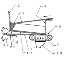
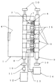
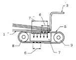
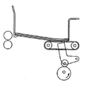
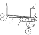
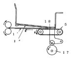
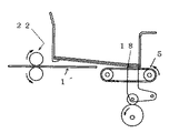
図1は、本発明装置の1例の側方断面図、図2はその平面図、図3は図1の部分拡大図、図4は本発明の紙葉抜き出し機構を説明するための、一部を斜視図とした断面図である。 1 is a side sectional view of an example of the apparatus of the present invention, FIG. 2 is a plan view thereof, FIG. 3 is a partially enlarged view of FIG. 1, and FIG. 4 is a diagram for explaining a paper sheet extracting mechanism of the present invention. It is sectional drawing which made the part the perspective view.
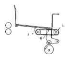
図1において、紙山1は、その前端部をフロントガイド2、後端部をバックゲート3によって支持されている。
このフロントガイド2の下部は、後方側に折り曲げられて受支爪4に形成されている。受支爪4は最下部の紙葉1”が落下しないように受支している。バックゲート3の下端は、フロントガイド2の下端よりも低く配置され、これによって紙山1の後端部は前端部よりも低く保たれている。
In FIG. 1, a
A lower portion of the
紙葉1´の後端部は、複数の(本列の場合4本)吸引ベルト5の上面で支えられ、この吸引ベルト5には吸引孔6,…が穿設されている。吸引ベルト5の下方には吸引孔7´を設けた吸引ボックス7が付設され、これにより紙山1及び吸引ベルト5の重さが支えられている。吸引ベルト5は駆動プーリ8及び従動プーリ9の回転に従って前方向あるいは後方向へ進行する。
The rear end of the
また、吸引ベルト5は無端歯付ベルトを使用し、駆動プーリ8及び従動プーリ9表面の歯と噛合い、駆動プーリ8と吸引ベルト5の間のスリップを防止している。駆動プーリ8は軸受10に回転自在に軸架され、カップリング11を介してサーボモータ12に連結されている。
The
吸引ボックス7は、ダクト13を介しサクションブロア14に連結され、吸引ボックス7内部を負圧に保っている。このため、最下層の紙葉1´は吸引ベルト5の吸引孔により吸引ベルト5に吸着されている。
The
昇降テーブル15,…は吸引ベルト7の間に複数個(本例の場合3個)設けられている。この昇降テーブル15,…は、図4に示すように、支点16を中心としてカム17の回転に対応して昇降テーブル15の上面18が吸引ベルト上面より高くなったり、低くなったりする昇降動作を繰返す。昇降テーブル15の下部はカムフロア19が装着されカム17と転動接触している。
カム17は駆動軸20を介して所定の速度で一方向に連続回転するモータ21により回転駆動されている。
A plurality of lift tables 15,... Are provided between the suction belts 7 (three in this example). As shown in FIG. 4, the elevating table 15,... Performs an elevating operation in which the upper surface 18 of the elevating table 15 becomes higher or lower than the upper surface of the suction belt corresponding to the rotation of the
The
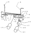
図5ないし図9は、本発明装置の作用を説明するための側面図である。
図5において、サクションブロア14を作動させ、ダクト13、吸引ボックス7、吸引ベルト5の吸引孔6,…を介して、最下層の紙葉を吸引ベルト5に吸着する。吸引ベルト5の吸引孔6,…はベルト全周の内の一部分にのみ設けてあり、(本例では2か所)吸引孔のある部分のみ紙葉を吸着している。
5 to 9 are side views for explaining the operation of the device of the present invention.
In FIG. 5, the suction blower 14 is operated to adsorb the lowermost sheet to the
次に、図6において、サーボモータ12により駆動プーリ8を回転させ、吸引ベルト5を矢印a方向へ移動させ、吸着された紙葉1´を後方(図では右方向)に後退させる。この紙葉1´の前端部は受支爪4の係止を外れてアンダーガイド板23上へ落下し、後端部はバックゲート3と吸引ベルト5との隙間から所定距離だけ後退するとサーボモータ12を停止させ、紙葉1´の後退を停止させる。このとき、昇降テーブル15の上面は吸引ベルト5の上面より低い位置にある。
Next, in FIG. 6, the
また、図7において、サーボモータ12により吸引ベルト5を反対方向、すなわち矢印b方向へ移動させ、吸着された紙葉1´を前方(図では左方向)に前進させる。所定寸法前進すると、昇降テーブル15の上面がカム17の回転に対応して上昇し、吸引ベルト5の上面より高くなり、最下層から二番目の紙葉1”がそれより上層の紙山の重さにより下降し、吸引ベルトに接触しないように二番目の紙葉1”及び上層のシートの重さを支える。吸引ベルト5の吸引孔6,…は最下層の紙葉1´のみを吸引しつつ移動するため、二番目の紙葉1”はこの時点では未だ吸引されない。
In FIG. 7, the
次いで、図8において、吸引ベルト5は前進を続け、昇降テーブル15は上昇状態を保持しつつ、紙葉1´前端がフィードロール22に到達し、フィードロール22に狭持される(フィードロール22も紙葉の前進方向に常時回転している)。紙葉1´の後端が吸引ベルト5の係合から離れると、昇降テーブル15,…の上面は二番目の紙葉1”が未だ走行中の吸引ベルト5に接触しないように所定寸法分、吸引ベルト5の上面より高い位置を保持したまま、その位置を保持している。
Next, in FIG. 8, the
最後に図9において、吸引ベルト5の吸引孔6(2か所の吸引孔の内の他の1か所)の位置が所定位置、すなわち紙葉1”の後端部の下部まで進むと、サーボモータ21が停止し、吸引ベルト5も停止する。吸引ベルト5が停止したのち、昇降テーブル15が下降し、二番目の紙葉1”が吸引ベルト5に吸着され、図5の状態となる。
このような動作を繰り返し、紙山は最下層の紙葉から1枚ずつ順次フィードロール側へ送り出される。
Finally, in FIG. 9, when the position of the suction hole 6 (the other one of the two suction holes) of the
Such an operation is repeated, and the paper pile is sequentially fed out from the lowermost sheet to the feed roll one by one.
本発明は、印刷装置や型打ち抜き装置に紙山の下面から1枚ずつ紙葉を給紙する場合に好適に用いられる。 The present invention is preferably used when a sheet of paper is fed one by one from the lower surface of a paper pile to a printing device or a die punching device.
1 紙山
1´,1” 紙葉
2 フロントガイド
3 バックゲート
4 受支爪
5 吸引ベルト
6 吸引ベルトの吸引孔
7 吸引ボックス
7´吸引ボックスの吸引孔
8 駆動プーリ
9 従動プーリ
10 軸受
11 カップリング
12 サーボモータ
13 ダクト
14 サクションブロア
15 昇降テーブル
16 支点
17 カム
18 上面
19 カムフロア
20 駆動軸
21 モータ
22 フィードロール
23 アンダーガイド板
DESCRIPTION OF
Claims (2)
A suction belt that can be rotated forward and backward, with a front guide that has a nail formed by bending its lower end inward and a back gate, and is arranged in parallel with the back gate to allow only one sheet to pass from the lower end of the back gate. And a lift table for pushing up the paper pile to release contact with the suction belt, and a cam mechanism for raising and lowering it, and a roll for receiving the paper sheet conveyed from the suction belt A paper sheet supply device, wherein the pair is disposed on an upper surface extension of the suction belt.
Priority Applications (4)
| Application Number | Priority Date | Filing Date | Title |
|---|---|---|---|
| JP2004112555A JP2005298078A (en) | 2004-04-06 | 2004-04-06 | Paper sheet feeding method and device |
| CNB2005100599714A CN100448764C (en) | 2004-04-06 | 2005-04-04 | Paper feeding method and apparatus |
| DE602005021425T DE602005021425D1 (en) | 2004-04-06 | 2005-04-05 | Method and device for feeding paper |
| EP05007463A EP1584583B1 (en) | 2004-04-06 | 2005-04-05 | Paper feeding method and apparatus |
Applications Claiming Priority (1)
| Application Number | Priority Date | Filing Date | Title |
|---|---|---|---|
| JP2004112555A JP2005298078A (en) | 2004-04-06 | 2004-04-06 | Paper sheet feeding method and device |
Publications (1)
| Publication Number | Publication Date |
|---|---|
| JP2005298078A true JP2005298078A (en) | 2005-10-27 |
Family
ID=34909493
Family Applications (1)
| Application Number | Title | Priority Date | Filing Date |
|---|---|---|---|
| JP2004112555A Pending JP2005298078A (en) | 2004-04-06 | 2004-04-06 | Paper sheet feeding method and device |
Country Status (4)
| Country | Link |
|---|---|
| EP (1) | EP1584583B1 (en) |
| JP (1) | JP2005298078A (en) |
| CN (1) | CN100448764C (en) |
| DE (1) | DE602005021425D1 (en) |
Cited By (1)
| Publication number | Priority date | Publication date | Assignee | Title |
|---|---|---|---|---|
| JP2007217174A (en) * | 2006-02-20 | 2007-08-30 | Sanwa Seisaku Kk | Paper sheet feeding method and improvement of device |
Families Citing this family (14)
| Publication number | Priority date | Publication date | Assignee | Title |
|---|---|---|---|---|
| JP4886075B1 (en) * | 2011-01-31 | 2012-02-29 | 江沢事務器株式会社 | Cut paper feeding device |
| CN102730440A (en) * | 2011-04-12 | 2012-10-17 | 常州戈顿科技有限公司 | Paper feeding mechanism of paper board processing machinery |
| WO2012170474A1 (en) * | 2011-06-07 | 2012-12-13 | Ranpak Corp. | Reduced footprint dunnage conversion system and method |
| DE102012013517A1 (en) * | 2012-07-06 | 2014-01-09 | Giesecke & Devrient Gmbh | Device and method for separating value documents, as well as value document processing system |
| CN103287615B (en) * | 2013-06-14 | 2016-01-20 | 江西创一精密机械有限公司 | Thin flitch board separating device |
| CN103693465B (en) * | 2013-12-04 | 2018-01-12 | 无锡佳泰科技有限公司 | A kind of improved structure of label paper distribution device |
| DE102015217170B4 (en) * | 2014-09-17 | 2023-10-05 | Heidelberger Druckmaschinen Ag | Device for combining an auxiliary stack with a main stack |
| CN104772928B (en) * | 2015-04-16 | 2017-08-22 | 温州中科包装机械有限公司 | Packing box paper top paper splitting mechanism |
| CN108137250B (en) * | 2015-10-09 | 2019-10-08 | 户谷技研工业株式会社 | Sheet product supply device |
| CN105984737B (en) * | 2015-12-11 | 2018-02-13 | 北京航天斯达科技有限公司 | Paper device for separating single piece in a pile |
| CN106276338B (en) * | 2016-08-23 | 2017-12-05 | 广东东方精工科技股份有限公司 | Paper feeding method that is a kind of while declining timesharing rising lift plate |
| CN110497648A (en) * | 2019-08-16 | 2019-11-26 | 吉文献 | Carton pre-treatment cardboard feed device based on cam return principle |
| CN112249743B (en) * | 2020-12-16 | 2021-06-08 | 佛山市金页盈信智能机械有限公司 | Paper delivery device |
| JP7133261B1 (en) * | 2022-04-12 | 2022-09-08 | 昌弘 塚崎 | Paper feeder and paper feed method |
Family Cites Families (11)
| Publication number | Priority date | Publication date | Assignee | Title |
|---|---|---|---|---|
| US3405935A (en) * | 1966-12-30 | 1968-10-15 | Soroban Engineering Inc | Card picker mechanism |
| GB1409607A (en) * | 1972-10-19 | 1975-10-08 | Rotaprint Gmbh | Sheet take-off device for printing or duplicating machines |
| JPS6050602B2 (en) | 1978-06-14 | 1985-11-09 | 日本板硝子株式会社 | Jig for adhering and fixing molding around the glass plate |
| US4363478A (en) * | 1979-07-23 | 1982-12-14 | Yasuhiro Tsukasaki | Method and apparatus of feeding corrugated boards |
| JPS61114937A (en) | 1984-11-12 | 1986-06-02 | Asahi Tekkosho:Kk | Feeding method of stacked sheets and bottom feeder |
| US5184811A (en) * | 1988-10-13 | 1993-02-09 | Sun Automation, Inc. | Method and apparatus for feeding sheets |
| US5116040A (en) * | 1990-04-06 | 1992-05-26 | De La Rue Giori S.A. | Sheet-feeder |
| FR2708579B1 (en) * | 1993-08-05 | 1995-10-13 | Martin Sa | Method for introducing a material into a plate into a machine for transforming this material into a plate and device for implementing this method. |
| DE19549675B4 (en) * | 1995-07-07 | 2005-02-17 | Windmöller & Hölscher Kg | Method for separating stacked flat tube pieces |
| JPH09194058A (en) * | 1996-01-19 | 1997-07-29 | Asahi Mach Kk | Bottom feeder |
| DE19821871A1 (en) * | 1998-05-15 | 1999-11-18 | Giesecke & Devrient Gmbh | Bank note counting machine with tray advancing towards counter |
-
2004
- 2004-04-06 JP JP2004112555A patent/JP2005298078A/en active Pending
-
2005
- 2005-04-04 CN CNB2005100599714A patent/CN100448764C/en not_active Expired - Fee Related
- 2005-04-05 DE DE602005021425T patent/DE602005021425D1/en not_active Expired - Lifetime
- 2005-04-05 EP EP05007463A patent/EP1584583B1/en not_active Expired - Lifetime
Cited By (1)
| Publication number | Priority date | Publication date | Assignee | Title |
|---|---|---|---|---|
| JP2007217174A (en) * | 2006-02-20 | 2007-08-30 | Sanwa Seisaku Kk | Paper sheet feeding method and improvement of device |
Also Published As
| Publication number | Publication date |
|---|---|
| EP1584583B1 (en) | 2010-05-26 |
| EP1584583A3 (en) | 2008-07-30 |
| CN100448764C (en) | 2009-01-07 |
| EP1584583A2 (en) | 2005-10-12 |
| DE602005021425D1 (en) | 2010-07-08 |
| CN1683225A (en) | 2005-10-19 |
Similar Documents
| Publication | Publication Date | Title |
|---|---|---|
| JP2005298078A (en) | Paper sheet feeding method and device | |
| WO2015050021A1 (en) | Paper feeding device and paper feeding method | |
| JP5495024B2 (en) | Paper feeding device and image forming apparatus | |
| JP2827429B2 (en) | Suction paper feeder | |
| EP0022210A1 (en) | Sheet feeding and stacking device and method | |
| JPH072536B2 (en) | Bottom sheet separating / feeding device | |
| JP2021059417A (en) | Conveying device | |
| JP2011190022A (en) | Paper feeder | |
| JPS61254438A (en) | Sheet feeder | |
| WO2022007412A1 (en) | Intermittent card feeding mechanism and method, and card sending device | |
| JP2005178946A (en) | Paper feeding device | |
| JP2007331905A (en) | Paper feeder, its control method, and printer using this | |
| US7513494B2 (en) | Method and device for selecting the sheets of a record carrier from a pile | |
| JP3620198B2 (en) | Paper sheet separator | |
| JPH09194058A (en) | Bottom feeder | |
| JP2008179424A (en) | Paper feeding device | |
| WO1993015010A1 (en) | Device for conveying and stacking paper sheets | |
| JP6633933B2 (en) | Feeder | |
| JP2673286B2 (en) | Paper stack transport stack device | |
| JP2005320158A (en) | Separation method and device for sheets of recording media in a pile | |
| JP3713459B2 (en) | Paper sheet processing equipment | |
| CN112499348B (en) | Sheet feeding device and image forming apparatus | |
| JP2009073659A (en) | Paper feeder | |
| JP2000007232A (en) | Sheet storage and delivery device | |
| JP2001151371A5 (en) |