JP2005298047A - Rotary type timer filling apparatus - Google Patents
Rotary type timer filling apparatus Download PDFInfo
- Publication number
- JP2005298047A JP2005298047A JP2004120497A JP2004120497A JP2005298047A JP 2005298047 A JP2005298047 A JP 2005298047A JP 2004120497 A JP2004120497 A JP 2004120497A JP 2004120497 A JP2004120497 A JP 2004120497A JP 2005298047 A JP2005298047 A JP 2005298047A
- Authority
- JP
- Japan
- Prior art keywords
- valve
- cam
- opening
- closing
- timer
- Prior art date
- Legal status (The legal status is an assumption and is not a legal conclusion. Google has not performed a legal analysis and makes no representation as to the accuracy of the status listed.)
- Pending
Links
- 238000011144 upstream manufacturing Methods 0.000 claims abstract description 3
- 239000012530 fluid Substances 0.000 claims description 23
- 239000007788 liquid Substances 0.000 abstract description 74
- 230000002093 peripheral effect Effects 0.000 description 6
- 238000002347 injection Methods 0.000 description 4
- 239000007924 injection Substances 0.000 description 4
- 238000001514 detection method Methods 0.000 description 3
- 230000000903 blocking effect Effects 0.000 description 2
- 238000000034 method Methods 0.000 description 2
- 238000010586 diagram Methods 0.000 description 1
Images
Landscapes
- Filling Of Jars Or Cans And Processes For Cleaning And Sealing Jars (AREA)
Abstract
Description
本発明は、タイマーにより充填時間を計測して充填を行うタイマー充填装置に係り、特に、ロータリー式のタイマー充填装置に関するものである。 The present invention relates to a timer filling device that performs filling by measuring a filling time with a timer, and more particularly to a rotary timer filling device.
液バルブを開放して充填を開始し、この充填時間をタイマーによって計測する。そして、所定時間経過したときに液バルブを閉じることにより、所定量の充填液を容器内に充填するようにしたタイマー式充填装置は従来から広く知られている。 The liquid valve is opened to start filling, and this filling time is measured by a timer. A timer-type filling device that fills a container with a predetermined amount of filling liquid by closing a liquid valve when a predetermined time has elapsed has been widely known.
前記液バルブの開閉を行う開閉手段として、固定のカムを用いると、構造が簡単でローコストであるが、ロータリー式の充填装置の場合には、連続運転を行っており、その連続運転中に運転速度が変動すると、液バルブの開放時間が変化して充填量が一定にならないという問題が発生する。 If a fixed cam is used as the opening and closing means for opening and closing the liquid valve, the structure is simple and low cost, but in the case of a rotary filling device, continuous operation is performed, and operation is performed during the continuous operation. When the speed fluctuates, there arises a problem that the opening time of the liquid valve changes and the filling amount does not become constant.
ロータリー式充填装置で運転速度が変動しても液バルブの開放時間を一定にするためには、電磁弁を用いて、個々の液バルブの開閉をタイマーで制御すればよいが、電磁弁は高価であり、また、ロータリーコネクタやスリップリング等の電気的な回転継手が必要となりコストアップになってしまう。 In order to make the opening time of the liquid valve constant even if the operating speed fluctuates in the rotary filling device, it is sufficient to use a solenoid valve to control the opening and closing of each liquid valve with a timer, but the solenoid valve is expensive. In addition, an electrical rotary joint such as a rotary connector or slip ring is required, resulting in an increase in cost.
ロータリー式の充填装置において、カムを用いてバルブの開放時間をできるだけ一定にする技術がすでに知られている(例えば、特許文献1参照)。この特許文献1に記載された充填装置は、容器内に充填された余剰の充填液をガス通路から外部に排出して容器内の充填液の液面高さを一定にするトッピングバルブを、カムに係合させて開放するもので、4つのカムを前記トッピングバルブに係合する位置と係合しない位置とに移動可能に設け、それぞれソレノイドにより進退動できるようにしたものであり、これらソレノイドを、充填装置の運転速度を検出するセンサからの信号によりオンオフ制御することにより、トッピングバルブの開放時間を一定にしようとしている。
前記特許文献1に記載された充填装置の問題点は、運転速度に応じて4つのカムのうちトッピングバルブに係合するカムの数を変更するもので、運転速度に比例してトッピングバルブの開放距離を変動させることはできず、一定の速度範囲では同一の区間トッピングバルブを開放することになるという段階的制御を行っており、トッピングバルブの開放時間を完全に一定にすることは不可能である。
The problem with the filling device described in
本発明のロータリー式タイマー充填装置は、回転体に設けられ、この回転体の外部に配置された開放用カムに係合して流体バルブを開放するバルブ開閉手段と、前記開放用カムの下流側に設けられ、前記バルブ開閉手段に係合して流体バルブを閉鎖する閉鎖用カムと、前記流体バルブの開放時間を計測するタイマーと、前記回転体の回転速度を検出する検出手段とを備え、前記閉鎖用カムを複数のカムから構成し、これらカムのうち少なくとも一つを前記バルブ開閉手段と係合する位置と係合しない位置とに進退動可能にし、前記回転体の回転速度が低下した際には、タイマーが所定の開放時間を計測した時点で、進退動可能なカムを前進させて流体バルブを閉鎖することを特徴とするものである。 The rotary timer filling device of the present invention includes a valve opening / closing means that is provided in a rotating body and engages with an opening cam disposed outside the rotating body to open a fluid valve, and a downstream side of the opening cam. A closing cam for closing the fluid valve by engaging with the valve opening and closing means, a timer for measuring the opening time of the fluid valve, and a detecting means for detecting the rotational speed of the rotating body, The closing cam is composed of a plurality of cams, and at least one of the cams can be moved back and forth between a position engaging with the valve opening / closing means and a position not engaging, and the rotational speed of the rotating body is reduced. In this case, when the timer measures a predetermined opening time, the fluid valve is closed by advancing the cam that can move forward and backward.
また、請求項2に記載の発明は、回転体に設けられ、この回転体の外部に配置された開放用カムに係合して流体バルブを開放するバルブ開閉手段と、前記開放用カムの下流側に設けられ、前記バルブ開閉手段に係合して流体バルブを閉鎖する閉鎖用カムと、前記流体バルブの開放時間を計測するタイマーと、前記バルブ開閉手段の位置を検出する検出手段とを備え、前記閉鎖用カムを複数のカムから構成し、これらカムのうち少なくとも一つを前記バルブ開閉手段と係合する位置と係合しない位置とに進退動可能にし、前記バルブ開閉手段が開放用カムに係合してからタイマーが所定の開放時間を計測した時点で、当該開閉バルブに対応する位置にある進退動可能なカムを前進させて流体バルブを閉鎖することを特徴とするものである。 According to a second aspect of the present invention, there is provided a valve opening / closing means provided on the rotating body and engaged with an opening cam disposed outside the rotating body to open the fluid valve, and downstream of the opening cam. A closing cam that is provided on the side and that engages with the valve opening / closing means to close the fluid valve, a timer that measures the opening time of the fluid valve, and a detection means that detects the position of the valve opening / closing means. The closing cam is composed of a plurality of cams, and at least one of the cams can be moved back and forth between a position engaging with the valve opening / closing means and a position not engaging with the valve opening / closing means. When the timer measures a predetermined opening time after the engagement, the fluid valve is closed by advancing the cam that can be moved forward and backward at the position corresponding to the opening / closing valve.
本発明のロータリー式タイマー充填装置は、カムを用いた構成でありながら流体バルブの開放時間を正確に制御し、充填量を一定にすることが可能である。従って、電磁弁や電気的な回転継手等の高価な部品が必要ないので、構造が簡単でローコストな構成にすることができる。 The rotary timer filling device of the present invention is configured to use a cam, but can accurately control the opening time of the fluid valve to make the filling amount constant. Therefore, since expensive parts such as a solenoid valve and an electric rotary joint are not required, the structure can be simplified and the structure can be made low-cost.
本発明は、回転体に設けられたバルブ開閉手段を開閉用カムに係合させて流体バルブを開放し、タイマーで流体バルブ開放後所定時間経過したことをカウントしたら、そのバルブ開閉手段を閉鎖用カムに係合させることにより、前記流体バルブを閉じて充填を終了するようにしている。そして、閉鎖用カムを複数のカムから構成し、いずれかのカムをバルブ開閉手段に係合する位置と係合しない位置とに進退動できるようにしておき、回転体の回転速度が遅くなったときには、充填時間経過時のバルブ開閉手段の位置に対応するカムを係合位置に移動させて充填を終了させるという簡単な構成で、ローコストなロータリー式タイマー充填装置を得るという目的を達成する。 In the present invention, the valve opening / closing means provided on the rotating body is engaged with the opening / closing cam to open the fluid valve, and when the timer counts that a predetermined time has passed after the fluid valve is opened, the valve opening / closing means is closed. By engaging with the cam, the fluid valve is closed to finish the filling. Then, the closing cam is composed of a plurality of cams, and any one of the cams can be moved forward and backward to a position where the cam is engaged with the valve opening / closing means and a position where the cam is not engaged. In some cases, the objective of obtaining a low-cost rotary timer filling device is achieved with a simple configuration in which the cam corresponding to the position of the valve opening / closing means when the filling time has elapsed is moved to the engagement position to end the filling.
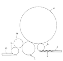
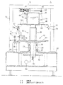
以下、図面に示す実施例により本発明を説明する。図1は本発明の一実施例に係るロータリー式タイマー充填装置を備えた充填システムの全体の構成を簡略化して示す平面図、図2は前記ロータリー式タイマー充填装置と排出スターホイールとが一体となった第2充填機(全体として符号1で示す)の縦断面図である。
Hereinafter, the present invention will be described with reference to embodiments shown in the drawings. FIG. 1 is a plan view schematically showing the entire configuration of a filling system including a rotary timer filling device according to an embodiment of the present invention, and FIG. 2 is a diagram showing that the rotary timer filling device and the discharge star wheel are integrated. It is a longitudinal cross-sectional view of the 2nd filling machine which became (it shows with the code |
この充填システムは、容器供給コンベヤ2によって連続的に搬送されてきた多数の容器4が、この供給コンベヤ2上に設けられているインフィードスクリュー6によって所定の間隔に切り離され、供給スターホイール8を介して第1充填機10内に供給される。この第1充填機10では、供給された容器4が回転搬送される間に、容器4内に充填される所定量の液体のうちの大部分が充填される。第1充填機10での充填が済んだ容器4は、前記第2充填機1の下部に設けられている排出スターホイール12によって取り出されるとともに、この排出スターホイール12の上方に一体的に設けられているロータリー式タイマー充填装置14に供給される。このロータリー式タイマー充填装置14によって、前記第1充填機10で充填された液量の残りの少量の液体が充填される。所定量の充填液全量の充填が行われた容器4は、この第2充填機10に隣接して配置されているキャッパ16に導入され、キャッピングが行われた後、排出スターホイール18を介して排出コンベヤ20上に排出されて次の工程に送られる。
In this filling system, a large number of
次に、前記ロータリー式タイマー充填装置14と、このロータリー式タイマー充填装置14の下方に一体に設けられた排出スターホイール12とを有する第2充填機1の構成について、図2により説明する。なお、ロータリー式タイマー充填装置14は必ずしも排出スターホイール12に組み込む必要はなく、独立して設置することもできる。
Next, the configuration of the
排出スターホイール12は、ベース22の中央部に直立して取り付けられた固定筒体24と、この固定筒体24の内部にボールベアリング28を介して回転自在に支持された中空の回転軸26と、この中空回転軸26の上端に固定された回転ホイール30とを備えている。さらに、この回転ホイール30の外周には、容器4を受け入れる凹部(図示せず)が円周方向等間隔で設けられた保持ガイド(下部保持ガイド)32と、この下部保持ガイド32の上方に、同様にして容器4を受け入れる凹部が形成された上部保持ガイド34が取り付けられている。これら中空の回転軸26、回転ホイール30および後に説明するロータリー充填装置14の回転部等からなる回転体35は、回転軸26の下端に取り付けられた回転ギヤ36が、図示しない駆動ギヤに噛み合って回転を伝達されることにより回転するようになっている。
The
前記回転ホイール30の外周側の、回転ホイール30の高さよりもやや低い位置に、この回転ホイール30と同心の円弧状をした支持プレート38が配設されている。この支持プレート38は、前記ベース22上に支柱40を介して固定されており、前記回転ホイール30の上下保持ガイド32、34に保持されて搬送される容器4の底面を支持するようになっている。また、この円弧状支持プレート38の上面の外周側に、前記回転ホイール30に取り付けられている上下の保持ガイド34、32と対向するようにして、搬送される容器4の外周側を案内する上下の外周ガイド42、44が固定されている。前記回転ホイール30、上下の保持ガイド32、34、下方の支持プレート38および上下の外周ガイド42、44等によって、従来から一般に用いられている排出スターホイール12が構成されている。
A
前記回転ホイール30の中央部上方に、円筒形の中心軸46が直立して固定され、この中心軸46上に、ロータリー式タイマー充填装置14の充填液タンク48が取り付けられており、この充填液タンク48が前記回転軸26および回転ホイール30と一体的に回転する。これら充填液タンク48、中心軸46、回転ホイール30および回転軸26が回転体を構成している。充填液タンク48の下端外周部には、前記容器保持ガイド32、34に設けられた容器4保持用の各凹部に対応して、注液パイプ50が取り付けられている。これら各注液パイプ50の先端には、それぞれ液バルブ52を介して充填ノズル54が取り付けられており、この液バルブ52を開閉することによって、注液パイプ50から充填ノズル54に通じる充填液の通路を連通、遮断して、容器4内への液体の充填を行うようになっている。
A cylindrical
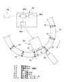
充填液タンク48の上部外周にフランジ56が形成され、このフランジ56上に、複数本のステー58を介してリング状プレート60が取り付けられている。このリング状プレート60には、図3に示すように、円周方向等間隔で前記液バルブ52の数と同数のメカバルブ(液バルブ開閉手段)62が取り付けられている。このメカバルブ62は、自己保持機能付きであり、後に説明するカムによって下流側の液バルブ52にエアを供給する位置と、供給しない位置とに切り換えるようになっている。
A
前記中空の回転軸26の底部にロータリーフィッティング64が取り付けられており、図示しないエア供給手段からこのロータリーフィッティング64を介して前記各メカバルブ62にエアが供給される。ロータリーフィッティング64を介して前記メカバルブ62に供給されたエアは、メカバルブ62がエア供給位置に切り換えられているときには、このメカバルブ62を通って前記液バルブ52に送られる。
A
この液バルブ52は、従来周知の構成でありその内部構造の図示は省略するが、ベローズ式であり、スプリングによって付勢されたピストンによりベローズを押圧し、または、エア室に導入したエアによってピストンを後退させることにより、前記充填液タンク48に接続された注液パイプ50から充填ノズル54への充填液通路を開閉するようになっている。前記メカバルブ62をエア供給位置に切り換えると、この液バルブ52のエア室にエアが導入されてピストンが後退し、充填液通路が開放して充填が行われる。一方、前記メカバルブ62をエアを供給しない位置に切り換えて、液バルブ52へのエアの供給を遮断すると、ピストンがスプリングに押されてベローズが前記充填液通路を閉じるようになっている。
The
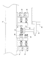
前記メカバルブ62は、このメカバルブ62が取り付けられているリング状プレート60の外周側に配置された開放用カム66に係合して開放され、この開放用カム66よりも下流側の、リング状プレート60の内周側に配置された閉鎖用カム(全体として符号68で示す)に係合して閉鎖されるようになっている。これら開放用カム66および閉鎖用カム68は、この第2充填機1が収容されている機枠70の天板72の下面側に固定されている。この実施例では、メカバルブ62が、リング状プレート60の上面側と下面側に交互に取り付けられている。これは、前記開放用カム66および閉鎖用カム68と係合する際のピッチを広くするためであり、必ずしもリング状プレート60の上面側と下面側とに交互に配置する必要はない。従って、開放用カム66および閉鎖用カム68は、上下2つの高さのメカバルブ62に係合するように、それぞれ上下2つが一組となって配置されている。
The
開放用カム66は、エアシリンダ74によって半径方向内方に向かって進退動できるようになっており、前進しているときには、回転移動してきた前記メカバルブ62が係合して開放し、前記液バルブ52にエアを供給する。また、開放用カム66が後退したときには、メカバルブ62と係合しないようになっている。この開放用カム66は、各メカバルブ62に対応する液バルブ52および充填ノズル54の位置に容器4が供給されているときには、前進した位置でメカバルブ62に係合して開放し、容器4が供給されないときだけ後退して、メカバルブ62を開放せず、充填ノズル54から充填液を吐出しないようにしている。
The
閉鎖用カム68は複数のカムからなっており、この実施例では、最も下流側に固定カム76が配置され、その上流側に第1可動カム78および第2可動カム80が順に設けられている。固定カム76は、前記開放用カム66によって開放されているメカバルブ62が移動してきたときに係合して閉鎖する。また、第1および第2の可動カム78、80は、エアシリンダ82(第2可動カム80のシリンダは図示せず)によって半径方向外方に向かって進退動できるようになっており、前進しているときには、開放しているメカバルブ62が係合して閉じ、後退しているときには、メカバルブ62が係合しないようになっている。
The
このロータリ式タイマー充填装置14は、前記メカバルブ62の位置および回転体35の回転速度を検出するためのエンコーダ84と、このエンコーダ84からの信号が入力される制御装置86とを備えている。制御装置86は、液バルブ52の開放時間をカウントするタイマー86A、前記エンコーダ84とタイマー86Aからの信号が入力され、前記可動カム78、80の作動タイミングを演算するタイミング演算部86Bおよび可動カム78、80に作動指令を出力する指令部86Cを有している。前記メカバルブ62の移動位置は、エンコーダ84からの信号により検出される。また、回転体35の回転速度は、エンコーダ84とタイマー86Aにより、単位時間あたりどれだけのパルス数をカウントするかによって算出される。
The rotary
以上の構成に係るロータリー式タイマー充填装置14の作動について説明する。容器供給コンベヤ2によって搬送されてきた容器4は、タイミングスクリュー6によって所定の間隔に切り離され、供給スターホイール8を介して第1充填機10内に供給される。第1充填機10内で回転搬送される間に、容器4内に所定量の充填液が充填される。この実施例の充填システムでは、第1充填機10で所定の充填量のほとんど全量を充填し、次の第2充填機1のロータリー式タイマー充填装置14によって残りのごく少量の液体を充填するようになっている。例えば、容器4内に充填される全充填液量が1800ccの場合に、第1充填機10で1795ccの液体を充填し、残りの5ccをロータリー式タイマー充填装置14によって充填する。
The operation of the rotary
第1充填機10で規定量の液体が充填された容器4は、このロータリー式タイマー充填装置14と一体に設けられている排出スターホイール12によって、前記第1充填機10から取り出される。この排出スターホイール12とその上方に設けられているロータリー式タイマー充填装置14からなる第2充填機1は、中空の回転軸26の回転により一体的に回転するようになっており、排出スターホイール12の回転ホイール30に取り付けられている上下の保持ガイド32、34に保持された容器4の口部上方に、充填ノズル54が位置している。この充填ノズル54への液通路を開閉する液バルブ52は、上方のメカバルブ62から供給されるエアによって開閉するようになっており、前記メカバルブ62が回転移動して開放用カム66の位置に到達すると、この開放用カム66に係合してメカバルブ62が開放し、外部のエア供給源からロータリーフィッティング64を介して送られたエアが、このメカバルブ62を通って液バルブ52に供給され、この液バルブ52が開放する。液バルブ52が開放すると、充填液タンク48内の充填液が、注液パイプ50および充填ノズル54を通って容器4内に充填される。
The
前記制御装置86のタイミング演算部86Bでは、エンコーダ84からの信号により、前記メカバルブ62が開放用カム66に係合したことを認識し、その時点よりタイマー86Aからの信号をカウントする。前記メカバルブ62の開放した時点からの経過時間を前記タイマー86Aによってカウントし、所定の充填時間を経過するとメカバルブ62を切り換えて液バルブ52を閉じるようになっている。タイマー86Aからの信号が所定時間カウントされた時点で、メカバルブ62の位置を検出し、メカバルブ62が固定カム76の位置に到達していれば、この固定カム76によってメカバルブ62が切り換えられ、下方の液バルブ52に送られていたエアが停止して液バルブ52が閉じ、充填が終了する。従って、このときには制御装置86からの可動カム78、80への前進指令は出力されない。
The
また、タイマー86Aからの信号が所定時間カウントされた時点で、メカバルブ62が固定カム76の位置に到達していない場合には、エンコーダ84からの信号によりメカバルブ62の位置を検出し、制御装置86は、そのメカバルブ62の位置に対応するいずれか一方の可動カム78、80を前進させる。メカバルブ62は、この前進された可動カム78または80に係合して切り換えられ、液バルブ52へのエアの供給を停止して液バルブ52を閉鎖する。以上のようにこの実施例に係る充填装置では、電磁弁やロータリージョイント等の高価な部品を使用せず、所定の時間が経過した時点で閉鎖用カム68によって液バルブ52を閉じることができるので、極めて簡単な構成でローコストな充填装置を得ることができる。しかも、極めてわずかな量の液体を充填する場合でも、正確に充填することができる。さらに、前記エンコーダ84およびタイマー86Aの信号によって第2充填機1の回転速度を検出し、回転速度が遅くなった場合に、エンコーダ84からの信号によりメカバルブ62の位置を検出し、このメカバルブ62に対応する位置の可動カム78、80を前進させるようにしても良い。つまり、回転体35の回転速度とメカバルブ62の位置の両方を検出して、適切な可動カム78、80を選択し作動させるようにしても良い。
If the
前記実施例では、エンコーダ84によってメカバルブ62の位置を検出し、このメカバルブ62の位置に対応する閉鎖用カム68(固定カム76および可動カム78、80)のいずれかによってメカバルブ62を切り換えるようにしているが、回転体35の回転速度を検出し、この回転速度からメカバルブ62の位置を演算して、この位置に対応する可動カム78、80を前進させてメカバルブ62を切換え、または、可動カム78、80を前進させず、固定カム76によってメカバルブ62を切り換えるようにすることもできる。
In the above embodiment, the position of the
第2充填機1が通常の運転速度で回転している場合には、タイマー86Aにより所定時間カウントされた時点で、メカバルブ62が閉鎖用カム68のうちの最も下流側に位置している固定カム76の位置に到達しており、この固定カム76に係合してメカバルブ62が切り換えられ、下方の液バルブ52に送られていたエアが停止して液バルブ52が閉じ、充填が終了する。
When the
また、第2充填機1の回転速度が遅くなった場合には、メカバルブ62が開放用カム66に係合してエアを供給する位置に切り換えられ、液バルブ52を開放して充填が開始した後、タイマー86Aのカウント時間が所定の充填時間を経過した時点で、メカバルブ62は固定カム76の位置に到達していない。このときには、エンコーダ84およびタイマー86Aからの信号により回転体35の回転速度を検出し、この回転速度からメカバルブ62の位置を演算し、制御装置86は、そのメカバルブ62の位置に対応するいずれか一方の可動カム78、80を前進させる。作動した可動カム78、80によって、メカバルブ62が切り換えられ、液バルブ52が閉じて充填が終了する。
Further, when the rotation speed of the
前記ロータリー式タイマー充填装置14での充填が終了した容器4は、次のキャッパ16に送られてキャッピングが行われた後、排出スターホイール18を介して排出コンベヤ20上に排出されて次の工程に送られる。なお、前記実施例では、液体を充填する充填装置について説明したが、液体に限るものではなく、この実施例の構成を気体にも適用可能である。また、エアの通路を開閉するメカバルブ62を充填液タンク48の上方に、一方、前記メカバルブ62からのエアの供給、停止によって充填液通路を連通、遮断する液バルブ52を充填液タンク48の下方に配置したが、必ずしも別体にする必要はなく、一体の構成とすることもできる。また、閉鎖用の可動カムの数は2個に限るものではなく、1個あるいは3個以上であっても良い。さらに、閉鎖用カム68に固定カムを設けず、全てを可動カムとして、メカバルブ62の位置に応じていずれか一つの可動カムを前進させるようにしても良い。
The
35 回転体
52 流体バルブ(液バルブ)
66 開放用カム
68 閉鎖用カム(全体)
76 固定カム
78 第1可動カム
80 第2可動カム
84 検出手段(エンコーダ)
86A 検出手段(タイマー)
35
66 Cam for opening 68 Cam for closing (entire)
76 fixed
86A Detection means (timer)
Claims (4)
前記閉鎖用カムを複数のカムから構成し、これらカムのうち少なくとも一つを前記バルブ開閉手段と係合する位置と係合しない位置とに進退動可能にし、前記回転体の回転速度が低下した際には、タイマーが所定の開放時間を計測した時点で、進退動可能なカムを前進させて流体バルブを閉鎖することを特徴とするロータリー式タイマー充填装置。 A valve opening / closing means that is provided on the rotating body and engages with an opening cam disposed outside the rotating body to open the fluid valve; and provided on the downstream side of the opening cam, the valve opening / closing means. A closing cam for closing the fluid valve, a timer for measuring the opening time of the fluid valve, and a detecting means for detecting the rotational speed of the rotating body,
The closing cam is composed of a plurality of cams, and at least one of the cams can be moved back and forth between a position engaging with the valve opening / closing means and a position not engaging, and the rotational speed of the rotating body is reduced. In this case, the rotary timer filling device is characterized in that when the timer measures a predetermined opening time, the fluid valve is closed by advancing the cam that can move forward and backward.
前記閉鎖用カムを複数のカムから構成し、これらカムのうち少なくとも一つを前記バルブ開閉手段と係合する位置と係合しない位置とに進退動可能にし、前記バルブ開閉手段が開放用カムに係合してからタイマーが所定の開放時間を計測した時点で、当該開閉バルブに対応する位置にある進退動可能なカムを前進させて流体バルブを閉鎖することを特徴とするロータリー式タイマー充填装置。 A valve opening / closing means that is provided on the rotating body and engages with an opening cam disposed outside the rotating body to open the fluid valve; and provided on the downstream side of the opening cam, the valve opening / closing means. A closing cam for closing the fluid valve, a timer for measuring the opening time of the fluid valve, and a detecting means for detecting the position of the valve opening and closing means,
The closing cam is composed of a plurality of cams, and at least one of the cams can be moved back and forth between a position engaging with the valve opening / closing means and a position not engaging with the valve opening / closing means. A rotary timer filling device, wherein when a timer measures a predetermined opening time after engagement, a fluid valve is closed by advancing a cam that can move forward and backward at a position corresponding to the opening / closing valve. .
Priority Applications (1)
| Application Number | Priority Date | Filing Date | Title |
|---|---|---|---|
| JP2004120497A JP2005298047A (en) | 2004-04-15 | 2004-04-15 | Rotary type timer filling apparatus |
Applications Claiming Priority (1)
| Application Number | Priority Date | Filing Date | Title |
|---|---|---|---|
| JP2004120497A JP2005298047A (en) | 2004-04-15 | 2004-04-15 | Rotary type timer filling apparatus |
Publications (1)
| Publication Number | Publication Date |
|---|---|
| JP2005298047A true JP2005298047A (en) | 2005-10-27 |
Family
ID=35330071
Family Applications (1)
| Application Number | Title | Priority Date | Filing Date |
|---|---|---|---|
| JP2004120497A Pending JP2005298047A (en) | 2004-04-15 | 2004-04-15 | Rotary type timer filling apparatus |
Country Status (1)
| Country | Link |
|---|---|
| JP (1) | JP2005298047A (en) |
Cited By (2)
| Publication number | Priority date | Publication date | Assignee | Title |
|---|---|---|---|---|
| US9428373B2 (en) | 2011-04-06 | 2016-08-30 | Mitsubishi Heavy Industries Food & Packaging Machine Co., Ltd. | Rotary-type filling machine and method for calculating filling quantity for rotary-type filling machine |
| CN107892036A (en) * | 2017-09-30 | 2018-04-10 | 广州达意隆包装机械股份有限公司 | A kind of station for rotary filling machine hinders bottle control system |
-
2004
- 2004-04-15 JP JP2004120497A patent/JP2005298047A/en active Pending
Cited By (3)
| Publication number | Priority date | Publication date | Assignee | Title |
|---|---|---|---|---|
| US9428373B2 (en) | 2011-04-06 | 2016-08-30 | Mitsubishi Heavy Industries Food & Packaging Machine Co., Ltd. | Rotary-type filling machine and method for calculating filling quantity for rotary-type filling machine |
| CN107892036A (en) * | 2017-09-30 | 2018-04-10 | 广州达意隆包装机械股份有限公司 | A kind of station for rotary filling machine hinders bottle control system |
| CN107892036B (en) * | 2017-09-30 | 2019-08-27 | 广州达意隆包装机械股份有限公司 | A kind of station resistance bottle control system for rotary filling machine |
Similar Documents
| Publication | Publication Date | Title |
|---|---|---|
| US4053003A (en) | Machine for filling containers | |
| US8656688B2 (en) | Capper | |
| EP1801066B1 (en) | System for feeding caps | |
| US10640250B2 (en) | Container-treating machine | |
| EP1566359B1 (en) | Capping head for applying screw caps | |
| CN101679011A (en) | Sectional drive for a slewing ring in a filling installation | |
| ITPR20130017A1 (en) | CLOSING TREATMENT SYSTEM FOR CONTAINERS USING A STERILIZING SUBSTANCE | |
| JP2010001076A (en) | Open jet filling system | |
| JP2002054763A (en) | Magnet valve | |
| JP2001261096A (en) | Apparatus and method for filling container with fluid material to be filled | |
| US6264457B1 (en) | Servo infeed system for transferring preforms in a container manufacturing facility | |
| CN110143559A (en) | A kind of filling integrated apparatus of veterinary drug bottle feeding | |
| KR100876585B1 (en) | Beverage auto injector | |
| US9546083B2 (en) | Filling machine | |
| JP5011783B2 (en) | Rotary filling machine | |
| JP2001114396A (en) | Rotary filling apparatus | |
| JP2008105699A (en) | Filling valve | |
| JP2831170B2 (en) | Valve cleaning device for rotary filling machine | |
| CN212740714U (en) | Filling equipment anchor clamps trouble detection equipment and system | |
| JP4366756B2 (en) | Rotary filling device | |
| US1614485A (en) | Bottle-filling machine | |
| US12129130B2 (en) | Device and method for transporting containers | |
| JP4893987B2 (en) | Filling capping device | |
| US3461923A (en) | Submergible filling head | |
| RU2843743C1 (en) | Method for volumetric dispensing of thick products |
Legal Events
| Date | Code | Title | Description |
|---|---|---|---|
| A621 | Written request for application examination |
Effective date: 20061030 Free format text: JAPANESE INTERMEDIATE CODE: A621 |
|
| A977 | Report on retrieval |
Free format text: JAPANESE INTERMEDIATE CODE: A971007 Effective date: 20090306 |
|
| A131 | Notification of reasons for refusal |
Effective date: 20090414 Free format text: JAPANESE INTERMEDIATE CODE: A131 |
|
| A521 | Written amendment |
Free format text: JAPANESE INTERMEDIATE CODE: A523 Effective date: 20090611 |
|
| A02 | Decision of refusal |
Free format text: JAPANESE INTERMEDIATE CODE: A02 Effective date: 20091020 |