JP2005298037A - Packaging bag and electronic component package using the same - Google Patents
Packaging bag and electronic component package using the same Download PDFInfo
- Publication number
- JP2005298037A JP2005298037A JP2004119910A JP2004119910A JP2005298037A JP 2005298037 A JP2005298037 A JP 2005298037A JP 2004119910 A JP2004119910 A JP 2004119910A JP 2004119910 A JP2004119910 A JP 2004119910A JP 2005298037 A JP2005298037 A JP 2005298037A
- Authority
- JP
- Japan
- Prior art keywords
- film
- layer
- packaging bag
- bag
- clean
- Prior art date
- Legal status (The legal status is an assumption and is not a legal conclusion. Google has not performed a legal analysis and makes no representation as to the accuracy of the status listed.)
- Pending
Links
Images

Landscapes
- Bag Frames (AREA)
- Wrappers (AREA)
- Packaging Frangible Articles (AREA)
- Laminated Bodies (AREA)
Abstract
【課題】 本発明における課題は、アウトイオン、パーティクル、Sn、Si、アウトガスが少ないことが定量的に示され、透明性を有しかつ金属箔並の高い防湿性を有するクリーンフィルムをよりなる包装袋を提供することを目的とする。また、前記包装袋を用いた電子部品包装体を提供することを目的とする。
【課題手段】 クラス1000以下のクリーンルームにおいてLPC(液中パーティクルカウンター)測定したとき、シーラント表面に付着している粒径1μm以上のパーティクル数が1個/cm2以下のクリーンフィルムよりなることを特徴とする包装袋や、前記クリーンフィルムのシーラントの少なくとも片側にガスバリア性フィルムを積層した多層構造を有するクリーンフィルムよりなることを特徴とする包装袋を提供するものである。また、前記包装袋を用いて電子部品を包装したことを特徴とする電子部品包装体を提供するものである。
を提供するものである。
【選択図】 なしPROBLEM TO BE SOLVED: A packaging comprising a clean film that is quantitatively shown to be low in out ions, particles, Sn, Si, and out gas, and has transparency and high moisture resistance equivalent to that of a metal foil. The purpose is to provide a bag. Moreover, it aims at providing the electronic component package using the said packaging bag.
[Means for solving the problem] When a LPC (liquid particle counter) measurement is performed in a clean room of class 1000 or less, the number of particles having a particle diameter of 1 μm or more adhering to the surface of the sealant is 1 / cm 2 or less. And a clean film having a multilayer structure in which a gas barrier film is laminated on at least one side of the sealant of the clean film. In addition, the present invention provides an electronic component packaging body in which an electronic component is packaged using the packaging bag.
Is to provide.
[Selection figure] None
Description
本発明は、塵・埃等の付着、ハロゲンイオンをはじめとする化学物質の付着を極端に嫌うシリコンウエハー、IC、LSI等の半導体製品、コンピューター周辺装置の記憶装置であるFDD、光磁気ディスクドライブ、HDD、MF(磁気抵抗効果式)ヘッド等、メモリ媒体であるFD、HD等の電子部品等の包装分野に関するものである。さらに詳しくは、内容物に接触する可能性があるシーラントフィルム層からの溶出成分、揮発性成分、初塵等が定量的に少なく、かつ高い防湿性と内容物の認識が可能な透明性が必要とされる包装分野に関するものである。 The present invention relates to silicon wafers, IC products, semiconductor products such as ICs, LSIs, FDDs that are storage devices for computer peripheral devices, magneto-optical disk drives, and the like, which are extremely unsuitable for adhesion of dust and other chemical substances such as halogen ions. The present invention relates to the packaging field of electronic components such as FD and HD which are memory media such as HDD, MF (magnetoresistance effect type) heads. More specifically, the amount of elution components, volatile components, initial dust, etc. from the sealant film layer that may come into contact with the contents is quantitatively low, and high moisture resistance and transparency that allows the contents to be recognized are required. It relates to the packaging field.
シリコンウエハー、IC、LSI等の半導体製品、コンピューター周辺装置の記憶装置であるFDD、光磁気ディスクドライブ、HDD、MR(磁気抵抗効果式)ヘッド等、メモリ媒体FDD、HD等の電子部品は極微小、極微量の汚染物で腐食、動作不良等の障害が起こる。 Electronic products such as silicon wafers, ICs, LSIs and other semiconductor products, computer peripheral devices FDD, magneto-optical disk drives, HDDs, MR (magnetoresistance effect) heads, memory media FDD, HD, etc. Failures such as corrosion and malfunction may occur due to extremely small amounts of contaminants.
HDDを例に挙げると上記汚染物質は(1)腐食の原因となるイオン性物質、(2)ヘッド−ディスク間に侵入して記録再生面の損傷原因となる塵埃、(3)液滴飛散ないし表面移動により、ヘッド−ディスク間に進入して製品粘着原因となる不揮発性残渣、(4)凝縮、吸着、固体化などによりヘッドに付着して浮上性に影響を及ぼしたり、ヘッド−ディスク間に凝縮して粘着原因となる有機系アウトガス、に分けられる。アウトガスはHDDの信頼性に大きく関与しており、アウトガス物質とされるものの中で、シロキサン化合物、トリブチルスズ化合物等はヘッド表面に固着し、ヘッド・クラッシュの原因となる。炭化水素、メタクリレート系モノマー、DOP(ディオクチルフタレート)等の可塑剤や酸化防止剤であるフェノール系物質等はヘッドと媒体の吸着障害の原因となる。有機酸はヘッドのコア材やコイル部および磁気媒体の磁性膜腐食の原因となる。(1)のイオン性物質をアウトイオン、(2)の塵埃をパーティクルともいう。(1)〜(4)に加え、ディスク障害につながるために、Sn、Siは禁忌物質として知られている。 Taking HDD as an example, the above contaminants are (1) ionic substances that cause corrosion, (2) dust that penetrates between the head and the disk and causes damage to the recording / reproducing surface, and (3) droplet scattering or Non-volatile residue that enters between the head and the disk due to surface movement and causes product sticking, (4) Adhering to the head due to condensation, adsorption, solidification, etc. They are divided into organic outgases that condense and cause sticking. Outgas greatly contributes to the reliability of the HDD, and among the outgas substances, siloxane compounds, tributyltin compounds and the like adhere to the head surface and cause head crashes. Plasticizers such as hydrocarbons, methacrylate monomers, DOP (dioctyl phthalate), phenolic substances that are antioxidants, and the like cause the adsorption failure of the head and the medium. The organic acid causes corrosion of the magnetic film of the core material and coil portion of the head and the magnetic medium. The ionic substance (1) is also called out ion, and the dust (2) is also called particle. In addition to (1) to (4), Sn and Si are known as contraindicated substances because they lead to disk failure.
このような汚染物で製品が汚染されることをコンタミネーションというが、極微小、極微量の汚染物が故障原因となるため、通常のコンタミネーションと区別する意味で、マイクロコンタミネーションとも呼ばれている。 Contamination of a product with such contaminants is called contamination, but it is also called micro-contamination in order to distinguish it from normal contamination because extremely small or trace amounts of contaminants cause failure. Yes.
HDDのみならず、このような電子部品を梱包する包装袋については、内容物に悪影響を及ぼさないよう、汚染物を可能な限り少なくし、マイクロコンタミネーションを制御することが求められる。しかし、クリーン包材およびクリーン包装袋と呼ばれる包装材料は広く世の中に流布しているものの、包材のクリーン度評価方法の規定およびクリーン性を定量的に規定した包材はほとんどないのが現状である。 In addition to the HDD, packaging bags for packing such electronic components are required to control the micro-contamination by minimizing contaminants so as not to adversely affect the contents. However, although packaging materials called clean packaging materials and clean packaging bags are widely used in the world, there are almost no packaging materials that stipulate cleanness evaluation methods for packaging materials and quantitatively define cleanliness. is there.
また、シリコーンウエハー、IC、LSI等の半導体製品、コンピューター周辺装置の記憶装置であるFDD、光磁気ディスクドライブ、HDD、MR(磁気抵抗効果式)ヘッド等、メモリ媒体であるFD、HD等の電子部品に用いられる包装材料には高い防湿性が必要であり、アルミニウム等の金属からなる金属箔を用いらざるを得なかった。しかし、金属箔等を用いた包装材料の場合、内容物を確認することができず、使用後の廃棄の際も不燃物として処理しなければならないという問題がある。しかしながら、これらに代わるハイバリヤ性フィルム層が存在しない場合は、防湿性に劣り、内容物に影響を与えることが懸念される。
本発明は、上記の課題を考慮してなされたもので、アウトイオン、パーティクル、Sn、Si、アウトガスが少ないことが定量的に示され、透明性を有し、かつ金属箔並の高い防湿性を有するクリーンフィルムよりなる包装袋を提供するものである。また、前記包装袋を用いて電子部品を包装した包装体を提供することを目的とするものである。 The present invention has been made in consideration of the above-mentioned problems, and it is quantitatively shown that there are few out ions, particles, Sn, Si, and out gas, and has transparency and high moisture resistance comparable to metal foils. The present invention provides a packaging bag made of a clean film. Moreover, it aims at providing the package which packaged the electronic component using the said packaging bag.
本発明は、上記目的を達成するためのもので、本発明の請求項1に記載の発明は、クラス1000以下のクリーンルームにおいてLPC(液中パーティクルカウンター)測定したとき、シーラント表面に付着している粒径1μm以上のパーティクル数が1個/cm2以下のクリーンフィルムよりなることを特徴とする包装袋である。
The present invention is for achieving the above object, and the invention according to
請求項2に記載の発明は、前記クリーンフィルムのシーラントがポリオレフィン系樹脂からなることを特徴とする、請求項1に記載の包装袋である。
The invention according to
請求項3に記載の発明は、前記クリーンフィルムのシーラントの少なくとも片側にガスバリア性フィルムを設け、さらにナイロンフィルム層を積層した多層構造を有するクリーンフィルムよりなることを特徴とする、請求項1または2のいずれかに記載の包装袋である。 The invention described in claim 3 is a clean film having a multilayer structure in which a gas barrier film is provided on at least one side of the sealant of the clean film and a nylon film layer is further laminated. The packaging bag according to any one of the above.
請求項4に記載の発明は、請求項1から3に記載の包装袋を用いて電子部品を包装したことを特徴とする電子部品包装体である。 According to a fourth aspect of the present invention, there is provided an electronic component package in which an electronic component is packaged using the packaging bag according to the first to third aspects.
本発明の包装袋は、アウトイオン、溶出Sn、溶出Si、パーティクル、アウトガスが少なく、最高水準のクリーン性を有し、さらに透明性を有し、かつ金属箔並の高い防湿性を有するものである。また、HDやシリコンウエハーをはじめとする電子部品を包装することにより、上記性質を有する電子部品包装体とすることが可能である。 The packaging bag of the present invention has few out ions, eluting Sn, eluting Si, particles and outgas, has the highest level of cleanliness, has transparency, and has high moisture resistance comparable to metal foil. is there. Further, by packaging electronic components such as HD and silicon wafers, it is possible to obtain an electronic component package having the above properties.
以下に、本発明の実施の形態を詳細に説明する。 Hereinafter, embodiments of the present invention will be described in detail.
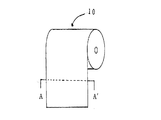
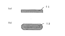
図1は本発明のシーラント巻取10の斜視図であり、図2(a)はキャスト法で製膜して巻き取ったシーラント11のA−A’面の側断面図であり、図2(b)はインフレーション製膜機で樹脂をチューブ状に押し出し、押し出したチューブ状シーラント内にクリーンエアを吹き込み、チューブ状シーラントの両端を製造ラインで耳切りをせず、帯状で巻き取ったシーラント12のA−A’面の側断面図である。
FIG. 1 is a perspective view of a sealant winding 10 according to the present invention, and FIG. 2A is a side sectional view of the AA ′ surface of a
前記シーラントは、共押し出し構成とすることも好ましく行われる。つまり、要求されるシーラントの厚みに応じて、2層以上の共押し出し構成とすることも可能である。例えば、シーラントの厚みとして90μmが要求される場合、加工方法によって単層で90μmの厚みが得られない場合がある。そのようなときには、45μm、45μmの2層共押し出し構成としてもよいし、30μm、30μm、30μmの3層共押し出し構成としてもよい。共押し出し構成の場合に用いる樹脂は、必ずしも同じ樹脂ではなくてもよいが、十分な層間強度が得られるような樹脂を選択する必要がある。 It is also preferable that the sealant has a co-extrusion structure. That is, it is possible to adopt a co-extrusion structure of two or more layers according to the required sealant thickness. For example, when 90 μm is required as the thickness of the sealant, a thickness of 90 μm may not be obtained as a single layer depending on the processing method. In such a case, a two-layer coextrusion configuration of 45 μm and 45 μm may be employed, or a three-layer coextrusion configuration of 30 μm, 30 μm, and 30 μm may be employed. The resin used in the co-extrusion configuration is not necessarily the same resin, but it is necessary to select a resin that can provide sufficient interlayer strength.
通常、シーラントの厚みは10〜200μm程度であるが、シーラントが厚いと後述する総アウトガス量が増加するため、シーラントの総厚みは120μm以下が好ましい。 Usually, the thickness of the sealant is about 10 to 200 μm, but if the sealant is thick, the total outgas amount described later increases, so the total thickness of the sealant is preferably 120 μm or less.
前記シーラント11、12に用いる樹脂としては、高密度ポリエチレン(HDPE)、中密度ポリエチレン(MDPE)、低密度ポリエチレン(LDPE)、直鎖状低密度ポリエチレン(LLDPE)などのポリエチレン(PE)、ポリプロピレン(PP)、ポリブテン、ポリメチルペンテンなどの単独重合体や、エチレン、プロピレン、ブテン、メチルペンテンなどのオレフィンから選ばれる2つ以上のモノマーの共重合体、例えばエチレン−プロピレン共重合体等が挙げられ、これら2つ以上の混合物を用いることも可能であり、また、ある種の官能基を導入したグラフトポリマー、例えば無水マレイン酸グラフトポリプロピレンのような樹脂、エチレン−α、β不飽和カルボン酸共重合体を主骨格とするエチレン系共重合体を用いることも可能であるが、クリーン性の面からはメルトインデックス(MI)=0.1〜20(g/10分・190℃)で、かつ酸化防止剤、アンチブロッキング剤、滑剤等の添加物を含まないLDPEが最適である。LDPEのメルトインデックス(MI)が0.1〜20(g/10分・190℃)が好ましいとするのは、メルトインデックス(MI)の低い樹脂を用いたほうが、低分子量成分が少ないため成形時の熱安定性に優れ、クリーン性が高い積層材料が得られるためである。
Examples of the resin used for the
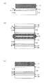
図3(a)は、シーラント11の片面に接着剤層を介して蒸着フィルム層を積層した積層体の断面図であり、シーラント11、接着剤層13、蒸着フィルム層15が順次積層されている。また図3(b)は、シーラント12の両面に接着剤層を介して蒸着フィルム層、ナイロン層を積層した積層体の断面図であり、シーラント12、接着剤層13、蒸着フィルム層15、接着剤層17、ナイロン層18が順次積層されている。また図3(c)は、シーラント11の片面に接着剤層を介して蒸着フィルム層、ナイロン層を積層した積層体の断面図であり、シーラント11、接着剤層13、蒸着フィルム層16、接着剤層17、ナイロン層18が順次積層されている。蒸着フィルム層、シーラント層以外に、ポリエチレンテレフタレート(PET)、ナイロン、エチレン−酢酸ビニル共重合体ケン化物フィルム(EVOHフィルム)等からなるフィルム層が、突き刺し強度等の機械的強度を補うためなど目的に合わせて適宜選択される。
FIG. 3A is a cross-sectional view of a laminate in which a vapor deposition film layer is laminated on one side of the
前記蒸着フィルム層15、16あるいはナイロン層18の積層方法としては、接着剤層13及び17を介して公知のドライラミネート法、ノンソルベントラミネート法などで積層可能である。前記接着剤層13、17に用いる接着剤としては、ポリウレタン系、ポリエステル系、ポリエーテル系、及びそれらを主体とした混合物などが一般的に用いられるが、Sn化合物及びSi化合物を含有せず、溶出成分の少ない接着剤が好ましく、かつ塗布量は必要最低限とすることが好ましい。接着性樹脂を用いることも可能である。また、何らかの表面改質によりダイレクトラミネーション、あるいはサンドラミネーションをすることも好ましく行われる。また、ラミネートする面の活性を上げるために、コロナ処理、火炎処理、プラズマ処理、オゾン処理等の表面処理をすることも可能である。
The vapor
サンドラミネーションに用いるラミネーション用樹脂としては、エチレンアクリル酸共重合体、メタクリル酸共重合体、エチレンアクリレート共重合体、メタアクリレート共重合体、エチレン酢酸ビニル共重合体、変性マレイン酸共重合体などが用いられる。接着剤をアンカーコートしてもよいが、クリーン性の面からアンカーコートをせず、酸成分等の分解が少ないポリエチレンを用いるサンドラミネーションをする方法がより好ましい。 Examples of the lamination resin used for the sand lamination include ethylene acrylic acid copolymer, methacrylic acid copolymer, ethylene acrylate copolymer, methacrylate copolymer, ethylene vinyl acetate copolymer, and modified maleic acid copolymer. Used. The adhesive may be anchor-coated, but from the viewpoint of cleanliness, an anchor coat is not performed, and a method of sand lamination using polyethylene with little decomposition of acid components and the like is more preferable.
図3(a)、(b)の蒸着フィルム層15は、蒸着フィルム基材層14上に、蒸着薄膜層(A層)と、少なくとも水溶性高分子を含むコーティング剤よりなる被膜層(B層)とが順次積層された蒸着フィルムである。図3(c)の蒸着フィルム層16は、蒸着フィルム基材層14上に蒸着薄膜層(A層)と、少なくとも水溶性高分子を含むコーティング剤よりなる被膜層(B層)と、更に蒸着薄膜層(C層)と、少なくとも水溶性高分子を含むコーティング剤よりなる被膜層(D層)とが順次積層されている蒸着フィルムである。図3(a)、(b)の蒸着フィルム層15と比較して、図3(c)の蒸着フィルム層16ではより高いガスバリア性を付与することが可能である。どちらの蒸着フィルムを用いる場合も、ナイロンフィルム等の他のフィルム層を設ける場合には、蒸着薄膜層上に他のフィルム層を設けることが好ましい。
The vapor
前記蒸着フィルム基材層14はプラスチック材料であり、PETフィルム、ポリエチレンナフタレート等のポリエステルフィルム、ナイロンフィルム、ポリプロピレンフィルム(PPフィルム)、ポリエチレンフィルム、EVOHフィルム、ポリスチレンフィルム、ポリカーボネートフィルム、ポリアクリロニトリルフィルム、ポリイミドフィルムなどが選択され、延伸、未延伸のどちらを用いることも可能であるが、耐熱性の面から二軸延伸PETフィルムが特に好ましく用いられる。薄膜層あるいは他のフィルムを接着させる面にコロナ処理、低温プラズマ処理等を施すことでより良好な接着強度が得られる。
The vapor deposition
前記蒸着フィルム基材層14の厚さは特に制限を受けるものではないが、蒸着薄膜層(A層およびC層)、被膜層(B層およびD層)を形成する場合の加工性を考慮すると、3〜200μmの範囲が好ましく、特に6〜30μmとすることがより好ましい。
The thickness of the vapor deposition
また、量産性を考慮すると、連続的に前記各層を形成することができるように、長尺状の連続フィルムを用いることが好ましい。 In consideration of mass productivity, it is preferable to use a long continuous film so that the respective layers can be continuously formed.
前記蒸着薄膜層(A層およびC層)の薄膜形成材料としては、アルミニウム、マグネシウム、ケイ素、錫、チタン、亜鉛、ジルコニウム、カルシウム、ニッケル等から選択される金属、またはこれら金属の酸化物、窒化物、フッ化物のうちのいずれか1種、あるいは2種以上の混合物が挙げられる。透明性を考慮する場合には、無機化合物を用いることが好ましく、特に酸化アルミニウム、酸化ケイ素は蒸着膜単体での水蒸気、酸素等のガスバリア性に優れ、さらに高い透明性を有するために内容物の認識が可能となる点でより好ましい。 As a thin film forming material of the vapor deposition thin film layer (A layer and C layer), a metal selected from aluminum, magnesium, silicon, tin, titanium, zinc, zirconium, calcium, nickel, etc., or an oxide or nitridation of these metals Or a mixture of two or more thereof. In consideration of transparency, it is preferable to use an inorganic compound. In particular, aluminum oxide and silicon oxide are excellent in gas barrier properties such as water vapor and oxygen in a vapor deposition film alone, and have higher transparency, so It is more preferable in that recognition is possible.
また、蒸着薄膜層A層およびC層に用いる薄膜形成材料は、それぞれ同じ材料でも異なる材料でも特に制限はなく、要求されるガスバリア性に応じてその組合せは特に限定されない。 The thin film forming materials used for the vapor-deposited thin film layers A and C are not particularly limited regardless of whether they are the same material or different materials, and the combination is not particularly limited depending on the required gas barrier properties.
蒸着薄膜層を形成する方法として種々存在するが、真空蒸着法やスパッタリング法、イオンプレーティング法、プラズマ気相成長法(CVD)などの薄膜形成方法を用いることが可能である。特に真空蒸着法は生産効率の点から特に優れている。真空蒸着法の加熱手段としては、電子線加熱方式や抵抗加熱方式、誘導加熱方式のいずれかが好ましい。また、蒸着薄膜層と基材の密着性および蒸着薄膜層の緻密性を向上させるために、プラズマアシスト法やイオンビームアシスト法を用いて蒸着することも可能である。また、蒸着の際に、酸素ガス等を吹き込む反応蒸着を行ってもよい。 There are various methods for forming a deposited thin film layer, and thin film forming methods such as a vacuum deposition method, a sputtering method, an ion plating method, and a plasma vapor deposition method (CVD) can be used. In particular, the vacuum deposition method is particularly excellent in terms of production efficiency. As a heating means of the vacuum evaporation method, any of an electron beam heating method, a resistance heating method, and an induction heating method is preferable. Moreover, in order to improve the adhesiveness of a vapor deposition thin film layer and a base material, and the denseness of a vapor deposition thin film layer, it is also possible to vapor-deposit using a plasma assist method or an ion beam assist method. Moreover, you may perform the reactive vapor deposition which blows oxygen gas etc. in the case of vapor deposition.
蒸着薄膜層の厚みは、用いられる蒸着材料の種類等により最低条件が異なるが、1〜300nmの範囲であることが望ましい。より好ましくは5〜100nmの範囲にあることが望ましい。蒸着薄膜層の厚みが1nm未満であると、基材の全面に製膜できないおそれがある。また、蒸着薄膜層の厚みが300nmを超える場合には薄膜にフレキシビリティを保持させることができず、外的要因により薄膜に亀裂を生じさせるおそれがあるために好ましくない。 The minimum thickness of the vapor-deposited thin film layer varies depending on the type of vapor deposition material used, but is preferably in the range of 1 to 300 nm. More preferably, it is in the range of 5 to 100 nm. If the thickness of the vapor-deposited thin film layer is less than 1 nm, the film may not be formed on the entire surface of the substrate. Further, when the thickness of the deposited thin film layer exceeds 300 nm, it is not preferable because flexibility cannot be maintained in the thin film, and the thin film may be cracked due to external factors.
次いで、少なくとも水溶性高分子を含むコーティング剤よりなる被膜層(B層およびD層)について説明する。本発明において、被膜層は少なくとも水溶性高分子を含む必要がある。このような水溶性高分子としては、ポリビニルアルコール(PVA)、ポリビニルピロリドン、デンプン、メチルセルロース、カルボキシメチルセルロース、アルギン酸ナトリウム等の水溶性を示すものであれば特に限定されることはない。これらの中で、PVAを用いた場合は特にガスバリア性に優れる。ここでのPVAは、酢酸基が数十%残存している部分ケン化PVAから酢酸基が数%しか残存していない完全ケン化PVAまで、一般にポリ酢酸ビニルをケン化して得られるものであれば特に限定されるものではない。これを蒸着薄膜層上にコーティングした後、加熱乾燥することで被膜層が形成される。 Next, coating layers (B layer and D layer) made of a coating agent containing at least a water-soluble polymer will be described. In the present invention, the coating layer needs to contain at least a water-soluble polymer. Such a water-soluble polymer is not particularly limited as long as it exhibits water solubility such as polyvinyl alcohol (PVA), polyvinyl pyrrolidone, starch, methyl cellulose, carboxymethyl cellulose, sodium alginate and the like. Among these, when PVA is used, the gas barrier property is particularly excellent. The PVA here is generally obtained by saponifying polyvinyl acetate, from partially saponified PVA in which several tens percent of acetate groups remain to fully saponified PVA in which only several percent of acetate groups remain. There is no particular limitation. After coating this on a vapor-deposited thin film layer, the coating layer is formed by heating and drying.
更に、被膜層(B層およびD層)が、水溶性高分子と、(a)1種以上の金属アルコキシド、または/および、その加水分解物、または(b)塩化錫、の少なくともいずれか1つを含む水溶液、あるいは水とアルコールとの混合溶液とを主剤とするコーティング剤からなる層であることが好ましい。例えば、水溶性高分子と塩化錫とを水系(水、あるいは水とアルコールとの混合)溶媒で溶解させた溶液、あるいはこれに金属アルコキシドを直接、あるいは予め加水分解するなどの処理を施したものを混合した溶液を調製する。ここで用いられる水溶性高分子は前述したものを使用することが可能である。 Furthermore, the coating layer (B layer and D layer) is at least one of a water-soluble polymer, (a) one or more metal alkoxides and / or hydrolysates thereof, or (b) tin chloride. It is preferable that the layer is made of a coating agent mainly composed of an aqueous solution containing water or a mixed solution of water and alcohol. For example, a solution in which a water-soluble polymer and tin chloride are dissolved in an aqueous solvent (water or a mixture of water and alcohol), or a solution in which a metal alkoxide is directly or previously hydrolyzed. A mixed solution is prepared. As the water-soluble polymer used here, those described above can be used.
前記コーティング剤に使用される塩化錫は、塩化第一錫(SnCl2)、塩化第二錫(SnCl4)、あるいはそれらの混合物であってもよい。また、これらの塩化錫は無水物であっても、水和物であってもよい。 The tin chloride used in the coating agent may be stannous chloride (SnCl 2 ), stannic chloride (SnCl 4 ), or a mixture thereof. These tin chlorides may be anhydrous or hydrated.
また、前記金属アルコキシドとは、一般式M(OR)n(M:Si、Ti、Zr等の金属、R:CH3、C2H5等のアルキル基、n:自然数)で表される化合物である。具体的にはテトラエトキシシラン[Si(OC2H5)4]、トリイソポロポキシアルミニウム[Al(O−2’−C3H7)3]などが挙げられ、なかでもテトラエトキシシランは、加水分解後、水系の溶媒中において安定であるためより好ましい。 The metal alkoxide is a compound represented by the general formula M (OR) n (M: metal such as Si, Ti, Zr, R: alkyl group such as CH 3 , C 2 H 5 , n: natural number). It is. Specifically, tetraethoxysilane [Si (OC 2 H 5 ) 4 ], triisoporopoxyaluminum [Al (O-2′-C 3 H 7 ) 3 ] and the like can be mentioned. It is more preferable because it is stable in an aqueous solvent after hydrolysis.
前記コーティング剤の塗布方法としては、グラビア印刷法、ディッピング法、ロールコーティング法、スクリーン印刷法、スプレー法等の公知の手法を用いることができる。 As the coating method of the coating agent, known methods such as a gravure printing method, a dipping method, a roll coating method, a screen printing method, and a spray method can be used.
被膜層(B層およびD層)の厚みは、乾燥後で100〜5000nmが好ましく、特に厚みが均一であり、200〜600nmの厚みであることがより好ましい。100nm未満の場合には塗膜の厚みが均一にならないおそれがあり、また、5000nmを超える場合にはクラックを生じ易くなる。 The thickness of the coating layer (B layer and D layer) is preferably 100 to 5000 nm after drying, particularly uniform in thickness, and more preferably 200 to 600 nm. If it is less than 100 nm, the thickness of the coating film may not be uniform, and if it exceeds 5000 nm, cracks tend to occur.
本発明のクリーンフィルムについて、定量的に規定したアウトイオン量、溶出Sn量、溶出Si量、フィルム表面のパーティクル(微粒子)数、アウトガスについて説明を加える。 The clean film of the present invention will be described in terms of quantitatively defined out ion amount, eluted Sn amount, eluted Si amount, number of particles (fine particles) on the film surface, and outgas.
アウトイオン量および溶出Sn量の抽出は同一条件で行う。抽出は、前記クリーンフィルムの内容物に接する面を22±3℃の雰囲気下において、1cm2当たり0.3mlの超純水で10分間行う。 The extraction of the out ion amount and the eluted Sn amount is performed under the same conditions. The extraction is performed for 10 minutes with 0.3 ml of ultrapure water per 1 cm 2 in an atmosphere of 22 ± 3 ° C. on the surface in contact with the contents of the clean film.
抽出液中のイオン濃度をイオンクロマトグラフ(IC)で測定した際の、塩素イオン、亜硝酸イオン、硝酸イオン、リン酸イオン、硫酸イオンの5種のアウトイオン量が各0.20ng/cm2以下であり、さらに、ナトリウムイオン、カリウムイオン、マグネシウムイオン、カルシウムイオン、塩素イオン、亜硝酸イオン、硝酸イオン、リン酸イオン、硫酸イオンの9種のアウトイオン量が各0.20ng/cm2以下であることが、クリーンフィルムにおいて要求される。また、抽出液中のSn濃度を結合誘導プラズマ質量分析計(ICP−MS)で測定した結果、0.5pg/cm2以下であることが要求される。 When the ion concentration in the extract was measured by an ion chromatograph (IC), the amount of five out ions of chlorine ion, nitrite ion, nitrate ion, phosphate ion and sulfate ion was 0.20 ng / cm 2 each. The amount of nine out ions of sodium ion, potassium ion, magnesium ion, calcium ion, chlorine ion, nitrite ion, nitrate ion, phosphate ion and sulfate ion is 0.20 ng / cm 2 or less. It is required in a clean film. Moreover, as a result of measuring Sn density | concentration in an extract with a coupling | bonding induction plasma mass spectrometer (ICP-MS), it is requested | required that it is 0.5 pg / cm < 2 > or less.
溶出Si量の抽出は、前記クリーンフィルムの内容物に接する面を22±3℃の雰囲気下において、1cm2当たり0.1mlの超純水で抽出を行う。抽出液中のSi量を測定する方法としては原子吸光分光光度分析計(AAS)、特にフレームレスAASが用いられる。クリーンフィルムにおいて、抽出液中のSi濃度は、0.5ng/cm2以下であることが要求される。 In the extraction of the amount of dissolved Si, the surface in contact with the contents of the clean film is extracted with 0.1 ml of ultrapure water per cm 2 in an atmosphere of 22 ± 3 ° C. As a method for measuring the amount of Si in the extract, an atomic absorption spectrophotometer (AAS), particularly a flameless AAS is used. In a clean film, the Si concentration in the extract is required to be 0.5 ng / cm 2 or less.
フィルム表面のパーティクルの抽出は、前記クリーンフィルムの内容物に接する面を1cm2当たり0.1mlの超純水で行う。抽出液中のパーティクル数の測定は、液中パーティクルカウンター(LPC)を用いて測定を行う。その結果、粒径1μm以上のパーティクル数が1個/cm2以下、粒径0.3μm以上のパーティクル数が125個/cm2以下であることが、クリーンフィルムにおいて好ましい。 Extraction of particles on the film surface is performed with 0.1 ml of ultrapure water per 1 cm 2 on the surface in contact with the contents of the clean film. The number of particles in the extract is measured using an in-liquid particle counter (LPC). As a result, the number of particles having a particle size of 1 μm or more is preferably 1 / cm 2 or less, and the number of particles having a particle size of 0.3 μm or more is preferably 125 / cm 2 or less in a clean film.
アウトガスは、前記クリーンフィルムを一定面積サンプリングし、パージアンドトラップ(P&T)装置で80℃、10分間加熱した後、ガスクロマトグラフ−質量計(GC−MS)にて測定する。総アウトガス量がヘキサデカン換算で1500ng/cm2未満であることが好ましい。また、環状シロキサン合計量がシロキサン六量体換算で2.5ng/cm2未満であることが好ましい。 The outgas is measured with a gas chromatograph-mass meter (GC-MS) after sampling the clean film over a certain area and heating it with a purge and trap (P & T) apparatus at 80 ° C. for 10 minutes. The total outgas amount is preferably less than 1500 ng / cm 2 in terms of hexadecane. The total amount of cyclic siloxane is preferably less than 2.5 ng / cm 2 in terms of siloxane hexamer.
前記クリーンフィルムのクリーン度を評価する際には、抽出作業や測定時にコンタミネーションが生じないように細心の注意を払う必要があり、パーティクルを高性能フィルター等で除去した高清浄環境のクリーンルーム内で作業を行うことが好ましい。米国規格において、粒径0.5μm以上のパーティクル数が1立方フィート中に100個以下の清浄度をクラス100、10000個以下の清浄度をクラス10000と呼ぶ。クリーンフィルムからのアウトイオン、溶出Sn量、溶出Si量を評価する際には、クラス100以下のクリーンルームであることが好ましい。また、抽出中に環境からイオンを取り込むことがないように、クリーンルーム環境のイオンが少ないことが重要であるため、ケミカルフィルターを有するクリーンルーム内で作業を行うことが好ましい。
クリーンフィルムからのアウトイオン、溶出Sn量、溶出Si量を評価する際には、クラス100以下のクリーンルームであることが好ましい。また、抽出中に環境からイオンを取り込むことがないように、クリーンルーム環境のイオンが少ないことが重要であるため、ケミカルフィルターを有するクリーンルーム内で作業を行うことが好ましい。また、抽出に用いる超純水は、比抵抗18mΩ・cm以上で、イオンやSn、Siレベルが低いことが望まれ、より好ましくは検出限界以下であることが望ましい。
When evaluating the cleanliness of the clean film, it is necessary to pay close attention to prevent contamination during extraction work and measurement. In a clean room with a high clean environment where particles are removed with a high-performance filter, etc. It is preferable to work. In the US standard, the cleanliness of 100 or less particles per cubic foot having a particle size of 0.5 μm or more is called class 100, and the cleanliness of 10,000 or less is called class 10000. When evaluating the out ion from the clean film, the eluted Sn amount, and the eluted Si amount, a clean room of class 100 or less is preferable. Also, since it is important that the number of ions in the clean room environment is small so that ions are not taken in from the environment during extraction, it is preferable to work in a clean room having a chemical filter.
When evaluating the out ion from the clean film, the eluted Sn amount, and the eluted Si amount, a clean room of class 100 or less is preferable. Also, since it is important that the number of ions in the clean room environment is small so that ions are not taken in from the environment during extraction, it is preferable to work in a clean room having a chemical filter. The ultrapure water used for extraction is desired to have a specific resistance of 18 mΩ · cm or more and a low level of ions, Sn, and Si, and more preferably below the detection limit.
また、クリーンフィルムの内面に付着するパーティクル数を評価する際には、抽出に用いる超純水のパーティクルレベルが低いことが望まれる。少なくとも、超純水に含まれる粒径0.3μm以上のパーティクル数が2個/ml以下であること、さらに好ましくは0個/mlであることが望まれる。また、環境中の浮遊パーティクルを取り込むことがないよう、クラス1000以下のクリーンルーム内で作業を行うことが好ましい。 Moreover, when evaluating the number of particles adhering to the inner surface of the clean film, the particle level of ultrapure water used for extraction is desired to be low. It is desired that at least the number of particles having a particle diameter of 0.3 μm or more contained in ultrapure water is 2 / ml or less, more preferably 0 / ml. Also, it is preferable to work in a clean room of class 1000 or less so as not to capture airborne particles in the environment.
以下に、アウトイオン、溶出Sn量、溶出Si量、アウトガス測定について、抽出から測定までの手順を示す。 Hereinafter, procedures from extraction to measurement will be described for out ion, eluted Sn amount, eluted Si amount, and outgas measurement.
第一に、梱包されたクリーンフィルムをコンタミネーション防ぐために測定直前に開封する。フィルムが袋状でない場合には、コンタミネーションを防ぐためにインパルスシールあるいはヒートシールを行い袋状にする。サンプル量が少ない等の理由から三方袋状にできないフィルムを評価する場合には、フィルムを一定面積サンプリングし、容器からの溶出が少ないポリプロピレン容器やテフロン(登録商標)容器等にフィルムを入れて、フィルム表面積当たり0.3mlの超純水でフィルム両面から抽出を行ってもよい。製袋品については、クリーン度評価時のコンタミネーションを避けるために、一定面積をサンプリングすることなく、その状態のまま評価することが好ましい。 First, the packaged clean film is opened immediately before measurement in order to prevent contamination. If the film is not in a bag shape, it is formed into a bag shape by impulse sealing or heat sealing to prevent contamination. When evaluating a film that cannot be made into a three-sided bag because the sample amount is small, sample the film in a certain area, and put the film in a polypropylene container or Teflon (registered trademark) container with little elution from the container. Extraction may be performed from both sides of the film with 0.3 ml of ultrapure water per film surface area. In order to avoid contamination at the time of evaluating the cleanness, it is preferable to evaluate a bag-made product as it is without sampling a certain area.
本発明のクリーンフィルムにおいては、袋サイズの異なるサンプルであっても、サンプル表面積当たりの超純水量を合わせることで、クリーン度測定結果の比較が可能である。 In the clean film of the present invention, it is possible to compare the measurement results of cleanliness by combining the amount of ultrapure water per sample surface area even with samples having different bag sizes.
まず、包装袋中に、袋内表面積1cm2当たり0.3mlの超純水を静かに入れ、開口部を三つ折りにしてクリップ止めする。シールする場合には、測定時開口部を開く際のコンタミネーションがないように注意を払う必要がある。袋内面全体に超純水が接していればよく、袋内表面積1cm2当たりに必要な超純水の量は測定の条件に応じて適宜変えることが可能である。 First, 0.3 ml of ultrapure water per 1 cm 2 of the bag's surface area is gently put into the packaging bag, and the opening is folded in three and clipped. When sealing, it is necessary to pay attention so that there is no contamination when opening the opening during measurement. It is sufficient that ultrapure water is in contact with the entire inner surface of the bag, and the amount of ultrapure water required per 1 cm 2 of the bag surface area can be appropriately changed according to the measurement conditions.
平袋の場合、包装袋中の超純水が袋の内面全部に行き渡るように、包装袋を横にして1回転当たり約6秒の速度でゆっくりと5回転させる。次に、包装袋の面を変えて、同様の作業を行った後、周囲からイオン取り込むことがない環境、好ましくはケミカルフィルター付きのドラフト内で、包装袋を片面につき5分、計10分間放置する。 In the case of a flat bag, the packaging bag is turned sideways and slowly rotated 5 times at a speed of about 6 seconds per rotation so that the ultrapure water in the packaging bag spreads over the entire inner surface of the bag. Next, after changing the surface of the packaging bag and performing the same operation, leave the packaging bag for 5 minutes on each side for 10 minutes in an environment where ions are not taken in from the surroundings, preferably in a fume hood with a chemical filter. To do.
ガゼット袋の場合は、包装袋中の超純水が袋の内面全部に行き渡るように、包装袋を横にして1回転当たり約6秒の速度でゆっくりと5回転させる。次に、折り込み部分を下にして、包装袋中の超純水が袋の内面全部に行き渡るように、包装袋を横にして1回転当たり約6秒の速度でゆっくりと5回転させる。この作業を4面全てについて行う。その後、包装袋を周囲からイオン取り込むことがない環境、好ましくはケミカルフィルター付きのドラフト内で片面につき5分、計10分間放置する。 In the case of a gusset bag, the packaging bag is turned sideways and slowly rotated 5 times at a speed of about 6 seconds per rotation so that the ultrapure water in the packaging bag spreads over the entire inner surface of the bag. Next, with the folded portion down, the packaging bag is turned sideways and slowly rotated 5 times at a speed of about 6 seconds per rotation so that the ultrapure water in the packaging bag spreads over the entire inner surface of the bag. This operation is performed for all four surfaces. Thereafter, the packaging bag is left in an environment where ions are not taken in from the surroundings, preferably in a fume hood with a chemical filter, for 5 minutes per side for 10 minutes in total.
国際ディスクドライブ協会(IDEMA)STANDARDSのDocument No.M13−99 Measurement of Extractable/Leachable Cation Comtamination Levels on Drive Components by Ion Chromatography、M22−99 Measurement of Extractable/Leachable Anion Comtamination Levels on Drive Components by Ion Chromatographyでは、常温抽出の場合、部品を容器に入れ、メカニカルシェイカーで10分間振とうする規定になっているが、包装袋をシェイカーで振とうすることは困難であり、包装袋をカットして容器に入れて抽出するのでは包装袋内面のパーティクルだけでなく、外面のパーティクルも抽出してしまうため、本発明のクリーンフィルムにおいては上記のような抽出方法とした。 Document No. of International Disk Drive Association (IDEMA) STANDARDS. M13-99 Measurement of Extractable / Leachable Cation Comtamination Levels on Drive Components by Ion Chromatography, in M22-99 Measurement of Extractable / Leachable Anion Comtamination Levels on Drive Components by Ion Chromatography, the case of normal temperature extraction, put the parts in a container, mechanical shaker However, it is difficult to shake the packaging bag with a shaker, and it is not only the particles inside the packaging bag that are extracted by cutting the packaging bag into a container, Outside Since thus also the particle extraction, in clean film of the present invention was extracted method described above.
次に、IC測定あるいはICP−MS測定を行う。溶出Snに関しては長時間放置するとSnが沈降するため、抽出後、すぐにICP−MS測定を行う。包装袋にサンプリングチューブを入れるか、超純水を入れたときのアウトイオンが検出限界以下である容器に抽出液を移してもよい。後者の場合には、包装袋外面からの汚染を避けるため、注ぎ出しの抽出液を数ml捨ててから、容器に移す。溶出Sn量測定の場合には加熱抽出も好ましく行われ、クリーンルーム内のクリーンオーブンで80℃、30分加熱し、22±3℃の室温で30分放置してから、ICP−MS測定を行う。 Next, IC measurement or ICP-MS measurement is performed. As for the eluted Sn, since it settles when left for a long time, ICP-MS measurement is performed immediately after extraction. A sampling tube may be put into a packaging bag, or you may move an extract to the container whose out ion when putting ultrapure water is below a detection limit. In the latter case, in order to avoid contamination from the outer surface of the packaging bag, several ml of the poured out extract is discarded and transferred to a container. In the case of measuring the amount of eluted Sn, heat extraction is also preferably performed. After heating in a clean oven in a clean room at 80 ° C. for 30 minutes and leaving at room temperature of 22 ± 3 ° C. for 30 minutes, ICP-MS measurement is performed.
IC測定における対象イオンは、カチオンとしてはナトリウムイオン、カリウムイオン、マグネシウムイオン、カルシウムイオン、アニオンとして塩素イオン、亜硝酸イオン、硝酸イオン、リン酸イオン、硫酸イオンである。IC装置、カラム等は前記IDEMA STANDARDSのDocument No.M13−99、M22−99に準拠する。IC装置としては、DIONEX社のDX−500(サプレッサー方式)あるいは同等レベルの装置が好ましく、上記イオンを効率良く分離、検出するため、カチオンの分離カラムはDIONEX製のCS12A(基材:エチレンビニルベンゼン−ジビニルベンゼン、交換基:カルボン酸/スルホン酸)、溶離液は20mMメタンスルホン酸、アニオンの分離カラムはDIONEX製のAS4A−SC(基材:エチレンビニルベンゼン−ジビニルベンゼン、交換基:4級アルカノールアミン)、溶離液は1.8mM Na2CO3と1.7mM NaHCO3の混合溶液が好ましく用いられる。 The target ions in IC measurement are sodium ions, potassium ions, magnesium ions, calcium ions as cations, and chlorine ions, nitrite ions, nitrate ions, phosphate ions, and sulfate ions as anions. IC devices, columns, etc. are the IDEMA STANDARDS Document No. Conforms to M13-99 and M22-99. As the IC device, DX-500 (suppressor system) manufactured by DIONEX or an equivalent level device is preferable. In order to efficiently separate and detect the above ions, the cation separation column is CS12A (base material: ethylene vinyl benzene) manufactured by DIONEX. -Divinylbenzene, exchange group: carboxylic acid / sulfonic acid), eluent is 20 mM methanesulfonic acid, anion separation column is AS4A-SC manufactured by DIONEX (base material: ethylene vinylbenzene-divinylbenzene, exchange group: quaternary alkanol) Amine) and eluent are preferably a mixed solution of 1.8 mM Na 2 CO 3 and 1.7 mM NaHCO 3 .
サンプル導入については、検出感度の面から、ループではなく濃縮装置(カラム)使用が好ましく、濃縮量は2〜10mlが適する。 For sample introduction, from the viewpoint of detection sensitivity, it is preferable to use a concentrator (column) instead of a loop, and a concentration of 2 to 10 ml is suitable.
サンプル測定前に、ブランク測定として抽出に用いた超純水中のイオン量を測定することが必ず行われる。検量線は、ブランク以外に3点を通る直線で、相関係数0.99以上であることが好ましい。 Prior to sample measurement, it is always necessary to measure the amount of ions in ultrapure water used for extraction as a blank measurement. The calibration curve is a straight line passing through three points other than the blank, and preferably has a correlation coefficient of 0.99 or more.
ICP−MS装置としては、通常、四重極型の質量分析計を用いて、Snの質量数120を指定して測定を行う。検量線は、超純水ブランク以外に2点以上を通る直線で、相関係数0.99以上であることが好ましい。通常、分析では10σを定量下限、3σを検出限界とするが、本発明のクリーンフィルムの分析においても3σを検出限界とすることが行われる。各イオンの検出限界は0.05ng/cm2以下、Snの検出限界は0.5pg/cm2未満であることが好ましい。 As an ICP-MS apparatus, usually, a quadrupole mass spectrometer is used to specify the mass number 120 of Sn and perform measurement. The calibration curve is a straight line passing through two or more points other than the ultrapure water blank, and preferably has a correlation coefficient of 0.99 or more. Normally, in the analysis, 10σ is the lower limit of quantification and 3σ is the detection limit, but in the analysis of the clean film of the present invention, 3σ is also set as the detection limit. The detection limit of each ion is preferably 0.05 ng / cm 2 or less, and the detection limit of Sn is preferably less than 0.5 pg / cm 2 .
前記測定で得られた数値から、包材1cm2当たりのアウトイオン量、溶出Sn量を計算する式を以下に示す。 Formulas for calculating the amount of out ions and the amount of eluted Sn per 1 cm 2 of the packaging material from the numerical values obtained by the measurement are shown below.
包材1cm2当たりのアウトイオン量(ng/cm2)=[包装袋のアウトイオン量(ppb)−抽出に用いた超純水のイオン量(ppb)×抽出液量(ml)]/超純水抽出した包装袋の表面積(cm2)
包材1cm2当たりのSn量(pg/cm2)=[包装袋の溶出Sn量(ppt)×抽出液量(ml)]/超純水抽出した包装袋の表面積(cm2)
さらに、本発明のクリーンフィルムの溶出Siについて、抽出から測定までの手順を示す。
Out ion amount per 1 cm 2 of packaging material (ng / cm 2 ) = [Out ion amount of packaging bag (ppb) −Ion amount of ultrapure water used for extraction (ppb) × Extraction liquid amount (ml)] / Over Surface area of packaging bag extracted with pure water (cm 2 )
Sn amount per 1 cm 2 of packaging material (pg / cm 2 ) = [elution Sn amount of packaging bag (ppt) × extracted liquid amount (ml)] / surface area of packaging bag extracted with ultrapure water (cm 2 )
Furthermore, about the elution Si of the clean film of this invention, the procedure from extraction to a measurement is shown.
第一に、梱包されたクリーンフィルムをコンタミネーション防ぐために測定直前に開封する。フィルムが袋状でない場合には、コンタミネーションを防ぐためにインパルスシールあるいはヒートシールを行い袋状にする。まず、包装袋中に、袋内表面積1cm2当たり0.1mlの超純水を静かに入れ、開口部を三つ折りにしてクリップ止めする。シールする場合には、測定時開口部を開く際のコンタミネーションがないように注意を払う必要がある。袋内面全体に超純水が接していればよく、袋内表面積1cm2当たりに必要な超純水の量は測定の条件に応じて適宜変えることが可能である。 First, the packaged clean film is opened immediately before measurement in order to prevent contamination. If the film is not in a bag shape, it is formed into a bag shape by impulse sealing or heat sealing to prevent contamination. First, 0.1 ml of ultrapure water per 1 cm 2 of the bag inner surface area is gently put into the packaging bag, and the opening is folded in three and clipped. When sealing, it is necessary to pay attention so that there is no contamination when opening the opening during measurement. It is sufficient that ultrapure water is in contact with the entire inner surface of the bag, and the amount of ultrapure water required per 1 cm 2 of the bag surface area can be appropriately changed according to the measurement conditions.
平袋の場合、包装袋中の超純水が袋の内面全部に行き渡るように、包装袋を横にして1回転当たり約6秒の速度でゆっくりと5回転させる。次に、包装袋の面を変えて、同様の作業を行った後、周囲からイオン取り込むことがない環境、好ましくはケミカルフィルター付きのドラフト内で、包装袋を片面につき5分、計10分間放置する。 In the case of a flat bag, the packaging bag is turned sideways and slowly rotated 5 times at a speed of about 6 seconds per rotation so that the ultrapure water in the packaging bag spreads over the entire inner surface of the bag. Next, after changing the surface of the packaging bag and performing the same operation, leave the packaging bag for 5 minutes on each side for 10 minutes in an environment where ions are not taken in from the surroundings, preferably in a fume hood with a chemical filter. To do.
ガゼット袋の場合は、包装袋中の超純水が袋の内面全部に行き渡るように、包装袋を横にして1回転当たり約6秒の速度でゆっくりと5回転させる。次に、折り込み部分を下にして、包装袋中の超純水が袋の内面全部に行き渡るように、包装袋を横にして1回転当たり約6秒の速度でゆっくりと5回転させる。この作業を4面全てについて行う。その後、包装袋を周囲からイオン取り込むことがない環境、好ましくはケミカルフィルター付きのドラフト内で片面につき5分、計10分間放置する。 In the case of a gusset bag, the packaging bag is turned sideways and slowly rotated 5 times at a speed of about 6 seconds per rotation so that the ultrapure water in the packaging bag spreads over the entire inner surface of the bag. Next, with the folded portion down, the packaging bag is turned sideways and slowly rotated 5 times at a speed of about 6 seconds per rotation so that the ultrapure water in the packaging bag spreads over the entire inner surface of the bag. This operation is performed for all four surfaces. Thereafter, the packaging bag is left in an environment where ions are not taken in from the surroundings, preferably in a fume hood with a chemical filter, for 5 minutes per side for 10 minutes in total.
次にAAS測定を行う。 Next, AAS measurement is performed.
溶出Si量測定の場合には、加熱抽出も好ましく行われ、クリーンルーム内のクリーンオーブンで80℃、30分加熱し、22±3℃の室温で30分間放置してから、AAS測定を行う。AAS装置としては、通常、フレームレスタイプが用いられ、Siの測定波長は251.6nm、一般的な加熱条件プログラムで測定する。検量線は、ブランク以外に3点以上および原点を通る直線で、相関係数0.99以上であることが好ましい。Siの定量下限(10σ)は0.5ng/cm2未満であることが好ましい。 In the case of measuring the amount of eluted Si, heating extraction is also preferably performed. After heating in a clean oven in a clean room at 80 ° C. for 30 minutes and leaving at room temperature of 22 ± 3 ° C. for 30 minutes, AAS measurement is performed. As the AAS apparatus, a frameless type is usually used, and the measurement wavelength of Si is 251.6 nm, and measurement is performed with a general heating condition program. The calibration curve is a straight line passing through three or more points and the origin in addition to the blank, and preferably has a correlation coefficient of 0.99 or more. The lower limit of quantification (10σ) of Si is preferably less than 0.5 ng / cm 2 .
前記測定で得られた数値から、包材1cm2当たりの溶出Si量を計算する式を以下に示す。 An equation for calculating the amount of dissolved Si per 1 cm 2 of the packaging material from the numerical values obtained by the measurement is shown below.
包材1cm2当たりの溶出Si量(pg/cm2)=[包装袋の溶出Si量(ppb)×抽出液量(ml)]/超純水抽出した包装袋の表面積(cm2)
次に、本発明のクリーンフィルムの内表面に付着したパーティクルについて、抽出から測定までの手順を示す。
Elution Si amount per 1 cm 2 of packaging material (pg / cm 2 ) = [elution Si amount of packaging bag (ppb) × extraction liquid amount (ml)] / surface area of packaging bag extracted with ultrapure water (cm 2 )
Next, a procedure from extraction to measurement is shown for particles adhering to the inner surface of the clean film of the present invention.
本発明のクリーンフィルムにおけるパーティクルの評価手法としては、もっとも一般的である光散乱検出器を有するLPCを用いる。該LPCは1μm未満のパーティクルも測定可能であるという特徴があるが、ハンドリングの際に発生する気泡とパーティクルを区別することができない。IDEMA STANDARDSのDocument No.M9−98 PARTICULATE CONTAMINATION TEST METHODS FOR HARD DISK DRIVE COMPONENTSでは、ハードディスクドライブの部品のパーティクルを、超音波またはシェイカーで抽出すると規定されているが、超音波が包装袋材料に及ぼす影響が明らかになっていないため、包装袋材料自体を破壊してパーティクルを発生させる可能性があること、シェイカーによる振とうは包装袋からのパーティクル脱離を促進するどころか気泡を発生させるおそれがあることにより、本発明では気泡の発生を最低限に抑える抽出手順とした。 As a method for evaluating particles in the clean film of the present invention, LPC having the most common light scattering detector is used. The LPC has a feature that particles having a size of less than 1 μm can be measured. However, the bubbles generated during handling cannot be distinguished from the particles. Document No. of IDEMA STANDARDS. M9-98 PARTICLATE CONTINATIONATION TEST METHODS FOR HARD DISK DRIVE COMPONENTS stipulates that particles of hard disk drive components are extracted with ultrasonic waves or shakers, but the effect of ultrasonic waves on packaging bag materials has not been clarified. Therefore, in the present invention, there is a possibility of generating particles by destroying the packaging bag material itself, and that shaking by the shaker may generate bubbles rather than promoting particle detachment from the packaging bag. Extraction procedure to minimize the occurrence of
以下に、抽出からLPC測定までの手順を示す。 The procedure from extraction to LPC measurement is shown below.
第一に、梱包されたクリーンフィルムあるいは包装袋をコンタミネーション防ぐために測定直前に開封する。フィルムが巻取りあるいは枚葉である場合には、コンタミネーションを防ぐためにインパルスシールあるいはヒートシールを行い、三方袋状にすることが好ましく行われる。 First, in order to prevent contamination, the packaged clean film or packaging bag is opened immediately before measurement. In the case where the film is wound or single-wafered, it is preferably performed to form a three-sided bag by performing impulse sealing or heat sealing in order to prevent contamination.
平袋の場合、図4に示すようなボックスに包装袋を入れ、包材1cm2当たり0.3mlの超純水を気泡が発生しないように静かに入れ、開口部を三つ折りしてクリップ止めする。袋内面全体に超純水が接していればよく、袋内表面積1cm2当たりに必要な超純水の量は測定の条件に応じて適宜変えることが可能である。次に、包装袋をボックスごと横にして、1回転当たり約6秒の速度で、中に入れた超純水が包材内面を洗うように、ゆっくりと5回転させる。包材の面を変えて、同様の作業を行った後、環境からパーティクルを取り込まない環境下でボックスに入れた包装袋を立たせたまま、LPC装置のサンプリング位置で15分間静置する。 In the case of a flat bag, put the packaging bag in a box as shown in Fig. 4 and gently put 0.3 ml of ultrapure water per 1 cm 2 of packaging material so that no bubbles are generated, and fold the opening in three and clip it. To do. It is sufficient that ultrapure water is in contact with the entire inner surface of the bag, and the amount of ultrapure water required per 1 cm 2 of the bag surface area can be appropriately changed according to the measurement conditions. Next, the packaging bag is placed sideways along with the box, and is slowly rotated 5 times so that the ultrapure water contained therein can wash the inner surface of the packaging material at a speed of about 6 seconds per rotation. After changing the surface of the packaging material and performing the same operation, the packaging bag placed in the box is left standing in an environment in which particles are not taken in from the environment, and is allowed to stand for 15 minutes at the sampling position of the LPC device.
ガゼット袋の場合には、包材1cm2当たり0.3mlの超純水を気泡が発生しないように静かに入れ、開口部を三つ折してクリップ止めする。包装袋を横にして、中の超純水を袋内面全体に行き渡るように、1回転当たり約6秒の速度でゆっくりと5回転させる。 In the case of a gusset bag, 0.3 ml of ultrapure water per 1 cm 2 of the packaging material is gently put so that no bubbles are generated, and the opening is folded in three and clipped. Lay the packaging bag sideways and slowly rotate it 5 times at a speed of about 6 seconds per rotation so that the ultrapure water in the bag is spread over the entire inner surface of the bag.
次に折り込み部分を下にして、同様の作業を4面全てについて行った後、環境からパーティクルを取り込まない環境下でボックスに入れた包装袋を立たせたまま、LPC装置のサンプリング位置で15分間静置する。 Next, after performing the same operation for all four sides with the folded part down, leave the packaging bag in the box standing in an environment where particles are not taken in from the environment, and let it stand for 15 minutes at the sampling position of the LPC device. Put.
次に、LPC測定を行う。 Next, LPC measurement is performed.
包装袋にLPCのサンプリングチューブを入れてサンプリングを行う。包装袋の抽出液を他の容器に移すことは、ハンドリングによる気泡が発生して精度の高い結果が得られなくなるので、好ましいとはいい難い。LPCへのサンプリング量は10mlが好ましく、サンプリングの1回目をLPC装置内のフラッシングとして、その後3回以上測定を行い、それらの平均値を取ることが好ましい。 Sampling is performed by placing an LPC sampling tube in the packaging bag. It is difficult to say that it is preferable to transfer the extract from the packaging bag to another container because bubbles are generated due to handling and a highly accurate result cannot be obtained. The amount of sampling to the LPC is preferably 10 ml, and it is preferable that the first sampling is performed as flushing in the LPC apparatus, and then measured three times or more, and the average value thereof is taken.
超純水のみの測定(ブランク測定)は、1サンプル測定する毎に必ず行い、装置内にパーティクルが残留してないことを確認する。 Measurement of only ultrapure water (blank measurement) is always performed every time one sample is measured, and it is confirmed that no particles remain in the apparatus.
測定対象のパーティクル径は1μm以上であり、IPC装置に1μmと2μmの2チャンネルが存在する場合には、その合計をパーティクル数とする。 When the particle diameter to be measured is 1 μm or more and there are two channels of 1 μm and 2 μm in the IPC device, the total is defined as the number of particles.
LPC装置としては、リオン製やPMS社製等の装置が用いられ、リオン製LPCの標準的な装置組み合わせ例としては、センサーはKS−58、カウンターはKX−47、サンプラーはKZ−30Wが挙げられる。サンプル吸引量は10ml。サンプル吸引速度は10ml/分が好ましい。 As an LPC device, a device made by Lion or PMS is used, and as a standard device combination example of LPC made by Lion, the sensor is KS-58, the counter is KX-47, and the sampler is KZ-30W. It is done. Sample suction volume is 10 ml. The sample suction speed is preferably 10 ml / min.
LPC測定で得られた数値から、包装袋1cm2当たりのパーティクル量を計算する式を以下に示す。 An equation for calculating the amount of particles per 1 cm 2 of the packaging bag from the numerical value obtained by the LPC measurement is shown below.
包装袋1cm2当たりのパーティクル量(個/cm2)=[(包装袋のパーティクル量(個/ml)−抽出に用いた超純水のパーティクル量(個/ml))×抽出液量(ml)]/超純水抽出した包装袋の表面積(cm2)
有機系アウトガス量を測定する方法としてはP&G GC−MSが好ましく用いられる。総アウトガス量はP&G GC−MSで測定したとき、トータルイオンクロマトグラム(TIC)からベースライン上昇分を除いたピーク面積をマニュアル積分し、そのピーク面積合計値をヘキサデカン換算にして定量することが好ましい。ヘキサデカン検量線よりクリーンフィルム1cm2当たりに換算したとき、総アウトガス量が1500ng/cm2であることが好ましい。
Particle amount per 1 cm 2 of packaging bag (pieces / cm 2 ) = [(packet bag particle amount (pieces / ml) −particle amount of ultrapure water used for extraction (pieces / ml)) × extracted liquid amount (ml )] / Surface area of packaging bag extracted with ultrapure water (cm 2 )
P & G GC-MS is preferably used as a method for measuring the amount of organic outgas. When the total outgas amount is measured by P & G GC-MS, it is preferable to manually integrate the peak area excluding the baseline increase from the total ion chromatogram (TIC) and quantify the total peak area value in terms of hexadecane. . When converted to 1 cm 2 of clean film from a hexadecane calibration curve, the total outgas amount is preferably 1500 ng / cm 2 .
環状シロキサン量はP&G GC−MSで測定したとき、TICにおいて環状シロキサン三量体から環状シロキサン八量体までのピーク面積をマニュアル積分で計算しその合計値を求め、シロキサン六量体換算にして定量することが好ましい。炭化水素ピークが大きく、環状シロキサンピークの確認が困難である場合には、質量電荷比m/z=207(環状シロキサン三量体)、281(環状シロキサン四量体、環状シロキサン七量体)、341(環状シロキサン五量体、環状シロキサン八量体)、355(環状シロキサン六量体)を指標として確認することが好ましい。シロキサン六量体より検量線を作成し、環状シロキサン合計値が2.5ng/cm2未満であることが好ましい。 When the amount of cyclic siloxane was measured by P & G GC-MS, the peak area from the cyclic siloxane trimer to the cyclic siloxane octamer was calculated by manual integration in TIC, and the total value was obtained and quantified in terms of siloxane hexamer. It is preferable to do. When the hydrocarbon peak is large and it is difficult to confirm the cyclic siloxane peak, the mass to charge ratio m / z = 207 (cyclic siloxane trimer), 281 (cyclic siloxane tetramer, cyclic siloxane heptamer), It is preferable to confirm using 341 (cyclic siloxane pentamer, cyclic siloxane octamer) and 355 (cyclic siloxane hexamer) as an index. A calibration curve is prepared from the siloxane hexamer, and the total cyclic siloxane value is preferably less than 2.5 ng / cm 2 .
サンプリングはクリーンフィルムをP&G用のガラスチューブに収まる大きさに断裁することが好ましい。その際、重量を小数点以下4位mgまで測定することが好ましい。サンプリングの際にはコンタミネーションを防ぐために注意を払う必要がある。まず、PE手袋またはGC−MS用手袋を着用することが好ましい。次にカッティングマット上にサンプリングするクリーンフィルムと同構成のものを載せる。その上にサンプリングするフィルムを4つ折りにして載せる。枚葉の場合には3枚以上重ねる。さらに、専用ジグを用い、カッターでサンプリングすることが好ましい。ジグおよび下敷きフィルムと接触しているサンプルは廃棄し、内側のサンプルのみ清浄なピンセットで取り出すことが好ましい。上記の作業はクリーンルーム内で実施することが好ましい。 Sampling is preferably performed by cutting the clean film into a size that fits in a glass tube for P & G. At that time, it is preferable to measure the weight to the 4th decimal place. Care must be taken when sampling to prevent contamination. First, it is preferable to wear PE gloves or GC-MS gloves. Next, the same structure as the clean film to be sampled is placed on the cutting mat. On top of that, the film to be sampled is folded in four. In the case of a single wafer, 3 or more sheets are stacked. Furthermore, it is preferable to sample with a cutter using a dedicated jig. It is preferable to discard the sample in contact with the jig and the underlying film, and to remove only the inner sample with clean tweezers. The above work is preferably performed in a clean room.
P&T GC−MS測定の際に、使用するガラスチューブからコンタミネーションを生じないように、清浄なガラスチューブを使うことが好ましい。清浄化の方法としては、アセトンを入れたビーカー内にガラスチューブを入れ、超音波洗浄を30分以上行う。次に、ガラスチューブを電気炉で500℃、3時間加熱する。さらに、ガラスチューブに石英ウールを詰め、電気炉で350℃、24時間加熱した後、ガラスチューブ両端にサンプルチューブキャップをする。さらに、アルミホイルでガラスチューブを1本ずつ包むことが好ましい。 In the P & T GC-MS measurement, it is preferable to use a clean glass tube so as not to cause contamination from the glass tube to be used. As a cleaning method, a glass tube is put in a beaker containing acetone, and ultrasonic cleaning is performed for 30 minutes or more. Next, the glass tube is heated in an electric furnace at 500 ° C. for 3 hours. Further, quartz wool is filled in a glass tube, heated in an electric furnace at 350 ° C. for 24 hours, and then sample tube caps are placed on both ends of the glass tube. Furthermore, it is preferable to wrap the glass tubes one by one with aluminum foil.
総アウトガス量について以下に記述する。総アウトガス量はヘキサデカン換算であるから、ヘキサデカン標準液を調整し、検量線を作成する必要がある。まず、ヘキサデカン50ng/μl程度のメタノール溶液を調整する。この際、ヘキサデカンの正確な重量を測定することが必要である。 The total outgas amount is described below. Since the total outgas amount is converted to hexadecane, it is necessary to prepare a calibration curve by adjusting the hexadecane standard solution. First, a methanol solution of about 50 ng / μl of hexadecane is prepared. At this time, it is necessary to measure the exact weight of hexadecane.
ヘキサデカン標準液は例えばTENAX TA100mgを充填したガラスチューブ(TENAXチューブとする)を用いて、P&G GC−MS測定をすることが好ましく行われる。充填剤としては他にTENAX GR、Carbotrap等が使用可能である。コンディショニングを行ったTENAXチューブにヘキサデカン標準液をゼロデッドポリュームシリンジを用いて1μl取り、TENAXチューブのGC−MS測定時にGC注入口に近い端からTENAX中に打ち込み、Heガスによるパージを流量30ml/分以上で3分間以上行うことが好ましい。次に、P&T装置にセットし、GC−MS測定を行う。検量線は横軸にヘキサデカン重量、縦軸にピーク面積を取って作成する。精度向上のために、多点検量線を作成することが好ましい。 The hexadecane standard solution is preferably subjected to P & G GC-MS measurement using, for example, a glass tube filled with 100 mg of TENAX TA (referred to as a TENAX tube). Other fillers that can be used include TENAX GR, Carbotrap, and the like. Take 1 μl of hexadecane standard solution into a TENAX tube that has been conditioned using a zero dead volume syringe, and drive it into TENAX from the end near the GC inlet during GC-MS measurement of the TENAX tube, and purge with He gas at a flow rate of 30 ml / min The above is preferably performed for 3 minutes or more. Next, it sets to a P & T apparatus and performs GC-MS measurement. A calibration curve is prepared by taking the hexadecane weight on the horizontal axis and the peak area on the vertical axis. In order to improve accuracy, it is preferable to create a multi-inspection quantity curve.
ヘキサデカン検量線より得られた総アウトガス量はクリーンフィルム1cm2当たりの量に換算する。 The total outgas amount obtained from the hexadecane calibration curve is converted to the amount per 1 cm 2 of the clean film.
クリーンフィルム1cm2当たりのアウトガス量(ng/cm2)=測定したサンプルのアウトガス量(ng)/サンプルの面積(cm2)
P&T GC−MS測定におけるコンタミネーション把握のため、サンプル測定の前にはガラスチューブのみのブランク測定を行うことが好ましく、TENAXチューブの時も標準液を打ち込む前にブランク測定を行うことが好ましい。ブランクの測定値が環状シロキサンで0.5ng/cm2未満であることが好ましい。
Outgas amount per 1 cm 2 of clean film (ng / cm 2 ) = Measured sample outgas amount (ng) / Sample area (cm 2 )
In order to grasp the contamination in the P & T GC-MS measurement, it is preferable to perform a blank measurement of only the glass tube before the sample measurement, and it is also preferable to perform a blank measurement before the standard solution is driven in the case of the TENAX tube. The measured value of the blank is preferably cyclic siloxane and less than 0.5 ng / cm 2 .
実験室環境からのコンタミネーションがある場合には、サンプル、あるいは標準液測定の前にプレ測定を行うことが好ましい。プレ測定は以下の手順で行う。P&T GC−MSで一度プレ測定をした後、P&T装置内を大気開放せずに同一チューブで本測定を行う。プレ測定の場合、P&Tの加熱脱着温度条件はサンプル、標準液で30℃、10分間のように設定可能な最低温度でよい。 When there is contamination from the laboratory environment, it is preferable to perform pre-measurement before measuring the sample or standard solution. The pre-measurement is performed according to the following procedure. After pre-measurement once with P & T GC-MS, this measurement is performed with the same tube without opening the P & T device to the atmosphere. In the case of pre-measurement, the P & T heat desorption temperature condition may be the lowest temperature that can be set at 30 ° C. for 10 minutes for the sample and standard solution.
P&Tの加熱脱着温度条件はサンプル本測定の場合は80℃、10分間、標準液の場合には250℃、10分間であることが好ましい。コールドトラップ温度は−135℃以下であることが好ましい。また、サンプルのアウトガスをTENAX等の充填剤やポリジメチルシロキサンをコーティングしたガラスキューブに吸着させた後に、P&T GC−MS内で脱着させてもよい。 The heat desorption temperature condition of P & T is preferably 80 ° C. and 10 minutes in the case of the main sample measurement, and 250 ° C. and 10 minutes in the case of the standard solution. The cold trap temperature is preferably −135 ° C. or lower. Alternatively, the sample outgas may be adsorbed on a glass cube coated with a filler such as TENAX or polydimethylsiloxane, and then desorbed in the P & T GC-MS.
GC−MSの温度条件はサンプル測定の場合は、初期温度40℃、5分間保持、昇温速度5℃/分、最低温度300℃、5分間保持とすることが好ましい。また、標準的なGC−MS測定条件としては、イオン化法は電子衝撃(EI)法、イオン化電圧は70eV、イオン源温度は230℃、四重極温度は150℃、マスレンジは45〜550であり、SCAN測定が好ましく、データ取り込みを細かく行うことがより好ましい。カラムは5%Phenyl、95%Poly Dimethyl Siloxane、長さ30m×直径0.25mmid×液相の厚み0.25μmのカラムが好ましく用いられる。 In the case of sample measurement, the GC-MS temperature conditions are preferably an initial temperature of 40 ° C., held for 5 minutes, a heating rate of 5 ° C./minute, and a minimum temperature of 300 ° C. for 5 minutes. As standard GC-MS measurement conditions, the ionization method is an electron impact (EI) method, the ionization voltage is 70 eV, the ion source temperature is 230 ° C., the quadrupole temperature is 150 ° C., and the mass range is 45 to 550. SCAN measurement is preferable, and it is more preferable to perform fine data acquisition. As the column, a column of 5% Phenyl, 95% Poly Dimethyl Siloxane, 30 m long × 0.25 mm diameter × liquid phase thickness of 0.25 μm is preferably used.
以下に本発明の実施例を示すが、本発明の技術的範囲はこれらの実施例に限られるものではない。 Examples of the present invention are shown below, but the technical scope of the present invention is not limited to these Examples.
蒸着フィルム基材として、厚み12μmの二軸延伸PETフィルムの片面に、電子線加熱方式による真空蒸着装置により、金属アルミニウムを蒸発させ、そこに酸素ガスを導入し、厚さ15nmの酸化アルミニウムを蒸着して蒸着薄膜層(A層)を形成した。次いで、下記組成からなるコーティング剤をグラビアコート法により塗布し、その後120℃、1分間乾燥させ、厚さ300nmの被膜層(B層)を形成した。 As a deposition film substrate, metal aluminum is evaporated on one side of a 12 μm thick biaxially stretched PET film by an electron beam heating vacuum deposition apparatus, oxygen gas is introduced therein, and 15 nm thick aluminum oxide is deposited. Thus, a deposited thin film layer (A layer) was formed. Next, a coating agent having the following composition was applied by a gravure coating method, and then dried at 120 ° C. for 1 minute to form a coating layer (B layer) having a thickness of 300 nm.
被膜層(B層)を形成するコーティング剤の組成は、下記に示す(イ)液と(ロ)液を配合比(wt%)で65/35に混合したものである。
(イ)液:テトラエトキシシラン10.4gに塩酸(0.1N)89.6gを加え、30分間攪拌し、加水分解させた固形分3wt%(SiO2換算)の加水分解溶液
(ロ)液:ポリビニルアルコールの3wt%水/イソプロピルアルコール溶液(水:イソプロピルアルコール=90:10(重量比))
無添加LDPE樹脂(MI=2.0)を原料とし、キャスト法によりフィルム(厚み80μm)を得ると同時に、被膜層B層の上に、ドライラミネーション加工によりポリエステルウレタン系接着剤(Sn、シランカップリング剤フリー)を介して上記LDPEフィルムをラミネートし、図3(a)に示す積層フィルムを得た。
The composition of the coating agent for forming the coating layer (B layer) is a mixture of the following (a) liquid and (b) liquid in a mixing ratio (wt%) of 65/35.
(B) Liquid: Hydrochloric acid solution (b) having a solid content of 3 wt% (in terms of SiO 2 ) obtained by adding 89.6 g of hydrochloric acid (0.1N) to 10.4 g of tetraethoxysilane and stirring for 30 minutes. : 3 wt% water / isopropyl alcohol solution of polyvinyl alcohol (water: isopropyl alcohol = 90: 10 (weight ratio))
Using additive-free LDPE resin (MI = 2.0) as a raw material, a film (thickness of 80 μm) is obtained by a casting method, and at the same time, a polyester urethane adhesive (Sn, silane cup) is formed on the coating layer B layer by dry lamination. The above-mentioned LDPE film was laminated via a ring agent free) to obtain a laminated film shown in FIG.
その後、天地52.5cm×左右26.5cm×折り込み寸法25/2cmのガゼット袋に貼り合わせ、実施例1の包装袋を得た。なお、押出成形および製袋加工は、クラス10000以下のクリーン環境下で行った。 Then, it bonded together to the gusset bag of top and bottom 52.5cm x right and left 26.5cm x folding size 25 / 2cm, and obtained the packaging bag of Example 1. Extrusion molding and bag making were performed in a clean environment of class 10000 or less.
蒸着フィルム基材として、厚み12μmの二軸延伸PETフィルムの片面に、電子線加熱方式による真空蒸着装置により、金属アルミニウムを蒸発させ、そこに酸素ガスを導入し、厚さ15nmの酸化アルミニウムを蒸着して蒸着薄膜層(A層)を形成した。次いで、下記組成からなるコーティング剤をグラビアコート法により塗布し、その後120℃、1分間乾燥させ、厚さ300nmの被膜層(B層)を形成した。 As a deposition film substrate, metal aluminum is evaporated on one side of a 12 μm thick biaxially stretched PET film by an electron beam heating vacuum deposition apparatus, oxygen gas is introduced therein, and 15 nm thick aluminum oxide is deposited. Thus, a deposited thin film layer (A layer) was formed. Next, a coating agent having the following composition was applied by a gravure coating method, and then dried at 120 ° C. for 1 minute to form a coating layer (B layer) having a thickness of 300 nm.
被膜層(B層)を形成するコーティング剤の組成は、下記に示す(ハ)液と(ニ)液を配合比(wt%)で65/35に混合したものである。
(ハ)液:テトラエトキシシラン10.4gに塩酸(0.1N)89.6gを加え、30分間攪拌し、加水分解させた固形分3wt%(SiO2換算)の加水分解溶液
(ニ)液:ポリビニルアルコールの3wt%水/イソプロピルアルコール溶液(水:イソプロピルアルコール=90:10(重量比))
被膜層B層上に、ドライラミネーション加工によりポリエステルウレタン系接着剤(Sn、シランカップリング剤フリー)を介してナイロンフィルム(厚さ25nm)をラミネートし、多層フィルムを得た。
The composition of the coating agent for forming the coating layer (B layer) is a mixture of the following (c) solution and (d) solution in a mixing ratio (wt%) of 65/35.
(C) Liquid: Hydrolyzed solution (d) liquid having a solid content of 3 wt% (converted to SiO 2 ), added with 89.6 g of hydrochloric acid (0.1N) to 10.4 g of tetraethoxysilane and stirred for 30 minutes. : 3 wt% water / isopropyl alcohol solution of polyvinyl alcohol (water: isopropyl alcohol = 90: 10 (weight ratio))
A nylon film (thickness 25 nm) was laminated on the coating layer B layer via a polyester urethane adhesive (Sn, silane coupling agent free) by dry lamination to obtain a multilayer film.
インフレーション法により、無添加LDPE樹脂(MI=0.8)からなる厚さ80μmのチューブ状フィルムを得た。得られたチューブ状のフィルムをライン上で折り込み、耳切りをせず、内面層が密着した帯状のシーラントを得た。該シーラントの外表面に、多層フィルムのPETフィルム面をポリエステルウレタン系接着剤(Sn、シランカップリング剤フリー)を介して、ドライラミネーション加工により貼り、図3(b)に示す積層フィルムを得た。 A tubular film having a thickness of 80 μm made of an additive-free LDPE resin (MI = 0.8) was obtained by an inflation method. The obtained tube-shaped film was folded on a line to obtain a band-shaped sealant in which the inner layer was in close contact without cutting off the ears. The PET film surface of the multilayer film was pasted on the outer surface of the sealant via a polyester urethane adhesive (Sn, silane coupling agent free) by dry lamination to obtain a laminated film shown in FIG. .
その後、天地52.5cm×左右26.5cm×折り込み寸法25/2cmのガゼット袋に貼り合わせ、実施例2の包装袋を得た。なお、押出成形および製袋加工はクラス10000以下のクリーン環境下で行った。 Then, it bonded together to the gusset bag of top and bottom 52.5cmx left-right 26.5cmx folding size 25 / 2cm, and obtained the packaging bag of Example 2. FIG. Extrusion molding and bag making were performed in a clean environment of class 10,000 or less.
蒸着フィルム基材として、厚み12μmの二軸延伸PETフィルムの片面に、電子線加熱方式による真空蒸着装置により、金属アルミニウムを蒸発させ、そこに酸素ガスを導入し、厚さ15nmの酸化アルミニウムを蒸着して蒸着薄膜層(A層)を形成した。次いで、下記組成からなるコーティング剤をグラビアコート法により塗布し、その後120℃、1分間乾燥させ、厚さ400nmの被膜層(B層)を形成した。更に、被膜層B層上に電子線加熱方式による真空蒸着装置により、金属アルミニウムを蒸発させ、そこに酸素ガスを導入し、厚さ15nmの酸化アルミニウムを蒸着して蒸着薄膜層(C層)を形成した。更に、蒸着薄膜層C層上に下記組成からなるコーティング剤をグラビアコート法により塗布し、その後120℃、1分間乾燥させ、厚さ350nmの被膜層(D層)を形成した。 As a deposition film substrate, metal aluminum is evaporated on one side of a 12 μm thick biaxially stretched PET film by an electron beam heating vacuum deposition apparatus, oxygen gas is introduced therein, and 15 nm thick aluminum oxide is deposited. Thus, a deposited thin film layer (A layer) was formed. Next, a coating agent having the following composition was applied by a gravure coating method and then dried at 120 ° C. for 1 minute to form a coating layer (B layer) having a thickness of 400 nm. Further, metal aluminum is evaporated on the coating layer B by an electron beam heating vacuum deposition apparatus, oxygen gas is introduced therein, and aluminum oxide having a thickness of 15 nm is deposited to form a deposited thin film layer (C layer). Formed. Furthermore, the coating agent which consists of the following composition was apply | coated by the gravure coating method on the vapor deposition thin film layer C layer, and it was made to dry at 120 degreeC for 1 minute after that, and the coating layer (D layer) with a thickness of 350 nm was formed.
被膜層B層および被膜層D層を形成するコーティング剤の組成は、下記に示す(ホ)液と(ヘ)液を配合比(wt%)で65/35に混合したものである。
(ホ)液:テトラエトキシシラン10.4gに塩酸(0.1N)89.6gを加え、30分間攪拌し、加水分解させた固形分3wt%(SiO2換算)の加水分解溶液
(ヘ)液:ポリビニルアルコールの3wt%水/イソプロピルアルコール溶液(水:イソプロピルアルコール=90:10(重量比))
無添加LDPE樹脂(MI=2.0)を原料とし、キャスト法によりフィルム(厚み80μm)を得ると同時に、被膜層D層の上に、ドライラミネーション加工によりポリエステルウレタン系接着剤(Sn、シランカップリング剤フリー)を介してナイロンフィルム(厚さ25nm)をラミネートし、PET基材上にポリエステルウレタン系接着剤(Sn、シランカップリング剤フリー)を介して上記LDPEフィルムをラミネートし、図3(c)に示す積層フィルムを得た。
The composition of the coating agent for forming the coating layer B layer and the coating layer D layer is obtained by mixing the following (e) liquid and (f) liquid at a blending ratio (wt%) of 65/35.
(E) Liquid: Hydrolyzed solution (f) liquid having a solid content of 3 wt% (in terms of SiO 2 ) obtained by adding 89.6 g of hydrochloric acid (0.1N) to 10.4 g of tetraethoxysilane and stirring for 30 minutes. : 3 wt% water / isopropyl alcohol solution of polyvinyl alcohol (water: isopropyl alcohol = 90: 10 (weight ratio))
Using additive-free LDPE resin (MI = 2.0) as a raw material, a film (thickness of 80 μm) is obtained by a casting method, and at the same time, a polyester urethane adhesive (Sn, silane cup) is formed on the coating layer D layer by dry lamination. A nylon film (thickness 25 nm) is laminated via a ring agent free), and the LDPE film is laminated on a PET substrate via a polyester urethane adhesive (Sn, silane coupling agent free). A laminated film shown in c) was obtained.
その後、天地52.5cm×左右26.5cm×折り込み寸法25/2cmのガゼット袋に貼り合わせ、実施例1の包装袋を得た。なお、押出成形および製袋加工は、クラス10000以下のクリーン環境下で行った。 Then, it bonded together to the gusset bag of top and bottom 52.5cm x right and left 26.5cm x folding size 25 / 2cm, and obtained the packaging bag of Example 1. Extrusion molding and bag making were performed in a clean environment of class 10000 or less.
その後、天地93.5cm×左右44.0cm×折り込み寸法41/2cmのガゼット袋に貼り合わせ、実施例3の包装袋を得た。なお、押出成形および製袋加工はクラス10000以下のクリーン環境下で行った。 Then, it bonded together to the gusset bag of top and bottom 93.5cmx left-right 44.0cmx folding size 41 / 2cm, and the packaging bag of Example 3 was obtained. Extrusion molding and bag making were performed in a clean environment of class 10,000 or less.
蒸着フィルム基材として、厚み12μmの二軸延伸PETフィルムの片面に、電子線加熱方式による真空蒸着装置により、金属アルミニウムを蒸発させ、そこに酸素ガスを導入し、厚さ15nmの酸化アルミニウムを蒸着して蒸着薄膜層(A層)を形成した。次いで、下記組成からなるコーティング剤をグラビアコート法により塗布し、その後120℃、1分間乾燥させ、厚さ400nmの被膜層(B層)を形成した。更に、被膜層B層上に電子線加熱方式による真空蒸着装置により、金属アルミニウムを蒸発させ、そこに酸素ガスを導入し、厚さ15nmの酸化アルミニウムを蒸着して蒸着薄膜層(C層)を形成した。更に、蒸着薄膜層C層上に下記組成からなるコーティング剤をグラビアコート法により塗布し、その後120℃、1分間乾燥させ、厚さ350nmの被膜層(D層)を形成した。 As a deposition film substrate, metal aluminum is evaporated on one side of a 12 μm thick biaxially stretched PET film by an electron beam heating vacuum deposition apparatus, oxygen gas is introduced therein, and 15 nm thick aluminum oxide is deposited. Thus, a deposited thin film layer (A layer) was formed. Next, a coating agent having the following composition was applied by a gravure coating method and then dried at 120 ° C. for 1 minute to form a coating layer (B layer) having a thickness of 400 nm. Further, metal aluminum is evaporated on the coating layer B by an electron beam heating vacuum deposition apparatus, oxygen gas is introduced therein, and aluminum oxide having a thickness of 15 nm is deposited to form a deposited thin film layer (C layer). Formed. Furthermore, the coating agent which consists of the following composition was apply | coated by the gravure coating method on the vapor deposition thin film layer C layer, and it was made to dry at 120 degreeC for 1 minute after that, and the coating layer (D layer) with a thickness of 350 nm was formed.
被膜層B層および被膜層D層を形成するコーティング剤の組成は、下記に示す(ト)液と(チ)液を配合比(wt%)で65/35に混合したものである。
(ト)液:テトラエトキシシラン10.4gに塩酸(0.1N)89.6gを加え、30分間攪拌し、加水分解させた固形分3wt%(SiO2換算)の加水分解溶液
(チ)液:ポリビニルアルコールの3wt%水/イソプロピルアルコール溶液(水:イソプロピルアルコール=90:10(重量比))
PETフィルム(厚み12μm)にサンドラミネーション加工により、該被膜層D層上に貼り合せた。サンドラミネーション時の樹脂として低密度ポリエチレン(MI=8)を使用し、樹脂温度315℃で厚み10μmで押し出し、PETフィルムの接着面にダイ下に設けたノズルからオゾンを含む空気を吹き付けることによりオゾン処理し、ラミネーションを行った。
The composition of the coating agent for forming the coating layer B layer and the coating layer D layer is a mixture of (G) solution and (C) solution shown below at a mixing ratio (wt%) of 65/35.
(G) Solution: Hydrochloric acid solution (h) solution having a solid content of 3 wt% (in terms of SiO 2 ) obtained by adding 89.6 g of hydrochloric acid (0.1N) to 10.4 g of tetraethoxysilane and stirring for 30 minutes. : 3 wt% water / isopropyl alcohol solution of polyvinyl alcohol (water: isopropyl alcohol = 90: 10 (weight ratio))
A PET film (
続いて、無添加LDPE樹脂(MI=2.0)を原料とし、キャスト法によりフィルム(厚み80μm)を得ると同時に、被膜層D層の上にポリエステルウレタン系接着剤(Sn、シランカップリング剤フリー)を介して上記LDPEフィルムをラミネートし、積層フィルムを得た。その後、天地41cm×左右42cmの三方シールの袋に貼り合わせ、実施例4の包装袋を得た。なお、押出成形および製袋加工は、クラス10000以下のクリーン環境下で行った。 Subsequently, an additive-free LDPE resin (MI = 2.0) is used as a raw material, and a film (thickness 80 μm) is obtained by a casting method. At the same time, a polyester urethane adhesive (Sn, silane coupling agent) is formed on the coating layer D layer. The above-mentioned LDPE film was laminated through a free film to obtain a laminated film. Then, it bonded together to the bag of a three-sided seal of top and bottom 41cm x right and left 42cm, and obtained the packaging bag of Example 4. Extrusion molding and bag making were performed in a clean environment of class 10000 or less.
蒸着フィルム基材として、厚み12μmの二軸延伸PETフィルムの片面に、電子線加熱方式による真空蒸着装置により、金属アルミニウムを蒸発させ、そこに酸素ガスを導入し、厚さ15nmの酸化アルミニウムを蒸着して蒸着薄膜層(A層)を形成した。次いで、下記組成からなるコーティング剤をグラビアコート法により塗布し、その後120℃、1分間乾燥させ、厚さ400nmの被膜層(B層)を形成した。更に、被膜層B層上に電子線加熱方式による真空蒸着装置により、金属アルミニウムを蒸発させ、そこに酸素ガスを導入し、厚さ8nmの酸化アルミニウムを蒸着して蒸着薄膜層(C層)を形成した。 As a deposition film substrate, metal aluminum is evaporated on one side of a 12 μm thick biaxially stretched PET film by an electron beam heating vacuum deposition apparatus, oxygen gas is introduced therein, and 15 nm thick aluminum oxide is deposited. Thus, a deposited thin film layer (A layer) was formed. Next, a coating agent having the following composition was applied by a gravure coating method and then dried at 120 ° C. for 1 minute to form a coating layer (B layer) having a thickness of 400 nm. Further, metal aluminum is evaporated on the coating layer B by an electron beam heating vacuum deposition apparatus, oxygen gas is introduced therein, and 8 nm thick aluminum oxide is deposited to form a deposited thin film layer (C layer). Formed.
蒸着薄膜層C層上に、ドライラミネーション加工によりポリエステルウレタン系接着剤(Sn、シランカップリング剤フリー)を介して、ナイロンフィルム(厚さ25nm)をラミネートし、多層フィルムを得た。 A nylon film (thickness 25 nm) was laminated on the vapor-deposited thin film layer C through a polyester urethane adhesive (Sn, silane coupling agent free) by dry lamination to obtain a multilayer film.
インフレーション法により、無添加LDPE樹脂(MI=0.8)からなる厚さ90μmのチューブ状フィルムを得た。得られたチューブ状フィルムをライン上で折り込み、耳切りをせず、内面層が密着した帯状のシーラントを得た。該シーラントの外表面に、多層フィルムのナイロンフィルム面をドライラミネーション加工により貼り合わせた。その後、天地41cm×左右42cmの三方シールの袋に貼り合わせ、実施例4の包装袋を得た。なお、ドライラミネーション加工および製袋加工は、クラス10000以下のクリーン環境下で行った。
<比較例1>
無添加LDPE樹脂(MI=2.0)を原料とし、キャスト法によりフィルム(厚み80μm)を得た後、ドライラミネーション加工を用いて、得られた積層体にナイロンフィルム(25μm)、接着剤層、該LDPEフィルム層の順に積層した。その後、天地41cm×左右42cmの三方シールの袋に貼り合わせ、比較例1の包装袋を得た。なお、押出成形および製袋加工は、一般環境下で行った。
<比較例2>
インフレーション法により、外面からナイロンフィルム(25μm)、接着剤層、シングルサイト系LLDPE樹脂(MI=2.5)(80μm)の順に積層されてなるチューブ状フィルムを得た。得られたチューブ状のフィルムをライン上で折り込み、耳切りをせず、内面層が密着した帯状のシーラントを得た。その後、天地41cm×左右42cmの三方シールの袋に貼り合わせ、比較例2の包装袋を得た。なお、押出成形および製袋加工は、クラス10000以下のクリーン環境下で行った。
<比較例3>
市販品であるシリコンウエハー用ガゼットバッグを比較例3とした。比較例3は、外面からONy層(厚み15μm、Ny:ナイロン)、接着剤層、Al箔層(厚み12μm)、接着剤層、LDPEシーラント層(厚み60μm)がこの順に順次積層してなり、サイズは天地91cm×左右42cm×折り込み寸法39/2cmである。
<比較例4>
市販品であるシリコンウエハー用ガゼットバッグを比較例4とした。比較例4は、外面から酸化ケイ素蒸着PET層(厚み12μm)、接着剤層、ONy層(厚み15μm)、接着剤層、LDPEシーラント層(厚み60μm)がこの順に順次積層してなり、サイズは天地60cm×左右28cm×折り込み寸法26/2cmである。
A 90 μm-thick tubular film made of additive-free LDPE resin (MI = 0.8) was obtained by the inflation method. The obtained tubular film was folded on a line to obtain a band-shaped sealant in which the inner surface layer was in close contact without cutting off the ears. The nylon film surface of the multilayer film was bonded to the outer surface of the sealant by dry lamination. Then, it bonded together to the bag of a three-sided seal of top and bottom 41cm x right and left 42cm, and obtained the packaging bag of Example 4. The dry lamination process and the bag making process were performed in a clean environment of class 10000 or less.
<Comparative Example 1>
Using additive-free LDPE resin (MI = 2.0) as a raw material, a film (thickness of 80 μm) is obtained by a casting method, and then dry lamination is used to form a nylon film (25 μm) and an adhesive layer The LDPE film layers were laminated in this order. Then, it bonded together to the bag of a three-sided seal of top and bottom 41cm x right and left 42cm, and obtained the packaging bag of the comparative example 1. Extrusion molding and bag making were performed in a general environment.
<Comparative example 2>
A tubular film was obtained by laminating the nylon film (25 μm), the adhesive layer, and the single-site LLDPE resin (MI = 2.5) (80 μm) in this order from the outer surface by the inflation method. The obtained tube-shaped film was folded on a line to obtain a band-shaped sealant in which the inner layer was in close contact without cutting off the ears. Then, it pasted together on the bag of a three-side seal of top and bottom 41cm x right and left 42cm, and obtained the packaging bag of comparative example 2. Extrusion molding and bag making were performed in a clean environment of class 10000 or less.
<Comparative Example 3>
A commercially available gusset bag for silicon wafers was used as Comparative Example 3. In Comparative Example 3, an ONy layer (
<Comparative example 4>
A commercially available gusset bag for a silicon wafer was used as Comparative Example 4. In Comparative Example 4, a silicon oxide-deposited PET layer (
実施例1〜5、および比較例1〜4の包装袋について、クラス100以下のクリーンルームにおいて、、包材のシーラント面(内容物側の面)を包材1cm2当たり0.3mlの超純水で10分間(片面につき5分間)、ケミカルフィルター付きドラフト内で抽出し、抽出液中の塩素イオン、亜硝酸イオン、臭素イオン、硝酸イオン、リン酸イオン、硫酸イオンのイオン濃度をIC測定した。その結果を表1に示す。 About the packaging bags of Examples 1 to 5 and Comparative Examples 1 to 4, in a clean room of class 100 or less, the sealant surface (the surface on the contents side) of the packaging material is 0.3 ml of ultrapure water per 1 cm 2 of the packaging material. For 10 minutes (5 minutes per side) and extraction in a fume hood with a chemical filter, and the ion concentration of chlorine ion, nitrite ion, bromine ion, nitrate ion, phosphate ion and sulfate ion in the extract was measured by IC. The results are shown in Table 1.
また、IC同様の抽出法で、抽出液中のSn濃度をICP−MS測定した。Snの質量数120を指定し、検量線はブランク、および0.1、0.5、1.0ppbを通る直線とし、検出限界(3σ)以下をN.D.とした。 Further, the Sn concentration in the extract was measured by ICP-MS by the same extraction method as IC. The mass number 120 of Sn is designated, the calibration curve is a blank, and a straight line that passes through 0.1, 0.5, and 1.0 ppb. D. It was.
次に、包材のシーラント面(内容物側の面)を包材1cm2当たり0.1mlの超純水で10分間(片面につき5分間)抽出し、抽出液中のSi濃度をAAS測定した。Siの波長は251.6nmを指定し、検量線は10、20、50、100ppb標準液で作成し、原点を通らない直線とし、定量下限(10σ)以下をN.D.とした。溶出Sn、Siの結果を表2に示す。 Next, the sealant surface (surface on the contents side) of the packaging material was extracted with 0.1 ml of ultrapure water per 1 cm 2 of packaging material for 10 minutes (5 minutes per side), and the Si concentration in the extract was measured by AAS. . The wavelength of Si is specified to be 251.6 nm, the calibration curve is prepared with 10, 20, 50, 100 ppb standard solution, is a straight line that does not pass through the origin, and the quantitation limit (10σ) or less is N. D. It was. The results of elution Sn and Si are shown in Table 2.
次に、クラス1000以下のクリーンルームにおいて、包装袋をボックスに入れ、シーラント面(内容物側の面)を包材1cm2当たり0.3mlの超純水で15分間抽出し、抽出液中の1μm以上のパーティクル数をLPC測定した。その結果を表3に示す。 Next, in a clean room of class 1000 or less, the packaging bag is put into a box, and the sealant surface (the surface on the contents side) is extracted with 0.3 ml of ultrapure water per 1 cm 2 of packaging material for 15 minutes, and 1 μm in the extract The number of particles above was measured by LPC. The results are shown in Table 3.
次に、実施例1〜6および比較例1〜4の包装袋についてP&G GC−MS測定用のガラスチューブに収まるよう一定の大きさに裁断し、重量を小数点以下4位mgまで測定した。ガラスチューブは清浄化したものを用いた。最初にガラスチューブのみのブランク測定を行った。GC−MS測定条件としては、イオン化法はEI、イオン化電圧は70eV、イオン源温度は230℃、四重極温度は150℃、マスレンジは45〜550であり、SCAN測定で行った。使用カラムは5%Phenyl、95%Poly Dimethyl Sioxane、長さ30m×直径0.25mmid×液相厚み0.25μmのものを用いた。GC−MS温度条件は初期温度40℃、5分間保持、昇温速度5℃/分、最高温度300℃、5分間保持とした。P&T加熱脱着温度条件は80℃、10分、コールドトラップ温度は−150℃とした。ブランクの測定値が環状シロキサンにおいて0.5ng/cm2未満であることを確認した後、同一チューブにサンプルを入れ、サンプル測定を行った。GC−MS測定条件は上記のブランク測定と同様にした。 Next, the packaging bags of Examples 1 to 6 and Comparative Examples 1 to 4 were cut into a certain size so as to fit in the glass tube for P & G GC-MS measurement, and the weight was measured to the fourth decimal place after the decimal point. The glass tube used was cleaned. First, a blank measurement of only the glass tube was performed. As the GC-MS measurement conditions, the ionization method was EI, the ionization voltage was 70 eV, the ion source temperature was 230 ° C., the quadrupole temperature was 150 ° C., and the mass range was 45 to 550. The column used was 5% Phenyl, 95% Poly Dimethyl Sioxane, 30 m long × 0.25 mm diameter × liquid phase thickness of 0.25 μm. The GC-MS temperature conditions were an initial temperature of 40 ° C., held for 5 minutes, a heating rate of 5 ° C./minute, a maximum temperature of 300 ° C., held for 5 minutes. The P & T heat desorption temperature condition was 80 ° C. for 10 minutes, and the cold trap temperature was −150 ° C. After confirming that the measured value of the blank was less than 0.5 ng / cm 2 in the cyclic siloxane, the sample was put in the same tube and the sample was measured. The GC-MS measurement conditions were the same as the blank measurement described above.
総アウトガスに関しては、得られたTICのベースライン上昇分を除いた部分のピーク面積をマニュアル積分し、ピーク面積合計値を求めた。環状シロキサンに関しては、TIC上において、環状シロキサン三量体〜環状シロキサン八量体までのピーク面積をマニュアル積分で計算してその合計値を求めた。 For total outgas, the peak area of the portion excluding the baseline increase in TIC obtained was manually integrated to determine the total peak area value. Regarding cyclic siloxane, the peak area from cyclic siloxane trimer to cyclic siloxane octamer was calculated by manual integration on TIC, and the total value was obtained.
次に検量線作成のため、標準物質を測定した。総アウトガスに関してはヘキサデカン50ng/μlのメタノール溶液、環状シロキサンに関してはシロキサン六量体50ng/μlのメタノール溶液を調整した。まず、コンディショニングを行ったTENAXチューブのブランク測定を行った。P&Tの加熱脱着温度条件は250℃、10分、コールドトラップ温度は−150℃とした。GC−MS測定測定条件は上記の測定と同様とした。各標準液をゼロデッドポリュームシリンジに1μl取り、ブランク測定をした同一TENAXチューブのGC注入口に近い側からTENAX中に打ち込み、Heガスで30ml/分、3分間パージした後、P&T装置に取り付けGC−MS測定を行った。P&Tの加熱脱着温度条件は250℃、10分、コールドトラップ温度は−150℃とした。GC−MS測定条件は上記のブランク測定と同様とした。 Next, a standard substance was measured for preparing a calibration curve. A hexadecane 50 ng / μl methanol solution was prepared for the total outgas, and a siloxane hexamer 50 ng / μl methanol solution was prepared for the cyclic siloxane. First, a blank measurement was performed on a TENAX tube that had been conditioned. The heat desorption temperature condition for P & T was 250 ° C. for 10 minutes, and the cold trap temperature was −150 ° C. The GC-MS measurement measurement conditions were the same as the above measurement. Take 1 μl of each standard solution in a zero-dead volume syringe, drive into the TENAX from the side near the GC inlet of the same TENAX tube with a blank measurement, purge with He gas at 30 ml / min for 3 minutes, and then attach to the P & T device. -MS measurements were taken. The heat desorption temperature condition for P & T was 250 ° C. for 10 minutes, and the cold trap temperature was −150 ° C. The GC-MS measurement conditions were the same as the blank measurement described above.
検量線は横軸にヘキサデカン重量またはシロキサン六量体重量、縦軸にピーク面積を取って作成した。ヘキサデカン検量線を用いて、総アウトガスのピーク面積合計値から総アウトガス量(ng)を求め、シロキサン六量体検量線を用いてサンプルより測定した環状シロキサンのピーク面積合計値から環状シロキサン量(ng)を算出し、包材1cm2当たりに換算して環状シロキサン量(ng/cm2)を求めた。その結果を表2に併せて示す。 The calibration curve was prepared by taking the hexadecane weight or siloxane hexamer weight on the horizontal axis and the peak area on the vertical axis. Using the hexadecane calibration curve, the total outgas amount (ng) was obtained from the total peak area value of the total outgas, and the cyclic siloxane amount (ng) from the total peak area value of the cyclic siloxane measured from the sample using the siloxane hexamer calibration curve. ) Was calculated, and the amount of cyclic siloxane (ng / cm 2 ) was determined in terms of 1 cm 2 of packaging material. The results are also shown in Table 2.
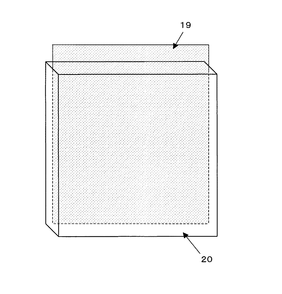
一方、比較例1、2、3の包装袋は袋の内面から溶出された個々のアウトイオン量および袋の内表面に付着しているパーティクル数が非常に多いことが分かった。比較例1および2は、総アウトガス量も1500ng/cm2を超える結果となった。比較例4は接着剤由来と推定される溶出Sn、Si量が多く、環状シロキサン量も多いという結果となった。また、アウトガス分析において、比較例2、3、4の包装袋からはシーラントに添加されている酸化防止剤であるブチルヒドロキシトルエンが検出された。 On the other hand, it was found that the packaging bags of Comparative Examples 1, 2, and 3 had an extremely large amount of individual out ions eluted from the inner surface of the bag and the number of particles adhering to the inner surface of the bag. In Comparative Examples 1 and 2, the total outgas amount exceeded 1500 ng / cm 2 . In Comparative Example 4, the amount of eluted Sn and Si estimated to be derived from the adhesive was large, and the amount of cyclic siloxane was also large. In the outgas analysis, butylhydroxytoluene, which is an antioxidant added to the sealant, was detected from the packaging bags of Comparative Examples 2, 3, and 4.
実施例1〜5、比較例1〜4の包装袋について、水蒸気透過率を測定した。その結果を表4に示す。水蒸気透過率はモコン法を用いて測定し、測定条件は40℃−90%R.H.である。 About the packaging bag of Examples 1-5 and Comparative Examples 1-4, the water-vapor-permeation rate was measured. The results are shown in Table 4. The water vapor transmission rate was measured using the Mocon method, and the measurement conditions were 40 ° C.-90% R.D. H. It is.
実施例1〜5において、シーラント面に添加剤無添加のLDPE樹脂を用い、かつ加工時の環境をクリーンにすることにより、もしくはインフレーション成形を採用することにより、コンタミネーションを防ぐことが可能であり、アウトイオン、溶出Sn、溶出Si、パーティクル、アウトガスが少ない、つまりクリーン性が非常に高い包装袋が得られる。また、蒸着フィルムを用いることにより、高い水蒸気バリア性が付与される。 In Examples 1 to 5, it is possible to prevent contamination by using an LDPE resin without additives on the sealant surface and cleaning the environment during processing, or by adopting inflation molding. A packaging bag with little oution, elution Sn, elution Si, particles, and outgas, that is, a very high cleanliness can be obtained. Moreover, high water vapor | steam barrier property is provided by using a vapor deposition film.
また、シリコンウエハー、IC、LSI等の半導体製品、コンピューター周辺装置の記憶装置であるFDD、光磁気ディスクドライブ、HDD、MRヘッド等、極微小、極微量の汚染物をも嫌う電子部品を、クリーンな環境下にて本発明の包装袋で包装することにより、電子部品包装体として与えることも可能である。 In addition, clean electronic components that dislike extremely small and trace amounts of contaminants such as semiconductor products such as silicon wafers, ICs, LSIs, FDDs that are storage devices for computer peripheral devices, magneto-optical disk drives, HDDs, MR heads, etc. By packaging with the packaging bag of the present invention in a simple environment, it can be provided as an electronic component package.
(b)はチューブ状シーラントを使用した積層体の側断面図の一例である。
10 シーラントフィルムの巻取り
11、12 シーラント
13 接着剤層
14 蒸着フィルム基材層
15、16 蒸着フィルム(ガスバリア層)
17 接着剤層
18 ナイロンフィルム層
19 多層クリーンフィルム三方シール袋
20 LPC用ボックス
A 蒸着薄膜層
B 被膜層
C 蒸着薄膜層
D 被膜層
DESCRIPTION OF
17
Claims (4)
Priority Applications (1)
| Application Number | Priority Date | Filing Date | Title |
|---|---|---|---|
| JP2004119910A JP2005298037A (en) | 2004-04-15 | 2004-04-15 | Packaging bag and electronic component package using the same |
Applications Claiming Priority (1)
| Application Number | Priority Date | Filing Date | Title |
|---|---|---|---|
| JP2004119910A JP2005298037A (en) | 2004-04-15 | 2004-04-15 | Packaging bag and electronic component package using the same |
Publications (1)
| Publication Number | Publication Date |
|---|---|
| JP2005298037A true JP2005298037A (en) | 2005-10-27 |
Family
ID=35330061
Family Applications (1)
| Application Number | Title | Priority Date | Filing Date |
|---|---|---|---|
| JP2004119910A Pending JP2005298037A (en) | 2004-04-15 | 2004-04-15 | Packaging bag and electronic component package using the same |
Country Status (1)
| Country | Link |
|---|---|
| JP (1) | JP2005298037A (en) |
Cited By (5)
| Publication number | Priority date | Publication date | Assignee | Title |
|---|---|---|---|---|
| JP2007223661A (en) * | 2006-02-27 | 2007-09-06 | Naikai Kigyo Kk | Inner bag for flexible container, manufacturing method thereof and flexible container |
| JP2012208158A (en) * | 2011-03-29 | 2012-10-25 | Shin Etsu Chem Co Ltd | Method for storing pellicle |
| WO2013136989A1 (en) * | 2012-03-13 | 2013-09-19 | 株式会社神戸製鋼所 | Coated-electrode packaging material and packaged article |
| CN113484446A (en) * | 2021-08-04 | 2021-10-08 | 上海富乐德智能科技发展有限公司 | Method for testing micro-pollution on surface of packaging bag for clean room |
| CN117944995A (en) * | 2019-08-30 | 2024-04-30 | 大日本印刷株式会社 | Silicon material transport bag and silicon material package |
Citations (3)
| Publication number | Priority date | Publication date | Assignee | Title |
|---|---|---|---|---|
| JPH07330039A (en) * | 1994-06-09 | 1995-12-19 | Dainippon Printing Co Ltd | Closed bag |
| JPH08216325A (en) * | 1995-02-13 | 1996-08-27 | Toppan Printing Co Ltd | Laminated material having vapor deposition layer, and container using this laminated material |
| JP2003147094A (en) * | 2001-08-30 | 2003-05-21 | Toppan Printing Co Ltd | Clean film and its laminate |
-
2004
- 2004-04-15 JP JP2004119910A patent/JP2005298037A/en active Pending
Patent Citations (3)
| Publication number | Priority date | Publication date | Assignee | Title |
|---|---|---|---|---|
| JPH07330039A (en) * | 1994-06-09 | 1995-12-19 | Dainippon Printing Co Ltd | Closed bag |
| JPH08216325A (en) * | 1995-02-13 | 1996-08-27 | Toppan Printing Co Ltd | Laminated material having vapor deposition layer, and container using this laminated material |
| JP2003147094A (en) * | 2001-08-30 | 2003-05-21 | Toppan Printing Co Ltd | Clean film and its laminate |
Cited By (8)
| Publication number | Priority date | Publication date | Assignee | Title |
|---|---|---|---|---|
| JP2007223661A (en) * | 2006-02-27 | 2007-09-06 | Naikai Kigyo Kk | Inner bag for flexible container, manufacturing method thereof and flexible container |
| JP2012208158A (en) * | 2011-03-29 | 2012-10-25 | Shin Etsu Chem Co Ltd | Method for storing pellicle |
| WO2013136989A1 (en) * | 2012-03-13 | 2013-09-19 | 株式会社神戸製鋼所 | Coated-electrode packaging material and packaged article |
| JP2013189220A (en) * | 2012-03-13 | 2013-09-26 | Kobe Steel Ltd | Coated-electrode packaging material and packaged article |
| CN104169193A (en) * | 2012-03-13 | 2014-11-26 | 株式会社神户制钢所 | Coated-electrode packaging material and packaged article |
| CN117944995A (en) * | 2019-08-30 | 2024-04-30 | 大日本印刷株式会社 | Silicon material transport bag and silicon material package |
| CN117944995B (en) * | 2019-08-30 | 2026-07-14 | 大日本印刷株式会社 | Transport bag for silicon material and package body for silicon material |
| CN113484446A (en) * | 2021-08-04 | 2021-10-08 | 上海富乐德智能科技发展有限公司 | Method for testing micro-pollution on surface of packaging bag for clean room |
Similar Documents
| Publication | Publication Date | Title |
|---|---|---|
| US5100720A (en) | Laminated film having gas barrier properties | |
| JP6210145B2 (en) | Packaging container | |
| TW200831426A (en) | Methods for protecting glass | |
| JPWO2015037612A1 (en) | Absorbent laminate provided with absorbent film, electronic device including the same, and manufacturing method thereof | |
| JP2006096851A (en) | Clean film and packaging bag using the same | |
| JP2003147094A (en) | Clean film and its laminate | |
| JP6648806B2 (en) | Hygroscopic easy peeling package | |
| US20200147584A1 (en) | Silica powder storage package, and test kit using this | |
| JP2003177120A (en) | Out-ion analysis method, particle or eluate measurement method, and clean film and laminate thereof | |
| WO2020175505A1 (en) | Gas barrier structure and film laminate | |
| CN107405899A (en) | Laminated body for heat sealing | |
| JP7419664B2 (en) | Deodorizing PTP packaging | |
| JP2005062118A (en) | Nonvolatile residue measurement method for film | |
| JP2024083410A (en) | Moisture absorbing transparent laminate | |
| WO2020175503A1 (en) | Vacuum insulating material | |
| JP7275502B2 (en) | Deodorant laminate for packaging liquid contents | |
| JPH06100042A (en) | Oxygen barrier laminate | |
| JP2020175936A (en) | Absorbent transparent lid material | |
| JP7585631B2 (en) | Ethylene gas adsorbent | |
| JP2020175935A (en) | Blister pack with contents | |
| JP7255279B2 (en) | deodorant laminate | |
| JP2008195447A (en) | Packaging film excellent in gas barrier properties | |
| WO2013141918A1 (en) | Metallized films and methods of making metallized films | |
| JPH0562065B2 (en) | ||
| JP2021147086A (en) | Package |
Legal Events
| Date | Code | Title | Description |
|---|---|---|---|
| A621 | Written request for application examination |
Free format text: JAPANESE INTERMEDIATE CODE: A621 Effective date: 20070323 |
|
| A977 | Report on retrieval |
Free format text: JAPANESE INTERMEDIATE CODE: A971007 Effective date: 20100118 |
|
| A131 | Notification of reasons for refusal |
Free format text: JAPANESE INTERMEDIATE CODE: A131 Effective date: 20100209 |
|
| A521 | Written amendment |
Free format text: JAPANESE INTERMEDIATE CODE: A523 Effective date: 20100408 |
|
| A131 | Notification of reasons for refusal |
Free format text: JAPANESE INTERMEDIATE CODE: A131 Effective date: 20101019 |
|
| A521 | Written amendment |
Free format text: JAPANESE INTERMEDIATE CODE: A523 Effective date: 20101214 |
|
| A02 | Decision of refusal |
Free format text: JAPANESE INTERMEDIATE CODE: A02 Effective date: 20110531 |