JP2005297970A - Breathable substrate container - Google Patents
Breathable substrate container Download PDFInfo
- Publication number
- JP2005297970A JP2005297970A JP2004112153A JP2004112153A JP2005297970A JP 2005297970 A JP2005297970 A JP 2005297970A JP 2004112153 A JP2004112153 A JP 2004112153A JP 2004112153 A JP2004112153 A JP 2004112153A JP 2005297970 A JP2005297970 A JP 2005297970A
- Authority
- JP
- Japan
- Prior art keywords
- base material
- container
- thermoplastic sheet
- flange
- breathable
- Prior art date
- Legal status (The legal status is an assumption and is not a legal conclusion. Google has not performed a legal analysis and makes no representation as to the accuracy of the status listed.)
- Pending
Links
Images


Landscapes
- Details Of Rigid Or Semi-Rigid Containers (AREA)
- Packages (AREA)
- Wrappers (AREA)
Abstract
【課題】基材の開口端部において、水分に対する高い耐浸透性と、基材と熱可塑性シートとが剥がれ難く、消費者が触れても違和感なく、周囲に引っ掛かりにくい形状に成形した通気性基材容器を提供する。
【解決手段】通気性基材Bの少なくとも凹部側表面に熱可塑性シートS11がラミネート加工されて成る容器において、当該容器の開口端部B3における外表面が熱可塑性シートS11で被覆されていることを特徴とする、通気性基材容器。
【選択図】図13[PROBLEMS] To provide a high permeability resistance to moisture at an opening end of a base material, a base material and a thermoplastic sheet that do not easily peel off, a sense of incongruity even when touched by a consumer, and a breathable base formed into a shape that is difficult to catch around. Providing a material container.
In a container formed by laminating a thermoplastic sheet S11 on at least the concave side surface of a breathable base material B, the outer surface at the opening end B3 of the container is covered with the thermoplastic sheet S11. A breathable base material container.
[Selection] Figure 13
Description
本発明は、主に食品用に供され通気性を有する基材から成る、通気性基材容器に関する。 The present invention relates to a breathable substrate container mainly made of food and made of a breathable substrate.
従来、食品用容器は、コストの安さ、成形のし易さ、耐久性、密封性、水分の耐浸透性等の種々の優れた特性を併せ持つ、プラスチック製のものが、特に液体や、汁物等の水分の多い食品用として多用されていた。
しかし、近年、一部の消費者の間では、健康志向の高まりや、自然環境への配慮などから上記したようなプラスチック製の食品用容器を敬遠する流れがあった。即ち、プラスチック製の食品用容器では、廃棄物処理等が問題視されている。
Conventionally, food containers are made of plastics having various excellent characteristics such as low cost, ease of molding, durability, sealability, moisture penetration resistance, etc., especially liquids, soups, etc. It was widely used for foods with high moisture content.
However, in recent years, some consumers have refrained from using plastic food containers such as those described above because of increased health consciousness and consideration for the natural environment. In other words, waste disposal and the like are regarded as problems in plastic food containers.
一方、例えば駅弁の外装箱など、主に固形物食品用の比較的簡易な容器として、紙製の食品用容器が従来より知られていた。こうした紙製のものは、上記したプラスチック製の食品用容器と異なり、廃棄処理が容易である等、環境負荷が少ないという利点があるが、反面、その素材としての性質上、水分の耐浸透性が低いとか、強度が不足している等の欠点があるため、固形物食品用における比較的簡易な容器等、その用途は限定的なものとならざるを得なかった。
しかし、近年の製造技術の進歩により、こうした紙製の基材表面に、樹脂シートをラミネート加工することで、水分に対する高い耐浸透性を得ることが可能となってきた。例えば、予め所望の容器形状に加工した紙製の基材に対し、その内側表面に真空成形、或いは圧空成形によりシート状の樹脂フィルムを積層接着することにより行われる方法が挙げられる。
On the other hand, paper food containers have been conventionally known as relatively simple containers mainly for solid foods, such as ekiben exterior boxes. Unlike the plastic food containers described above, these paper-made ones have the advantage of low environmental impact, such as being easy to dispose of. However, on the other hand, due to the nature of the materials, they are resistant to moisture penetration. However, its use such as a relatively simple container for solid foods has to be limited.
However, due to recent advances in manufacturing technology, it has become possible to obtain high penetration resistance to moisture by laminating a resin sheet on the surface of such a paper base material. For example, there is a method performed by laminating and bonding a sheet-like resin film on the inner surface of a paper base material that has been processed into a desired container shape in advance by vacuum forming or pressure forming.
このようなラミネート加工された紙製の食品用容器は、従来の紙製のものよりも水分の耐浸透性が高いのは勿論、高い密封性と、一定の強度を併せ持ち、液体、汁物、水分含有率の高い食品、あるいはたれ付きの食品等、その食品形態を問わず、内容物の高い保存性と耐久性を得ることが可能となっている。
こうした優れた特徴から、紙製の食品用容器が見直されつつあり、ラミネート加工技術の向上に伴って、その用途を広げるに至っている。
Such a laminated paper food container has a high water tightness and a certain strength as well as a high moisture penetration resistance compared to conventional paper ones. Regardless of the form of the food, such as food with a high content or food with sauce, it is possible to obtain high storage stability and durability of the contents.
Because of these excellent features, paper food containers are being reviewed, and the use of the containers has been expanded as the laminating technology is improved.
しかしながら、前記したような紙製の食品用容器には、以下のような問題があった。
即ち、予め所望の形状の凹部を有するように成形加工された紙製の基材に、例えば真空成形により、樹脂製の熱可塑性シートをラミネート加工した際、その開口端部に位置する部分をトリミングするのであるが、そのトリミング形態には以下に示すような2種類があった。
However, the paper food containers as described above have the following problems.
That is, when a resin-made thermoplastic sheet is laminated to a paper base material that has been molded so as to have a recess having a desired shape in advance, for example, by vacuum forming, the portion located at the opening end is trimmed. However, there are two types of trimming modes as shown below.
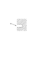
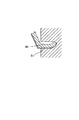
1つは、図21〜図22に示すように、基材フランジB3端部の側面までクランク状に被覆された熱可塑性シートS11を、基材フランジB3端部において、当該基材フランジ3端部ごとトリミングする方法である。
もう1つは、図23〜図24に示すように、基材フランジB3端部の側面までクランク状に被覆された熱可塑性シートS11のみを、基材フランジB3端部よりも外方でトリミングするする方法である。
As shown in FIG. 21 to FIG. 22, one is that the thermoplastic sheet S11 coated in a crank shape up to the side surface of the base flange B3 end is attached to the end of the
23. As shown in FIGS. 23 to 24, only the thermoplastic sheet S11 covered in a crank shape up to the side surface of the end portion of the base flange B3 is trimmed outward from the end portion of the base flange B3. It is a method to do.
前者の方法の場合、トリミングした断面における基材は、熱可塑性シートS11に被覆されておらず、露出することになる。この場合、食品用容器として例えばインスタントカップ麺等に用いられるような場合、前記フランジB3端部を介して、汁を消費者がすすることがあり、その際、被覆されていない基材断面から内容物が浸透してしまうおそれがあった。その結果、容器強度が低下したり、消費者に不快感を与えることがあった。 In the former method, the base material in the trimmed cross section is not covered with the thermoplastic sheet S11 and is exposed. In this case, when used as a food container, for example, for instant cup noodles, etc., the consumer may sip the juice through the end of the flange B3. There was a risk that the contents would permeate. As a result, the container strength may be reduced or the consumer may be uncomfortable.
一方、後者の方法の場合、前者の場合と異なって基材フランジB3端部の断面は熱可塑性シートS11で被覆されているので、断面自体からの内容物の浸透の浸透のおそれはないが、熱可塑性シートS11のみが、基材フランジB3端部よりも外方に突出することとなるため、前記のような消費者が汁をすする場合に、飲みにくかったり、消費者に不快感を与えてしまうおそれがあった。 On the other hand, in the latter method, unlike the former case, the cross section of the end portion of the base flange B3 is covered with the thermoplastic sheet S11, so there is no fear of penetration of the content from the cross section itself, Since only the thermoplastic sheet S11 protrudes outward from the end portion of the base flange B3, it is difficult to drink or unpleasant to the consumer when the consumer sips juice. There was a risk of it.
又、基材フランジB3端部の裏面側には熱可塑性シートは被覆されないため、フランジ端部を介して汁を消費者がすするような場合に、依然として、内容物が浸透してしまうおそれがあった。
更に、熱可塑性シートS11のみが外方に突出しているため、基材フランジB3との間が剥がれ易いという問題も生じていた。
更に、容器を梱包搬送するような場合に、熱可塑性シートS11のみが外方に突出しているため、周囲に引っ掛かり易く、特にダンボール箱内への出し入れ等の作業性の面で問題があった。
In addition, since the thermoplastic sheet is not coated on the back side of the end portion of the base flange B3, the contents may still permeate when the consumer squeezes the juice through the end of the flange. there were.
Furthermore, since only the thermoplastic sheet S11 protrudes outward, there is a problem that it is easy to peel off from the base flange B3.
Further, when the container is packed and conveyed, only the thermoplastic sheet S11 protrudes outward, so that it is easily caught around, and there is a problem in terms of workability such as taking in and out of the cardboard box.
尚、こうした諸問題は、基材の材質が紙である場合のみならず、通気性を有する、パルプモールド、でんぷん、或いはでんぷん発泡体を組成とする生分解性素材、或いは多孔性金属などの場合でも同様であった。特に、発泡体の場合は切断面において個々の発泡体が切断されて吸水性が格段に向上し、露出していると知るなどを吸収してしまう。また、唇が触れたときの感覚もすこぶる悪くなる。 These problems are not only caused when the base material is paper, but also when there is a breathable biodegradable material composed of pulp mold, starch, or starch foam, or porous metal. But it was the same. In particular, in the case of a foam, each foam is cut at the cut surface, the water absorption is remarkably improved, and it is known that it is exposed. Also, the feeling when the lips touch is much worse.
本願発明は上記課題に鑑みてなされたもので、基材の開口端部において、水分に対する高い耐浸透性と、基材と熱可塑性シートとが剥がれ難く、消費者が触れても違和感なく、周囲に引っ掛かりにくい形状に成形した通気性基材容器を提供することを目的とする。 The present invention has been made in view of the above problems, and at the opening end of the base material, high permeation resistance to moisture, the base material and the thermoplastic sheet are difficult to peel off, and there is no sense of discomfort even when touched by the consumer. An object of the present invention is to provide a breathable base material container that is molded into a shape that is difficult to be caught on.
上記問題を解決する為に請求項1に記載の発明は、通気性基材の少なくとも凹部側表面に熱可塑性シートがラミネート加工されて成る容器において、当該容器の開口端部における外表面が熱可塑性シートで被覆されている構成としている。
上記のように構成した請求項1に記載の発明によれば、容器の開口端部における外表面が熱可塑性シートで被覆され、通気性基材が水分に直接晒されない。熱可塑性シートの外方への突出も無い。
In order to solve the above problem, the invention according to
According to the invention described in
請求項2に記載の発明は、前記容器の開口端部は、トリミングされた基材のフランジ状の開口端部を、当該フランジの凹部側表面からトリミング断面を経て裏側面にかけて、コ字状に、熱可塑性シートを被覆して成る構成としている。
上記のように構成した請求項2に記載の発明によれば、基材の開口端部のフランジの表面、トリミング断面、及び裏面がコ字状に熱可塑性シートで被覆され、通気性基材が水分に直接晒されない。熱可塑性シートの外方への突出も無い。
In the invention according to claim 2, the opening end portion of the container is formed in a U shape from the trimmed base material flange-shaped opening end portion to the rear side surface through the trimming cross section from the concave side surface of the flange. The structure is formed by coating a thermoplastic sheet.
According to invention of Claim 2 comprised as mentioned above, the surface of the flange of the opening edge part of a base material, a trimming cross section, and a back surface are coat | covered with the thermoplastic sheet in U shape, and a breathable base material is Not directly exposed to moisture. There is no outward protrusion of the thermoplastic sheet.
請求項3に記載の発明は、前記容器の開口端部は、トリミングされた基材のフランジ状の開口端部、及び少なくともその凹部側表面にラミネートされた熱可塑性シートを、当該熱可塑性シートが外表面に位置するようにフランジの裏面側に巻き込むカール加工を施して成る構成としている。
上記のように構成した請求項3に記載の発明によれば、基材の開口端部のフランジと、ラミネートされた熱可塑性シートがカール加工され、通気性基材が水分に直接晒されないし、熱可塑性シートの外方への突出も無い。
According to a third aspect of the present invention, the opening end of the container includes a flanged opening end of a trimmed base material, and a thermoplastic sheet laminated on at least the recess side surface. A curling process is applied to the back side of the flange so as to be located on the outer surface.
According to the invention of
請求項4に記載の発明は、前記容器の開口端部において、熱可塑性シートのラミネート端部は、前記基材表面に対し、押圧変形により潰し加工されて成る構成としている。
上記のように構成した請求項4に記載の発明によれば、熱可塑性シートのラミネート端部が基材表面に対し、潰し加工で強固に貼り付いている。
The invention according to claim 4 is configured such that at the opening end portion of the container, the laminate end portion of the thermoplastic sheet is crushed by pressing deformation on the surface of the base material.
According to the invention described in claim 4 configured as described above, the laminate end portion of the thermoplastic sheet is firmly attached to the base material surface by crushing.
請求項5に記載の発明は、前記熱可塑性シートは、その内部に、ポリ塩化ビニリデン(PVDC),エチレン酢酸ビニル共重合体(EVA),或いはエチレン・ビニルアルコール共重合体(EVOH)に代表されるガスバリア性ポリマーをガスバリア層としてインサートされ、そのトリミング断面に露出した当該ガスバリア層が押圧変形により閉塞加工されて成る構成としている。
上記のように構成した請求項5に記載の発明によれば、ガスバリア層のトリミング断面が閉塞され、ガスバリア層が外気に直接晒されない。
In the invention according to claim 5, the thermoplastic sheet is represented by polyvinylidene chloride (PVDC), ethylene vinyl acetate copolymer (EVA), or ethylene / vinyl alcohol copolymer (EVOH). The gas barrier polymer is inserted as a gas barrier layer, and the gas barrier layer exposed in the trimming section is closed by pressing deformation.
According to the invention described in claim 5 configured as described above, the trimming section of the gas barrier layer is closed, and the gas barrier layer is not directly exposed to the outside air.
請求項6に記載の発明は、通気性基材として発泡性素材から成る容器において、フランジ状の開口端部に成形時に生じたバリの切断面が、押圧変形により閉塞加工されて成る構成としている。
上記のように構成した請求項6に記載の発明によれば、バリの切断面が閉塞され、発泡開口が水分に直接晒されない。
The invention described in claim 6 is a container made of a foamable material as a breathable base material, wherein a burr cutting surface formed at the time of molding at the flange-shaped opening end is closed by pressing deformation. .
According to the invention described in claim 6 configured as described above, the cut surface of the burr is closed, and the foam opening is not directly exposed to moisture.
請求項7に記載の発明は、通気性の前記基材は、パルプモールド、紙、でんぷん、或いはでんぷん発泡体を組成とする生分解性素材、或いは多孔性金属である構成としている。
上記のように構成した請求項7に記載の発明によれば、パルプモールド、紙、でんぷん、でんぷん発泡体、或いは多孔性金属の素材が、請求項1〜請求項5に記載された各作用により、基材として有用に使用し得る。
The invention according to claim 7 is configured such that the breathable base material is a biodegradable material having a composition of pulp mold, paper, starch, or starch foam, or a porous metal.
According to invention of Claim 7 comprised as mentioned above, a pulp mold, paper, starch, a starch foam, or the raw material of a porous metal is according to each effect | action described in Claims 1-5. It can be usefully used as a substrate.
請求項8に記載の発明は、前記容器は、内容物が加熱、或いは加湯される食品用容器であり、当該加熱時、或いは加湯時に人が把持容易に断熱するのに必要な一定厚さを有する構成としている。
上記のように構成した請求項8に記載の発明によれば、断熱性を有する一定厚さの食品用容器においても、請求項1〜請求項7に記載された各作用により、有用に使用し得る。
The invention according to claim 8 is a food container in which the contents are heated or heated, and the container has a constant thickness necessary for heat insulation to be easily grasped by a person during the heating or heating. It is set as the structure which has thickness.
According to the invention described in claim 8 configured as described above, even in a food container having a certain thickness having heat insulation, it is usefully used due to each action described in
請求項1に記載の発明によれば、容器の開口端部における外表面が熱可塑性シートで被覆され、通気性基材が水分に直接晒されず、熱可塑性シートの外方への突出も無いので、容器の開口端部の水分に対する高い耐浸透性を得ることができ、当該端部に人が口をつけるような場合であっても、耐久性が低下したり違和感を与えたりすることがない。
又、容器の開口端部における熱可塑性シートが、外方に突出することが無いので、当該端部に人が口をつけるような場合であっても、違和感を与えたりすることがない上、基材と熱可塑性シートと間で剥がれ易かったり、或いは梱包作業時などで周囲に引っ掛かり易く作業性を低下させたり、といったことがない。
According to the first aspect of the present invention, the outer surface at the opening end of the container is covered with the thermoplastic sheet, the breathable base material is not directly exposed to moisture, and the thermoplastic sheet does not protrude outward. Therefore, it is possible to obtain a high permeation resistance to moisture at the opening end of the container, and even when a person puts a mouth on the end, the durability may be lowered or uncomfortable. Absent.
In addition, since the thermoplastic sheet at the opening end of the container does not protrude outward, even if a person puts a mouth on the end, it does not give a sense of incongruity. It does not easily peel off between the base material and the thermoplastic sheet, or is easily caught around during packing work, and the workability is not lowered.
請求項2に記載の発明によれば、基材の開口端部のフランジの表面、トリミング断面、及び裏面がコ字状に熱可塑性シートで被覆され、通気性基材が水分に直接晒されず、熱可塑性シートの外方への突出も無いので、容器のフランジ状の開口端部の水分に対する高い耐浸透性を得ることができ、当該端部に人が口をつけるような場合であっても、耐久性が低下したり違和感を与えたりすることがない。
又、容器のフランジ状の開口端部における熱可塑性シートが、外方に突出することが無いので、当該端部に人が口をつけるような場合であっても、違和感を与えたりすることがない上、基材と熱可塑性シートと間で剥がれ易かったり、或いは梱包作業時などで周囲に引っ掛かり易く作業性を低下させたり、といったことがない。
According to the second aspect of the present invention, the front surface, trimming cross section, and back surface of the flange at the opening end of the base material are coated with the thermoplastic sheet in a U-shape, and the breathable base material is not directly exposed to moisture. In addition, since there is no outward protrusion of the thermoplastic sheet, high penetration resistance to moisture at the flange-shaped opening end of the container can be obtained, and a person makes a mouth on the end. However, the durability does not deteriorate or give a sense of incongruity.
Moreover, since the thermoplastic sheet at the flange-shaped opening end of the container does not protrude outward, it may give a sense of incongruity even when a person puts a mouth on the end. In addition, it does not easily peel off between the base material and the thermoplastic sheet, or is easily caught around during packing work, and the workability is not lowered.
請求項3に記載の発明によれば、基材の開口端部のフランジと、ラミネートされた熱可塑性シートがカール加工され、通気性基材が水分に直接晒されず、熱可塑性シートの外方への突出も無いので、容器の開口端部の水分に対する高い耐浸透性を得ることができ、当該端部に人が口をつけるような場合であっても、耐久性が低下したり違和感を与えたりすることがない。
又、容器の開口端部における熱可塑性シートが、外方に突出することが無いので、当該端部に人が口をつけるような場合であっても、違和感を与えたりすることがない上、基材と熱可塑性シートと間で剥がれ易かったり、或いは梱包作業時などで周囲に引っ掛かり易く作業性を低下させたり、といったことがない。
更に、容器の開口端部における剛性を向上させることができる。
According to the third aspect of the present invention, the flange at the opening end of the base material and the laminated thermoplastic sheet are curled, and the breathable base material is not directly exposed to moisture. Since there is no protrusion to the container, it is possible to obtain high penetration resistance against moisture at the opening end of the container, and even when a person puts a mouth on the end, the durability is lowered or uncomfortable. There is no giving.
In addition, since the thermoplastic sheet at the opening end of the container does not protrude outward, even if a person puts a mouth on the end, it does not give a sense of incongruity. It does not easily peel off between the base material and the thermoplastic sheet, or is easily caught around during packing work, and the workability is not lowered.
Furthermore, the rigidity at the open end of the container can be improved.
請求項4に記載の発明によれば、熱可塑性シートのラミネート端部が基材表面に対し、潰し加工で強固に貼り付いているので、熱可塑性シートが基材から剥がれるのを防止し、より耐久性を高めることができる。 According to the invention described in claim 4, since the laminate end of the thermoplastic sheet is firmly attached to the surface of the base material by crushing, the thermoplastic sheet is prevented from being peeled off from the base material. Durability can be increased.
請求項5に記載の発明によれば、ガスバリア層のトリミング断面が閉塞され、ガスバリア層が外気に直接晒されないので、ガスバリア層が外気に露出してその機能低下を招くことを抑制することができる。 According to the fifth aspect of the present invention, the trimming section of the gas barrier layer is closed and the gas barrier layer is not directly exposed to the outside air, so that it is possible to suppress the gas barrier layer from being exposed to the outside air and causing its functional deterioration. .
請求項6に記載の発明によれば、バリの切断面が閉塞され、発泡開口が水分に直接晒されないので、断面における発泡開口からの水分の浸透を抑制し、高い耐浸透性を得ることができる。 According to the invention described in claim 6, since the cut surface of the burr is closed and the foaming opening is not directly exposed to moisture, it is possible to suppress the penetration of moisture from the foaming opening in the cross section and obtain high penetration resistance. it can.
請求項7に記載の発明によれば、パルプモールド、紙、でんぷん、でんぷん発泡体、或いは多孔性金属の素材が、請求項1〜請求項5に記載された各効果により、基材として有用に使用し得るので、水分に対する耐浸透性の高い、高品質の容器を提供できる。
According to the invention described in claim 7, the pulp mold, paper, starch, starch foam, or porous metal material is useful as a substrate due to the effects described in
請求項8に記載の発明によれば、断熱性を有する一定厚さの食品用容器においても、請求項1〜請求項7に記載された各効果により、有用に使用し得るので、水分に対する耐浸透性の高く、断熱性のある高品質な食品用の容器を提供できる。
According to the invention described in claim 8, since the food container having a certain thickness having heat insulation can be usefully used due to the effects described in
以下、本発明を具体化した各実施例について説明する。 Hereinafter, each embodiment embodying the present invention will be described.
本実施例においては、通気性基材容器を、例えば熱成形装置により通気性基材としての紙製の基材に熱可塑性シートをラミネートしたうえでトリミング加工して成形する例で説明する。 In the present embodiment, an example will be described in which a breathable substrate container is formed by trimming a thermoplastic sheet on a paper substrate as a breathable substrate, for example, using a thermoforming apparatus.
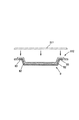
図1は、本実施例において通気性基材容器を成形する熱成形装置の概略を斜視図により示している。
熱成形装置20は、概略、ロールシート巻出装置21と、図示しないシート搬送装置、加熱装置22と、成形装置23と、トリミング装置24と、スクラップ引張装置25と、スクラップ巻取装置26とを備えるとともに、トリミング装置24から一方の側を樹脂シートにてラミネート接着された基材を取り出す基材取出装置27とから構成されている。
FIG. 1 is a perspective view schematically showing a thermoforming apparatus for forming a breathable base material container in this embodiment.
The
上記構成において、ロールシート巻出装置21にはラミネート接着に使用する熱可塑性シートロールS1が設置されており、シート搬送装置にて縁部をスパイクチェーンにて噛み込まれつつ順次必要量の熱可塑性シートS11を巻き出し可能になっている。そして、当該シート搬送装置によって巻き出された熱可塑性シートS11は、加熱装置22に搬入され、同加熱装置22に設置されているヒータなどにより輻射加熱され、熱成形によって基材にラミネート接着可能に加熱軟化される。
In the above configuration, the roll
この加熱軟化された熱可塑性シートS11は成形装置23に搬入される。加えて、この成形装置23には、基材供給装置40が接続されており、熱可塑性シートS11をラミネート接着する基材が同第1基材供給装置40によって成形装置23に搬入される。ここで、成形装置23は、概略、上部に成形用圧空箱と、下部に基材の凹部を上面にしつつ凸部を収容可能な凹部を備えた成形用金型とを有し、この成形用金型の凹部に基材の凸部を係合して、基材を成形用金型に設置する。そして、基材の上面に熱可塑性シートS11を搬入し、成形用圧空箱と成形用金型をこの熱可塑性シートS11に向かって上下動させつつ、成形用金型側から真空にて熱可塑性シートS11を引き込み基材の凹部に熱可塑性シートS11をラミネート接着させる。むろん、成形用金型側から真空にて引き込む態様に限定されるものではなく、成形用圧空箱側から圧空を吹き付けて、基材の凹部に熱可塑性シートS11をラミネート接着させてもよい。
The heat-softened thermoplastic sheet S11 is carried into the
このようにして熱可塑性シートS11が基材の凹部側にラミネート接着される。そして、熱可塑性シートS11は、基材を付加された形状にて成形シートS12を形成する。この成形シートS12は、トリミング装置24に搬入され、トリミング装置24は成形シートS12から基材部分をトリミングする。そして、成形シートS12から基材がトリミングされたスクラップシートS13は、スクラップ引張装置25によって引っ張られつつ、スクラップ巻取装置26に巻き戻されて回収されることになる。一方、トリミング装置24にて成形シートS12からトリミングされた基材は、基材取出装置27にてトリミング装置24から取り出され、後に詳述する、通気性基材容器の開口端部における外表面の熱可塑性シートによる被覆処理を行う成形端部処理装置30に移送される。
In this way, the thermoplastic sheet S11 is laminated and bonded to the concave portion side of the base material. The thermoplastic sheet S11 forms the molded sheet S12 in a shape to which a base material is added. The molded sheet S12 is carried into the
ここで、本実施例にて使用される通気性基材について説明する。
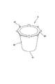
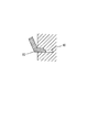
図2は、基材Bの外観を示した外観図である。同図において、基材Bは、略円状の底面B1を有するとともに、その外周から、一定の深さを有しつつ、拡開するように立ち上がる側面B2と、その上端部に、基材Bの外側に向かって水平に折り曲げられて設けられた、略円状のフランジ端部B3とが形成されて成る、例えば紙製のカップである。
Here, the air permeable base material used in the present embodiment will be described.
FIG. 2 is an external view showing the external appearance of the base material B. FIG. In the same figure, the base material B has a substantially circular bottom surface B1, a side surface B2 that rises from the outer periphery of the base material B with a certain depth, and a base material B on the upper end thereof. For example, a paper cup is formed by forming a substantially circular flange end B3 that is horizontally bent toward the outside of the sheet.
図3は、熱成形装置20にて基材Bの凹部の内側に熱可塑性シートS11をラミネート接着した場合の成形シートS12の断面図を示しているとともに、図4は、トリミング装置24にて成形シートS12をトリミングした基材Bの断面図を示している。このように、熱成形装置20においては、熱可塑性シートS11を基材Bのカップ内に入れられる内容物が触れる一方の側、すなわち、凹部の内側に対して熱成形することによって、ラミネート接着を実施し成形シートS12を形成する。そして、トリミング装置24にて、成形シートS12からフランジ部B3より一定長さの熱可塑性シート部分を残しつつトリミングを行い、上述した凹部の内側が熱可塑性シートS11にてラミネート接着された基材Bを生成する。この基材Bは、その後、成形端部処理装置30に搬入される、。
FIG. 3 shows a cross-sectional view of the molded sheet S12 when the thermoplastic sheet S11 is laminated and bonded to the inside of the concave portion of the base material B by the
尚、前記した、トリミング時にフランジ部B3端部より残す熱可塑性シートS11部分の一定長さは、フランジ部B3端部の裏面にかけてを、後述する成形端部処理装置30により被覆するのに必要十分な長さである。
The predetermined length of the thermoplastic sheet S11 portion left from the end portion of the flange portion B3 at the time of trimming is necessary and sufficient to cover the back surface of the end portion of the flange portion B3 with the molding
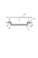
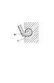
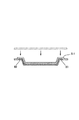
図5には、通気性基材容器の開口端部における外表面の熱可塑性シートによる被覆処理を行う成形端部処理装置30の構造を説明する概略斜視図を示す。
同図に示すように、成形端部処理装置30は、3本のローラー50がその回転軸を円周Q上に位置し且つ、互いの相対距離が同じとなるようように(即ち、正三角形の各頂点に配置されるように)、上下端が不図示の支持部材により支持されて、回動可能に並立し立設されて成る。ローラー50の配置サイズは、前記配置円Qの中心から後述する溝の基体部分52の底面までの距離が、加工する前記基材Bのフランジ部B3端部半径に略一致するように設定されている。
In FIG. 5, the schematic perspective view explaining the structure of the shaping | molding edge
As shown in the figure, the forming
各ローラー50の周面には、後述する断面形状を有する同一の溝51が、上端から下端にかけて螺旋状に配置される。各ローラー50に設けられた当該各溝51は、各ローラー50の配置される円周Qの中心に相対する溝位置(断面形状)が、常に同じとなるように配置され、不図示のインバータ駆動装置により同期回転駆動可能且つ、回転速度調節可能となっている。同期回転は、例えば、各ローラー軸に設けられたギアを、インバータ制御されるモータで一括してチェーン駆動する構成が挙げられる。
The same groove |
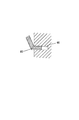
図6〜図9に示すように、本実施例における溝51は、その断面が、ローラー50の上端から下端にかけて連続的に変化するように構成されている。
即ち、溝51は、その断面形状が溝位置によらず不変な基体部分52と、当該基体部分52に隣接し、その断面形状が溝位置に応じて、連続的に変化する変体部分53との合体から成っている。前記基体部分52の形状は、その幅及び深さが前記基材Bのフランジ部B3端部の厚さ及び長さに各々略一致する矩形である。
As shown in FIGS. 6 to 9, the
That is, the
変体部分53は、前記基体部分52の上側に隣接して設けられ、少なくとも熱可塑性シートの前記延出長の長さのテーパー部54が、基体部分52の矩形奥の隣接側角部55を中心に、基体部分52深さ面との成す角度56が、溝上端側位置における図6の鈍角から、図7の直角、図8の鋭角を経て、溝下端側位置における図9の0°にかけて徐々に小さくなり、円弧軌跡を描くように連続的に変化している。
但し、この変体部分53における前記テーパー部54の変化は、後述する、3本のローラー配置円Q内に移送された基材Bが、隣接するローラー50間を回転移動する間の時間差分だけ不変とする領域を介した、階段状の変化にしている。
The
However, the change of the
即ち、基材Bのフランジ部B3の、隣接するローラー50の溝51に嵌入していた部位が回転と共に次のローラー50の溝51に到達する時間差の間、次ローラー50も回転しているので、それに伴って溝51の断面形状が大きく変わってしまうと、その部分は未加工状態となり、スムーズな加工ができない可能性がある。そこで、その間は次ローラー50が回転し、溝51位置が変わっても、断面形状を変えないことで、スムーズな加工を可能とする。
That is, because the
各ローラー50内、或いはローラー50近傍には、ローラー50の溝内温度を熱可塑性シートS11自体がその接着性を発揮し、基材に効果的に貼り付くのに必要な所定温度となるように加熱する図示しない加熱装置が設けられている。
又、各ローラー50の溝内面には、その表面に熱可塑性シートS11が貼り付くのを防止する熱可塑性シート貼り付き防止加工として、テフロン(R)等のフッ素加工が施されている。
In each
Further, fluorine processing such as Teflon (R) is applied to the inner surface of the groove of each
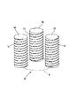
次に、基材取出装置27にてトリミング装置24から取り出され、上記のように構成される成形端部処理装置に移送された前記基材Bのフランジ部B3端部の加工処理の状態について、以下に詳述する。
即ち、基材取出装置27にて移送された基材Bは、3本の前記ローラー50間の配置円Q内に、その凹部が下方となる状態で挿入装着される。この時、各ローラー50はインバータ駆動装置により、所定速度で同期回転駆動されているため、基材Bのフランジ部B3端部は、各ローラー50の側面に螺旋状に設けられた溝51の上端開口に、3箇所で同時に嵌入する。
Next, regarding the state of the processing of the flange B3 end portion of the base material B taken out from the trimming
That is, the base material B transferred by the base material take-out
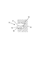
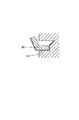
この嵌入位置での溝断面の形状は、前記した図6に示す形状となっているので、図10に示すように、基材Bのフランジ部B3の表面および側面が、溝51の前記基体部分52の下側側深さ面および底面と各々接すると同時に、熱可塑性シートS11の前記延出部分が、溝51の前記変体部分53に相対するように配置される。
この後、各ローラー50の回転と共に、溝51に嵌入しているそのフランジ部B3は、螺旋状の当該溝51に沿って移動し、それに伴って、基材Bは回転しつつ、各ローラー50間を下降していく。
Since the shape of the groove cross section at this insertion position is the shape shown in FIG. 6 described above, the surface and side surface of the flange portion B3 of the base material B are the base portion of the
Thereafter, along with the rotation of each
溝51内に嵌入したフランジ部B3の、溝51内における下端側への移動に伴い、その断面形状は前記の図6から図7へと、ローラー50間時間差に対応する前記不変領域を介しつつ連続的に変化し、それに応じて当該フランジ部B3端部における熱可塑性シートS11の前記延出部分は、前記テーパー部54によって起立され、図11に示すように、フランジ部B3の側面を垂直となるように加工される。
As the flange B3 fitted in the
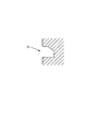
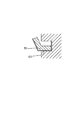
その後、更なるフランジ部B3の、溝51内における下端側への移動に伴い、その断面形状は前記の図7から図8へと連続的に変化し、それに応じて当該フランジ部B3端部における熱可塑性シートS11の前記延出部分は、前記テーパー部54によって曲げられ、図12に示すように、フランジ部B3の裏面に対し鋭角を成すように曲げ加工される。
Thereafter, as the further flange portion B3 moves toward the lower end side in the
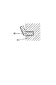
その後、フランジ部B3の、溝51内における下端側への到達に伴い、その断面形状は前記の図8から図9へと連続的に変化し、それに応じて当該フランジ部B3端部における熱可塑性シートS11の前記延出部分は、前記テーパー部54によって曲げられ、図13に示すように、フランジ部B3の裏面に密着するように曲げ加工された後、溝51の下端開口からフランジ部B3が排出され、当該フランジ部B3端部の処理が完了する。
Thereafter, as the flange portion B3 reaches the lower end side in the
前記したように、各ローラー50はその回転軸を円周Q上に位置し且つ、互いの相対距離が同じとなるようように(即ち、正三角形の各頂点に配置されるように)配置され、且つ各ローラー50の配置される円周Qの中心に相対する溝位置が、常に同じとなるように配置され、インバータ駆動装置により同期回転駆動されているので、溝51内への上記のフランジ部B3の嵌入加工の際には、1つのローラー50の溝51内を通過したフランジ部B3が次のローラー50の溝51内に到達し嵌入する時点では、基材Bの回転角度で120°分だけローラー50が回転した溝位置となっているが、その間は、隣接するローラー50の溝断面形状は不変領域にしてあるので、未加工部分を生じることはなく、スムーズで高品質な加工が可能となる。
As described above, each
以上に説明したように、本実施例においては、3本のローラー50の側面にその断面形状を変化させた溝51を螺旋状に設け、当該溝51内に基材Bのフランジ部Bを嵌入させ、溝51内に沿って回転移動させることで、フランジ部Bの裏面まで熱可塑性シートS11により被覆する。
As described above, in the present embodiment, the
これにより、従来のように基材断面が露出したり、熱可塑性シートが外方に突出するようなことがなく、水分に対する高い耐浸透性と、消費者が触れても違和感ない滑らかな端部形状を得ることができ、例えばインスタントカップ麺などに好適な容器を提供することができる。
また、周囲に引っ掛かりにくく、基材と熱可塑性シートとがはがれ難くい形状、或いは梱包等で高い作業性を得ることができる。
As a result, the cross section of the base material is not exposed and the thermoplastic sheet does not protrude outward as in the past, and it has a high penetration resistance to moisture and a smooth edge that does not feel strange even when touched by consumers. The shape can be obtained, and for example, a container suitable for instant cup noodles can be provided.
In addition, it is possible to obtain high workability with a shape that is difficult to get caught around and the base material and the thermoplastic sheet are difficult to peel off, or packaging.
尚、本願発明は本実施例の構成に限定されるものではなく、以下に列記する構成について、適宜変更可能である。
本実施例の紙製基材は、例えば、内容物が加熱、或いは加湯されるインスタント食品用容器に適用しても良い。この場合、当該加熱時、或いは加湯時に人が把持容易にするため、容器にはある程度の断熱性を持たせる必要があり、そのためには基材に一定厚さが必要となる。
In addition, this invention is not limited to the structure of a present Example, It can change suitably about the structure listed below.
The paper substrate of this embodiment may be applied to an instant food container in which the contents are heated or heated. In this case, the container needs to have a certain degree of heat insulation in order to make it easy for a person to grip when heating or heating, and for that purpose, the base material needs to have a certain thickness.
本実施形態によれば、そのような一定厚さを有する基材であっても、成形端部処理装置で容易に熱可塑性シートを開口端部に被覆し得るので、本実施形態で得られる容器は、内容物が加熱、或いは加湯されるインスタント食品用容器にも好適である。
端部処理を行う、基材のフランジにおける熱可塑性シートのトリミング時の形状は、本実施例のような、フランジ側面までクランク状に被覆された状態であるものに限定はされず、例えば、フランジ側面は被覆されずに、単にフランジ表面から外方に伸延した形状のものであってもよい。
この場合、フランジ端部の加工は、裏面よりも先に、その側面へ被覆する必要があるので、それに応じた溝の断面形状とする必要がある。
According to the present embodiment, even with a base material having such a constant thickness, the opening end can be easily coated with the thermoplastic sheet with the molded end processing apparatus, so the container obtained in the present embodiment Is also suitable for instant food containers in which the contents are heated or heated.
The shape at the time of trimming the thermoplastic sheet in the flange of the base material that performs the end treatment is not limited to the state in which the flange side surface is covered in a crank shape as in this embodiment. The side surface may not be covered but may simply be extended outward from the flange surface.
In this case, since the end of the flange needs to be coated on the side surface before the back surface, the cross-sectional shape of the groove corresponding to that needs to be covered.
具体的には、フランジ端部よりも長い深さの矩形溝を、フランジ端部表面側角に相当する位置を中心に徐々に起立させる断面変化を有する溝を設け、その後にはフランジ端部裏面側角を中心に徐々に寝かせる断面変化を有する溝を続けて設ける構成が考えられる。
螺旋状の溝の最終部分に、基材フランジ端部の幅よりも狭化した断面形状を設けることで、フランジ裏面側へ熱可塑性シートを強く圧接するようにしても良い。
Specifically, a rectangular groove having a depth longer than the flange end portion is provided with a groove having a cross-sectional change that gradually rises around a position corresponding to the flange end surface side corner, and then the flange end rear surface The structure which provides the groove | channel which has a cross-sectional change which makes it lie down centering on a side angle continuously is considered.
A thermoplastic sheet may be strongly pressed against the flange back surface side by providing a cross-sectional shape narrower than the width of the end portion of the base flange at the final portion of the spiral groove.
これによれば、熱可塑性シートを基材フランジ部分に、より強固に貼り付いた容器にすることができ、耐久性を高め、より剥がれ難くすることができる。
熱可塑性シートにおいては、その用途に応じて、ガスバリア性を持たせるために、その内部にポリ塩化ビニリデン(PVDC),エチレン酢酸ビニル共重合体(EVA),或いはエチレン・ビニルアルコール共重合体(EVOH)に代表されるガスバリア性ポリマーをガスバリア層としてインサートする場合がある。
According to this, it is possible to make the container in which the thermoplastic sheet is more firmly attached to the base flange portion, and it is possible to improve durability and make it more difficult to peel off.
In the thermoplastic sheet, in order to give a gas barrier property depending on the use, polyvinylidene chloride (PVDC), ethylene-vinyl acetate copolymer (EVA), or ethylene-vinyl alcohol copolymer (EVOH) is contained therein. ) May be inserted as a gas barrier layer.
このようなガスバリア層は、一般に、層内が外気に直接晒されると、吸湿等によりそのガスバリア機能が低下してしまう傾向がある。従って、こうしたガスバリア層がインサートされた熱可塑性シートをトリミングした場合、その端部断面においてガスバリア層が露出してしまいガスバリア層の機能低下を招くおそれがあった。 In general, when such a gas barrier layer is directly exposed to the outside air, the gas barrier function tends to deteriorate due to moisture absorption or the like. Therefore, when trimming a thermoplastic sheet in which such a gas barrier layer is inserted, the gas barrier layer is exposed at the end cross-section, and the function of the gas barrier layer may be deteriorated.
そこでこれを解決するために、溝の何れかの位置において、少なくとも熱可塑性シートの切断端部に位置する深さでの幅を、基材フランジ端部の幅よりも狭化することで、熱可塑性シートのガスバリア層が露出する端部断面を押圧変形させ、閉塞加工するような構成にしても良い。 In order to solve this problem, at any position of the groove, at least the width at the depth located at the cut end of the thermoplastic sheet is made narrower than the width of the end of the base flange. You may make it the structure which press-deforms the edge part cross section which the gas barrier layer of a plastic sheet exposes, and carries out obstruction | occlusion processing.
これによれば、熱可塑性シートの端部断面において、ガスバリア層が直接外気に晒されるのを防止し、機能低下を抑制した容器にすることができる。
尚、溝の狭化する位置は、熱可塑性シートを折り曲げる前の最初の部分で行っても良いし、或いは、折り曲げて基材フランジ裏面に貼り付けた最終の部分で行っても良い。
According to this, in the end section of the thermoplastic sheet, it is possible to prevent the gas barrier layer from being directly exposed to the outside air, and to make a container in which the function deterioration is suppressed.
In addition, the position where the groove is narrowed may be performed at an initial portion before the thermoplastic sheet is bent, or may be performed at a final portion which is bent and attached to the back surface of the base flange.
最終の部分で行う場合、狭化により、同時に基材により強固に貼り付ける効果も併せて得ることができる。
基材開口端部に対する熱可塑性シートの被覆形態は、本実施形態におけるようなコ字状には限定されず、外表面が被覆される他の種々の被覆形態であっても良い。
容器の形状は、本実施例におけるカップ形状に限定はされず、どんぶり形状、椀形状、皿形状、トレー形状等、他の種々の形状の容器が挙げられる。
容器の用途も、インスタントカップ麺に限定はされず、とうふ、こんにゃく等、食品用容器をはじめとする他の種々の用途に適用可能である。
基材の材質は紙に限定はされず、通気性を有する、パルプモールド、でんぷん、或いはでんぷん発泡体を組成とする生分解性素材、或いは多孔性金属等、他の各種の材質に適用可能である。
When it is performed in the final part, the effect of sticking firmly to the base material at the same time can be obtained by narrowing.
The coating form of the thermoplastic sheet on the opening end of the base material is not limited to the U shape as in the present embodiment, and may be various other coating forms in which the outer surface is coated.
The shape of the container is not limited to the cup shape in the present embodiment, and examples include various other shapes such as a bowl shape, a bowl shape, a dish shape, and a tray shape.
The use of the container is not limited to instant cup noodles, and can be applied to various other uses such as food containers such as tofu and konjac.
The material of the base material is not limited to paper, and can be applied to various other materials such as a biodegradable material having a breathability, pulp mold, starch, or starch foam composition, or porous metal. is there.
熱可塑性シートの材質は、例えばポリプロピレン、或いはポリエチレン等、熱可塑性であり、基材にラミネート可能な種々の材料が適用可能である。
処理を行う基材の端部形状は実施例のような水平なフランジ形状に限定はされず、例えば湾曲した端部など、他の形状であっても良い。
熱可塑性シートの基材への被覆は、本実施例では基材の凹部内側に施す例で説明したが、これに限定はされず、逆に基材の凸部外側に施すようにしても良い。この場合、基材のフランジ部を被覆するべく折り曲げる方向が逆となる。
更に、熱可塑性シートを基材の凹部側と凸部側の両方に貼り付けるようにしても良い。
The material of the thermoplastic sheet is thermoplastic, such as polypropylene or polyethylene, and various materials that can be laminated on the substrate are applicable.
The end shape of the base material to be processed is not limited to the horizontal flange shape as in the embodiment, and may be another shape such as a curved end portion.
In this embodiment, the coating of the thermoplastic sheet on the base material has been described with reference to the inside of the concave portion of the base material. However, the present invention is not limited to this. . In this case, the direction of bending to cover the flange portion of the substrate is reversed.
Furthermore, you may make it affix a thermoplastic sheet to both the recessed part side and convex part side of a base material.
本実施例においては、トリミングされた基材フランジ部B3と当該部位にラミネートされた熱可塑性シートS11とを、カール加工する実施形態について説明する。
即ち、本実施例における成形端部処理装置30は、ローラー50周面に設けられる溝51の断面形状が下記のように異なる以外は、実施例1と同様であり、その共通の構成については説明を省略する。
溝51の断面形状、及び嵌入した基材フランジ部b3を、図14〜図17に示す。
In the present embodiment, an embodiment in which the trimmed base flange portion B3 and the thermoplastic sheet S11 laminated on the portion are curled will be described.
That is, the molding
The cross-sectional shape of the
本実施例では、容器フランジ部のトリミング形態は、熱可塑性シートを容器凹部側に貼り付けた状態でその端部を、基材と熱可塑性シートごと、トリミングする。即ち、その端部断面は、基材、及び熱可塑性シートの両方が露出している。 In the present embodiment, the container flange portion is trimmed by trimming the end portion together with the base material and the thermoplastic sheet in a state where the thermoplastic sheet is attached to the container recess side. That is, both the base material and the thermoplastic sheet are exposed in the end cross section.
ローラーの一端側に位置する溝の断面形状は、図14に示すように、その幅、及び深さが、トリミングされた容器のフランジ部の厚さ、及び幅と略一致する矩形形状となっており、ローラー間に挿入装着された、前述したトリミング済みの基材フランジ部が嵌入する。
その後、溝の断面形状は図15〜図17にかけて、巻き込み方向である、基材凸方向(図面上方)の内側に向けて、徐々に巻き込むように、湾曲起立していく。尚、これら溝断面形状の変化の過程では、実施例1同様、前記の不変領域が介在し、設けられている。
As shown in FIG. 14, the cross-sectional shape of the groove located on the one end side of the roller is a rectangular shape whose width and depth substantially coincide with the thickness and width of the flange portion of the trimmed container. In addition, the trimmed substrate flange portion inserted and mounted between the rollers is inserted.
Thereafter, the cross-sectional shape of the groove rises in a curve so as to gradually wind toward the inner side of the convex direction of the base material (upward in the drawing), which is the winding direction, from FIGS. In the process of changing the groove cross-sectional shape, the invariant region is interposed and provided as in the first embodiment.
以上に説明したように、本実施例においては、実施例1と同様の3本のローラー50の側面にその断面形状をカール加工するべく変化させた溝51を螺旋状に設け、当該溝51内に基材Bのフランジ部B3を嵌入させ、溝51内に沿って回転移動させることでカール加工を行うようにした。
これにより、従来のように基材断面が露出したり、熱可塑性シートS11が外方に突出するようなことがなく、水分に対する高い耐浸透性と、消費者が触れても違和感ない滑らかな端部形状を得ることができ、例えばインスタントカップ麺などに好適な容器を提供することができる。
As described above, in the present embodiment, the
As a result, the cross section of the base material is not exposed and the thermoplastic sheet S11 does not protrude outward as in the conventional case, and has a high penetration resistance to moisture and a smooth edge that does not feel strange even when touched by the consumer. A part shape can be obtained, for example, a container suitable for instant cup noodles can be provided.
また、周囲に引っ掛かりにくく、基材と熱可塑性シートとがはがれ難くい形状、或いは梱包等で高い作業性を得ることができる。
更に、カール加工により、容器の剛性を向上させることができる。
尚、本願発明は本実施例の構成に限定されるものではなく、以下に列記する構成について、適宜変更可能である。
本実施例では、基材のフランジ部のトリミング形態を、その断面が基材と熱可塑性シートごと露出するようにしているが、これに限定はされず、例えば、実施例1のようにフランジ部の側面を被覆する状態のクランク状の熱可塑性シートをトリミングする形態であっても良い。この場合、実施例1のフランジ裏面側までの熱可塑性シートの被覆を行った後に、続けて本実施例のカール加工を施すようにしても良い。
In addition, it is possible to obtain high workability with a shape that is difficult to get caught around and the base material and the thermoplastic sheet are difficult to peel off, or packaging.
Furthermore, the rigidity of the container can be improved by curling.
In addition, this invention is not limited to the structure of a present Example, It can change suitably about the structure listed below.
In the present embodiment, the trimming form of the flange portion of the base material is such that the cross section is exposed together with the base material and the thermoplastic sheet, but is not limited to this, for example, the flange portion as in the first embodiment. A form of trimming a crank-shaped thermoplastic sheet in a state of covering the side surface of the sheet may be used. In this case, after the thermoplastic sheet covering to the flange back surface of Example 1 is performed, the curling process of this example may be performed subsequently.
更にこの場合、ロールに設ける溝の断面形状を、こうした被覆加工とカール加工とが連続して成されるように、変化させても良い。
或いは、別々のロールを用意し、順次、加工を行うようにしても良い。
上記のように、熱可塑性シートによるフランジ裏面までの被覆処理を行った後にカール加工を施せば、より一層、水分に対する耐浸透性を図ることができる。
Further, in this case, the cross-sectional shape of the groove provided in the roll may be changed so that the covering process and the curling process are continuously performed.
Alternatively, separate rolls may be prepared and processed sequentially.
As described above, if the curling process is performed after the coating process up to the flange back surface with the thermoplastic sheet, the penetration resistance against moisture can be further improved.
実施例1と共通する構成については、実施例1で列記した限定されない項目について、本実施例でも同様であり、記載を省略する。 About the structure which is common in Example 1, about the item which is not limited listed in Example 1, it is the same also in a present Example, and description is abbreviate | omitted.
本実施例においては、例えば発泡性の素材で容器を成形する場合に生じるバリをカットした際、その断面の発泡開口による水分の浸透を抑制する実施形態について説明する。 In the present embodiment, an embodiment will be described in which, for example, when a burr generated when a container is formed of a foamable material is cut, moisture permeation through the foamed opening in the cross section is suppressed.
例えばスチロール樹脂等の発泡性材料を容器の材料として成形する場合、通常、成形型内の圧力コントロールのために、圧抜き口が成形型に設けられている。従って、型から取り出した容器の成形品には、図18に示すようなバリ60が付いている。このバリ60をカットする方法として、従来はグラインダーや回転式カッターを用いる方法が一般的であった。
For example, when a foamable material such as styrene resin is molded as a container material, a pressure release port is usually provided in the mold for pressure control in the mold. Therefore, the molded product of the container taken out from the mold has a
しかし、こうした従来の方法では、材料が発泡性であるがゆえ、カットした断面に発泡開口を生じてしまうことが避けられなかった。このような開口の存在により、容器の内容物が浸透してしまうおそれがあった。その結果、容器強度が低下したり、消費者に不快感を与えることがあった。 However, in such a conventional method, since the material is foamable, it is inevitable that foamed openings are formed in the cut section. Due to the presence of such an opening, the contents of the container may permeate. As a result, the container strength may be reduced or the consumer may be uncomfortable.
本実施例では、この問題を解決した発泡性素材の容器を得るものである。
本実施例における成形端部処理装置30は、ローラー50の周面に設けられる溝51の断面形状が下記のように異なる以外は、実施例1と同様であり、その共通の構成については説明を省略する。
In the present embodiment, a container made of an expandable material that solves this problem is obtained.
The forming
図19〜図20に、本実施例におけるローラー50の断面形状、及び嵌入した発泡性容器Bのフランジ部B3を示す。
ローラー50の一端側に位置する溝51の断面形状は、図19に示すように、その幅、及び深さが、発泡性容器Bのフランジ部B3のバリ60の厚さ、及び幅と略一致する矩形形状となっており、ローラー50間に挿入装着された、基材フランジ部B3(バリ60)が嵌入する。
その後、溝の断面形状は図20にかけて、その幅が狭化されるように変化していく。
すると、それに応じて基材フランジ部B3のバリ60が厚さ方向に押圧される。この押圧により、バリ60内部の発泡は押圧閉塞される。
19 to 20 show the cross-sectional shape of the
As shown in FIG. 19, the cross-sectional shape of the
Thereafter, the cross-sectional shape of the groove changes so as to be narrowed as shown in FIG.
Accordingly, the
その後、溝より排出された、上記の閉塞されたバリ60は、ローラーに隣接する切断位置に配置された、例えばモータで駆動される不図示の切断手段としての円筒グラインダーにより、切断される。この際、バリ60は前述した通りその内部が事前に押圧閉塞されているので、その切断面には、発泡開口は存在しない。
尚、これら溝断面形状の変化の過程では、実施例1同様、前記の不変領域が介在し、設けられている。
Thereafter, the closed
In the process of changing the groove cross-sectional shape, the invariant region is interposed and provided as in the first embodiment.
以上に説明したように、本実施例においては、実施例1と同様の3本のローラー50の周面にその断面形状を、バリ60内部の発泡を押圧閉塞した後にカットするべく変化させた溝51を螺旋状に設け、当該溝51内に発泡性容器のフランジ部B3のバリ60を嵌入させ、溝51内に沿って回転移動させることでカット前に、事前の発泡開口の閉塞加工を行ってからカットを行うようにしたので、従来のグラインダーや回転式カッターを用いる方法による加工では成し得ない、フランジ部のバリの閉塞したカット処理が容易に行える。
As described above, in this embodiment, the groove whose cross-sectional shape is changed on the peripheral surface of the same three
これにより、従来のように発泡性容器のフランジ部断面に発泡開口が露出するようなことがなく、水分に対する高い耐浸透性を得ることができ、例えばインスタントカップ麺などに好適な容器を提供することができる。
尚、本願発明は本実施例の構成に限定されるものではなく、以下に列記する構成について、適宜変更可能である。
発泡性容器のフランジ部のバリの押圧閉塞後のカットは、ローラーの溝内に切断手段を設けて行うようにしても良い。
Thereby, the foaming opening is not exposed in the flange section of the foamable container as in the prior art, and high permeation resistance against moisture can be obtained. For example, a container suitable for instant cup noodles is provided. be able to.
In addition, this invention is not limited to the structure of a present Example, It can change suitably about the structure listed below.
The cut after pressing and closing the burr of the flange portion of the foamable container may be performed by providing a cutting means in the groove of the roller.
当該切断手段としては、例えば、刃状突起を装着する構成が挙げられる。
発泡性容器のフランジ部のバリを、本実施例では押圧閉塞後にカットしているが、逆にカットした後に押圧閉塞するようにしても良い。この場合、押圧閉塞する溝への発泡性容器のフランジ部の嵌入前にカット可能な位置に、前記切断手段を配置する。
Examples of the cutting means include a configuration in which a blade-like protrusion is attached.
Although the burr on the flange portion of the foamable container is cut after pressing and blocking in this embodiment, the burr may be pressed and blocked after cutting. In this case, the cutting means is disposed at a position where the flange portion of the foamable container can be cut into the groove to be pressed and closed.
或いは、事前にカット済みの容器を、その断面開口部の押圧閉塞を行うべく、ローラー間に装着して行うようにしても良い。
実施例1と共通する構成については、実施例1で列記した限定されない項目について、本実施例でも同様であり、記載を省略する。
Alternatively, a container that has been cut in advance may be mounted between rollers so as to close the cross-sectional opening.
About the structure which is common in Example 1, about the item which is not limited listed in Example 1, it is the same also in a present Example, and description is abbreviate | omitted.
以下に、「特許請求の範囲」に記載した以外で、以上に記載した実施例から把握できる発明(技術的思想)を記載する。
(1)前記熱可塑性シートは、ポリプロピレン、或いはポリエチレンであることを特徴とする、請求項1〜請求項8に記載の通気性基材容器。
(2)前記容器の形状は、カップ形状、どんぶり形状、椀形状、皿形状、或いはトレー形状であることを特徴とする、請求項1〜請求項8に記載の通気性基材容器。
In the following, inventions (technical ideas) that can be grasped from the above-described embodiments other than those described in “Claims” are described.
(1) The breathable substrate container according to any one of
(2) The breathable base material container according to any one of
基材表面に熱可塑性シートをラミネートする容器において、水分の高い耐浸透性を有する開口端部を有し、特に水分を有する食品用容器に好適な通気性基材容器を提供する。 A container for laminating a thermoplastic sheet on the surface of a substrate has an open end portion having high moisture penetration resistance, and provides a breathable substrate container particularly suitable for a food container having moisture.
60…成形バリ
B…基材
B3…開口端部としての基材フランジ
S11…熱可塑性シート
60 ... molding burr B ... base material B3 ... base material flange as opening end S11 ... thermoplastic sheet
Claims (8)
Priority Applications (1)
| Application Number | Priority Date | Filing Date | Title |
|---|---|---|---|
| JP2004112153A JP2005297970A (en) | 2004-04-06 | 2004-04-06 | Breathable substrate container |
Applications Claiming Priority (1)
| Application Number | Priority Date | Filing Date | Title |
|---|---|---|---|
| JP2004112153A JP2005297970A (en) | 2004-04-06 | 2004-04-06 | Breathable substrate container |
Publications (1)
| Publication Number | Publication Date |
|---|---|
| JP2005297970A true JP2005297970A (en) | 2005-10-27 |
Family
ID=35329997
Family Applications (1)
| Application Number | Title | Priority Date | Filing Date |
|---|---|---|---|
| JP2004112153A Pending JP2005297970A (en) | 2004-04-06 | 2004-04-06 | Breathable substrate container |
Country Status (1)
| Country | Link |
|---|---|
| JP (1) | JP2005297970A (en) |
Cited By (1)
| Publication number | Priority date | Publication date | Assignee | Title |
|---|---|---|---|---|
| JP2024516590A (en) * | 2021-04-26 | 2024-04-16 | アイサパック ホールディング エスエー | Packaging and manufacturing process |
Citations (7)
| Publication number | Priority date | Publication date | Assignee | Title |
|---|---|---|---|---|
| JPS5665807U (en) * | 1979-10-29 | 1981-06-02 | ||
| JPS6089336A (en) * | 1983-10-21 | 1985-05-20 | Sekisui Plastics Co Ltd | Method of molding mouth edge section of container |
| JPH0930523A (en) * | 1995-07-18 | 1997-02-04 | Jsp Corp | Material for container and container made of the material |
| JPH10218235A (en) * | 1997-02-06 | 1998-08-18 | Dainippon Printing Co Ltd | Composite container and method for producing the same |
| JP2002363900A (en) * | 2001-04-06 | 2002-12-18 | Kao Corp | Manufacturing method of molded body with flange |
| JP2003113600A (en) * | 2001-08-03 | 2003-04-18 | Kao Corp | Pulp molded product |
| JP2004026237A (en) * | 2002-06-26 | 2004-01-29 | Nissei Co Ltd | Bio-degradable molded vessel and method for manufacturing the same |
-
2004
- 2004-04-06 JP JP2004112153A patent/JP2005297970A/en active Pending
Patent Citations (7)
| Publication number | Priority date | Publication date | Assignee | Title |
|---|---|---|---|---|
| JPS5665807U (en) * | 1979-10-29 | 1981-06-02 | ||
| JPS6089336A (en) * | 1983-10-21 | 1985-05-20 | Sekisui Plastics Co Ltd | Method of molding mouth edge section of container |
| JPH0930523A (en) * | 1995-07-18 | 1997-02-04 | Jsp Corp | Material for container and container made of the material |
| JPH10218235A (en) * | 1997-02-06 | 1998-08-18 | Dainippon Printing Co Ltd | Composite container and method for producing the same |
| JP2002363900A (en) * | 2001-04-06 | 2002-12-18 | Kao Corp | Manufacturing method of molded body with flange |
| JP2003113600A (en) * | 2001-08-03 | 2003-04-18 | Kao Corp | Pulp molded product |
| JP2004026237A (en) * | 2002-06-26 | 2004-01-29 | Nissei Co Ltd | Bio-degradable molded vessel and method for manufacturing the same |
Cited By (1)
| Publication number | Priority date | Publication date | Assignee | Title |
|---|---|---|---|---|
| JP2024516590A (en) * | 2021-04-26 | 2024-04-16 | アイサパック ホールディング エスエー | Packaging and manufacturing process |
Similar Documents
| Publication | Publication Date | Title |
|---|---|---|
| EP1904384B1 (en) | Container employing inner liner and vents for thermal insulation and methods of making same | |
| EP0952087B1 (en) | Tubular container with heat seal having an inner and outer bead and method of manufacturing said container | |
| JPWO1997034817A1 (en) | Insulating container and manufacturing method thereof | |
| US20060198972A1 (en) | Disposable Paper Eating Utensils for Catering Service | |
| JP3596681B2 (en) | Container and manufacturing method thereof | |
| EP2658786B1 (en) | Improved paper cup | |
| US8622232B2 (en) | Method of making a container employing inner liner and vents for thermal insulation | |
| EP3855983A1 (en) | Drinking straw | |
| US20060196923A1 (en) | Insulated container | |
| JP2004090929A (en) | Insulated paper container | |
| CN213733700U (en) | Edge-seepage-preventing paper container blank and paper container thereof | |
| JP2005297970A (en) | Breathable substrate container | |
| JP2005082165A (en) | Heat insulating paper-made container | |
| JP2004106918A (en) | Paper overcap | |
| JP2005053554A (en) | Drawing molded sealed paper container | |
| JP2005271465A (en) | Container forming end processing apparatus and container forming end processing method | |
| WO2017029997A1 (en) | Paper container and method for producing same | |
| JP2012091808A (en) | Paper container in shape of bowl | |
| JP2512641Y2 (en) | Cup made of expanded polypropylene | |
| JP2006341911A (en) | Bowl type paper container | |
| JPH09168381A (en) | Portable ashtray and manufacturing method | |
| CA2753242C (en) | Method of making a container employing inner liner and vents for thermal insulation | |
| JPH09104066A (en) | Styrenic resin foam sheet container having curled mouth and method for producing the same | |
| JP2556395B2 (en) | Container manufacturing method | |
| JP2003231515A (en) | Liquid filling container |
Legal Events
| Date | Code | Title | Description |
|---|---|---|---|
| A621 | Written request for application examination |
Free format text: JAPANESE INTERMEDIATE CODE: A621 Effective date: 20070221 |
|
| A977 | Report on retrieval |
Free format text: JAPANESE INTERMEDIATE CODE: A971007 Effective date: 20080911 |
|
| A131 | Notification of reasons for refusal |
Free format text: JAPANESE INTERMEDIATE CODE: A131 Effective date: 20080917 |
|
| A02 | Decision of refusal |
Free format text: JAPANESE INTERMEDIATE CODE: A02 Effective date: 20090204 |