JP2005297951A - Method for heating fuel oil in fuel oil storage tank - Google Patents
Method for heating fuel oil in fuel oil storage tank Download PDFInfo
- Publication number
- JP2005297951A JP2005297951A JP2005065312A JP2005065312A JP2005297951A JP 2005297951 A JP2005297951 A JP 2005297951A JP 2005065312 A JP2005065312 A JP 2005065312A JP 2005065312 A JP2005065312 A JP 2005065312A JP 2005297951 A JP2005297951 A JP 2005297951A
- Authority
- JP
- Japan
- Prior art keywords
- fuel oil
- storage tank
- oil storage
- box
- heating
- Prior art date
- Legal status (The legal status is an assumption and is not a legal conclusion. Google has not performed a legal analysis and makes no representation as to the accuracy of the status listed.)
- Granted
Links
- 239000000295 fuel oil Substances 0.000 title claims abstract description 175
- 238000010438 heat treatment Methods 0.000 title claims abstract description 31
- 238000000034 method Methods 0.000 title claims abstract description 16
- 238000005192 partition Methods 0.000 claims abstract description 14
- 239000003921 oil Substances 0.000 claims description 6
- 239000000446 fuel Substances 0.000 claims description 3
- 238000009792 diffusion process Methods 0.000 abstract description 2
- 238000010792 warming Methods 0.000 abstract 2
- 239000013535 sea water Substances 0.000 description 2
- 238000005352 clarification Methods 0.000 description 1
- 238000010276 construction Methods 0.000 description 1
- 239000002828 fuel tank Substances 0.000 description 1
- 230000005484 gravity Effects 0.000 description 1
- 239000010762 marine fuel oil Substances 0.000 description 1
- 238000000926 separation method Methods 0.000 description 1
- XLYOFNOQVPJJNP-UHFFFAOYSA-N water Substances O XLYOFNOQVPJJNP-UHFFFAOYSA-N 0.000 description 1
Images
Classifications
-
- B—PERFORMING OPERATIONS; TRANSPORTING
- B63—SHIPS OR OTHER WATERBORNE VESSELS; RELATED EQUIPMENT
- B63B—SHIPS OR OTHER WATERBORNE VESSELS; EQUIPMENT FOR SHIPPING
- B63B17/00—Vessels parts, details, or accessories, not otherwise provided for
- B63B17/0027—Tanks for fuel or the like ; Accessories therefor, e.g. tank filler caps
-
- B—PERFORMING OPERATIONS; TRANSPORTING
- B63—SHIPS OR OTHER WATERBORNE VESSELS; RELATED EQUIPMENT
- B63B—SHIPS OR OTHER WATERBORNE VESSELS; EQUIPMENT FOR SHIPPING
- B63B11/00—Interior subdivision of hulls
- B63B11/04—Constructional features of bunkers, e.g. structural fuel tanks, or ballast tanks, e.g. with elastic walls
-
- B—PERFORMING OPERATIONS; TRANSPORTING
- B63—SHIPS OR OTHER WATERBORNE VESSELS; RELATED EQUIPMENT
- B63H—MARINE PROPULSION OR STEERING
- B63H21/00—Use of propulsion power plant or units on vessels
- B63H21/38—Apparatus or methods specially adapted for use on marine vessels, for handling power plant or unit liquids, e.g. lubricants, coolants, fuels or the like
-
- B—PERFORMING OPERATIONS; TRANSPORTING
- B63—SHIPS OR OTHER WATERBORNE VESSELS; RELATED EQUIPMENT
- B63J—AUXILIARIES ON VESSELS
- B63J2/00—Arrangements of ventilation, heating, cooling, or air-conditioning
- B63J2/12—Heating; Cooling
-
- F—MECHANICAL ENGINEERING; LIGHTING; HEATING; WEAPONS; BLASTING
- F04—POSITIVE - DISPLACEMENT MACHINES FOR LIQUIDS; PUMPS FOR LIQUIDS OR ELASTIC FLUIDS
- F04D—NON-POSITIVE-DISPLACEMENT PUMPS
- F04D29/00—Details, component parts, or accessories
- F04D29/007—Details, component parts, or accessories especially adapted for liquid pumps
-
- F—MECHANICAL ENGINEERING; LIGHTING; HEATING; WEAPONS; BLASTING
- F04—POSITIVE - DISPLACEMENT MACHINES FOR LIQUIDS; PUMPS FOR LIQUIDS OR ELASTIC FLUIDS
- F04D—NON-POSITIVE-DISPLACEMENT PUMPS
- F04D29/00—Details, component parts, or accessories
- F04D29/40—Casings; Connections of working fluid
- F04D29/42—Casings; Connections of working fluid for radial or helico-centrifugal pumps
- F04D29/44—Fluid-guiding means, e.g. diffusers
-
- B—PERFORMING OPERATIONS; TRANSPORTING
- B60—VEHICLES IN GENERAL
- B60K—ARRANGEMENT OR MOUNTING OF PROPULSION UNITS OR OF TRANSMISSIONS IN VEHICLES; ARRANGEMENT OR MOUNTING OF PLURAL DIVERSE PRIME-MOVERS IN VEHICLES; AUXILIARY DRIVES FOR VEHICLES; INSTRUMENTATION OR DASHBOARDS FOR VEHICLES; ARRANGEMENTS IN CONNECTION WITH COOLING, AIR INTAKE, GAS EXHAUST OR FUEL SUPPLY OF PROPULSION UNITS IN VEHICLES
- B60K15/00—Arrangement in connection with fuel supply of combustion engines or other fuel consuming energy converters, e.g. fuel cells; Mounting or construction of fuel tanks
- B60K15/03—Fuel tanks
- B60K15/077—Fuel tanks with means modifying or controlling distribution or motion of fuel, e.g. to prevent noise, surge, splash or fuel starvation
-
- Y—GENERAL TAGGING OF NEW TECHNOLOGICAL DEVELOPMENTS; GENERAL TAGGING OF CROSS-SECTIONAL TECHNOLOGIES SPANNING OVER SEVERAL SECTIONS OF THE IPC; TECHNICAL SUBJECTS COVERED BY FORMER USPC CROSS-REFERENCE ART COLLECTIONS [XRACs] AND DIGESTS
- Y10—TECHNICAL SUBJECTS COVERED BY FORMER USPC
- Y10S—TECHNICAL SUBJECTS COVERED BY FORMER USPC CROSS-REFERENCE ART COLLECTIONS [XRACs] AND DIGESTS
- Y10S417/00—Pumps
Landscapes
- Engineering & Computer Science (AREA)
- Mechanical Engineering (AREA)
- Chemical & Material Sciences (AREA)
- Combustion & Propulsion (AREA)
- Ocean & Marine Engineering (AREA)
- General Engineering & Computer Science (AREA)
- Loading And Unloading Of Fuel Tanks Or Ships (AREA)
- Cooling, Air Intake And Gas Exhaust, And Fuel Tank Arrangements In Propulsion Units (AREA)
- Feeding And Controlling Fuel (AREA)
- Lubrication Of Internal Combustion Engines (AREA)
Abstract
Description
本発明は船舶等における燃料油貯蔵タンク中の燃料油の加熱方法に係り、詳細には、澄タンクで加熱された燃料油を澄タンクやサービスタンクから貯蔵タンクに流下混合して該タンク中の燃料油を所望温度に加温する加熱方法に係り、特にタンク中の燃料油の加温効率を部分的に向上させる燃料油貯蔵タンク中の燃料油の加熱方法に関する。 The present invention relates to a method for heating fuel oil in a fuel oil storage tank in a ship or the like. Specifically, fuel oil heated in a clear tank flows down from a clear tank or a service tank to a storage tank and is mixed in the tank. The present invention relates to a heating method for heating fuel oil to a desired temperature, and more particularly to a heating method for fuel oil in a fuel oil storage tank that partially improves the heating efficiency of the fuel oil in the tank.
船舶等において、燃料油を機関に供給する際に、通常、燃料油を燃料油貯蔵タンクから移送ポンプによって移送管を通して燃料油澄タンクに送り、ここで燃料油を加熱の後、燃料油サービスタンク(燃料油小出タンク)および燃料油清浄機等を介して機関に供給している。このとき、燃料油貯蔵タンク中の燃料油は粘度を低くして移送しやすくするために加温することが必要である。 When supplying fuel oil to an engine in a ship or the like, the fuel oil is usually sent from a fuel oil storage tank to a fuel oil tank through a transfer pipe by a transfer pump, where the fuel oil is heated and then the fuel oil service tank. It is supplied to the engine via a (fuel oil dispensing tank) and a fuel oil purifier. At this time, the fuel oil in the fuel oil storage tank needs to be heated in order to reduce the viscosity and facilitate transfer.
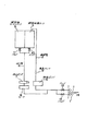
この種の加温設備として、従来、図8の設備、すなわち、燃料油貯蔵タンク1と、これと移送管2を介して連通された図示しない加熱装置を備えた燃料油澄タンク3と、燃料油貯蔵タンク1中の燃料油を燃料油澄タンク3に移送するための移送ポンプ4と、燃料油澄タンク3に連通された燃料油サービスタンク5と、燃料油澄タンク3および燃料油サービスタンク5のいずれか一方、または両方を燃料油貯蔵タンク1に連通する吸入管6と、吸入管6に設けられ、燃料油澄タンク3および燃料油サービスタンク5のいずれか一方、または両方の加熱された燃料油を燃料油貯蔵タンク1に流下せしめる流下ポンプ7とを備えた装置が知られている。図8において、8はヒータ、9は温度センサ、10、11、12、13はそれぞれバルブである。 Conventionally, as this type of heating equipment, the equipment shown in FIG. 8, that is, a fuel oil storage tank 1, a fuel oil tank 3 equipped with a heating device (not shown) communicated with the fuel oil storage tank 1, and a fuel, A transfer pump 4 for transferring the fuel oil in the oil storage tank 1 to the fuel oil tank 3, a fuel oil service tank 5 communicated with the fuel oil tank 3, the fuel oil tank 3 and the fuel oil service tank 5, a suction pipe 6 communicating with one or both of the fuel oil storage tank 1 and a suction pipe 6, and either one or both of the fuel oil tank 3 and the fuel oil service tank 5 are heated. There is known an apparatus including a flow-down pump 7 that causes the fuel oil to flow down to the fuel oil storage tank 1. In FIG. 8, 8 is a heater, 9 is a temperature sensor, 10, 11, 12, and 13 are valves.
上述の図8装置では、燃料油澄タンク3中の燃料油は図示しない加熱装置により加熱され、次いで図示しない燃料油清浄機で清浄されて燃料油サービスタンク5に送り込まれ、ここから図示しない主機、補機、ボイラ等に分配供給される。同時に、この加熱された燃料油の一部は流下ポンプ7の作動により燃料油貯蔵タンク1に該タンク1中の吸入主管14を通して流下され、該タンク1中の燃料油を加温する。
In the apparatus shown in FIG. 8, the fuel oil in the fuel oil tank 3 is heated by a heating device (not shown), then cleaned by a fuel oil cleaner (not shown) and sent to the fuel oil service tank 5, from which the main machine (not shown) , Distributed and supplied to auxiliaries, boilers, etc. At the same time, part of the heated fuel oil is caused to flow down to the fuel oil storage tank 1 through the suction
上述の図8装置において、加熱された燃料油の一部を燃料油澄タンク3ないしは燃料油サービスタンク5から燃料油貯蔵タンク1にもどして該タンク1中の燃料油を加温するとき、このもどす量および温度は吸入管6や移送管2の長さ、あるいは海水や、外気の温度変化、さらには燃料油貯蔵タンク1の大きさに対応して変化させる必要がある。 In the apparatus shown in FIG. 8, when a part of the heated fuel oil is returned from the fuel oil tank 3 or the fuel oil service tank 5 to the fuel oil storage tank 1, the fuel oil in the tank 1 is heated. The amount and temperature to be returned need to be changed in accordance with the length of the suction pipe 6 and the transfer pipe 2, the temperature change of seawater and outside air, and the size of the fuel oil storage tank 1.
すなわち、もどされる加熱された燃料油の熱量が適性値より多い場合には、海水や外気への熱量の放熱が多くなり、少ない場合には、所要量の燃料油の移送ができなくなり、このため、もどされる加熱された燃料油の量と温度を適性に保つ必要がある。 That is, when the amount of heat of the heated fuel oil to be returned is greater than the appropriate value, the amount of heat released to the seawater and the outside air increases, and when it is less, the required amount of fuel oil cannot be transferred, It is necessary to keep the amount and temperature of the heated fuel oil to be returned adequate.
しかし、上述の図8装置では、燃料油貯蔵タンク1に吸入主管14を通してもどされた加熱燃料油は温度が高くて比重が軽いため、すぐにタンク1内の上方に上昇してしまい、あるいは貯蔵タンク1全体に拡散し、放熱されてしまう。このため、吸入主管14の周辺は高粘度な冷温油のままであり、吸入主管14からの吸入が不良となり、熱効率がよくない。
However, in the above-described FIG. 8 apparatus, the heated fuel oil returned to the fuel oil storage tank 1 through the suction
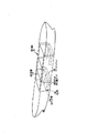
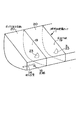
特に、図1および図2に示されるように、船底15に水のバラストタンク16を設け、その上に燃料油貯蔵タンク1を設け、さらにその上に荷物層17を設けて構成される三重底タイプの船舶Aでは図1に示されるように、燃料油貯蔵タンク1内に区切りがなく、広くなっており、このため、加熱された燃料油はタンク1全体にすぐに拡散され、燃料油貯蔵タンク1中の燃料油の加温が難しい。
In particular, as shown in FIGS. 1 and 2, a triple bottom constructed by providing a
この問題を解決する手段として、従来、貯蔵タンク1内の吸入主管14前につい立てを建立して加熱された燃料油の拡散を防ごうとする装置が知られている〔特願2001−115293(特開2002−308399)参照〕。
As a means for solving this problem, there is conventionally known a device that is designed to prevent the diffusion of heated fuel oil by setting up a stand in front of the suction
しかし、この装置の場合、高いないしは深い燃料タンクでは効果が大きいが、低い平らなタンクでは施工コストがかかる。
そこで、本発明の課題は加熱された燃料油を澄タンクやサービスタンクから貯蔵タンクに流下混合して該タンク中の燃料油を所望の温度に加温するに際し、タンク中の燃料油加温効率を部分的に向上させ、上述の公知技術に存する欠点を改良した燃料油貯蔵タンクを提供することにある。 Accordingly, an object of the present invention is to mix the heated fuel oil from the clarification tank or the service tank to the storage tank and warm the fuel oil in the tank to a desired temperature. It is an object of the present invention to provide a fuel oil storage tank that partially improves the above-mentioned problems and improves the above-mentioned drawbacks of the known art.
上述の課題を解決するため、本発明の燃料油貯蔵タンク中の燃料油の加熱方法によれば、加熱された燃料油を燃料油貯蔵タンク中の燃料油に、該タンク内に開孔された吸入主管を通して流下混合し、前記燃料油貯蔵タンク中の燃料油を加温する加熱方法において、前記吸入主管の先端周辺を区切り板で囲って前記貯蔵タンク内にボックス状小区画を形成し、このボックス状小区画に吸入主管の先端を通じて加熱燃料油を流入して該加熱燃料油の拡散、放熱を防止し、燃料油の加温効率を部分的に向上させることを特徴とする。 In order to solve the above-described problem, according to the heating method of the fuel oil in the fuel oil storage tank of the present invention, the heated fuel oil is opened in the fuel oil in the fuel oil storage tank. In the heating method in which the fuel oil in the fuel oil storage tank is heated and mixed through the suction main pipe and the fuel oil in the fuel oil storage tank is heated, a box-shaped small section is formed in the storage tank by surrounding the front end of the suction main pipe with a partition plate. Heated fuel oil flows into the box-shaped small section through the tip of the suction main pipe to prevent the heated fuel oil from diffusing and dissipating heat, thereby partially improving the heating efficiency of the fuel oil.
上述の本発明は吸入主管の先端周辺を区切り板で囲って先端をボックス状の小区画内に位置するようにしたから、先端を通して燃料油中に流入された加熱燃料油は拡散放熱が防止され、ボックス状小区画内の燃料油は効率よく加熱され、粘度が低くなって移送しやすくなる。 In the above-described present invention, the periphery of the tip of the suction main pipe is surrounded by the partition plate so that the tip is positioned in the box-shaped small section, so that the heated fuel oil flowing into the fuel oil through the tip is prevented from diffusing and radiating heat. The fuel oil in the box-shaped small section is efficiently heated, and the viscosity becomes low, so that it can be easily transported.
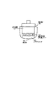
以下、本発明を添付図面を用いて詳述する。図1は船舶の燃料油貯蔵タンク内を示した斜視図である。図2は図1の横断面図である。図3は本発明にかかる燃料油貯蔵タンクの一具体例の斜視図である。図4、図5、図6および図7はそれぞれ発明にかかる燃料油貯蔵タンクの他の具体例の斜視図である。図8は燃料油貯蔵タンク中の燃料油の加熱システムを表したフローシートである。 Hereinafter, the present invention will be described in detail with reference to the accompanying drawings. FIG. 1 is a perspective view showing the inside of a marine fuel oil storage tank. FIG. 2 is a cross-sectional view of FIG. FIG. 3 is a perspective view of a specific example of the fuel oil storage tank according to the present invention. 4, FIG. 5, FIG. 6 and FIG. 7 are perspective views of other specific examples of the fuel oil storage tank according to the invention. FIG. 8 is a flow sheet showing a heating system for the fuel oil in the fuel oil storage tank.
図8に示されるように、燃料油貯蔵タンク1中の燃料油は燃料油澄タンク3で加熱された燃料油をタンク1中に設置された吸入主管14を通して燃料湯貯蔵タンク1中の燃料油に流下混合して加温される。
As shown in FIG. 8, the fuel oil in the fuel oil storage tank 1 is the fuel oil heated in the fuel oil tank 3 through the suction
この種の加温設備は図8において、燃料油貯蔵タンク1と、これと移送管2を介して連通された図示しない加熱装置を備えた燃料油澄タンク3と、燃料油貯蔵タンク1中の燃料油を燃料油澄タンク3に移送するための移送ポンプ4と、燃料油澄タンク3に連通された燃料油サービスタンク5と、燃料油澄タンク3および燃料油サービスタンク5のいずれか一方、または両方を燃料油貯蔵タンク1に連通する吸入管6と、吸入管6に設けられ、燃料油澄タンク3および燃料油サービスタンク5のいずれか一方、または両方の加熱された燃料油を燃料油貯蔵タンク1に流下せしめる流下ポンプ7とを備えて構成される。図8において、8はヒータ、9は温度センサ、10、11、12、13はそれぞれバルブである。 In FIG. 8, this type of heating equipment includes a fuel oil storage tank 1, a fuel oil tank 3 having a heating device (not shown) communicated with the fuel oil storage tank 1, and a fuel oil storage tank 1. A transfer pump 4 for transferring fuel oil to the fuel oil tank 3, a fuel oil service tank 5 communicated with the fuel oil tank 3, and one of the fuel oil tank 3 and the fuel oil service tank 5, Alternatively, a suction pipe 6 that communicates both with the fuel oil storage tank 1, and one of the fuel oil tank 3 and the fuel oil service tank 5, or both heated fuel oils are provided in the fuel pipe. A flow-down pump 7 that flows down to the storage tank 1 is provided. In FIG. 8, 8 is a heater, 9 is a temperature sensor, 10, 11, 12, and 13 are valves.
上述図8において、燃料油澄タンク3中の燃料油は図示しない加熱装置により加熱され、次いで図示しない燃料油清浄機で清浄されて燃料油サービスタンク5に送り込まれ、ここから図示しない主機、補機、ボイラ等に分配供給される。同時にこの加熱された燃料油の一部は流下ポンプ7の作動により燃料油貯蔵タンク1に該タンク1中の吸入主管14を通して流下され、該タンク1中の燃料油を加温する。
In FIG. 8 described above, the fuel oil in the fuel oil tank 3 is heated by a heating device (not shown), then cleaned by a fuel oil cleaner (not shown), and sent to the fuel oil service tank 5, from which the main engine and auxiliary equipment (not shown) Distributed to machine and boiler. At the same time, part of the heated fuel oil is caused to flow down to the fuel oil storage tank 1 through the suction
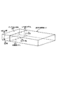
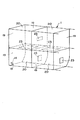
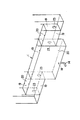
本発明の特徴は図3に示されるように、タンク1内に設置された吸入主管14の先端18周辺を1枚の区切り板19で燃料油貯蔵タンク1を横切る方向に配置して囲み、燃料油貯蔵タンク1内にボックス状小区画20を形成したことに存する。これにより、先端18はボックス状小区画20内に配置される。図3中、区切り板19の上側には、エア抜き用孔21が好ましくは複数個穿設され、下側には油通過用孔22が好ましくは複数個穿設される。なお、孔23は比較的大きな孔であって、油通過用ないしは人通行用の孔である。
The feature of the present invention is that, as shown in FIG. 3, the periphery of the
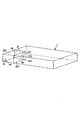
図4は本発明にかかる他の例の燃料油貯蔵タンク1であって、二枚の区切り板19、19で先端18を囲み、比較的小さなボックス状小区画20を形成した例である。
FIG. 4 shows another example of the fuel oil storage tank 1 according to the present invention, in which a
図5は本発明にかかるさらに他の例の燃料油貯蔵タンク1であって、複数板の区切り板19、19・・・19を、燃料油貯蔵タンク1を横切る方向に間隔をあけて配置して複数のボックス状小区画20、20・・・20を互いに隣接して形成し、いずれか一方のボックス状小区画20内の、例えば、左側のボックス状小区画20内に吸入主管14の先端18が位置するとともに、各ボックス状小区画20、20・・・20が区切り板19に設けられた孔23、23・・・23を通して互いに連通される。
FIG. 5 shows still another example of the fuel oil storage tank 1 according to the present invention, in which a plurality of
図6は本発明にかかるさらに他の例の燃料油貯蔵タンク1であって、複数の区切り板19、19・・・19を、燃料油貯蔵タンク1内で縦方向および横方向に間隔をあけて配置して複数のボックス状小区画20、20・・・20を縦方向および横方向に互いに隣接して形成し、かつ、いずれか一方のボックス状小区画20内に、例えば、左下のボックス状小区画20内に吸入主管14の先端18が位置するとともに、各ボックス状小区画20、20・・・20が区切り板19に設けられた孔23を通して互いに連通される。
FIG. 6 shows still another example of the fuel oil storage tank 1 according to the present invention, in which a plurality of
図7は本発明にかかるさらに他の例の燃料油貯蔵タンク1であって、複数の区切り板19、19・・・19を燃料油貯蔵タンク1内で縦方向および横方向に間隔をあけて配置して複数のボックス状小区画20、20・・・20を縦方向および横方向に互いに隣接してT字形状に形成する。そして、いずれか一方のボックス状小区画20内に、例えば、中央のボックス状小区画20の下方外側に吸入主管14が位置し、先端18のみがボックス状小区画20の内側に開孔する。さらに、各ボックス状小区画20、20・・・20は区切り板19に設けられた孔23を通して互いに連通される。
FIG. 7 shows still another example of the fuel oil storage tank 1 according to the present invention, in which a plurality of
すなわち、吸入主管14は図3、図4、図5および図6に示されるように、先端がベルマウスで形成され、全体が燃料油貯蔵タンク1内に配置されてもよい。また、吸入主管14は図7に示されるように、吸入主管14の本体が燃料油貯蔵タンク1の外側に配置され、先端18のみが燃料油貯蔵タンク1内に開孔されてもよい。
That is, as shown in FIGS. 3, 4, 5, and 6, the suction
上述図3、図4、図5、図6および図7にかかる本発明燃料油貯蔵タンク1は吸入主管14の先端18が燃油貯蔵タンク1内に形成されたボックス状小区画20に位置するため、先端18を通じて燃料油澄タンク3ないしは燃料油サービスタンク5から流入された加熱燃料油はボックス状小区画20によって拡散、放熱が防止され、燃料油の加温効率がボックス状小区画20内で部分的に向上する。
The fuel oil storage tank 1 according to the present invention shown in FIGS. 3, 4, 5, 6, and 7 is because the
燃料油貯蔵タンク1中にボックス状小区画20を設け、この中に吸入主管14の先端18を配置することによって、ボックス状小区画20内の燃料油が効率良く加温され、燃料油が低粘性になり、このため移送管2を通して燃料油澄タンク3への移送が容易となり、船舶への利用が期待される。
By providing the box-shaped
A 船舶
1 燃料油貯蔵タンク
14 吸入主管
15 船底
18 先端
19 区切り板
20 ボックス状小区画
23 孔
A Vessel 1 Fuel
Claims (7)
2. The method of heating fuel oil in a fuel oil storage tank according to claim 1, wherein the suction main pipe is disposed outside the fuel oil storage tank, and only the tip is opened in the tank.
Priority Applications (5)
| Application Number | Priority Date | Filing Date | Title |
|---|---|---|---|
| JP2005065312A JP4846251B2 (en) | 2004-03-17 | 2005-03-09 | Method for heating fuel oil in a fuel oil storage tank |
| TW094108078A TW200537019A (en) | 2004-03-17 | 2005-03-16 | Heating method for fuel oil in fuel oil storage tank |
| CN2005100548303A CN1669873B (en) | 2004-03-17 | 2005-03-17 | Heating method of fuel oil in fuel oil storage tank |
| KR1020050022249A KR20060043763A (en) | 2004-03-17 | 2005-03-17 | Method of heating fuel oil in fuel oil storage tank |
| HK06100472.1A HK1080438B (en) | 2004-03-17 | 2006-01-12 | A method for heating fuel oil in the fuel oil storage tank |
Applications Claiming Priority (3)
| Application Number | Priority Date | Filing Date | Title |
|---|---|---|---|
| JP2004075988 | 2004-03-17 | ||
| JP2004075988 | 2004-03-17 | ||
| JP2005065312A JP4846251B2 (en) | 2004-03-17 | 2005-03-09 | Method for heating fuel oil in a fuel oil storage tank |
Publications (2)
| Publication Number | Publication Date |
|---|---|
| JP2005297951A true JP2005297951A (en) | 2005-10-27 |
| JP4846251B2 JP4846251B2 (en) | 2011-12-28 |
Family
ID=35041361
Family Applications (1)
| Application Number | Title | Priority Date | Filing Date |
|---|---|---|---|
| JP2005065312A Expired - Fee Related JP4846251B2 (en) | 2004-03-17 | 2005-03-09 | Method for heating fuel oil in a fuel oil storage tank |
Country Status (4)
| Country | Link |
|---|---|
| JP (1) | JP4846251B2 (en) |
| KR (1) | KR20060043763A (en) |
| CN (1) | CN1669873B (en) |
| TW (1) | TW200537019A (en) |
Cited By (7)
| Publication number | Priority date | Publication date | Assignee | Title |
|---|---|---|---|---|
| JP2013053525A (en) * | 2011-08-31 | 2013-03-21 | Mitsubishi Heavy Ind Ltd | Fuel mixing tank and gas turbine power generation system including the same |
| CN106741654A (en) * | 2016-11-25 | 2017-05-31 | 上海佳豪船海工程研究设计有限公司 | Marine fuel oil pre-heating system and method |
| JP2018095310A (en) * | 2016-12-16 | 2018-06-21 | ホクシン産業株式会社 | Fuel oil transfer device |
| JP2018095311A (en) * | 2016-12-16 | 2018-06-21 | ホクシン産業株式会社 | Fuel oil transfer device |
| CN108372904A (en) * | 2017-01-31 | 2018-08-07 | 北辰产业株式会社 | Fuel oil transfer device |
| JP2018178962A (en) * | 2017-04-20 | 2018-11-15 | ホクシン産業株式会社 | Fuel oil transfer device |
| JP2019119252A (en) * | 2017-12-28 | 2019-07-22 | ホクシン産業株式会社 | Fuel transfer device |
Families Citing this family (10)
| Publication number | Priority date | Publication date | Assignee | Title |
|---|---|---|---|---|
| KR100862376B1 (en) * | 2007-10-16 | 2008-10-13 | 김현수 | Bunker Seed Oil Preheating Thermostat for Boiler |
| CN101362509B (en) * | 2008-09-04 | 2012-04-25 | 广州文冲船厂有限责任公司 | Installation method of steam heating coil for ship oil tanks |
| JP5530276B2 (en) * | 2010-07-08 | 2014-06-25 | ホクシン産業株式会社 | Fuel oil transfer device |
| JP6143407B2 (en) * | 2010-12-07 | 2017-06-07 | 三菱重工業株式会社 | Ship |
| JP6093681B2 (en) * | 2013-10-10 | 2017-03-08 | ホクシン産業株式会社 | Asphalt transfer method |
| CN104819080B (en) * | 2015-05-15 | 2017-03-01 | 上海船舶研究设计院 | A kind of marine fuel oil pre-heating mean |
| CN105089872B (en) * | 2015-08-27 | 2017-06-16 | 上海船舶研究设计院 | The marine fuel oil pre-heating system and its pre-heating mean of forced-convection heat transfer |
| CN105201699B (en) * | 2015-09-25 | 2017-07-18 | 上海船舶研究设计院 | Marine fuel oil pre-heating system and its pre-heating mean based on barrel forms |
| CN105626324B (en) * | 2016-03-22 | 2018-03-02 | 上海船舶研究设计院 | The control method and system that marine fuel oil pre-heating system high temperature fuel oil obtains |
| JP6440329B2 (en) * | 2016-12-16 | 2018-12-19 | ホクシン産業株式会社 | Fuel oil transfer device |
Citations (8)
| Publication number | Priority date | Publication date | Assignee | Title |
|---|---|---|---|---|
| JPS5772398A (en) * | 1980-10-23 | 1982-05-06 | Rion Co | Method of fabricating multilayer printed circuit board |
| JPS58110593A (en) * | 1981-07-16 | 1983-07-01 | 金 榮「そる」 | Novel manufacture of 7alpha-methoxy-7 beta- (cyanomethylthio)acetamido-3-(1-methyl-1h-tetrazol- 5-yl)-thiomethyl-3-cepham-4-carboxylic acid |
| JPH0326994U (en) * | 1989-07-27 | 1991-03-19 | ||
| JPH06298184A (en) * | 1993-03-22 | 1994-10-25 | Nippon High Hiiito Eng Kk | Heating of fuel oil tank of ship and respective local heating by dividing tank into large and small |
| JP2002308399A (en) * | 2001-04-13 | 2002-10-23 | Hokushin Sangyo Kk | Heat efficient fuel oil storage tank |
| JP2003231586A (en) * | 2002-02-06 | 2003-08-19 | Ishikawajima Harima Heavy Ind Co Ltd | Storage tanks and ships with the storage tanks |
| JP2004036594A (en) * | 2002-07-08 | 2004-02-05 | Hokushin Sangyo Kk | Method for heating fuel oil |
| JP2005219559A (en) * | 2004-02-04 | 2005-08-18 | Ihi Marine United Inc | Cargo boat |
Family Cites Families (4)
| Publication number | Priority date | Publication date | Assignee | Title |
|---|---|---|---|---|
| JPS56143996U (en) | 1980-03-31 | 1981-10-30 | ||
| CN2036249U (en) * | 1988-04-07 | 1989-04-19 | 王立功 | Oil tank of self-preheating evaporating oil-stove |
| JP3600269B2 (en) | 1994-05-24 | 2004-12-15 | 天信 千々波 | Fuel oil transfer device |
| US6076480A (en) * | 1999-02-11 | 2000-06-20 | The United States Of America As Represented By The Secretary Of The Navy | Fuel storing water ballast tank internally structured for reducing retention of water and overboard discharge of fuel |
-
2005
- 2005-03-09 JP JP2005065312A patent/JP4846251B2/en not_active Expired - Fee Related
- 2005-03-16 TW TW094108078A patent/TW200537019A/en not_active IP Right Cessation
- 2005-03-17 KR KR1020050022249A patent/KR20060043763A/en not_active Ceased
- 2005-03-17 CN CN2005100548303A patent/CN1669873B/en not_active Expired - Lifetime
Patent Citations (8)
| Publication number | Priority date | Publication date | Assignee | Title |
|---|---|---|---|---|
| JPS5772398A (en) * | 1980-10-23 | 1982-05-06 | Rion Co | Method of fabricating multilayer printed circuit board |
| JPS58110593A (en) * | 1981-07-16 | 1983-07-01 | 金 榮「そる」 | Novel manufacture of 7alpha-methoxy-7 beta- (cyanomethylthio)acetamido-3-(1-methyl-1h-tetrazol- 5-yl)-thiomethyl-3-cepham-4-carboxylic acid |
| JPH0326994U (en) * | 1989-07-27 | 1991-03-19 | ||
| JPH06298184A (en) * | 1993-03-22 | 1994-10-25 | Nippon High Hiiito Eng Kk | Heating of fuel oil tank of ship and respective local heating by dividing tank into large and small |
| JP2002308399A (en) * | 2001-04-13 | 2002-10-23 | Hokushin Sangyo Kk | Heat efficient fuel oil storage tank |
| JP2003231586A (en) * | 2002-02-06 | 2003-08-19 | Ishikawajima Harima Heavy Ind Co Ltd | Storage tanks and ships with the storage tanks |
| JP2004036594A (en) * | 2002-07-08 | 2004-02-05 | Hokushin Sangyo Kk | Method for heating fuel oil |
| JP2005219559A (en) * | 2004-02-04 | 2005-08-18 | Ihi Marine United Inc | Cargo boat |
Cited By (10)
| Publication number | Priority date | Publication date | Assignee | Title |
|---|---|---|---|---|
| JP2013053525A (en) * | 2011-08-31 | 2013-03-21 | Mitsubishi Heavy Ind Ltd | Fuel mixing tank and gas turbine power generation system including the same |
| CN106741654A (en) * | 2016-11-25 | 2017-05-31 | 上海佳豪船海工程研究设计有限公司 | Marine fuel oil pre-heating system and method |
| JP2018095310A (en) * | 2016-12-16 | 2018-06-21 | ホクシン産業株式会社 | Fuel oil transfer device |
| JP2018095311A (en) * | 2016-12-16 | 2018-06-21 | ホクシン産業株式会社 | Fuel oil transfer device |
| TWI639548B (en) * | 2016-12-16 | 2018-11-01 | 日商北新產業股份有限公司 | Fuel oil transfer device |
| CN108372904A (en) * | 2017-01-31 | 2018-08-07 | 北辰产业株式会社 | Fuel oil transfer device |
| JP2018122682A (en) * | 2017-01-31 | 2018-08-09 | ホクシン産業株式会社 | Fuel oil transfer device |
| JP2018178962A (en) * | 2017-04-20 | 2018-11-15 | ホクシン産業株式会社 | Fuel oil transfer device |
| JP2019119252A (en) * | 2017-12-28 | 2019-07-22 | ホクシン産業株式会社 | Fuel transfer device |
| JP7019172B2 (en) | 2017-12-28 | 2022-02-15 | ホクシン産業株式会社 | Fuel oil transfer device |
Also Published As
| Publication number | Publication date |
|---|---|
| HK1080438A1 (en) | 2006-04-28 |
| TW200537019A (en) | 2005-11-16 |
| CN1669873A (en) | 2005-09-21 |
| TWI301866B (en) | 2008-10-11 |
| JP4846251B2 (en) | 2011-12-28 |
| CN1669873B (en) | 2010-05-26 |
| KR20060043763A (en) | 2006-05-15 |
Similar Documents
| Publication | Publication Date | Title |
|---|---|---|
| JP4846251B2 (en) | Method for heating fuel oil in a fuel oil storage tank | |
| US20040079516A1 (en) | Keel cooler with fluid flow diverter | |
| EP2489973B1 (en) | Heat-storage device | |
| US20120111414A1 (en) | Method and apparatus for reservoir mixing | |
| JP2013133779A (en) | Blowby gas recirculation device | |
| JP3807596B2 (en) | Thermally efficient fuel oil storage tank | |
| JP2013245933A (en) | Water dispenser and thermoelectric heat pump apparatus used therefor | |
| CA2550845A1 (en) | Heat-storage unit and operation method of heat-storage unit | |
| CN107003077A (en) | cooler | |
| JP2008082692A (en) | Open-to-atmosphere heat storage device | |
| KR20110000572U (en) | Steam heater with three chambers | |
| JP6410325B2 (en) | Fuel oil transfer device | |
| JP4328350B2 (en) | Vertical flat heater | |
| KR101437809B1 (en) | A cooling tank using a thermoelectric module | |
| JP2007303803A (en) | Cargo heater | |
| JP2015155672A (en) | Engine cooling circuit | |
| JPH08313189A (en) | Heat exchanger with built-in tank | |
| AR003750A1 (en) | COMBUSTION ENGINE THERMOSTATIC VALVE | |
| KR100351307B1 (en) | Device for Separating Hot and Cold Waters for Supplier of Hot and Cold | |
| JPH08159684A (en) | Heat exchanger | |
| TWI253320B (en) | Water-cooling computer heat dissipation device | |
| JP2006224947A (en) | Bend heater for thermal diffusion type vessel oil tank | |
| JPS5849494Y2 (en) | Cold storage heat device | |
| JP2592234Y2 (en) | Heat exchanger | |
| JP6668169B2 (en) | Vaporizer |
Legal Events
| Date | Code | Title | Description |
|---|---|---|---|
| A621 | Written request for application examination |
Free format text: JAPANESE INTERMEDIATE CODE: A621 Effective date: 20080303 |
|
| A977 | Report on retrieval |
Free format text: JAPANESE INTERMEDIATE CODE: A971007 Effective date: 20100611 |
|
| A131 | Notification of reasons for refusal |
Free format text: JAPANESE INTERMEDIATE CODE: A131 Effective date: 20100622 |
|
| A521 | Request for written amendment filed |
Free format text: JAPANESE INTERMEDIATE CODE: A523 Effective date: 20100805 |
|
| A131 | Notification of reasons for refusal |
Free format text: JAPANESE INTERMEDIATE CODE: A131 Effective date: 20110208 |
|
| A521 | Request for written amendment filed |
Free format text: JAPANESE INTERMEDIATE CODE: A523 Effective date: 20110406 |
|
| TRDD | Decision of grant or rejection written | ||
| A01 | Written decision to grant a patent or to grant a registration (utility model) |
Free format text: JAPANESE INTERMEDIATE CODE: A01 Effective date: 20110913 |
|
| A01 | Written decision to grant a patent or to grant a registration (utility model) |
Free format text: JAPANESE INTERMEDIATE CODE: A01 |
|
| A61 | First payment of annual fees (during grant procedure) |
Free format text: JAPANESE INTERMEDIATE CODE: A61 Effective date: 20111012 |
|
| FPAY | Renewal fee payment (event date is renewal date of database) |
Free format text: PAYMENT UNTIL: 20141021 Year of fee payment: 3 |
|
| R150 | Certificate of patent or registration of utility model |
Ref document number: 4846251 Country of ref document: JP Free format text: JAPANESE INTERMEDIATE CODE: R150 Free format text: JAPANESE INTERMEDIATE CODE: R150 |
|
| R250 | Receipt of annual fees |
Free format text: JAPANESE INTERMEDIATE CODE: R250 |
|
| R250 | Receipt of annual fees |
Free format text: JAPANESE INTERMEDIATE CODE: R250 |
|
| R250 | Receipt of annual fees |
Free format text: JAPANESE INTERMEDIATE CODE: R250 |
|
| R250 | Receipt of annual fees |
Free format text: JAPANESE INTERMEDIATE CODE: R250 |
|
| R250 | Receipt of annual fees |
Free format text: JAPANESE INTERMEDIATE CODE: R250 |
|
| R250 | Receipt of annual fees |
Free format text: JAPANESE INTERMEDIATE CODE: R250 |
|
| R250 | Receipt of annual fees |
Free format text: JAPANESE INTERMEDIATE CODE: R250 |
|
| R250 | Receipt of annual fees |
Free format text: JAPANESE INTERMEDIATE CODE: R250 |
|
| LAPS | Cancellation because of no payment of annual fees |