JP2005297858A - Assembly of pneumatic tire and rim - Google Patents
Assembly of pneumatic tire and rim Download PDFInfo
- Publication number
- JP2005297858A JP2005297858A JP2004119311A JP2004119311A JP2005297858A JP 2005297858 A JP2005297858 A JP 2005297858A JP 2004119311 A JP2004119311 A JP 2004119311A JP 2004119311 A JP2004119311 A JP 2004119311A JP 2005297858 A JP2005297858 A JP 2005297858A
- Authority
- JP
- Japan
- Prior art keywords
- tire
- sound
- rim
- sheet
- synthetic resin
- Prior art date
- Legal status (The legal status is an assumption and is not a legal conclusion. Google has not performed a legal analysis and makes no representation as to the accuracy of the status listed.)
- Granted
Links
Images


Abstract
Description
本発明は、タイヤ内腔に、エアーキャップシート材からなる制音シートを配することにより、走行中のロードノイズを低減した空気入りタイヤとリムとの組立体に関する。 The present invention relates to an assembly of a pneumatic tire and a rim in which road noise during running is reduced by disposing a sound damping sheet made of an air cap sheet material in a tire lumen.
タイヤ騒音の一つに、路面を走行した際に、50〜400Hzの周波数範囲で「ゴー」という音が生じるいわゆるロードノイズがあり、その主原因として、タイヤ内腔内で起こす空気の共鳴振動(空洞共鳴)が知られている。 One of the tire noises is so-called road noise that produces a “go” sound in the frequency range of 50 to 400 Hz when traveling on the road surface, and the main cause is resonance vibration of air that occurs in the tire lumen ( Cavity resonance) is known.
そこで近年、タイヤ内腔内に、タイヤ周方向にのびる長尺帯状のスポンジ材からなる制音体を配し、タイヤ内腔内で生じた共鳴音エネルギーを緩和、吸収することにより、空洞共鳴を抑制しロードノイズを低減する技術が提案されている(例えば特許文献1、2参照)。 Therefore, in recent years, a sound damper made of a long strip-like sponge material extending in the tire circumferential direction is arranged in the tire lumen, and cavity resonance is reduced by relaxing and absorbing the resonance sound energy generated in the tire lumen. Techniques for suppressing road noise have been proposed (see, for example, Patent Documents 1 and 2).
しかし、スポンジ材は吸水性が高いため、タイヤ保管時やリム組時などにおいて雨水等に濡れて吸水してしまうという恐れが生じる。そして、この吸水状態でリム組みすると、吸水した水が重量バランスに悪影響を与え、タイヤ振動を発生させたり、又吸水した水がタイヤのゴム内に浸透して内部損傷を誘発させる等の問題を招く。そこで、リム組み時には、水を充分に取り除く必要があるが、いったん濡れたスポンジ材を瞬時に乾かすことは容易ではなく、その取り扱いを煩わしいものとしている。 However, since the sponge material has high water absorption, there is a risk that the sponge material may get wet by rainwater or the like when storing the tire or assembling the rim. If the rim is assembled in this water absorption state, the absorbed water will adversely affect the weight balance, causing tire vibration, and the absorbed water will penetrate into the tire rubber and cause internal damage. Invite. Therefore, when assembling the rim, it is necessary to remove water sufficiently, but it is not easy to instantly dry the sponge material once wet, and the handling is troublesome.
そこで本発明は、スポンジ材に代えて、合成樹脂フィルム間に複数の空気セルを設けたエアーキャップシート材を用いることを基本として、ロードノイズ低減効果を確保しながら、濡れた場合にも拭き取り等によって迅速に乾燥させることができ、取り扱い性を高め、かつ吸水に起因するタイヤ振動やタイヤ内部損傷等の諸問題を確実に防止しうる空気入りタイヤとリムとの組立体を提供することを目的としている。 Therefore, the present invention is based on using an air cap sheet material in which a plurality of air cells are provided between synthetic resin films instead of a sponge material, and wipes off even when wet while ensuring a road noise reduction effect. It is an object of the present invention to provide a pneumatic tire and rim assembly that can be quickly dried by the above-described method, can be easily handled, and can reliably prevent problems such as tire vibration and tire internal damage caused by water absorption. It is said.
前記目的を達成するために、本願請求項1の発明は、空気入りタイヤとこれをリム組みするリムとがなすタイヤ内腔に、制音シートを装着するとともに、
該制音シートは、合成樹脂フィルムの積層体からなりかつ少なくとも一方の合成樹脂フィルムに凸状に膨出する多数個の膨出部を形成することにより他方の合成樹脂フィルムとの間に空気セルを設けたエアーキャップシート材からなることを特徴としている。
In order to achieve the above object, the invention of claim 1 of the present application attaches a sound damping sheet to a tire lumen formed by a pneumatic tire and a rim for assembling the rim.
The sound damping sheet is composed of a laminate of synthetic resin films, and has an air cell between the other synthetic resin film by forming a plurality of bulging portions bulging convexly on at least one synthetic resin film. It is characterized by being made of an air cap sheet material provided with.
又請求項2の発明では、前記制音シートは、前記膨出部をタイヤ内腔に向けて、タイヤ側内腔面又はリム側内腔面に取り付けられることを特徴としている。 According to a second aspect of the present invention, the sound-damping sheet is attached to a tire-side lumen surface or a rim-side lumen surface with the bulging portion facing the tire lumen.
又請求項3の発明では、前記制音シートは、帯状をなし、かつその装着前の長さLaと巾Waとの積La×Waである制音シート面積Saを、前記タイヤの呼び巾Wtと外径Dtと円周率πとの積であるタイヤ呼び巾周面積Stの60〜115%としたことを特徴としている。
In the invention according to
又請求項4の発明では、前記制音シートは、その巾中心線をタイヤ赤道面に沿わせて、タイヤ内腔面に周方向に1以上の回数で巻回するとともに、その制音シートの巾方向の端縁とリムのフランジ最高高さ点との間の半径方向距離Kを3cm以上としたことを特徴としている。 According to a fourth aspect of the present invention, the sound-damping sheet has its width center line along the tire equator surface and is wound around the tire lumen surface in the circumferential direction one or more times. A radial distance K between the edge in the width direction and the flange maximum height point of the rim is 3 cm or more.
又請求項5の発明では、前記制音シートは、前記空気セルを円柱状とするとともに、その直径dを10〜50mm、かつ高さhを4〜30mmとしたことを特徴としている。 According to a fifth aspect of the present invention, the sound damping sheet is characterized in that the air cell has a cylindrical shape, a diameter d of 10 to 50 mm, and a height h of 4 to 30 mm.
本発明は叙上の如く構成しているため、ロードノイズの低減効果を確保しながら、濡れた場合にも拭き取り等によって迅速に乾燥させることができ、取り扱い性を高め、かつ吸水に起因するタイヤ振動やタイヤ内部損傷等の諸問題を確実に防止しうる。 Since the present invention is configured as described above, the tire can be quickly dried by wiping, etc. even when wet, while ensuring the effect of reducing road noise, improving the handleability, and resulting from water absorption Problems such as vibration and tire internal damage can be reliably prevented.
以下、本発明の実施の一形態を、図示例とともに説明する。
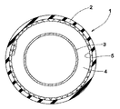
図1は本発明の空気入りタイヤとリムとの組立体(以下、単に「組立体」という場合がある)の子午断面図、図2は組立体のタイヤ赤道面に沿った周方向略断面図を示している。
Hereinafter, an embodiment of the present invention will be described with reference to the drawings.
FIG. 1 is a meridional sectional view of an assembly of a pneumatic tire and a rim according to the present invention (hereinafter sometimes simply referred to as “assembly”), and FIG. 2 is a schematic sectional view in the circumferential direction along the tire equatorial plane of the assembly. Is shown.
図1において、本実施形態の組立体1は、空気入りタイヤ2(単にタイヤ2という場合がある)と、これをリム組みするリム3とがなすタイヤ内腔4に、制音シート5を装着している。
In FIG. 1, an assembly 1 according to the present embodiment has a
前記リム3は、タイヤ2を嵌着する環状のリム本体3aと、このリム本体3aを支持しかつ車軸に固定するディスク3bとを具える周知構造をなし、本例では、正規リムを採用した場合を例示している。なお「正規リム」とは、タイヤが基づいている規格を含む規格体系において、各規格がタイヤ毎に定めているリムであり、JATMAであれば標準リム、TRAであれば "Design Rim" 、ETRTOであれば "Measuring Rim"を意味する。
The
また前記タイヤ2は、そのビード部2aを前記リム本体3aのフランジに密着させてリム組みされる例えば乗用車用ラジアルタイヤであって、タイヤ内腔4を囲む内腔面4Sのうちのタイヤ側内腔面4S1を、低空気透過性ゴムからなる所謂インナーライナゴムで形成したチューブレス構造を具える。これにより、タイヤ2は、前記リム本体3aとで気密なタイヤ内腔4を形成する。
The
そして前記タイヤ内腔4内には、エアーキャップシート材6からなる制音シート5を装着している。このエアーキャップシート材6は、図3(A)、(B)に示すように、例えば梱包・包装用材などとして知られる合成樹脂フィルム7の積層体であって、少なくとも一方の合成樹脂フィルム7aに、凸状に膨出する多数個の膨出部8を設けることにより、他方の合成樹脂フィルム7bとの間に、前記膨出部8をなす空気セル9を形成している。
A
このようなエアーキャップシート材6は、多数個の空気セル9を有するため、スポンジ材と同様クッション性に冨み、優れた防振・吸音性を発揮できる。しかも、エアーキャップシート材6は、少なくと一方の表面を、空気セル9の膨出部8が膨出する凹凸面Ssとしているため、音を乱反射させて攪乱するなど反射防止(攪乱)効果にも優れる。従って、前記防振・吸音性との相乗作用によって、タイヤ内腔4内で生じる共鳴音エネルギーを効果的に抑えることができ、ロードノイズを低減することが可能となる。
Since such an air
他方、エアーキャップシート材6は、その空気セル9が密封されているため、吸水性がない。従って、例えばタイヤ保管時やリム組時などにおいて雨水等に濡れてしまった場合にも、拭き取り等によって迅速かつ簡単に乾燥させることができ、その取り扱い性を高めうるとともに、吸水に起因するタイヤ振動やタイヤ内部損傷等の諸問題を確実に防止できる。
On the other hand, the air
なお、前記合成樹脂フィルム7としては、例えば、ポリエチレン、ポリ塩化ビニリデン、ポリプロピレン、ナイロン等の防水性を有する種々の熱可塑性樹脂フィルムが採用できる。又形成する空気セル9の形状も、例えば円柱状体、四角形,五角形等の多角形の角柱状体、半球状等の非柱状体、或いは不定型な形状であってもよいが、強度及び市場での入手の容易性等の観点から、本例の如き円柱状体のものが好適に採用しうる。
In addition, as the
ここで、前記エアーキャップシート材6からなる制音シート5では、その防振・吸音効果や反射防止(攪乱)効果を広範囲に亘って発揮させるために、タイヤ周方向にのびる長尺帯状に形成するのが好ましい。
Here, the
このとき制音シート5は、ロードノイズ低減効果の観点からは、前記内腔面4Sに取り付ける必要はないが、走行状態において前記制音シート5が内腔面4Sと擦れて損傷を受けるのを防止するために、或いはリム組み前の状態においてタイヤを移動させる際などに、制音シート5がタイヤから外れて汚損や損傷を受けるのを防止するために、前記制音シート5を内腔面4Sに取り付けることが好ましい。その際、制音シート5の巾中心線をタイヤ赤道面に沿わせた対称配置とするのが望ましい。
At this time, it is not necessary to attach the sound-
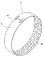
又前記取り付け手段としては、接着材を用い、前記制音シート5をタイヤ側内腔面4S1又はリム側内腔面4S2に貼着することができる。接着材としては、合成ゴムを主成分としてトルエン等の有機溶剤で溶解した溶液型、及び水に分散させたラテックス型などの合成ゴム系の液状接着剤が使用しうるが、接着作業性の観点から、アクリル系粘着材、シリコン系粘着材、及びポリエーテルやポリウレタン系粘着材を粘着層に用いた両面テープが好適できる。又他の取り付け手段としては、図4に概念的に示すように、該制音シート5を、タイヤ側内腔面4S1又はリム側内腔面4S2に沿って周回せしめ、その周方向端部5eを制音シート5本体に接着テープなどで連結した環状体とすることもできる。
Further, as the attachment means, an adhesive is used, and the sound-
何れの場合にも、前記凹凸面Ssによる音の反射防止(攪乱)効果を有効に発揮させるために、該凹凸面Ssをタイヤ内腔4の内方に向けて取り付けることが好ましい。
In any case, in order to effectively exhibit the sound reflection preventing (disturbing) effect by the uneven surface Ss, the uneven surface Ss is preferably attached toward the inside of the
又制音シート5では、リム側内腔面4S2に取り付ける場合には、制音シート5の周方向長さ及び巾を充分に確保することが難しく、しかもリム組時にビード部2aと擦れて空気セル9を潰して壊す危険性を有する。このことから、制音シート5を、タイヤ側内腔面4S1に取り付けるのが好ましく、特に、制音シート5を環状体としてタイヤ側内腔面4S1に接着材を用いることなく取り付ける場合には、制音シート5のタイヤ2からの取り外しも容易となるため、より好ましい態様となる。
In addition, when the
ここで、前記制音シート5の周方向長さ及び巾が少な過ぎると、その露出面積が過小となって、充分なロードノイズ低減効果が得られない。そのため、前記制音シート5は、図5の如く、その装着前の長さLaと巾Waとの積La×Waである制音シート面積Saを、前記タイヤ2の呼び巾Wtと外径Dtと円周率πとの積であるタイヤ呼び巾周面積Stの60〜115%の範囲とするのが好ましい。前記制音シート面積Saがタイヤ呼び巾周面積Stの60%未満では、ロードノイズ低減効果が不十分となり、逆に115%を越えると、制音シート5に生じる皺が大きくなって耐久性に不利となる。なお前記制音シート5が、環状体の場合には、前記長さLaは、一周分の周方向長さとする。
Here, if the circumferential length and width of the sound-
又前記空気セル9が小さすぎても、防振・吸音効果、及び音の反射防止(攪乱)効果を減じ、充分なロードノイズ低減効果が得られない。そのため、空気セル9は、円柱状態の場合には、その直径d(図3に示す)を10〜50mm、かつ高さhを4〜30mmとするのが好ましい。前記直径dが10mm未満、及び前記高さhが4mm未満では、ロードノイズ低減効果が不十分となる。従って、前記直径dは30mm以上、及び高さhは10mm以上が好ましい。なお制音シート5の側縁部では、空気セル9の一部が切断されて開口しているため防振・吸音効果を奏し得ず、前記直径dが50mmを越えると、その領域が増えるため、ロードノイズ低減効果が逆に減少するという不利を招く。又前記高さhが30mmを越えると、エアーキャップシート材6の製造工程上、前記合成樹脂フィルム7aの厚さが、前記膨出部8において薄くなり過ぎ、強度や耐久性を損ねるという不利を招く。なお前記空気セル9は、その容積Vを310〜58900mm3 とするのも好ましく、特に310〜7070mm2 とするのが好ましい。
Further, even if the
又前記制音シート5では、図6の如く、1以上の回数で巻回する、即ち複数回で周回させた複数層の環状体とするのが、ロードノイズ低減効果の観点から好ましい。しかしこのとき、制音シート5の巾方向の端縁Eとリム3のフランジ最高高さ点Pとの間の半径方向距離Kを3cm以上確保するのが好ましく、3cm未満では、リム組時にフランジと干渉して空気セル9を潰したり、環状体の積層を崩すなどのトラブルを招く恐れか生じる。なお制音シート5を複数層の環状体とする場合には、層間を前記液状接着剤や両面テープで接着し、層間の崩れを防止するのが好ましい。
In addition, as shown in FIG. 6, it is preferable that the
以上、本発明の特に好ましい実施形態について詳述したが、本発明は図示の実施形態に限定されることなく、種々の態様に変形して実施しうる。 As mentioned above, although especially preferable embodiment of this invention was explained in full detail, this invention is not limited to embodiment of illustration, It can deform | transform and implement in a various aspect.
制音シートを表1の仕様で試作するとともに、この制音シートを、タイヤ(195/65R15)のタイヤ側内腔面に、その巾中心線をタイヤ赤道面に沿わせて両面テープ(日東電工(株)製の型番5000NS)を用いて接着した。なおタイヤには、接着面部に加硫用
ブラダの排気用ベント溝跡のないもの、かつ剥離剤を軽減して加硫成形したものを使用している。そして制音シート付きタイヤにおける、気柱共鳴音低減効果、排水後の重量増加、排水後のタイヤ振動、リム組み性をテストし評価した。
A sound-proofing sheet was prototyped according to the specifications shown in Table 1, and this sound-proofing sheet was placed on the tire side lumen surface of the tire (195 / 65R15) and the width center line along the tire equatorial surface. Bonding was performed using a model No. 5000NS manufactured by Co., Ltd. In addition, tires that have no vulcanization bladder exhaust vent groove traces on the adhesive surface and those that are vulcanized and molded with reduced release agent are used. The tire with a noise control sheet was tested and evaluated for the effect of reducing air column resonance noise, weight increase after drainage, tire vibration after drainage, and rim assembly.
なお比較例1には、比重0.016のエーテル系ポリウレタンスポンジ((株)丸鈴製の型
番E16)を用い、実施例1〜12には、空気セルの直径dが10mm、高さhが4mmのエアーキャップシート(宇部フィルム(株)製のCタイプ)を使用し、実施例13、14に
は、空気セルの直径dが30mm、高さhが10mmのエアーキャップシート(宇部フィルム(株)製のDタイプ)を使用している。
In Comparative Example 1, an ether polyurethane sponge having a specific gravity of 0.016 (model number E16 manufactured by Maruzu) was used. In Examples 1 to 12, the diameter d of the air cell was 10 mm and the height h was A 4 mm air cap sheet (C type manufactured by Ube Film Co., Ltd.) was used. In Examples 13 and 14, an air cap sheet (Ube Film Co., Ltd.) having an air cell diameter d of 30 mm and a height h of 10 mm was used. ) D type).
(1)気柱共鳴音低減効果:
制音シート付きタイヤを、内圧(200kPa)で、車両(国産2000ccのFF車)の全輪に装着し、ロードノイズ計測路(アスファルト粗面路)を速度60km/hで走行したときの車内騒音を運転席窓側耳許位置にて測定し、240Hz付近の気柱共鳴音のピーク値の音圧レベルを、制音シートを装着してないタイヤを基準として比較した。数値が大きいほど気柱共鳴音低減効果に優れている。
(1) Air column resonance noise reduction effect:
In-vehicle noise when running on road noise measurement road (asphalt rough road) at a speed of 60 km / h with tires with sound control seats attached to all wheels of the vehicle (domestic 2000cc FF car) with internal pressure (200 kPa) Was measured at the driver's seat window side ear position, and the sound pressure level of the peak value of the air column resonance sound around 240 Hz was compared with a tire without a sound control seat as a reference. The larger the value, the better the air column resonance noise reduction effect.
(2)排水後の重量増加:
制音シート付きタイヤを縦置きした状態で、タイヤ内腔内に水を3リットル注ぎ、1時間経過後に水を捨てた状態での重量増加量を測定した。
(2) Weight increase after drainage:
In a state where the tire with a sound-damping sheet was placed vertically, 3 liters of water was poured into the tire lumen, and the amount of weight increase in a state where the water was discarded after 1 hour was measured.
(3)排水後のタイヤ振動:
前記水を捨てた状態の制音シート付きタイヤをリム組みし、内圧(200kPa)で、車両(国産2000ccのFF車)の全輪に装着し、周回路を速度100km/hで走行したときの振動の有無を、ドライバーの官能評価により検査した。
(3) Tire vibration after drainage:
When the tire with a sound-damping seat with the water discarded is assembled into a rim, mounted on all wheels of a vehicle (domestic 2000cc FF car) with internal pressure (200 kPa), and the peripheral circuit is run at a speed of 100 km / h The presence or absence of vibration was inspected by driver's sensory evaluation.
(4)リム組み性:
制音シート付きタイヤを、手組みによってリム(15×6.5JJ)に装着した際の制音シートへの干渉の有無を検査した。
(4) Rim assembly:
The presence or absence of interference with the sound control sheet when the tire with the sound control sheet was mounted on the rim (15 × 6.5JJ) by hand was inspected.

実施例のタイヤは、スポンジ材を使用したものと略同等のロードノイズ低減効果を確保しながら、濡れた場合にも吸水することがなく、この吸水に起因するタイヤ振動を確実に防止しうるのが確認できる。 The tires of the examples ensure a road noise reduction effect substantially equivalent to that using a sponge material, and even when wet, they do not absorb water and can reliably prevent tire vibration caused by this water absorption. Can be confirmed.
2 空気入りタイヤ
3 リム
4 タイヤ内腔
5 制音シート
6 エアーキャップシート材
7 合成樹脂フィルム
8 膨出部
9 空気セル
2
Claims (5)
該制音シートは、合成樹脂フィルムの積層体からなりかつ少なくとも一方の合成樹脂フィルムに凸状に膨出する多数個の膨出部を形成することにより他方の合成樹脂フィルムとの間に空気セルを設けたエアーキャップシート材からなることを特徴とする空気入りタイヤとリムとの組立体。 In addition to installing a sound control seat in the tire lumen formed by the pneumatic tire and the rim that assembles this,
The sound damping sheet is composed of a laminate of synthetic resin films, and has an air cell between the other synthetic resin film by forming a plurality of bulging portions bulging convexly on at least one synthetic resin film. An assembly of a pneumatic tire and a rim, characterized by comprising an air cap sheet material provided with an air cap.
Priority Applications (1)
| Application Number | Priority Date | Filing Date | Title |
|---|---|---|---|
| JP2004119311A JP4865993B2 (en) | 2004-04-14 | 2004-04-14 | Pneumatic tire and rim assembly |
Applications Claiming Priority (1)
| Application Number | Priority Date | Filing Date | Title |
|---|---|---|---|
| JP2004119311A JP4865993B2 (en) | 2004-04-14 | 2004-04-14 | Pneumatic tire and rim assembly |
Publications (2)
| Publication Number | Publication Date |
|---|---|
| JP2005297858A true JP2005297858A (en) | 2005-10-27 |
| JP4865993B2 JP4865993B2 (en) | 2012-02-01 |
Family
ID=35329916
Family Applications (1)
| Application Number | Title | Priority Date | Filing Date |
|---|---|---|---|
| JP2004119311A Expired - Fee Related JP4865993B2 (en) | 2004-04-14 | 2004-04-14 | Pneumatic tire and rim assembly |
Country Status (1)
| Country | Link |
|---|---|
| JP (1) | JP4865993B2 (en) |
Cited By (9)
| Publication number | Priority date | Publication date | Assignee | Title |
|---|---|---|---|---|
| JP2007112395A (en) * | 2005-10-24 | 2007-05-10 | Sumitomo Rubber Ind Ltd | Assembly of pneumatic tire and rim |
| JP2007276631A (en) * | 2006-04-06 | 2007-10-25 | Bridgestone Corp | Tire |
| JP2008273517A (en) * | 2007-04-26 | 2008-11-13 | Soc De Technol Michelin | Tire equipped with cellular layer |
| JP2012218470A (en) * | 2011-04-04 | 2012-11-12 | Toyo Tire & Rubber Co Ltd | Pneumatic tire |
| JP2014227069A (en) * | 2013-05-23 | 2014-12-08 | 横浜ゴム株式会社 | Tire/wheel assembly |
| WO2018235724A1 (en) * | 2017-06-19 | 2018-12-27 | 株式会社ブリヂストン | Pneumatic tire with noise-suppressing member, tire/rim assembly, and noise-suppressing member |
| US20190143753A1 (en) * | 2017-11-13 | 2019-05-16 | Gameel Gabriel | Balanced non-deflatable vehicle tire |
| CN110001311A (en) * | 2019-05-07 | 2019-07-12 | 江苏通用科技股份有限公司 | Low noise tire structure |
| CN115416433A (en) * | 2022-09-09 | 2022-12-02 | 东风汽车集团股份有限公司 | Centrifugal pendulum type perforated sound absorption tire and design method |
Citations (5)
| Publication number | Priority date | Publication date | Assignee | Title |
|---|---|---|---|---|
| JPH11217051A (en) * | 1998-02-03 | 1999-08-10 | Hayashi Gijutsu Kenkyusho:Kk | Interior material for automobile |
| JP2002052911A (en) * | 2000-08-09 | 2002-02-19 | Yokohama Rubber Co Ltd:The | Pneumatic tire |
| JP2003063208A (en) * | 2001-08-28 | 2003-03-05 | Sumitomo Rubber Ind Ltd | Assembly of pneumatic tire and rim |
| JP2003252003A (en) * | 2002-03-05 | 2003-09-09 | Sumitomo Rubber Ind Ltd | Assembly body of pneumatic tire and rim |
| JP2003316362A (en) * | 2002-04-19 | 2003-11-07 | Ngk Spark Plug Co Ltd | Soundproofing material and method of using this soundproofing material |
-
2004
- 2004-04-14 JP JP2004119311A patent/JP4865993B2/en not_active Expired - Fee Related
Patent Citations (5)
| Publication number | Priority date | Publication date | Assignee | Title |
|---|---|---|---|---|
| JPH11217051A (en) * | 1998-02-03 | 1999-08-10 | Hayashi Gijutsu Kenkyusho:Kk | Interior material for automobile |
| JP2002052911A (en) * | 2000-08-09 | 2002-02-19 | Yokohama Rubber Co Ltd:The | Pneumatic tire |
| JP2003063208A (en) * | 2001-08-28 | 2003-03-05 | Sumitomo Rubber Ind Ltd | Assembly of pneumatic tire and rim |
| JP2003252003A (en) * | 2002-03-05 | 2003-09-09 | Sumitomo Rubber Ind Ltd | Assembly body of pneumatic tire and rim |
| JP2003316362A (en) * | 2002-04-19 | 2003-11-07 | Ngk Spark Plug Co Ltd | Soundproofing material and method of using this soundproofing material |
Cited By (13)
| Publication number | Priority date | Publication date | Assignee | Title |
|---|---|---|---|---|
| JP2007112395A (en) * | 2005-10-24 | 2007-05-10 | Sumitomo Rubber Ind Ltd | Assembly of pneumatic tire and rim |
| JP2007276631A (en) * | 2006-04-06 | 2007-10-25 | Bridgestone Corp | Tire |
| JP2008273517A (en) * | 2007-04-26 | 2008-11-13 | Soc De Technol Michelin | Tire equipped with cellular layer |
| JP2012218470A (en) * | 2011-04-04 | 2012-11-12 | Toyo Tire & Rubber Co Ltd | Pneumatic tire |
| JP2014227069A (en) * | 2013-05-23 | 2014-12-08 | 横浜ゴム株式会社 | Tire/wheel assembly |
| JP2019001395A (en) * | 2017-06-19 | 2019-01-10 | 株式会社ブリヂストン | Pneumatic tire with noise damper component, tire-rim assembly, and noise damper component |
| WO2018235724A1 (en) * | 2017-06-19 | 2018-12-27 | 株式会社ブリヂストン | Pneumatic tire with noise-suppressing member, tire/rim assembly, and noise-suppressing member |
| CN110753626A (en) * | 2017-06-19 | 2020-02-04 | 株式会社普利司通 | Pneumatic tire with noise reduction member, tire rim assembly, and noise reduction member |
| JP2021185082A (en) * | 2017-06-19 | 2021-12-09 | 株式会社ブリヂストン | Pneumatic tire with noise damper member, tire-rim assembly, and noise damper component |
| US20190143753A1 (en) * | 2017-11-13 | 2019-05-16 | Gameel Gabriel | Balanced non-deflatable vehicle tire |
| CN110001311A (en) * | 2019-05-07 | 2019-07-12 | 江苏通用科技股份有限公司 | Low noise tire structure |
| CN115416433A (en) * | 2022-09-09 | 2022-12-02 | 东风汽车集团股份有限公司 | Centrifugal pendulum type perforated sound absorption tire and design method |
| CN115416433B (en) * | 2022-09-09 | 2024-01-19 | 东风汽车集团股份有限公司 | Centrifugal pendulum type perforated sound absorption tire and design method |
Also Published As
| Publication number | Publication date |
|---|---|
| JP4865993B2 (en) | 2012-02-01 |
Similar Documents
| Publication | Publication Date | Title |
|---|---|---|
| JP4318639B2 (en) | Pneumatic tire and rim assembly, and sound absorber used therefor | |
| JP3964878B2 (en) | Pneumatic tire and rim assembly | |
| JP3622957B2 (en) | Pneumatic tire and rim assembly | |
| JP4520936B2 (en) | Pneumatic tire with noise control | |
| JP3621899B2 (en) | Pneumatic tire and rim assembly | |
| JP3953264B2 (en) | Pneumatic tire and rim assembly | |
| JP4427007B2 (en) | Pneumatic tire | |
| CN100355593C (en) | Pneumatic tire with noise damper | |
| CN100554010C (en) | Air-inflation tyre with noise damper | |
| JP3787343B2 (en) | Pneumatic tire and rim assembly | |
| EP1876038B1 (en) | Assembly of pneumatic tire and rim | |
| JP4787784B2 (en) | Pneumatic tire set | |
| EP1745947B1 (en) | Pneumatic tire with noise absorbing insert | |
| RU2684991C2 (en) | Noiseless tire for vehicle wheels | |
| JP6519471B2 (en) | Pneumatic tire | |
| JP4971722B2 (en) | Pneumatic tire | |
| JP4865993B2 (en) | Pneumatic tire and rim assembly | |
| EP3722113B1 (en) | Pneumatic tire comprising resonance noise reduction structure | |
| JP4533130B2 (en) | Pneumatic tire and rim assembly | |
| JP2009051297A (en) | Manufacturing method of pneumatic tire, and pneumatic tire | |
| JP4728790B2 (en) | Pneumatic tire and rim assembly | |
| JP4575765B2 (en) | Pneumatic tire and rim assembly | |
| JP2002307905A (en) | Assembly of pneumatic tire and rim | |
| JP3990533B2 (en) | Pneumatic tire and rim assembly | |
| JP2009029098A (en) | Method for producing pneumatic tire and pneumatic tire |
Legal Events
| Date | Code | Title | Description |
|---|---|---|---|
| A621 | Written request for application examination |
Free format text: JAPANESE INTERMEDIATE CODE: A621 Effective date: 20070125 |
|
| A977 | Report on retrieval |
Free format text: JAPANESE INTERMEDIATE CODE: A971007 Effective date: 20091202 |
|
| A131 | Notification of reasons for refusal |
Free format text: JAPANESE INTERMEDIATE CODE: A131 Effective date: 20091208 |
|
| A521 | Written amendment |
Free format text: JAPANESE INTERMEDIATE CODE: A523 Effective date: 20100106 |
|
| A131 | Notification of reasons for refusal |
Free format text: JAPANESE INTERMEDIATE CODE: A131 Effective date: 20110208 |
|
| A521 | Written amendment |
Free format text: JAPANESE INTERMEDIATE CODE: A523 Effective date: 20110317 |
|
| TRDD | Decision of grant or rejection written | ||
| A01 | Written decision to grant a patent or to grant a registration (utility model) |
Free format text: JAPANESE INTERMEDIATE CODE: A01 Effective date: 20111108 |
|
| A01 | Written decision to grant a patent or to grant a registration (utility model) |
Free format text: JAPANESE INTERMEDIATE CODE: A01 |
|
| A61 | First payment of annual fees (during grant procedure) |
Free format text: JAPANESE INTERMEDIATE CODE: A61 Effective date: 20111111 |
|
| FPAY | Renewal fee payment (event date is renewal date of database) |
Free format text: PAYMENT UNTIL: 20141118 Year of fee payment: 3 |
|
| R150 | Certificate of patent or registration of utility model |
Free format text: JAPANESE INTERMEDIATE CODE: R150 |
|
| LAPS | Cancellation because of no payment of annual fees |