JP2005297851A - Wheel condition adjustment system - Google Patents
Wheel condition adjustment system Download PDFInfo
- Publication number
- JP2005297851A JP2005297851A JP2004119152A JP2004119152A JP2005297851A JP 2005297851 A JP2005297851 A JP 2005297851A JP 2004119152 A JP2004119152 A JP 2004119152A JP 2004119152 A JP2004119152 A JP 2004119152A JP 2005297851 A JP2005297851 A JP 2005297851A
- Authority
- JP
- Japan
- Prior art keywords
- wheel
- tire
- state
- transmission mode
- air pressure
- Prior art date
- Legal status (The legal status is an assumption and is not a legal conclusion. Google has not performed a legal analysis and makes no representation as to the accuracy of the status listed.)
- Pending
Links
Images

Classifications
-
- B—PERFORMING OPERATIONS; TRANSPORTING
- B60—VEHICLES IN GENERAL
- B60C—VEHICLE TYRES; TYRE INFLATION; TYRE CHANGING; CONNECTING VALVES TO INFLATABLE ELASTIC BODIES IN GENERAL; DEVICES OR ARRANGEMENTS RELATED TO TYRES
- B60C23/00—Devices for measuring, signalling, controlling, or distributing tyre pressure or temperature, specially adapted for mounting on vehicles; Arrangement of tyre inflating devices on vehicles, e.g. of pumps or of tanks; Tyre cooling arrangements
- B60C23/02—Signalling devices actuated by tyre pressure
- B60C23/04—Signalling devices actuated by tyre pressure mounted on the wheel or tyre
- B60C23/0408—Signalling devices actuated by tyre pressure mounted on the wheel or tyre transmitting the signals by non-mechanical means from the wheel or tyre to a vehicle body mounted receiver
-
- B—PERFORMING OPERATIONS; TRANSPORTING
- B60—VEHICLES IN GENERAL
- B60C—VEHICLE TYRES; TYRE INFLATION; TYRE CHANGING; CONNECTING VALVES TO INFLATABLE ELASTIC BODIES IN GENERAL; DEVICES OR ARRANGEMENTS RELATED TO TYRES
- B60C23/00—Devices for measuring, signalling, controlling, or distributing tyre pressure or temperature, specially adapted for mounting on vehicles; Arrangement of tyre inflating devices on vehicles, e.g. of pumps or of tanks; Tyre cooling arrangements
- B60C23/001—Devices for manually or automatically controlling or distributing tyre pressure whilst the vehicle is moving
- B60C23/003—Devices for manually or automatically controlling or distributing tyre pressure whilst the vehicle is moving comprising rotational joints between vehicle-mounted pressure sources and the tyres
- B60C23/00309—Devices for manually or automatically controlling or distributing tyre pressure whilst the vehicle is moving comprising rotational joints between vehicle-mounted pressure sources and the tyres characterised by the location of the components, e.g. valves, sealings, conduits or sensors
- B60C23/00318—Devices for manually or automatically controlling or distributing tyre pressure whilst the vehicle is moving comprising rotational joints between vehicle-mounted pressure sources and the tyres characterised by the location of the components, e.g. valves, sealings, conduits or sensors on the wheels or the hubs
-
- B—PERFORMING OPERATIONS; TRANSPORTING
- B60—VEHICLES IN GENERAL
- B60C—VEHICLE TYRES; TYRE INFLATION; TYRE CHANGING; CONNECTING VALVES TO INFLATABLE ELASTIC BODIES IN GENERAL; DEVICES OR ARRANGEMENTS RELATED TO TYRES
- B60C23/00—Devices for measuring, signalling, controlling, or distributing tyre pressure or temperature, specially adapted for mounting on vehicles; Arrangement of tyre inflating devices on vehicles, e.g. of pumps or of tanks; Tyre cooling arrangements
- B60C23/001—Devices for manually or automatically controlling or distributing tyre pressure whilst the vehicle is moving
- B60C23/003—Devices for manually or automatically controlling or distributing tyre pressure whilst the vehicle is moving comprising rotational joints between vehicle-mounted pressure sources and the tyres
- B60C23/00354—Details of valves
-
- B—PERFORMING OPERATIONS; TRANSPORTING
- B60—VEHICLES IN GENERAL
- B60C—VEHICLE TYRES; TYRE INFLATION; TYRE CHANGING; CONNECTING VALVES TO INFLATABLE ELASTIC BODIES IN GENERAL; DEVICES OR ARRANGEMENTS RELATED TO TYRES
- B60C23/00—Devices for measuring, signalling, controlling, or distributing tyre pressure or temperature, specially adapted for mounting on vehicles; Arrangement of tyre inflating devices on vehicles, e.g. of pumps or of tanks; Tyre cooling arrangements
- B60C23/001—Devices for manually or automatically controlling or distributing tyre pressure whilst the vehicle is moving
- B60C23/003—Devices for manually or automatically controlling or distributing tyre pressure whilst the vehicle is moving comprising rotational joints between vehicle-mounted pressure sources and the tyres
- B60C23/00372—Devices for manually or automatically controlling or distributing tyre pressure whilst the vehicle is moving comprising rotational joints between vehicle-mounted pressure sources and the tyres characterised by fluid diagrams
Landscapes
- Engineering & Computer Science (AREA)
- Mechanical Engineering (AREA)
- Measuring Fluid Pressure (AREA)
- Arrangements For Transmission Of Measured Signals (AREA)
- Tires In General (AREA)
Abstract
【課題】 タイヤの内部空気圧などの車輪の所定状態量を適切に監視して調整することができる技術を提供することにある。
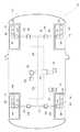
【解決手段】 車輪14には、タイヤの内部空気圧を検出する圧力検出センサ30と、圧力検出センサ30の検出結果を所定の送信モードによって送信する車輪側通信装置34とが設けられている。圧力検出センサ30の検出結果は、車体12に設けられた車体側通信装置16を介してECU26に送られる。ECU26は、タイヤの内部空気圧の状態を操作することにより、エアー調整電磁弁24等によってタイヤの内部空気圧の調整を実施することを、各車輪に設けられた送信モード決定装置32に伝えることができる。送信モード決定装置32は、タイヤの内部空気圧の調整が実施されている間は送信頻度を抑制するように、車輪側通信装置の送信モードを決定する。
【選択図】 図1
PROBLEM TO BE SOLVED: To provide a technique capable of appropriately monitoring and adjusting a predetermined state quantity of a wheel such as an internal air pressure of a tire.
A wheel 14 is provided with a pressure detection sensor 30 for detecting an internal air pressure of a tire, and a wheel side communication device 34 for transmitting a detection result of the pressure detection sensor 30 in a predetermined transmission mode. The detection result of the pressure detection sensor 30 is sent to the ECU 26 via the vehicle body side communication device 16 provided in the vehicle body 12. The ECU 26 can notify the transmission mode determination device 32 provided in each wheel that the internal air pressure of the tire is adjusted by the air adjustment electromagnetic valve 24 or the like by operating the internal air pressure state of the tire. . The transmission mode determination device 32 determines the transmission mode of the wheel side communication device so as to suppress the transmission frequency while the internal air pressure of the tire is being adjusted.
[Selection] Figure 1
Description
本発明は、車輪の所定状態量を調整する車輪状態調整システムに係り、例えばタイヤの内部空気圧を調整するものに関する。 The present invention relates to a wheel state adjustment system that adjusts a predetermined state amount of a wheel, for example, to an item that adjusts an internal air pressure of a tire.
タイヤの内部空気圧等の車輪状態を監視することは、適切な状態の車輪によって快適な車両走行を実現する上で好ましい。そのため、タイヤ内の圧力変化などの車輪状態を監視する様々な手法が従来から提案されてきている(例えば、特許文献1および特許文献2参照)。
車輪の所定状態量を監視して適切な状態に維持する従来のシステムは、タイヤの内部空気圧等の車輪状態を、車体に設けられたセンサ類、あるいは車体に設けられた機器類と一体的に設けられたセンサ類によって検出するものが多い。 A conventional system that monitors a predetermined amount of state of a wheel and maintains it in an appropriate state is such that the state of a wheel such as the internal air pressure of a tire is integrated with sensors provided on the vehicle body or devices provided on the vehicle body. Many are detected by provided sensors.
ところで、最近では、タイヤ空気圧モニタリングシステム(以下、「TPMS」と表記する)に代表されるように、タイヤの内部空気圧などの車輪状態を、各車輪に設けられたセンサ類により検出して、車体に設けられた電子制御装置(以下、「ECU」と表記する)などに送信するシステムが普及してきている。各車輪に設けられたセンサ類は、車輪状態に応じて作動モードを切り換えるものが多い。例えば、通常時には低頻度で車輪状態を検出するが、異常が生じているおそれがあると判断される時には高頻度で車輪状態を検出するセンサ類がTPMSなどのシステムに採用され、安全性の向上が図られている。 By the way, recently, as represented by a tire pressure monitoring system (hereinafter referred to as “TPMS”), a wheel state such as a tire internal pressure is detected by sensors provided on each wheel, A system for transmitting to an electronic control device (hereinafter referred to as “ECU”) or the like provided in the vehicle has become widespread. Many sensors provided on each wheel switch the operation mode in accordance with the wheel state. For example, while detecting the wheel state at a low frequency in normal times, sensors that detect the wheel state at a high frequency when it is determined that there is a possibility that an abnormality has occurred are adopted in a system such as TPMS to improve safety. Is planned.
また、車輪に設けられるセンサ類は、車体側に設けられたバッテリーではなく、車輪側に設けられた電池をエネルギー源としていることが多い。そのため、電池により長期間にわたってセンサ類を作動させるためには、センサ類を無駄なく作動させてエネルギー消費量を節約することが大切である。例えば、タイヤの内部空気圧が走行路に応じた適圧に積極的に調整されるような車両では、そのようなタイヤの内部空気圧の積極的な調整のために、車輪に異常が生じているおそれがない場合であっても、センサ類が誤作動してしまい車輪状態の検出動作や当該検出結果の送信動作を高頻度で行ってしまうことがある。センサ類を誤作動させて車輪状態の検出を必要以上に行うことは、エネルギー消費量を節約するという観点からは必ずしも好ましいとはいえない。 In many cases, sensors provided on the wheels use not the battery provided on the vehicle body side but the battery provided on the wheel side as an energy source. Therefore, in order to operate the sensors for a long period of time with a battery, it is important to operate the sensors without waste and to save energy consumption. For example, in a vehicle in which the internal air pressure of a tire is positively adjusted to an appropriate pressure according to the traveling road, there is a possibility that the wheels may be abnormal due to the active adjustment of the internal air pressure of the tire. Even if there is not, the sensors may malfunction and the wheel state detection operation and the detection result transmission operation may be frequently performed. It is not always preferable to erroneously operate the sensors to detect the wheel state more than necessary from the viewpoint of saving energy consumption.
本発明は上述の事情を鑑みてなされたものであり、その目的は、車輪の所定状態量を適切に監視して調整することができる技術を提供することにある。 This invention is made | formed in view of the above-mentioned situation, The objective is to provide the technique which can monitor and adjust the predetermined state quantity of a wheel appropriately.
本発明の一態様は車輪状態調整システムに関する。この車輪状態調整システムは、車輪の所定状態量を監視して当該車輪の異常発生を通知する車輪状態監視手段と、前記車輪の所定状態量の調整を実施する車輪状態調整手段と、を備え、前記車輪状態監視手段は、前記車輪状態調整手段が前記車輪の所定状態量の調整を実施している間は、前記車輪の異常発生の通知頻度を抑制する。 One aspect of the present invention relates to a wheel condition adjustment system. The wheel state adjustment system includes a wheel state monitoring unit that monitors a predetermined state amount of a wheel and notifies the occurrence of an abnormality of the wheel, and a wheel state adjustment unit that performs adjustment of the predetermined state amount of the wheel, The wheel state monitoring unit suppresses the notification frequency of occurrence of abnormality of the wheel while the wheel state adjusting unit adjusts the predetermined state amount of the wheel.
当該車輪状態調整システムによれば、車輪の所定状態量の監視および異常発生の通知と、車輪の所定状態量の調整とを実施可能である。そして、車輪状態調整手段が車輪の所定状態量の調整を実施している間は、車輪の異常発生の通知頻度を抑制して、車輪の異常発生の通知に伴うエネルギー消費量を節約することができる。なお、ここでいう「車輪の所定状態量」には、車輪の様々な状態に関するものが含まれ、例えばタイヤの内部空気圧などが含まれる。また「車輪の異常発生」というのは、車輪に異常が発生している可能性が高い場合を含む概念である。また、「車輪の異常発生の通知」というのは、車輪に異常が発生していることを直接通知する場合の他に、送信頻度等に特徴をもたせることによって車輪に異常が発生していることを間接的に通知する場合も含む。 According to the wheel state adjustment system, it is possible to monitor the predetermined state quantity of the wheel, notify the occurrence of an abnormality, and adjust the predetermined state quantity of the wheel. And while the wheel state adjustment means is adjusting the predetermined state quantity of the wheel, the frequency of notification of the occurrence of the wheel abnormality can be suppressed to save the energy consumption accompanying the notification of the occurrence of the wheel abnormality. it can. The “predetermined amount of state of the wheel” here includes items related to various states of the wheel, for example, the internal air pressure of the tire. Further, the “occurrence of wheel abnormality” is a concept including a case where there is a high possibility that an abnormality has occurred in the wheel. Also, “notification of occurrence of wheel abnormality” means that there is an abnormality in the wheel by giving a characteristic to the transmission frequency, etc. in addition to notifying directly that an abnormality has occurred in the wheel It also includes the case of indirect notification.
前記車輪状態監視手段は、前記車輪状態調整手段が前記車輪の所定状態量の調整を実施している間は、前記車輪の異常発生の通知を停止することによって前記車輪の異常発生の通知頻度を抑制するようにしてもよい。この場合には、車輪の異常発生の通知が停止されるので、車輪の異常発生の通知に伴うエネルギー消費量を減少させて節約することが可能である。 The wheel state monitoring means stops the notification of the occurrence of abnormality of the wheel by stopping the notification of the occurrence of abnormality of the wheel while the wheel state adjustment means is adjusting the predetermined state quantity of the wheel. You may make it suppress. In this case, since the notification of the occurrence of the wheel abnormality is stopped, the energy consumption accompanying the notification of the occurrence of the wheel abnormality can be reduced and saved.
前記車輪状態監視手段は、前記車輪状態調整手段が前記車輪の所定状態量の調整を実施している間は、前記車輪の異常発生の判断条件を変更することによって車輪の異常発生の通知頻度を抑制するようにしてもよい。一般に、車輪に異常が発生していないのに、車輪状態調整手段が車輪の所定状態量の調整することによって、車輪状態監視手段が車輪に異常が発生していると誤って判断されてしまうことがある。しかしながら、当該車輪状態調整システムによれば、車輪の異常発生の判断条件を適宜変更することにより、そのような誤った判断を効果的に防ぐことができる。 While the wheel state adjusting unit is adjusting the predetermined state quantity of the wheel, the wheel state monitoring unit changes the determination condition of the wheel abnormality occurrence to change the notification frequency of the wheel abnormality occurrence. You may make it suppress. In general, even though no abnormality has occurred in the wheel, the wheel state monitoring means erroneously determines that the wheel has an abnormality because the wheel state adjusting means adjusts the predetermined state amount of the wheel. There is. However, according to the wheel state adjustment system, such erroneous determination can be effectively prevented by appropriately changing the determination condition for the occurrence of a wheel abnormality.
前記車輪状態調整手段は、前記車輪の所定状態量を操作することによって、前記車輪状態調整手段による前記車輪の所定状態量の調整の実施の有無を車輪状態監視手段に伝えるようにしてもよい。この場合、「車輪状態調整手段による車輪の所定状態量の操作」という簡素な手法によって、車輪状態調整手段による車輪の所定状態量の調整の実施の有無を車輪状態監視手段に伝えることが可能である。 The wheel state adjusting unit may notify the wheel state monitoring unit of whether or not the wheel state adjusting unit has performed the adjustment of the predetermined state amount of the wheel by operating the predetermined state amount of the wheel. In this case, it is possible to inform the wheel state monitoring means of whether or not the wheel state adjusting means has performed the adjustment of the predetermined state quantity of the wheel by a simple method “operation of the predetermined state quantity of the wheel by the wheel state adjusting means”. is there.
前記車輪状態調整手段は、通常はとらない振る舞いを前記車輪の所定状態量が示すように操作することによって、前記車輪の所定状態量の調整を実施していることを前記車輪状態監視手段に伝えるようにしてもよい。当該車輪状態調整システムによれば、車輪の所定状態量の通常時の挙動と、前記車輪の所定状態量の調整に起因する車輪の所定状態量の挙動とを区別することができ、混同してしまうことを防ぐことが可能である。ここでいう「通常はとらない振る舞い」とは、例えば車輪が自然な状態におかれている場合にはとらない振る舞いを指し、車輪の損傷や環境に起因する車輪の所定状態量の振る舞いとは異なる振る舞いが含まれうる。 The wheel state adjusting means informs the wheel state monitoring means that the predetermined state quantity of the wheel is being adjusted by operating the wheel state adjusting means so that the predetermined state quantity of the wheel indicates a behavior that is not normally taken. You may do it. According to the wheel state adjustment system, the normal behavior of the predetermined state quantity of the wheel can be distinguished from the behavior of the predetermined state quantity of the wheel resulting from the adjustment of the predetermined state quantity of the wheel. Can be prevented. The “normal behavior” here refers to behavior that is not taken when the wheel is in a natural state, for example, and behavior of a predetermined state amount of the wheel caused by wheel damage or the environment. Different behaviors can be included.
前記車輪状態調整手段は、前記車輪状態監視手段による前記車輪の所定状態量の監視結果を参照して、前記車輪の所定状態量の調整を実施するようにしてもよい。この場合には、車輪の所定状態量の変化に応じて、当該所定状態量の調整を実施することが可能である。 The wheel state adjusting unit may adjust the predetermined state amount of the wheel with reference to a monitoring result of the predetermined state amount of the wheel by the wheel state monitoring unit. In this case, the predetermined state quantity can be adjusted according to a change in the predetermined state quantity of the wheel.
前記車輪状態調整手段は、前記車輪が取り付けられる車両の速度を参照して、前記車輪の所定状態量の調整を実施するようにしてもよい。この場合には、車両速度に応じて安全に車輪の所定状態量の調整を実施することが可能である。 The wheel state adjusting means may adjust a predetermined state amount of the wheel with reference to a speed of a vehicle to which the wheel is attached. In this case, it is possible to safely adjust the predetermined state amount of the wheel according to the vehicle speed.
前記車輪の所定状態量は、タイヤの内部空気圧であってもよい。路面と接触するタイヤは損傷や環境の影響を受けやすく、タイヤの内部空気圧を適正に保つことは大切である。当該車輪状態調整システムによれば、タイヤの内部空気圧を適切に監視して調整することが可能である。 The predetermined state quantity of the wheel may be an internal air pressure of the tire. Tires that come into contact with the road surface are easily affected by damage and the environment, and it is important to maintain the tire's internal air pressure properly. According to the wheel state adjustment system, it is possible to appropriately monitor and adjust the internal air pressure of the tire.
前記車輪状態監視手段による前記車輪の異常発生の通知に基づいて警報を発する警報手段を更に備えていてもよい。この場合には、車輪の異常発生に関する警報が発せられ、車両ドライバー等は車輪の異常発生を容易に認知することができる。 An alarm means for issuing an alarm based on a notification of the occurrence of an abnormality of the wheel by the wheel state monitoring means may be further provided. In this case, an alarm regarding the occurrence of wheel abnormality is issued, and the vehicle driver or the like can easily recognize the occurrence of wheel abnormality.
なお、上述した各要素を適宜組み合わせたものや組み換えたもの、あるいは本発明を方法などの異なる表現形式で表したものも、本件特許出願によって特許による保護を求める発明の範囲に含まれうる。 It should be noted that a combination of the above-described elements as appropriate, a recombination thereof, or a representation of the present invention in a different expression form such as a method can also be included in the scope of the invention for which protection by patent is sought by this patent application.
本発明によれば、車輪状態調整手段が車輪の所定状態量の調整を実施している間は、車輪の異常発生の通知頻度が抑制された状態で、車輪状態監視手段によって車輪の所定状態量が監視されるとともに、車輪状態調整手段によって車輪の所定状態量が調整される。これにより、車輪の異常発生の通知に伴うエネルギー消費量を節約することが可能である。 According to the present invention, while the wheel state adjusting means is adjusting the predetermined state quantity of the wheel, the predetermined state quantity of the wheel is detected by the wheel state monitoring means in a state where the notification frequency of the occurrence of the wheel abnormality is suppressed. Is monitored, and a predetermined state amount of the wheel is adjusted by the wheel state adjusting means. Thereby, it is possible to save the energy consumption accompanying the notification of the occurrence of wheel abnormality.
以下、図面を参照して本発明の各実施の形態について説明する。 Embodiments of the present invention will be described below with reference to the drawings.
(第1の実施の形態)
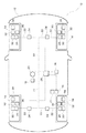
図1は、本実施の形態の車両10の全体構成を示す図である。タイヤの内部空気圧を監視する機構およびタイヤの内部空気圧を調整する機構を具備する本実施の形態の車両10は、車体12と、車体12の前後左右に設けられた車輪14と、を備えている。
(First embodiment)
FIG. 1 is a diagram showing an overall configuration of a
車体12には、車体側通信装置16と、警報装置18と、エアータンク19と、エアータンク19に接続されたエアーポンプ20と、タイヤ空気圧指示器21と、エアー管22を介してエアーポンプ20に連結された四つのエアー調整電磁弁24と、車体側通信装置16、警報装置18、タイヤ空気圧指示器21、エアーポンプ20、およびエアー調整電磁弁24に接続されたECU(電子制御装置)26と、が搭載されている。
The
車輪14は、内部に空気を封入したタイヤと、タイヤを支持するホイールとを含んで構成されている。各車輪14には、対応するエアー調整電磁弁24にエアー管22を介して連結されたタイヤ圧調整部28と、圧力検出センサ30と、圧力検出センサ30に接続された送信モード決定装置32と、送信モード決定装置32に接続された車輪側通信装置34と、が搭載されている。各車輪14に設けられている圧力検出センサ30、送信モード決定装置32、および車輪側通信装置34の各々は、同一の車輪14に搭載された電池(図示せず)が蓄えている電気エネルギーを利用して作動する。また、各車輪14に設けられている圧力検出センサ30、送信モード決定装置32、および車輪側通信装置34は、一体あるいは別体として構成することが可能である。
The
タイヤ圧調整部28は、タイヤの内部とエアー管22とを連結するバルブの役割を果たし、エアー調整電磁弁24から送られてくる空気を対応するタイヤの内部に封入し、また、対応するタイヤの内部の空気をエアー調整電磁弁24に送る。タイヤ圧調整部28は、連結されているエアー管22の内部の空気圧とタイヤの内部空気圧とが略等しくなるように調整する。
The tire
各圧力検出センサ30は、タイヤの内部空気圧を個別に監視することができるTPMS(タイヤ空気圧モニタリングシステム)を構成する。この圧力検出センサ30は、対応するタイヤの内部空気圧を定期的に検出して、検出結果を送信モード決定装置32に送る。本実施の形態の圧力検出センサ30は、15秒に1回の割合でタイヤの内部空気圧を検出して送信モード決定装置32に送る。
Each
送信モード決定装置32は、圧力検出センサ30から送られてくる検出結果に基づいて、車輪側通信装置34における送信モードを決定する。具体的には送信モード決定装置32は、圧力検出センサ30の検出結果から求められる所定時間あたりのタイヤの内部空気圧の変化量と予め定められている送信モード判定用閾値とを比較して、車輪側通信装置34における送信モードを決定する。本実施の形態では、1分に1回の割合という低頻度で圧力検出センサ30の検出結果を送信する通常送信モードと、15秒に1回の割合という高頻度で圧力検出センサ30の検出結果を送信する非常送信モードとによって、車輪側通信装置34における送信モードが構成されている。所定時間あたりのタイヤの内部空気圧の変化量が送信モード判定用閾値以下の値を示す場合には、タイヤの内部空気圧が正常な状態であると判断され、送信モード決定装置32は通常送信モードを送信モードとして決定する。一方、所定時間あたりのタイヤの内部空気圧の変化量が送信モード判定用閾値よりも大きな値を示す場合には、タイヤの内部空気圧に関し異常を生じている可能性があると判断され、送信モード決定装置32は非常送信モードを送信モードとして決定する。
The transmission
送信モード決定装置32は、後述するように車両ドライバー等の指示によってタイヤの内部空気圧を走行環境に合わせて積極的に調整する場合に、エアー調整電磁弁24などによってタイヤの内部空気圧の調整が実施されている間は、車輪側通信装置34による圧力検出センサ30の検出結果等の送信頻度が通常時よりも抑制されるようにする。本実施の形態の送信モード決定装置32は、上記の場合にエアー調整電磁弁24などがタイヤの内部空気圧の調整を実施している間は、車輪14の異常発生の判断条件となる送信モード判定用閾値を変更することによって、車輪側通信装置34における送信頻度を抑制する。具体的には、送信モード決定装置32は、タイヤの内部空気圧の調整が実施されていないと判断する場合には第1の送信モード判定用閾値を用いて送信モードを決定し、タイヤの内部空気圧の調整が実施されていると判断する場合には第1の送信モード判定用閾値よりも値が大きい第2の送信モード判定用閾値を用いて送信モードを決定する。第2の送信モード判定用閾値を用いる場合には、第1の送信モード判定用閾値を用いる場合に比べて、通常送信モードから非常送信モードへの切り換え頻度が少なくなり、結果として、車輪側通信装置34における送信頻度が全体的に抑制されることとなる。
The transmission
送信モード決定装置32は、第2の送信モード判定用閾値を用いることを決定した場合には、その決定時から所定時間が経過したら、第1の送信モード判定用閾値を用いるようになっている。この所定時間は、上記の場合にエアー調整電磁弁24などによってタイヤの内部空気圧の調整が実施されている間は第2の送信モード判定用閾値が送信モード決定装置32において用いられるように、定められることが好ましい。
When it is determined that the second transmission mode determination threshold value is used, the transmission
なお、送信モード決定装置32は、上記の場合にエアー調整電磁弁24などによってタイヤの内部空気圧の調整が実施されているのか否かを、圧力検出センサ30の検出結果に基づいて判断する。本実施の形態では、後述するように、上記の場合にエアー調整電磁弁24などによってタイヤの内部空気圧の調整が実施されていることの合図が、「タイヤの内部空気圧の挙動」によって車体12側の機器類から車輪14側の機器類に伝えられる。従って、送信モード決定装置32は、圧力検出センサ30の検出結果からタイヤの内部空気圧の挙動を判断し、送信モード判定用閾値として第1の送信モード判定用閾値および第2の送信モード判定用閾値のうちいずれを用いるべきか判断する。
The transmission
送信モード決定装置32は、決定した送信モードを、圧力検出センサ30の検出結果、タイヤの内部空気圧の調整の実施に関する上記合図の確認の有無、等の情報とともに車輪側通信装置34に送る。
The transmission
車輪側通信装置34は、送信モード決定装置32において判定された送信モードに基づいて、圧力検出センサ30の検出結果を車体側通信装置16に無線送信する。この時、車輪側通信装置34は、圧力検出センサ30の検出結果だけでなく、送信モードや、タイヤの内部空気圧を介して伝えられるエアー調整電磁弁24の運転状態を検知したか否かの確認に関する事項なども、ビットのかたちで表された情報として送信電波に含ませることが可能である。
The wheel
車体12に搭載された車体側通信装置16は、各車輪側通信装置34などから無線送信されてくる電波を受信して、電波に含まれている情報をECU26に送る。
The vehicle body
警報装置18は、ECU26により制御され、各車輪14の圧力検出センサ30、送信モード決定装置32、および車輪側通信装置34から伝えられる車輪14の異常発生の通知に基づき警報を発する。
The
タイヤ空気圧指示器21は、走行環境に応じてタイヤの内部空気圧を積極的に変えることにより快適な走行を確保したい場合に、走行環境に関する指示を、車両ドライバー等から受け付けてECU26に伝える。例えば高速道路などの舗装された路面を高速走行する場合や泥道などのぬかるんだ路面を走行する場合に、車両ドライバー等はそのような走行環境をタイヤ空気圧指示器21を介してECU26に伝える。
The tire
エアータンク19は、所定の圧力に圧縮された空気を貯留する。エアーポンプ20は、エアータンク19に貯留されている空気を、エアー管22を介して各エアー調整電磁弁24に向かって送る。
The
エアー調整電磁弁24は、各車輪14に対応するようにして設けられ、対応する車輪14のタイヤの内部空気圧を調整する電磁弁である。具体的には、エアー調整電磁弁24は、エアーポンプ20から送られてくる空気を、対応する車輪14のタイヤ圧調整部28を介してタイヤの内部に送ることによって、タイヤの内部空気圧を加圧する。また、エアー調整電磁弁24は、タイヤ圧調整部28を介してタイヤの内部から空気を吸引して外部に放出することによって、タイヤの内部空気圧を減圧する。
The air adjustment
エアーポンプ20およびエアー調整電磁弁24は、ECU26によって制御されており、圧力検出センサ30によるタイヤの内部空気圧の監視結果が参照されて、タイヤの内部空気圧の調整を実施する。なお、エアーポンプ20およびエアー調整電磁弁24によるタイヤの内部空気圧の加圧あるいは減圧に関する情報は、ECU26に記憶されるようになっている。
The
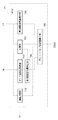
ECU26は、車体側通信装置16、タイヤ空気圧指示器21、あるいは図示しない電子機器類等から送られてくる情報に基づいて、エアーポンプ20、エアー調整電磁弁24、警報装置18、等の各種機器類を制御し、車両10の様々な状態をコントロールする。本実施の形態のECU26は、図2に示すような各種機能を有している。
The
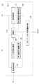
図2は、ECU26が有する各種機能のうちタイヤの内部空気圧の監視や調整に関する機能を示す機能ブロック図である。ECU26は、記憶部102、タイヤ空気圧判断部103、第1調整空気量算出部104、第2調整空気量算出部106、ポンプ/バルブ制御量算出部108、および警報判定部110を有している。
FIG. 2 is a functional block diagram showing functions related to monitoring and adjustment of the tire internal air pressure among various functions of the
記憶部102は、車輪側通信装置34および車体側通信装置16を介して送られてくる圧力検出センサ30の検出結果を、検出時刻あるいは送受信時刻とともに記憶する。また記憶部102は、車輪側通信装置34および車体側通信装置16を介して送られてくるその他の情報についても記憶する。更に記憶部102は、エアーポンプ20およびエアー調整電磁弁24を駆動制御することによって調整するタイヤの内部空気圧の加圧あるいは減圧に関する情報を記憶し、例えば各タイヤに対する供給空気量や排出空気量などを記憶する。
The memory |
タイヤ空気圧判断部103は、車体側通信装置16から送られてくる圧力検出センサ30の検出結果に基づいて、タイヤの内部空気圧が標準的な空気圧から外れているか否かを判断する。ここでいう「標準的な空気圧」は、車両10のタイプに応じて適宜決定されるものであり、例えば通常走行時に適切な車両走行を確保することができる範囲の空気圧を指す。
The tire air
第1調整空気量算出部104は、タイヤ空気圧判断部103においてタイヤの内部空気圧が標準的な空気圧から外れていると判断される場合に、タイヤの内部空気圧を標準的な空気圧に戻すのに必要とされるタイヤ内部への供給空気量あるいはタイヤ内部からの排出空気量を、圧力検出センサ30の検出結果に基づいて算出する。この時、第1調整空気量算出部104は、記憶部102に記憶されている各種情報を適宜参照することができる。タイヤ内部への供給空気量あるいはタイヤ内部からの排出空気量の算出結果は、第1調整空気量算出部104からポンプ/バルブ制御量算出部108に送られる。
The first adjustment air
第2調整空気量算出部106は、タイヤ空気圧指示器21から送られてくる走行環境に関する指示信号に基づいて、タイヤの内部空気圧をその走行環境に応じた空気圧に変えるために必要とされるタイヤ内部への供給空気量あるいはタイヤ内部からの排出空気量を算出する。この時、第2調整空気量算出部106は、記憶部102に記憶されている各種情報を適宜参照することができる。タイヤ内部への供給空気量あるいはタイヤ内部からの排出空気量の算出結果は、第2調整空気量算出部106からポンプ/バルブ制御量算出部108に送られる。
The second adjustment air
ポンプ/バルブ制御量算出部108は、第1調整空気量算出部104あるいは第2調整空気量算出部106の算出結果に基づいて、エアーポンプ20の稼働状態やエアー調整電磁弁24の調整量を算出する。そして、ポンプ/バルブ制御量算出部108は、算出したエアーポンプ20の稼働状態やエアー調整電磁弁24の調整量に基づく制御信号を、エアーポンプ20や対応するエアー調整電磁弁24に送る。エアーポンプ20やエアー調整電磁弁24は、ポンプ/バルブ制御量算出部108から送られてくる制御信号に応じて作動する。
The pump / valve control
また、ポンプ/バルブ制御量算出部108は、第2調整空気量算出部106の算出結果に基づく場合には、タイヤの内部空気圧の状態を操作することによって各車輪14に設けられた圧力検出センサ30や送信モード決定装置32などに「合図」が伝わるように、エアーポンプ20の稼働状態やエアー調整電磁弁24の調整量を算出する。すなわち、エアー調整電磁弁24などによってタイヤの内部空気圧の調整が実施されることの「合図」が、「タイヤの内部空気圧の変化」という形態で、車体側に設けられたECU26等から車輪側に設けられた圧力検出センサ30や送信モード決定装置32等に伝えられるように、エアーポンプ20の稼働状態やエアー調整電磁弁24の調整量がポンプ/バルブ制御量算出部108において求められる。本実施の形態では、第2調整空気量算出部106における算出結果に基づいてタイヤの内部空気圧を加圧したい場合に、ポンプ/バルブ制御量算出部108は、タイヤの内部空気圧が一旦減圧された後に加圧されるような制御信号をエアーポンプ20やエアー調整電磁弁24に送る。また、第2調整空気量算出部106における算出結果に基づいてタイヤの内部空気圧を減圧したい場合には、ポンプ/バルブ制御量算出部108は、タイヤの内部空気圧が一旦加圧された後に減圧されるような制御信号をエアーポンプ20や対応するエアー調整電磁弁24に送る。このようなタイヤの内部空気圧の「加圧→減圧」に関する挙動あるいは「減圧→加圧」に関する挙動は、通常はとらない振る舞いとなるように、所定の時間の間に生じさせられる。このようなタイヤの内部空気圧の振る舞いは、圧力検出センサ30によって検出されて、送信モード決定装置32に伝えられることとなる。
In addition, the pump / valve control
なお、エアー調整電磁弁24などによってタイヤの内部空気圧の調整が実施されることの「合図」が圧力検出センサ30等に対して適切に伝わるように、圧力検出センサ30によるタイヤの内部空気圧の検出タイミングや送信モード決定装置32における送信モードの決定基準などが考慮されて「合図」が決定される。例えば、上記の「合図」を示唆するタイヤの内部空気圧の一連の挙動が非常に短い期間に実施されると、15秒という圧力検出センサ30の検出インターバルの間に上記の「合図」が埋もれてしまうおそれがあり、圧力検出センサ30によって「合図」が検出されないという事態が生じうる。そのため、圧力検出センサ30による複数回のタイヤ内部空気圧の検出によって、上記の「合図」を示唆するタイヤの内部空気圧の一連の挙動が適切に把握されるように、上記の「合図」を示唆するタイヤの内部空気圧の挙動タイミングや期間が決定される。また例えば、上記の「合図」を示唆するタイヤの内部空気圧の一連の挙動を検知するために少なくとも5回分の圧力検出センサ30の検出結果が必要とされる場合、送信モード決定装置32が圧力検出センサ30の3回分の検出結果に基づいて送信モードを決定してしまうと、上記の「合図」が考慮されずに送信モードが決定されてしまうおそれがある。そのような事態を防ぐために、送信モード決定装置32が送信モードを決定してしまう前に、上記の「合図」を示唆するタイヤの内部空気圧の一連の挙動が圧力検出センサ30によって検出されるように、上記の「合図」を示唆するタイヤの内部空気圧の挙動タイミングや期間が決定される。
Note that the
警報判定部110は、各車輪14の圧力検出センサ30、送信モード決定装置32、および車輪側通信装置34によって通知される車輪14の異常発生の有無に基づいて、警報装置18を作動させる。本実施の形態では、タイヤの内部空気圧の絶対値や変化量に基づいて、車輪14の異常発生の有無が判断される。タイヤの内部空気圧の絶対値や変化量が正常な範囲の値を示す場合には車輪14に異常が発生していないと判断され、警報判定部110は警報装置18を作動させない。一方、タイヤの内部空気圧の絶対値や変化量が正常な範囲から外れる値を示す場合には、車輪14に異常が発生していると判断され、警報判定部110は警報装置18を作動させる。なお、タイヤの内部空気圧の絶対値や変化量は、車輪側通信装置34から送られてくる圧力検出センサ30の検出結果から導き出される。
The
上述のような構成を有する本実施の形態において、タイヤの内部空気圧に関して異常が発生しているか否かは圧力検出センサ30によって監視されている。また、タイヤの内部空気圧に関して異常が発生しているおそれがあるか否かは、圧力検出センサ30の検出結果から導き出されるタイヤの内部空気圧の絶対値や変化量によって判断されている。そして、送信モード決定装置32および車輪側通信装置34によって、圧力検出センサ30の検出結果が車体側に設けられた車体側通信装置16やECU26に通知される。そのため、車輪14の状態量の一つであるタイヤの内部空気圧を監視して車輪14の異常発生を通知する車輪状態監視手段が、圧力検出センサ30、送信モード決定装置32、車輪側通信装置34を含んで構成されている。また、タイヤの内部空気圧の調整を実施する車輪状態調整手段が、エアーポンプ20、タイヤ空気圧指示器21、エアー管22、エアー調整電磁弁24、およびECU26を含んで構成されている。
In the present embodiment having the above-described configuration, whether or not an abnormality has occurred with respect to the internal air pressure of the tire is monitored by the
次に、上述の構成によって実現される本実施の形態の車輪状態調整システムの作用について説明する。 Next, the operation of the wheel state adjustment system of the present embodiment realized by the above configuration will be described.
まず、通常の車両走行時について説明する。 First, normal vehicle traveling will be described.
通常の車両走行時には、タイヤの内部空気圧が圧力検出センサ30によって定期的に検出され、送信モード決定装置32において決定される送信モードに従って車輪側通信装置34から車体側通信装置16に送信される。このとき、例えばタイヤの内部空気の自然漏れ等によってタイヤの内部空気圧が比較的緩やかに変化している場合には、タイヤの内部空気圧の検出結果等が通常送信モードで車輪側通信装置34から車体側通信装置16に送信される。また、パンクなどのためにタイヤの内部空気圧が急激に変化する場合には、タイヤの内部空気圧の検出結果等が異常送信モードで車輪側通信装置34から車体側通信装置16に送信される。
During normal vehicle travel, the tire internal air pressure is periodically detected by the
車体側通信装置16が受信した電波に含まれる圧力検出センサ30の検出結果等の情報はECU26に送られる。ECU26では、車体側通信装置16から送られてくる圧力検出センサ30の検出結果等の情報が記憶部102に記憶されるとともに、タイヤの内部空気圧が標準的な状態から逸脱した状態であるか否かがタイヤ空気圧判断部103において判断される。タイヤの内部空気圧が標準的な状態から逸脱していないと判断される場合には、タイヤの内部空気圧の監視が続行される。
Information such as the detection result of the
一方、タイヤの内部空気圧が標準的な状態から逸脱していると判断される場合には、タイヤの内部空気圧を標準的な状態に戻すために必要とされるタイヤ内部への供給空気量あるいはタイヤ内部からの排出空気量が、第1調整空気量算出部104において算出される。そして、算出されたタイヤ内部への供給空気量あるいはタイヤ内部からの排出空気量に基づいて、エアーポンプ20の稼働状態やエアー調整電磁弁24の調整量がポンプ/バルブ制御量算出部108において算出され、制御信号がポンプ/バルブ制御量算出部108からエアーポンプ20やエアー調整電磁弁24に送られる。このようにして、タイヤの内部空気量はエアーポンプ20やエアー調整電磁弁24によって調節され、タイヤの内部空気圧が標準的な状態に保持されるように調整される。
On the other hand, if it is determined that the internal air pressure of the tire deviates from the standard state, the amount of air supplied into the tire or the tire required to return the internal air pressure of the tire to the standard state The amount of air discharged from the inside is calculated by the first adjusted air
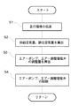
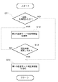
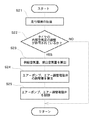
次に、図3および図4を参照して、車両10の走行環境に合わせてタイヤの内部空気圧が調整される場合について説明する。図3および図4は、車両10の走行環境に合わせてタイヤの内部空気圧を調整する過程を示すフローチャートであり、図3は主に車体側の装置類の処理を示し、図4は主に車輪側の装置類の処理を示す。
Next, with reference to FIG. 3 and FIG. 4, a case where the internal air pressure of the tire is adjusted in accordance with the traveling environment of the
まず、車両10の走行環境が車両ドライバー等によりタイヤ空気圧指示器21を介してECU26に伝えられる(図3のS1)。ECU26では、車両10の走行環境に適したタイヤ空気圧とするために必要とされるタイヤ内部への供給空気量あるいはタイヤ内部からの排出空気量が第2調整空気量算出部106において算出される(S2)。
First, the traveling environment of the
そして、タイヤ内部への供給空気量あるいはタイヤ内部からの排出空気量の算出結果に基づいて、エアーポンプ20の稼働状態やエアー調整電磁弁24の調整量がポンプ/バルブ制御量算出部108において算出され、制御信号がポンプ/バルブ制御量算出部108からエアーポンプ20やエアー調整電磁弁24に送られる(S3)。エアーポンプ20やエアー調整電磁弁24は、送られてくる制御信号に基づいて駆動制御され、タイヤの内部空気量が調節されて、車両10の走行環境に応じた空気圧にタイヤの内部空気圧が調整される(S4)。
Based on the calculation result of the amount of air supplied to the inside of the tire or the amount of air discharged from the inside of the tire, the operating state of the
このとき、エアーポンプ20およびエアー調整電磁弁24は、ECU26のポンプ/バルブ制御量算出部108からの制御信号に基づいてタイヤの内部空気量を調整し、タイヤの内部空気圧の調整が実施されることの「合図」が、タイヤの内部空気圧を介して圧力検出センサ30や送信モード決定装置32に伝えられる。例えば、走行環境に合わせてタイヤの内部空気圧をやや高めに設定したい場合には、タイヤの内部空気圧が一旦減圧された後に加圧される。同様に、タイヤの内部空気圧をやや低めに設定したい場合には、タイヤの内部空気圧が一旦加圧された後に減圧される。タイヤの内部空気圧の挙動は、圧力検出センサ30によって検出され、上記の合図を検知したか否かが送信モード決定装置32において判定される(図4のS11)。上記の合図が送信モード決定装置32において検知された場合には(S11のYES)、エアー調整電磁弁24などによってタイヤの内部空気圧の調整が実施されていると判断され、第2の送信モード判定用閾値が用いられる(S12)。これにより車輪側通信装置34から車体側通信装置16への送信頻度が抑制されることとなる。第2の送信モード判定用閾値が用いられる場合には(S12)、第2の送信モード判定用閾値を用いるようになってから所定時間が経過したか否かが送信モード決定装置32において判定される(S13)。所定時間が経過していない場合には(S13のNO)、送信モード決定装置32では第2の送信モード判定用閾値が引き続き用いられる。一方、所定時間が経過した場合には(S13のYES)、エアー調整電磁弁24などによるタイヤの内部空気圧の調整の実施が終了したものと判断され、送信モード判定用閾値として第1の送信モード判定用閾値が用いられる(S14)。
At this time, the
上記の「合図」が送信モード決定装置32によって検知されない場合には(S11のNO)、エアー調整電磁弁24などによるタイヤの内部空気圧の調整は実施されていないと判断され、送信モード決定装置32では、第1の送信モード判定用閾値が用いられる(S14)。
If the above “cue” is not detected by the transmission mode determination device 32 (NO in S11), it is determined that the internal air pressure of the tire is not adjusted by the air adjustment
なお、パンク等のためにタイヤの内部空気圧に関して異常が発生しているおそれがある場合には、ECU26の警報判定部110が、車輪側通信装置34および車体側通信装置16を介して送られてくる圧力検出センサ30の検出結果を参照して警報装置18を作動させる。警報装置18は、警報音や警告ランプなどによって車両ドライバー等の注意を喚起し、タイヤの内部空気圧に関する異常を通知する。
In addition, when there is a possibility that an abnormality has occurred with respect to the internal air pressure of the tire due to puncture or the like, the
以上説明したように本実施の形態によれば、タイヤの内部空気圧が走行環境に合わせて積極的に調整される場合に、エアー調整電磁弁24などによってタイヤの内部空気圧の調整が実施されている間は第2の送信モード判定用閾値が用いられるので、車輪側通信装置34の送信モードが通常送信モードから異常送信モードに切り替わりにくくなっている。これにより、例えばタイヤに異常が発生していないにもかかわらず、タイヤの内部空気圧の調整によるタイヤの内部空気圧の変化を「タイヤの異常発生によるものである」と誤って判断してしまうことを防ぎ、車輪側通信装置34から車体側通信装置16への車輪14の異常発生についての誤通知を防止することができる。そして、車輪側通信装置34における送信頻度を適正に保つことができ、タイヤの内部空気圧の異常発生に関する通知頻度を抑制することができる。このように車輪側通信装置34からの通知頻度を抑制することにより、車輪側通信装置34の通知に伴う電力消費量を節約することができ、電池の長寿命化を図ることできる。
As described above, according to the present embodiment, when the internal air pressure of the tire is positively adjusted according to the driving environment, the internal air pressure of the tire is adjusted by the air adjustment
また、タイヤの内部空気圧の振る舞いによって、タイヤの内部空気圧の調整が実施されていることの「合図」を車体側の機器類から車輪側の機器類に伝えることにより、そのような「合図」を伝えるための特別の機器類の設置等が不要である。特に、そのような「合図」として、「通常はとらない振る舞い」をタイヤの内部空気圧が示すようにすることによって、「エアー調整電磁弁24などによるタイヤの内部空気圧の調整による空気圧変化」と「タイヤの損傷や走行環境などによってもたらされるタイヤの内部空気圧の変化」とを明確に区別することができ、「合図」に関する誤検出を防ぐことができる。
In addition, by transmitting a “sign” that the internal pressure of the tire is being adjusted by the behavior of the tire's internal air pressure from the vehicle-side equipment to the wheel-side equipment, such a “sign” is transmitted. There is no need to install special equipment to communicate. In particular, as such a “sign”, the “air pressure change by adjusting the internal air pressure of the tire by the air adjusting
また、本実施の形態では、圧力検出センサ30によるタイヤの内部空気圧の監視結果を参照したタイヤの内部空気圧の調整の実施も行われており、パンク等の損傷や走行環境によってもたらされる不具合も精度良く検出することが可能である。
Further, in the present embodiment, the adjustment of the tire internal air pressure is also performed by referring to the monitoring result of the tire internal air pressure by the
なお、上述の実施の形態では、タイヤの内部空気圧を走行環境に合わせて積極的に調整する際に車輪14の異常発生の通知頻度を抑制する場合について説明したが、本発明はそれに限定されるものではない。例えば、タイヤの内部空気圧を標準的な状態に保つために、圧力検出センサ30の検出結果に基づいてエアー調整電磁弁24などによりタイヤの内部空気圧を調整する場合にも、上述と同様にして、車輪側通信装置34などからの車輪14の異常発生の通知頻度を抑制することが可能である。
In the above-described embodiment, the case where the notification frequency of occurrence of abnormality of the
(第2の実施の形態)
本実施の形態において、上述の第1の実施の形態と同一部分には同一符号を付して詳細な説明は省略する。
(Second Embodiment)
In the present embodiment, the same parts as those in the first embodiment are denoted by the same reference numerals, and detailed description thereof is omitted.
図5は、本実施の形態の車両10の全体構成を示す図である。本実施の形態では、車両10の速度を検出する車速検出センサ35が各車輪14に搭載されている。車速検出センサ35は、車両10の速度を直接的にあるいは間接的に検出することができる任意の構成をとることが可能であり、例えば車輪14の回転速度を検出するセンサの検出結果から間接的に車両10の速度を検出するものであってもよい。この車速検出センサ35は、送信モード決定装置32に接続されており、検出結果を送信モード決定装置32に送る。
FIG. 5 is a diagram showing an overall configuration of the
送信モード決定装置32は、車速検出センサ35から送られてくる車両速度の値に応じてON−OFFするGスイッチ(図示せず)を含んで構成されている。Gスイッチは、車速検出センサ35が所定の速度以上の車両速度を検出した場合にON状態となり、所定の速度よりも小さい車両速度を検出した場合にはOFF状態となる。GスイッチがONの状態になると、送信モード決定装置32は、上述の第1の実施の形態の場合と同様にして送信モードを決定する。GスイッチがOFFの状態になると、送信モード決定装置32は、圧力検出センサ30の検出結果にかかわらず、常に通常送信モードを送信モードとして決定する。
The transmission
上記の「所定の速度」は、GスイッチのON−OFF状態を切り換える基準、および車輪側通信装置34の送信モードを通常送信モードに固定するか否かの基準となり、また後述するようにタイヤの内部空気圧の積極的な調整を許可するか禁止するかの判断基準にもなる。そのため、この「所定の速度」は、通常送信モードに固定したりタイヤの内部空気圧の積極的な調整を許可したりしても不都合が生じない範囲の速度が参照されて定められており、本実施の形態では不具合が比較的少ない低速度に設定されている。
The above-mentioned “predetermined speed” is a reference for switching the ON / OFF state of the G switch and a reference for determining whether or not the transmission mode of the wheel
車輪側通信装置34は、送信モード決定装置32において決定された送信モードにしたがって圧力検出センサ30の検出結果等を車体側通信装置16に送信する。本実施の形態では、タイヤの内部空気圧の積極的な調整を許可するか否かを示す調整可否情報も、各車輪側通信装置34から車体側通信装置16に送信される。GスイッチがON状態となっている場合には、車輪側通信装置34から送信される電波に「タイヤの内部空気圧の積極的な調整を禁止する調整可否情報」が含められる。一方、GスイッチがOFF状態にある場合には、車輪側通信装置34から送信される電波に「タイヤの内部空気圧の積極的な調整を許可する調整可否情報」が含められる。
The wheel
各車輪側通信装置34から車体側通信装置16に送られる電波には、圧力検出センサ30の検出結果等に加えて調整可否情報も含められる。車体側通信装置16が受信した電波に含まれる各種情報は、ECU26に送られて、ECU26の記憶部102に記憶される。
The radio wave transmitted from each wheel
図6は、本実施の形態のECU26が有する各種機能のうちタイヤの内部空気圧の監視や調整に関する機能を示す機能ブロック図である。ECU26は、記憶部102および第2調整空気量算出部106に接続された指令判定部112を更に有しており、タイヤ空気圧指示器21から送られてくる走行環境に関する指示信号は、指令判定部112に伝えられる。
FIG. 6 is a functional block diagram showing functions relating to monitoring and adjustment of the internal air pressure of the tire among the various functions of the
指令判定部112は、タイヤ空気圧指示器21から走行環境に関する指示信号が送られてきた場合には、記憶部102に記憶されている調整可否情報を参照して、タイヤの内部空気圧の積極的な調整が許可されているのか禁止されているのかを確認する。タイヤの内部空気圧の調整が禁止されている場合には、タイヤの内部空気圧の積極的な調整が行われず、必要に応じてその旨を車両ドライバー等に通知する。一方、タイヤの内部空気圧の調整が許可されている場合には、タイヤの内部空気圧の積極的な調整が行われることとなり、タイヤ空気圧指示器21から送られてきた走行環境に関する情報が指令判定部112から第2調整空気量算出部106に伝えられる。
When an instruction signal related to the driving environment is sent from the
他の構成は、図1乃至図4に示す第1の実施の形態と略同一である。 Other configurations are substantially the same as those of the first embodiment shown in FIGS.
車両10の走行環境に合わせてタイヤの内部空気圧を調整する場合について、図7を参照して説明する。図7は、車両10の走行環境に合わせてタイヤの内部空気圧を調整する過程を示すフローチャートである。
A case where the internal air pressure of the tire is adjusted in accordance with the traveling environment of the
まず、車両10の走行環境が車両ドライバー等によりタイヤ空気圧指示器21を介してECU26の指令判定部112に伝えられる(図7のS21)。指令判定部112では、記憶部102に記憶されている調整可否情報を参照して、タイヤの内部空気圧の積極的な調整が許可されているか禁止されているかが判定される(S22)。タイヤの内部空気圧の積極的な調整が禁止されている場合には(S22のNO)、エアー調整電磁弁24などによるタイヤの内部空気圧の積極的な調整を実施することができない。一方、タイヤの内部空気圧の積極的な調整が許可されている場合には(S22のYES)、エアー調整電磁弁24などによるタイヤの内部空気圧の積極的な調整が実施される。すなわち、車両10の走行環境に適したタイヤ空気圧とするために必要とされるタイヤ内部への供給空気量あるいはタイヤ内部からの排出空気量が第2調整空気量算出部106において算出され(S23)、エアーポンプ20の稼働状態やエアー調整電磁弁24の調整量がポンプ/バルブ制御量算出部108において算出される(S24)。そして、エアーポンプ20やエアー調整電磁弁24は、ポンプ/バルブ制御量算出部108から送られてくる制御信号に基づいて駆動制御される(S25)。これにより、タイヤの内部空気量が調節されて、車両10の走行環境に応じた空気圧にタイヤの内部空気圧が調整される。
First, the traveling environment of the
以上説明したように本実施の形態では、車両の速度が参照されてタイヤの内部空気圧の調整が実施されており、車両速度が低速でGスイッチがOFFの状態にある場合にのみ、タイヤの内部空気圧の積極的な調整が行われる。そのため、不具合が比較的少ない低速度の車両速度の場合にのみ、タイヤの内部空気圧の積極的な調整が行われることとなる。そして、タイヤの内部空気圧の調整が行われている間は、送信モードが通常送信モードに固定されているので、車輪側通信装置34などからの車輪14の異常発生の通知頻度を抑制することができる。
As described above, in the present embodiment, the internal pressure of the tire is adjusted with reference to the vehicle speed, and only when the vehicle speed is low and the G switch is in the OFF state, Active adjustment of air pressure is performed. Therefore, positive adjustment of the tire internal air pressure is performed only when the vehicle speed is low and the number of defects is relatively low. Since the transmission mode is fixed to the normal transmission mode while the internal air pressure of the tire is being adjusted, it is possible to suppress the notification frequency of the occurrence of the abnormality of the
なお、上述の実施の形態では車速検出センサ35が車輪14に設けられている例について説明したが、車体12に車速検出センサ35を設けることも可能である。その場合には、例えば、車速検出センサ35の検出結果をECU26に有線で送信することができ、タイヤの内部空気圧の積極的な調整を実施することができるか否かをECU26の指令判定部112において判断するようにすることもできる。また、送信モード決定装置32によって適切な送信モードを決定させるために、第1の実施の形態における場合と同様にして、「タイヤの内部空気圧の振る舞い」により車両速度が「所定の速度」以上か否かを各車輪14の送信モード決定装置32に伝えて、GスイッチのON−OFF状態を切り換えるようにすることもできる。
In the above-described embodiment, the example in which the vehicle
(第3の実施の形態)
本実施の形態において、上述の第1の実施の形態と同一部分には同一符号を付して詳細な説明は省略する。
(Third embodiment)
In the present embodiment, the same parts as those in the first embodiment are denoted by the same reference numerals, and detailed description thereof is omitted.
本実施の形態では、車輪側通信装置34は、車体側通信装置16に電波を送信するだけでなく、車体側通信装置16から送られてくる電波を受信する機能を有している。また、車体側通信装置16は、各車輪側通信装置34から送られてくる電波を受信するだけでなく、各車輪側通信装置34に向かって電波を送信する機能を有している。
In the present embodiment, the wheel
図8は、本実施の形態のECU26が有する各種機能のうちタイヤの内部空気圧の監視や調整に関する機能を示す機能ブロック図である。ECU26は、ポンプ/バルブ制御量算出部108に接続された送信モード制御部114を更に有している。送信モード制御部114は、ポンプ/バルブ制御量算出部108の算出結果に基づいて、各エアー調整電磁弁24の作動情報を対応する車体側通信装置16に送るようになっている。
FIG. 8 is a functional block diagram showing functions related to monitoring and adjustment of the internal air pressure of the tire among various functions of the
車体側通信装置16は、ECU26の送信モード制御部114から送られてくる各エアー調整電磁弁24の作動情報を、対応する車輪側通信装置34に送信する。車輪側通信装置34は、車体側通信装置16から送られてくるエアー調整電磁弁24の作動情報を、対応する送信モード決定装置32に送る。送信モード決定装置32は、車輪側通信装置34から送られてくるエアー調整電磁弁24の作動情報に基づいて、使用する送信モード判定用閾値を決定する。すなわち、エアー調整電磁弁24が作動していない場合には第1の送信モード判定用閾値が用いられ、また、エアー調整電磁弁24が作動している場合には第2の送信モード判定用閾値を用いられるようになっている。
The vehicle body
他の構成は、図1乃至図4に示す第1の実施の形態と略同一である。 Other configurations are substantially the same as those of the first embodiment shown in FIGS.
本実施の形態では、例えば、車両10の走行環境が車両ドライバー等によりタイヤ空気圧指示器21を介してECU26に伝えられると、ECU26では、各タイヤに対する供給空気量あるいは排出空気量、およびエアーポンプ20の稼働状態やエアー調整電磁弁24の調整量が算出されて、エアーポンプ20やエアー調整電磁弁24に制御信号が送られる。また、ポンプ/バルブ制御量算出部108の算出結果から導き出されるエアー調整電磁弁24の作動情報が、ECU26の送信モード制御部114から車体側通信装置16および車輪側通信装置34を介して対応する送信モード決定装置32に送られる。これにより、エアー調整電磁弁24によってタイヤの内部空気圧の調整が積極的に行われている時には、送信モード決定装置32では第1の送信モード判定用閾値が用いられ、また、エアー調整電磁弁24によってタイヤの内部空気圧の調整が積極的に行われていない時には、送信モード決定装置32では第2の送信モード判定用閾値が用いられることとなる。
In the present embodiment, for example, when the traveling environment of the
また、圧力検出センサ30の検出結果に基づきタイヤの内部空気圧を標準的な状態に保つためにタイヤの内部空気圧を調整する場合にも、上述と同様にして、エアー調整電磁弁24の作動情報がECU26の送信モード制御部114から車輪側通信装置34に送られ、第1の送信モード判定用閾値あるいは第2の送信モード判定用閾値のいずれが用いられるのか決定される。
Also, when adjusting the tire internal air pressure in order to keep the tire internal air pressure in a standard state based on the detection result of the
以上説明したように本実施の形態では、車体側の機器類と各車輪側の機器類との間で双方向に無線通信で情報のやりとりがされて、車輪側通信装置34の送信モードの判断基準である送信モード判定用閾値が決定される。これにより、エアー調整電磁弁24が作動してタイヤの内部空気圧が調整されている間は、第2の送信モード判定用閾値が用いられて、車輪14の異常発生の通知頻度の抑制が図られ、車輪側通信装置34の送信に伴う電力消費量を節約することができる。
As described above, in this embodiment, information is exchanged bidirectionally between the vehicle body side devices and the wheel side devices via wireless communication, and the determination of the transmission mode of the wheel
本発明は、上述の各実施の形態や各変形例に限定されるものではなく、上述の各実施の形態や各変形例における各要素を適宜組み換えることによっても、本発明の実施の形態を実現することが可能である。また、当業者の知識に基づいて各種の設計変更等の変形を加えることも可能であり、そのような変形が加えられた実施の形態も本発明の範囲に含まれうるものである。 The present invention is not limited to the above-described embodiments and modifications, and the embodiments of the present invention can also be achieved by appropriately recombining the elements in the above-described embodiments and modifications. It is possible to realize. Various modifications such as design changes can be added based on the knowledge of those skilled in the art, and embodiments to which such modifications are added can also be included in the scope of the present invention.
例えば、上述の実施の形態では、車輪側通信装置34の送信モードの判断基準である送信モード判定用閾値を変更することによって、車輪側通信装置34などによるタイヤの内部空気圧に関する異常発生の通知が抑制されているが、他の手法を用いることもできる。例えば、エアー調整電磁弁24などの車輪状態調整手段がタイヤの内部空気圧の調整を実施している間は、車輪側通信装置34による圧力検出センサ30の検出結果等の送信を停止して異常発生の通知を停止することにより、車輪側通信装置34などによるタイヤの内部空気圧に関する異常発生の通知頻度を抑制することもできる。この場合、送信モード決定装置32では、送信モード判定用閾値を変更する代わりに、圧力検出センサ30の検出結果に基づいて、車輪側通信装置34における情報の定期的な送信を継続するか停止するかが決定される。そして、車輪側通信装置34は、対応する送信モード決定装置32から送られてくる「情報の定期的な送信を継続するか停止するかの決定」に基づいて、圧力検出センサ30の検出結果等の送信を行う。
For example, in the above-described embodiment, by changing the transmission mode determination threshold value that is the determination criterion of the transmission mode of the wheel-
また、上述の実施の形態では、例えばタイヤの内部空気圧を加圧する場合には所定の時間の間にタイヤの内部空気圧を一旦減圧した後に加圧することにより、エアー調整電磁弁24などによってタイヤの内部空気圧の調整が実施されることの「合図」が実現されている例を説明したが、これに限定されるものではない。例えば、タイヤの内部空気圧の調整が実施されることの「合図」を、タイヤの内部空気圧を断続的に加圧したり減圧したりすることによって実現することも可能である。このような場合には、タイヤの内部空気圧が通常の車両走行時にはとらない振る舞いを示すように、エアーポンプ20やエアー調整電磁弁24が制御されることが好ましい。
Further, in the above-described embodiment, for example, when the internal air pressure of the tire is increased, the internal air pressure of the tire is once reduced for a predetermined time and then pressurized, thereby the internal pressure of the tire is adjusted by the air adjustment
また、上述の実施の形態では、車両ドライバー等の指示があった場合にタイヤの内部空気圧を走行環境に応じて積極的に変える例について説明したが、これに限定されるものではない。例えば車両10の走行状態を車両速度センサやカメラなどによって検知し、当該検知結果から自動的に走行環境を判断してタイヤの内部空気圧を変えるような場合であっても、本発明を適用することが可能である。
Moreover, although the above-mentioned embodiment demonstrated the example which changes the internal air pressure of a tire positively according to driving | running | working environment, when there exists instruction | indication of a vehicle driver etc., it is not limited to this. For example, the present invention is applied even when the traveling state of the
また、上述の第1の実施の形態および第2の実施の形態では、第2の送信モード判定用閾値が用いられて車輪側通信装置34の送信モードが決定される場合には、その決定時から所定時間が経過したか否かによって、送信モード判定用閾値を第1の送信モード判定用閾値に戻すか否かを判定する場合について説明したが、これに限定されるものではない。例えば、エアー調整電磁弁24などによるタイヤの内部空気圧の調整が終了した時点で、当該調整が終了したことの合図を送信モード決定装置32に伝えることにより、送信モード決定装置32は送信モード判定用閾値を第2の送信モード判定用閾値から第1の送信モード判定用閾値に戻すか否かを判定することも可能である。なお、「タイヤの内部空気圧の調整が終了したことの合図」は、上述した「タイヤの内部空気圧の調整が実施されることの合図」と同様に、タイヤの内部空気圧の振る舞いによって、車体側の機器類から車輪側の送信モード決定装置32に伝えることが可能である。
Further, in the first embodiment and the second embodiment described above, when the transmission mode of the wheel
また、上述の各実施の形態では、車輪14の異常発生の有無がタイヤの内部空気圧の絶対値や変化量によって判断される例について説明したが、これに限定されるものではない。例えば車輪側通信装置34の送信モードの違いや送信頻度に基づいて、車輪14の異常発生の有無を判断することも可能である。車体側通信装置16から送られてくる情報に車輪側通信装置34の送信モードが通常送信モードであることが含まれていたり、車輪側通信装置34から車体側通信装置16への送信頻度が比較的少ない場合には、車輪14に異常が発生していないと判断され、警報判定部110は警報装置18を作動させないようにすることもできる。また、車体側通信装置16から送られてくる情報に車輪側通信装置34の送信モードが異常送信モードであることが含まれていたり、車輪側通信装置34から車体側通信装置16への送信頻度が比較的多い場合には、車輪14に異常が発生していると判断され、警報判定部110は警報装置18を作動させることもできる。
Further, in each of the above-described embodiments, the example in which the presence / absence of abnormality of the
10 車両、 12 車体、 14 車輪、 16 車体側通信装置、 18 警報装置、 20 エアーポンプ、 21 タイヤ空気圧指示器、 22 エアー管、 24 エアー調整電磁弁、 26 ECU、 28 タイヤ圧調整部、 30 圧力検出センサ、 32 送信モード決定装置、 34 車輪側通信装置、 35 車速検出センサ、 102 記憶部、 103 タイヤ空気圧判断部、 104 第1調整空気量算出部、 106 第2調整空気量算出部、 108 ポンプ/バルブ制御量算出部、 110 警報判定部、 112 指令判定部、 114 送信モード制御部 10 vehicle, 12 vehicle body, 14 wheel, 16 vehicle body side communication device, 18 alarm device, 20 air pump, 21 tire pressure indicator, 22 air pipe, 24 air adjusting solenoid valve, 26 ECU, 28 tire pressure adjusting unit, 30 pressure Detection sensor, 32 transmission mode determination device, 34 wheel side communication device, 35 vehicle speed detection sensor, 102 storage unit, 103 tire air pressure determination unit, 104 first adjustment air amount calculation unit, 106 second adjustment air amount calculation unit, 108 pump / Valve control amount calculation unit, 110 Alarm determination unit, 112 Command determination unit, 114 Transmission mode control unit
Claims (9)
前記車輪の所定状態量の調整を実施する車輪状態調整手段と、を備え、
前記車輪状態監視手段は、前記車輪状態調整手段が前記車輪の所定状態量の調整を実施している間は、前記車輪の異常発生の通知頻度を抑制することを特徴とする車輪状態調整システム。 A wheel state monitoring means for monitoring a predetermined state amount of the wheel and notifying the occurrence of an abnormality of the wheel;
Wheel state adjusting means for adjusting the predetermined state quantity of the wheel, and
The wheel state monitoring system, wherein the wheel state adjustment unit suppresses the notification frequency of occurrence of abnormality of the wheel while the wheel state adjustment unit is adjusting the predetermined state amount of the wheel.
Priority Applications (3)
| Application Number | Priority Date | Filing Date | Title |
|---|---|---|---|
| JP2004119152A JP2005297851A (en) | 2004-04-14 | 2004-04-14 | Wheel condition adjustment system |
| US11/094,410 US7259663B2 (en) | 2004-04-14 | 2005-03-31 | Wheel state adjustment system and method thereof |
| EP05007317A EP1586467A1 (en) | 2004-04-14 | 2005-04-04 | Wheel state adjustment system and method thereof |
Applications Claiming Priority (1)
| Application Number | Priority Date | Filing Date | Title |
|---|---|---|---|
| JP2004119152A JP2005297851A (en) | 2004-04-14 | 2004-04-14 | Wheel condition adjustment system |
Publications (1)
| Publication Number | Publication Date |
|---|---|
| JP2005297851A true JP2005297851A (en) | 2005-10-27 |
Family
ID=34934737
Family Applications (1)
| Application Number | Title | Priority Date | Filing Date |
|---|---|---|---|
| JP2004119152A Pending JP2005297851A (en) | 2004-04-14 | 2004-04-14 | Wheel condition adjustment system |
Country Status (3)
| Country | Link |
|---|---|
| US (1) | US7259663B2 (en) |
| EP (1) | EP1586467A1 (en) |
| JP (1) | JP2005297851A (en) |
Cited By (1)
| Publication number | Priority date | Publication date | Assignee | Title |
|---|---|---|---|---|
| JP2011016462A (en) * | 2009-07-09 | 2011-01-27 | Nissan Motor Co Ltd | Tire air pressure detector, tire air pressure monitoring system, and tire air pressure transmitting method |
Families Citing this family (14)
| Publication number | Priority date | Publication date | Assignee | Title |
|---|---|---|---|---|
| JP4435114B2 (en) * | 2006-05-31 | 2010-03-17 | トヨタ自動車株式会社 | Tire risk judgment device for vehicle wheels |
| US8392048B2 (en) * | 2006-11-30 | 2013-03-05 | Hunter Engineering Company | Integrated tire pressure diagnostic system and method |
| JP4232821B2 (en) * | 2006-12-06 | 2009-03-04 | トヨタ自動車株式会社 | Pneumatic control system and pneumatic control device |
| US20100212798A1 (en) * | 2009-02-20 | 2010-08-26 | Nissan Technical Center North America, Inc. | Tire pressure inflation system |
| US8688324B2 (en) * | 2009-11-19 | 2014-04-01 | Freescale Semiconductor, Inc. | Pump system and motorized vehicle |
| US20110203710A1 (en) * | 2010-02-24 | 2011-08-25 | Mesa Digital, Llc | Automatic tire pressure control and monitoring system and method |
| DE102011081682B4 (en) * | 2011-08-26 | 2019-01-31 | Robert Bosch Gmbh | drive system |
| US8680981B2 (en) * | 2011-12-07 | 2014-03-25 | E-Lead Electronic Co., Ltd. | Tire pressure display device and its detection method |
| CN102632776A (en) * | 2012-04-26 | 2012-08-15 | 江苏大学 | Pressure monitoring and automatic air-charging device for vehicle tires |
| CN103770585B (en) * | 2013-10-10 | 2016-03-23 | 广西科技大学 | A kind of vehicle tire pressure control apparatus |
| CN103770581B (en) * | 2013-10-10 | 2016-03-23 | 广西科技大学 | Vehicle tire pressure control apparatus intelligent control system |
| CN104802606A (en) * | 2015-05-21 | 2015-07-29 | 天津市航翔科技发展有限公司 | Civil-military dual use novel central tire inflation/deflation system |
| GB2540414A (en) * | 2015-07-16 | 2017-01-18 | Airbus Operations Ltd | Tyre pressure sensor device |
| US10124634B2 (en) * | 2016-12-13 | 2018-11-13 | Fz Engineering Inc. | Tire pressure monitoring system emulation device and method |
Family Cites Families (11)
| Publication number | Priority date | Publication date | Assignee | Title |
|---|---|---|---|---|
| US5587698A (en) * | 1992-02-05 | 1996-12-24 | Genna; Robert A. | Automatic tire pressure control system for a vehicle |
| FR2699277A1 (en) | 1992-12-11 | 1994-06-17 | Michelin & Cie | A method of controlling the tire pressure of a vehicle |
| JPH07137515A (en) | 1993-11-18 | 1995-05-30 | Toyota Motor Corp | Abnormality detection device for tire pressure control device |
| DE19522486C2 (en) * | 1995-06-21 | 1999-04-22 | Duerrwaechter E Dr Doduco | Method for operating a device for monitoring and wireless signaling of a pressure change in pneumatic tires on vehicles |
| JP3344919B2 (en) * | 1997-03-07 | 2002-11-18 | 住友電気工業株式会社 | Tire pressure drop detector |
| JP2000099869A (en) * | 1998-09-21 | 2000-04-07 | Toyota Motor Corp | Tire pressure monitor |
| US6144295A (en) * | 1998-12-11 | 2000-11-07 | Case Corporation | Automatic central tire inflation system |
| DE19961020A1 (en) | 1999-12-17 | 2000-06-21 | Post Dieter | Automatic tire air pressure control with integrated tire defect elimination for all cars is operated electronically in next to no time from inside car and whole system is joined rigidly with car |
| US6518877B1 (en) | 2001-05-31 | 2003-02-11 | The Goodyear Tire & Rubber Company | Pneumatic tire monitor |
| FR2836656B1 (en) * | 2002-03-01 | 2004-05-28 | Michelin Soc Tech | DEVICE AND METHOD FOR THE TREATMENT OF PRESSURE LOSS AND FLAT ROLLING PHENOMENA OF VEHICLE TIRES |
| JP3997864B2 (en) | 2002-08-14 | 2007-10-24 | トヨタ自動車株式会社 | Wheel state acquisition device and vehicle state acquisition device |
-
2004
- 2004-04-14 JP JP2004119152A patent/JP2005297851A/en active Pending
-
2005
- 2005-03-31 US US11/094,410 patent/US7259663B2/en not_active Expired - Fee Related
- 2005-04-04 EP EP05007317A patent/EP1586467A1/en not_active Withdrawn
Cited By (1)
| Publication number | Priority date | Publication date | Assignee | Title |
|---|---|---|---|---|
| JP2011016462A (en) * | 2009-07-09 | 2011-01-27 | Nissan Motor Co Ltd | Tire air pressure detector, tire air pressure monitoring system, and tire air pressure transmitting method |
Also Published As
| Publication number | Publication date |
|---|---|
| EP1586467A1 (en) | 2005-10-19 |
| US7259663B2 (en) | 2007-08-21 |
| US20050231344A1 (en) | 2005-10-20 |
Similar Documents
| Publication | Publication Date | Title |
|---|---|---|
| JP4232821B2 (en) | Pneumatic control system and pneumatic control device | |
| JP2005297851A (en) | Wheel condition adjustment system | |
| CN102405145B (en) | Tire Air Pressure Monitoring Device | |
| JP5191887B2 (en) | Tire monitoring system | |
| JP3960112B2 (en) | Tire condition detection / communication device | |
| US8005589B2 (en) | Method and system for addressing improper towing of a vehicle | |
| US8125322B2 (en) | Vehicle-mounted malfunction notification apparatus and vehicle-mounted malfunction notification method | |
| US20060249323A1 (en) | Wheel condition determination apparatus | |
| JP2000355203A (en) | Tire air pressure alarm device | |
| JP2000016037A (en) | Tire pressure information transmission / reception device | |
| JP2008120275A (en) | Wheel condition monitoring system | |
| CN104057789B (en) | Device for monitoring tire air pressure | |
| JP4082345B2 (en) | Wheel state detection device, wheel and vehicle body | |
| JP2017087941A (en) | Tire air pressure detection system | |
| JP2009119887A (en) | Tire pressure monitoring device | |
| JP6234912B2 (en) | Tire condition detection device | |
| JP4076290B2 (en) | Tire condition monitoring device | |
| JP2008013145A (en) | Tire air pressure monitoring device | |
| JP2000203218A (en) | Tire condition monitoring unit | |
| JP2005104410A (en) | Tire pressure monitoring device and tire pressure monitoring system | |
| JP2006069414A (en) | Tire air pressure detecting device | |
| JP4223439B2 (en) | Tire condition monitoring device and tire damage notification method | |
| JP3914782B2 (en) | Tire pressure warning device | |
| KR100680348B1 (en) | Vehicle tire pressure monitoring system and control method thereof | |
| JP2008112372A (en) | Wheel condition monitoring system and wheel information transmitting device |
Legal Events
| Date | Code | Title | Description |
|---|---|---|---|
| A621 | Written request for application examination |
Free format text: JAPANESE INTERMEDIATE CODE: A621 Effective date: 20060629 |
|
| A977 | Report on retrieval |
Free format text: JAPANESE INTERMEDIATE CODE: A971007 Effective date: 20080125 |
|
| A131 | Notification of reasons for refusal |
Free format text: JAPANESE INTERMEDIATE CODE: A131 Effective date: 20080624 |
|
| A521 | Written amendment |
Free format text: JAPANESE INTERMEDIATE CODE: A523 Effective date: 20080807 |
|
| A131 | Notification of reasons for refusal |
Free format text: JAPANESE INTERMEDIATE CODE: A131 Effective date: 20081111 |
|
| A02 | Decision of refusal |
Free format text: JAPANESE INTERMEDIATE CODE: A02 Effective date: 20090317 |