JP2005297831A - Seat slide mechanism - Google Patents
Seat slide mechanism Download PDFInfo
- Publication number
- JP2005297831A JP2005297831A JP2004118532A JP2004118532A JP2005297831A JP 2005297831 A JP2005297831 A JP 2005297831A JP 2004118532 A JP2004118532 A JP 2004118532A JP 2004118532 A JP2004118532 A JP 2004118532A JP 2005297831 A JP2005297831 A JP 2005297831A
- Authority
- JP
- Japan
- Prior art keywords
- seat
- slide rail
- seating
- slide
- range
- Prior art date
- Legal status (The legal status is an assumption and is not a legal conclusion. Google has not performed a legal analysis and makes no representation as to the accuracy of the status listed.)
- Pending
Links
Images


Landscapes
- Seats For Vehicles (AREA)
Abstract
【課題】 スライドレールの断面形状を一定としたまま着座規制ができるようにする。
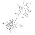
【解決手段】 車室1内にシート3を車両前後方向2へスライド可能に設けたシートスライド機構において、設定した着座範囲22以外の位置では、シート3のシートクッション部4が跳ね上げ状態となるよう構成している。
【選択図】 図1
PROBLEM TO BE SOLVED: To enable seating restriction while keeping a cross-sectional shape of a slide rail constant.
In a seat slide mechanism in which a seat 3 is slidable in a vehicle front-rear direction 2 in a passenger compartment 1, a seat cushion portion 4 of the seat 3 is flipped up at a position other than a set seating range 22. It is configured as follows.
[Selection] Figure 1
Description
この発明は、シートスライド機構に関するものである。 The present invention relates to a seat slide mechanism.
自動車などの車両では、車室内に車両前後方向へスライド可能にシートが取付けられている。シートをスライドさせるシートスライド機構は、車室内に車両前後方向へ敷設されたスライドレールと、シートに取付けられてスライドレールにスライド嵌合されるシートライナーと、スライドレールに車両前後方向に沿って多数形成されたシートロック孔と、シートライナーに取付けられてシートロック孔に対して嵌合離脱可能なスライドロックとを備えている(例えば、特許文献1〜3参照)。
しかしながら、上記特許文献1、2に記載されたシートスライド機構では、長尺のスライドレールに対し任意の位置でシートをロックできるようにしていたため、シートベルトの対応範囲外においても乗員が着座できてしまうという問題があった。
However, in the seat slide mechanism described in
また、上記特許文献3に記載されたシートスライド機構では、着座規制のために、シートの着座範囲とそれ以外の範囲とでスライドレールの断面形状を変えて一定でなくしていたので、スライドレールを一体押出構造とすることができず、コストや重量の面で不利になるという問題があった。
Further, in the seat slide mechanism described in
上記課題を解決するために、本発明では、車室内にシートを車両前後方向へスライド可能に設けたシートスライド機構において、設定した着座範囲以外の位置では、シートのシートクッション部が跳ね上げ状態となるよう構成されたシートスライド機構を特徴としている。 In order to solve the above problems, in the present invention, in a seat slide mechanism in which a seat is slidable in the vehicle front-rear direction in a vehicle interior, the seat cushion portion of the seat is in a flipped-up state at a position other than the set seating range. It is characterized by a seat slide mechanism configured as described above.
この発明によれば、設定した着座範囲以外の位置では、シートのシートクッション部が跳ね上げ状態となるよう構成されたことにより、着座範囲以外では着座できないようにすることができる。以て、シートベルトの対応範囲外での着座規制を行うことが可能となる。 According to the present invention, the seat cushion portion of the seat is in the flipped-up state at a position other than the set seating range, so that the seat cannot be seated outside the seating range. Therefore, it is possible to perform seating regulation outside the corresponding range of the seat belt.
スライドレールの断面形状を一定としたまま着座規制ができるようにするという目的を、スライドレールの着座範囲に車両前後方向へ延びる長孔を形成すると共に、長孔への嵌合時にシートクッション部が着座可能状態となり、長孔への非嵌合時にシートクッション部が跳ね上げ状態となるよう構成された着座位置規制アームをシートライナーに設ける、という手段で実現した。 For the purpose of enabling seating regulation while keeping the cross-sectional shape of the slide rail constant, a long hole extending in the vehicle front-rear direction is formed in the seating range of the slide rail, and the seat cushion portion is fitted to the long hole. The seat liner is provided with a seating position restricting arm configured to be in a seatable state and to be in a state in which the seat cushion part is flipped up when not fitted into the long hole.
以下、本発明を具体化した実施例について、図示例と共に説明する。 Embodiments of the present invention will be described below together with illustrated examples.
図1〜図10は、この発明の実施例を示すものである。 1 to 10 show an embodiment of the present invention.
まず、構成を説明すると、図1に示すように、自動車などの車両では、車室1内に車両前後方向2へスライド可能にシート3が取付けられている。このシート3は、乗員の腰部を下方から支持するシートクッション部4と、乗員の背部を後方から支持するシートバック部5と、乗員の頭部を後方から支持可能なヘッドレスト部6とを備えている。
First, the configuration will be described. As shown in FIG. 1, in a vehicle such as an automobile, a
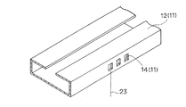
上記したシート3をスライドさせるシートスライド機構11は、車室1内に略車両前後方向2へ敷設されたスライドレール12と、図2に示すように、シート3に取付けられてスライドレール12にスライド嵌合されるシートライナー13と、図3、図4に示すように、スライドレール12に車両前後方向2に沿って多数形成されたシートロック孔14と、図2に示すように、シートライナー13に取付けられてシートロック孔14に対して嵌合離脱可能なスライドロック15とを備えている。
The above-described
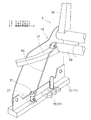
ここで、図2に示すように、シート3は、シートクッション部4の内部に設けられたシートクッションフレーム17と、シートバック部5の内部に設けられたシートバックフレーム18とをシート支持フレーム19で支持する構造を備えており、シートライナー13は、シート支持フレーム19の下部に取付けられている。シートライナー13は、ほぼ逆T字状を呈している。また、スライドロック15は、図示しないレバーなどによって操作されるよう構成されている。一方、図3、図4に示すように、スライドレール12は、例えば、上側がスリット状に開放されたC字チャンネル状などを呈している。また、シートロック孔14は、図1に示すように、着座範囲22(と対応する位置)や着座範囲22以外の位置(例えば、シート格納位置23など)に適宜設定される。シートロック孔14は、例えば、C字チャンネル状のスライドレール12の一側面に形成する。
Here, as shown in FIG. 2, the
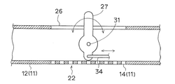
この実施例のものでは、図1に示すように、設定した着座範囲22以外の位置では、シート3におけるシートクッション部4が跳ね上げ状態となるよう構成する。そのために、先ず、図2に示すように、シートクッションフレーム17を、シート支持フレーム19に対して回動自在となるように軸支する(回動中心軸24)。なお、シートバックフレーム18も、シートバック部5がリクライニングし得るように、シート支持フレーム19に対して回動自在に軸支されている。
In this embodiment, as shown in FIG. 1, the
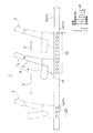
そして、図3に示すように、スライドレール12の着座範囲22(と対応する位置)に対してのみ車両前後方向2へ延びる長孔26を形成すると共に、図5、図6に示すように、長孔26への嵌合時にシートクッション部4が着座可能状態となり、長孔26への非嵌合時にシートクッション部4が跳ね上げ状態となるよう構成された着座位置規制アーム27を、シートライナー13に設ける。
And as shown in FIG. 3, while forming the
ここで、図3に示すように、長孔26は、例えば、C字チャンネル状のスライドレール12の他側面に形成する。図2に示すように、着座位置規制アーム27は、シートライナー13に回動自在に軸支された縦軸31に対して半径方向へ所要の長さで延設されている。そして、この縦軸31の軸心から偏心した位置とシートクッションフレーム17の回動中心から偏心した位置との間にロッド34を連結してシート跳ね上げ機構を構成し、このシート跳ね上げ機構によって、シートクッション部4の跳ね上げ動作に連動して着座位置規制アーム27が回動されて長孔26とは非嵌合となり、また、シートクッション部4の跳ね上げ状態からの戻し動作に連動して着座位置規制アーム27が逆方向に回動されて長孔26へ嵌合されるようにする。
Here, as shown in FIG. 3, the
更に、図10に示すように、スライドレール12を車室1の前部から後部に亘る長さの長尺物とし(ロングスライドレール37)、長尺のスライドレール12における、前席(いわゆる最前列シート)と中間席(いわゆるセカンドシート)と後席(いわゆるサードシートまたは3列目シート)とに対応する着座範囲22にそれぞれ長孔26を形成する。なお、特に図示していないが、このロングスライドレール37に対して、図1に示すようなシート格納位置23などを設定することもできる。
Further, as shown in FIG. 10, the
次に、この実施例の作用について説明する。 Next, the operation of this embodiment will be described.
この実施例によれば、設定した着座範囲22以外の位置では、シート3のシートクッション部4が跳ね上げ状態となるよう構成されたことにより、着座範囲22以外では着座できないようにすることができる。以て、シートベルトの対応範囲外での着座規制を行うことが可能となる。
According to this embodiment, the
より具体的には、スライドレール12の着座範囲22に車両前後方向2へ延びる長孔26を形成すると共に、長孔26への嵌合時にシートクッション部4の着座可能状態となり、長孔26への非嵌合時にシートクッション部4が跳ね上げ状態となるよう構成された着座位置規制アーム27をシートライナー13に設けたことにより、着座範囲22以外では着座できないようにし、シートベルトの対応範囲外での着座規制を行うことができるようになる。しかも、スライドレール12の断面形状は一定のままで良い。
More specifically, a
上記をより詳しく説明すると、シート3が着座範囲22にある場合に、図5、図7に示すように、シートクッション部4を着座可能状態(非跳ね上げ状態)とすると、ロッド34を介して着座位置規制アーム27が回動されて長孔26へ嵌合される。この状態では、シート3の移動は、着座位置規制アーム27と長孔26との干渉が生じない範囲内に規制されることとなる。即ち、シート3は、着座範囲22のみでの移動・固定が可能となる。反対に、着座範囲22以外への移動・固定はできない。なお、シートクッション部4を跳ね上げ状態とすることもできる。
More specifically, when the
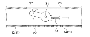
そして、シート3が着座範囲22にある場合に、図6、図8に示すように、シートクッション部4を跳ね上げ状態とすると、ロッド34を介して着座位置規制アーム27が上記とは反対方向に回動されて長孔26とは非嵌合となる。この状態では、シート3の移動は、何ら規制されないこととなる。即ち、シート3は、着座範囲22および着座範囲22以外への移動・固定が可能となる。なお、着座範囲22内に限りシートクッション部4を着座可能状態(非跳ね上げ状態)とすることもできる。
Then, when the
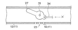
更に、シート3が着座範囲22以外にある場合には、図9に示すように、長孔26がないため、着座位置規制アーム27は長孔26に対して非嵌合の状態となり、シートクッション部4は跳ね上げ状態に保持される。この状態では、シート3の移動は、何ら規制されないこととなる。即ち、シート3は、着座範囲22および着座範囲22以外への移動・固定が可能である。但し、シートクッション部4を着座可能状態(非跳ね上げ状態)とすることはできない。
Further, when the
そして、スライドレール12を車室1の前部から後部に亘る長さの長尺物とし(ロングスライドレール37)、長尺のスライドレール12における、前席と中間席と後席とに対応する着座範囲22にそれぞれ長孔26を形成したことにより、1本のスライドレール12(ロングスライドレール37)で前席と中間席と後席との全てを独立してスライドさせることが可能となり、以て、部品点数を削減することができる。しかも、構造上、スライドレール12の断面形状を全長に亘って一定とすることができるので、スライドレール12を一体押出構造として、重量やコストを削減することが可能となる。
The
以上、この発明の実施例を図面により詳述してきたが、実施例はこの発明の例示にしか過ぎないものであるため、この発明は実施例の構成にのみ限定されるものではなく、この発明の要旨を逸脱しない範囲の設計の変更等があってもこの発明に含まれることは勿論である。 Although the embodiments of the present invention have been described in detail with reference to the drawings, the embodiments are only examples of the present invention, and the present invention is not limited to the configurations of the embodiments. Needless to say, design changes and the like within a range not departing from the gist of the invention are included in the present invention.
1 車室
2 車両前後方向
3 シート
4 シートクッション部
12 スライドレール
13 シートライナー
14 シートロック孔
15 スライドロック
22 着座範囲
26 長孔
27 着座位置規制アーム27
DESCRIPTION OF
Claims (3)
設定した着座範囲以外の位置では、シートのシートクッション部が跳ね上げ状態となるよう構成したことを特徴とするシートスライド機構。 In a seat slide mechanism that is slidable in the vehicle longitudinal direction in the vehicle interior,
A seat slide mechanism characterized in that the seat cushion portion of the seat is in a flipped-up state at a position other than the set seating range.
スライドレールに車両前後方向に沿ってシートロック孔を多数形成すると共に、シートライナーに前記シートロック孔に対して嵌合離脱可能なスライドロックを取付け、
更に、スライドレールの着座範囲に車両前後方向へ延びる長孔を形成すると共に、該長孔への嵌合時にシートクッション部が着座可能状態となり、前記長孔への非嵌合時にシートクッション部が跳ね上げ状態となるよう構成された着座位置規制アームをシートライナーに設けたことを特徴とする請求項1記載のシートスライド機構。 A slide rail extending in the vehicle longitudinal direction is laid in the vehicle interior, and a seat liner that is slidably fitted to the slide rail is attached to the seat.
A number of seat lock holes are formed on the slide rail along the longitudinal direction of the vehicle, and a slide lock that can be fitted to and detached from the seat lock hole is attached to the seat liner.
Furthermore, a long hole extending in the vehicle front-rear direction is formed in the seating range of the slide rail, and the seat cushion portion can be seated when fitted into the long hole, and the seat cushion portion is not fitted into the long hole. 2. The seat slide mechanism according to claim 1, wherein a seating position restricting arm configured to be in a flip-up state is provided on the seat liner.
Priority Applications (1)
| Application Number | Priority Date | Filing Date | Title |
|---|---|---|---|
| JP2004118532A JP2005297831A (en) | 2004-04-14 | 2004-04-14 | Seat slide mechanism |
Applications Claiming Priority (1)
| Application Number | Priority Date | Filing Date | Title |
|---|---|---|---|
| JP2004118532A JP2005297831A (en) | 2004-04-14 | 2004-04-14 | Seat slide mechanism |
Publications (1)
| Publication Number | Publication Date |
|---|---|
| JP2005297831A true JP2005297831A (en) | 2005-10-27 |
Family
ID=35329893
Family Applications (1)
| Application Number | Title | Priority Date | Filing Date |
|---|---|---|---|
| JP2004118532A Pending JP2005297831A (en) | 2004-04-14 | 2004-04-14 | Seat slide mechanism |
Country Status (1)
| Country | Link |
|---|---|
| JP (1) | JP2005297831A (en) |
-
2004
- 2004-04-14 JP JP2004118532A patent/JP2005297831A/en active Pending
Similar Documents
| Publication | Publication Date | Title |
|---|---|---|
| US9283873B2 (en) | Flex and fold vehicle seating assembly | |
| US7484786B2 (en) | Adjustable rear seat | |
| JP2018075892A (en) | Vehicle seat | |
| JP4569823B2 (en) | Vehicle seat | |
| JP2005297831A (en) | Seat slide mechanism | |
| US7255395B2 (en) | Seat assembly with movable inner seat back | |
| JP2008284950A (en) | Vehicle seat device | |
| JP4622760B2 (en) | Vehicle seat device | |
| JP5516253B2 (en) | Rear cargo compartment structure of vehicle | |
| JP7239803B2 (en) | vehicle seat | |
| JP4023425B2 (en) | Car | |
| JP4380417B2 (en) | Vehicle seat device | |
| JP4192693B2 (en) | Vehicle seat structure | |
| JP2009035022A (en) | Vehicle seat device | |
| JP3870805B2 (en) | Vehicle seat device | |
| JP2008279893A (en) | Vehicle seat device | |
| JP4192694B2 (en) | Vehicle seat structure | |
| JP4200826B2 (en) | Vehicle seat structure | |
| JP2024003230A (en) | vehicle seat | |
| JP2007253669A (en) | Vehicle seat device | |
| JP2018079860A (en) | Vehicle seat | |
| JP2006306251A (en) | Car seat | |
| JP2007076394A (en) | Vehicle seat device | |
| JP5445911B2 (en) | Structure of vehicle seat | |
| JP3783638B2 (en) | Vehicle seat device |
Legal Events
| Date | Code | Title | Description |
|---|---|---|---|
| A621 | Written request for application examination |
Free format text: JAPANESE INTERMEDIATE CODE: A621 Effective date: 20070402 |
|
| A977 | Report on retrieval |
Free format text: JAPANESE INTERMEDIATE CODE: A971007 Effective date: 20090513 |
|
| A131 | Notification of reasons for refusal |
Free format text: JAPANESE INTERMEDIATE CODE: A131 Effective date: 20090519 |
|
| A02 | Decision of refusal |
Free format text: JAPANESE INTERMEDIATE CODE: A02 Effective date: 20091006 |