JP2005297796A - Anti-theft device and anti-theft method - Google Patents
Anti-theft device and anti-theft method Download PDFInfo
- Publication number
- JP2005297796A JP2005297796A JP2004117733A JP2004117733A JP2005297796A JP 2005297796 A JP2005297796 A JP 2005297796A JP 2004117733 A JP2004117733 A JP 2004117733A JP 2004117733 A JP2004117733 A JP 2004117733A JP 2005297796 A JP2005297796 A JP 2005297796A
- Authority
- JP
- Japan
- Prior art keywords
- vehicle
- intelligent key
- engine
- parking brake
- control unit
- Prior art date
- Legal status (The legal status is an assumption and is not a legal conclusion. Google has not performed a legal analysis and makes no representation as to the accuracy of the status listed.)
- Pending
Links
Images
Landscapes
- Lock And Its Accessories (AREA)
Abstract
【課題】 車両の防盗性能のよい防盗装置を提供する。
【解決手段】 車両が停止状態であり、かつエンジンが作動した状態で、乗員がシフトレバー10AをPレンジに設定してパーキングブレーキを引き、インテリジェントキー3を所持したまま車両から離れた場合には、インテリジェントキーコントロールユニット1からの指示によりATデバイス10がシフトロックを行い、さらにパーキングブレーキ11がパーキングブレーキを作動状態でロックする。これにより、車両のエンジンは作動状態ではあるが、シフトロックおよびパーキングブレーキのロックが行われていることにより、インテリジェントキー3を所持した乗員以外の人物によって車両を移動させることが不可能となり、車両の防盗性能が向上する。
【選択図】 図1PROBLEM TO BE SOLVED: To provide an antitheft device having a high antitheft performance for a vehicle.
When a vehicle is in a stopped state and an engine is operated, an occupant sets a shift lever 10A to a P range, applies a parking brake, and leaves the vehicle while holding an intelligent key 3. In response to an instruction from the intelligent key control unit 1, the AT device 10 performs a shift lock, and the parking brake 11 locks the parking brake in an activated state. Thereby, although the engine of the vehicle is in an operating state, the vehicle cannot be moved by a person other than the passenger who has the intelligent key 3 because the shift lock and the parking brake are locked. The anti-theft performance improves.
[Selection] Figure 1
Description
本発明は、車両用電子キーシステムにおける携帯機と車載機との間で無線通信を行い、車両のエンジンを始動可能とする防盗装置および防盗方法に関する。 The present invention relates to a burglarproof device and a burglarproof method that enable wireless communication between a portable device and a vehicle-mounted device in a vehicle electronic key system to start a vehicle engine.
従来、車両のドアの開閉やエンジンの始動を行うインテリジェントキーシステム(電子キーシステム)を用いた防盗装置がある。これはID登録されたインテリジェントキーを乗員が携帯して、乗員が車両周囲の所定領域以内に近づいたときに、インテリジェントキーと車両に搭載されたインテリジェントキーユニットとの双方向通信による電子式ID照合を行い、その結果をもとに施錠解除制御やエンジンの始動制御を可能とするものである。
エンジンの始動制御は、イグニッションノブが押されるとインテリジェントキーとインテリジェントキーユニット間でID照合が行われ、ID番号が整合すれば、インテリジェントキーユニットからの信号によって、イグニッションノブの回転禁止機構が解除されて、イグニッションノブが回転可能となる。
2. Description of the Related Art Conventionally, there is an antitheft device using an intelligent key system (electronic key system) that opens and closes a vehicle door and starts an engine. This is an electronic ID verification based on bidirectional communication between the intelligent key and the intelligent key unit installed in the vehicle when the passenger carries the ID-registered intelligent key and the passenger approaches within a predetermined area around the vehicle. And unlocking control and engine start control are enabled based on the result.
When starting the engine, the ID key is checked between the intelligent key and intelligent key unit when the ignition knob is pressed. If the ID number matches, the rotation control mechanism of the ignition knob is canceled by the signal from the intelligent key unit. Thus, the ignition knob can be rotated.
また同時に、インテリジェントキーユニットからスタータインヒビターリレーに向けてオン信号を送信し、スタータモータを始動可能な状態にする。
この状態で、乗員がイグニションノブをSTART位置(エンジン始動位置)まで回すことにより、エンジンを始動することができる。
また、イグニッションノブが回転可能な状態では車速が5km/h以下の時に、30秒毎にインテリジェントキーとインテリジェントキーユニットとの間でID照合を行い、照合結果がNGの場合(インテリジェントキーが見つからなかった場合)に、インテリジェントキーが車内に無いことを知らせる警報ブザーを鳴らしていた。
In this state, the passenger can start the engine by turning the ignition knob to the START position (engine start position).
In addition, when the ignition knob is rotatable and the vehicle speed is 5 km / h or less, ID verification is performed between the intelligent key and the intelligent key unit every 30 seconds. If the verification result is NG (the intelligent key is not found) Alarm buzzer sounding that the intelligent key is not in the car.
しかしながら、このような従来の防盗装置においては、イグニッションノブが押された時に実行されたID照合にもとづいて、エンジンの始動可否を判断するといった機能を有するが、たとえばエンジンの始動後にインテリジェントキーを携帯したまま乗員が車両を離れた場合には、インテリジェントキーが車内にないことを知らせる警報ブザーは鳴るもののエンジンは作動状態であり、車両が移動可能な状態のまま放置され、車両の防盗性能が劣るといった問題があった。 However, such a conventional antitheft device has a function of determining whether or not the engine can be started based on the ID collation performed when the ignition knob is pressed. For example, the intelligent key is carried after the engine is started. If the occupant leaves the vehicle while the alarm buzzer is left, an alarm buzzer sounds that the intelligent key is not in the vehicle, but the engine is in operation and the vehicle is left in a movable state, resulting in poor anti-theft performance of the vehicle. There was a problem.
そこで本発明はこのような問題点に鑑み、車両の防盗性能のよい防盗装置および防盗方法を提供することを目的とする。 Therefore, in view of such a problem, an object of the present invention is to provide a burglarproof device and a burglarproof method with good vehicle burglarproof performance.
本発明は、車両用電子キーシステムにおける携帯機と車載機との間で無線通信を行い、車両のエンジンを始動可能とする防盗装置であって、携帯機存在判定手段によって、車両内に携帯機があるかどうかを判定し、携帯機が無いと判定された場合には、作動禁止手段によってエンジン以外の所定機器の作動を禁止するものとした。 The present invention relates to an antitheft device capable of starting a vehicle engine by performing wireless communication between a portable device and an in-vehicle device in an electronic key system for a vehicle. When it is determined that there is no portable device, the operation prohibiting means prohibits the operation of a predetermined device other than the engine.
本発明によれば、車両内に携帯機が無い場合すなわち携帯機を携帯した乗員が車両の外にいる場合に、作動禁止手段によってエンジン以外の所定機器の作動を禁止することにより、作動を禁止された所定機器により車両の移動が困難となり、車両の防盗性能を向上させることができる。 According to the present invention, when there is no portable device in the vehicle, that is, when an occupant carrying the portable device is outside the vehicle, the operation is prohibited by prohibiting the operation of a predetermined device other than the engine by the operation prohibiting means. It is difficult for the vehicle to move due to the predetermined device, and the anti-theft performance of the vehicle can be improved.
次に本発明の実施の形態を実施例により説明する。
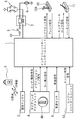
図1に、防盗装置の全体構成を示す。
本実施例における防盗装置の制御を集中的に行うインテリジェントキーコントロールユニット1に、インテリジェントキー3と無線通信を行うために用いられる室内アンテナ2が接続される。
インテリジェントキーコントロールユニット1は、室内アンテナ2を介してインテリジェントキー3にID要求を行い、インテリジェントキー3はインテリジェントキーコントロールユニット1からID要求があると、あらかじめ登録されているID情報を発信する。インテリジェントキーコントロールユニット1はインテリジェントキー3より発信されたID情報を室内アンテナ2を介して受信する。
Next, embodiments of the present invention will be described by way of examples.
FIG. 1 shows the overall configuration of the antitheft device.
An
The intelligent key control unit 1 makes an ID request to the intelligent key 3 via the
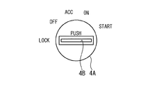
インテリジェントキーコントロールユニット1には、イグニッションノブ4Aが備えられたステアリングロックユニット4が接続される。
ステアリングロックユニット4は、図2に示すようにイグニッションノブ4AがLOCK位置の時、インテリジェントキーコントロールユニット1からのロック信号によりイグニッションノブ4AをLOCK位置に固定する。なお、図示しないステアリングは、イグニッションノブ4AがLOCK位置にあるときに機械的にロック状態となる。
またイグニッションノブ4Aには、図示しないメカニカルキーを挿入するためのメカニカルキー挿入口4Bが設けられている。
The intelligent key control unit 1 is connected to a
As shown in FIG. 2, when the
Further, the
図1に戻り、ステアリングロックユニット4は、イグニッションノブ4Aが押されることによってオン状態となるイグニッションノブ信号、およびメカニカルキーがメカニカルキー挿入口4Bに挿入されているときにオン状態となるキー挿入信号をインテリジェントキーコントロールユニット1に出力する。
Returning to FIG. 1, the
インテリジェントキーコントロールユニット1には、図示しないエンジンの始動を行うスタータモータ8の電源供給のオンオフ切り替えを行うスタータインヒビターリレー7が接続される。
さらにスタータインヒビターリレー7には、イグニッションノブ4AがSTART位置にあるときにオン状態となるキースイッチ5と、後述のATデバイス10のシフトポジションがNレンジまたはPレンジの時にオン状態となるインヒビタースイッチ6とが接続される。
よってスタータインヒビターリレー7は、インヒビタースイッチ6がオン状態であり、かつイグニッションノブ4AがSTART位置となったとき、さらにインテリジェントキーコントロールユニット1からスタータモータ8を作動させる作動信号が出されているときにオン状態となり、スタータモータ8を始動させる。
Connected to the intelligent key control unit 1 is a starter inhibitor relay 7 for switching on / off the power supply of a
Furthermore, the starter inhibitor relay 7 includes a key switch 5 that is turned on when the
Therefore, the starter inhibitor relay 7 is activated when the inhibitor switch 6 is in the ON state and the
インテリジェントキーコントロールユニット1に、車両の速度を検出する車速センサ9が接続され、車速センサ9によって検出された車速信号はインテリジェントキーコントロールユニット1へ出力される。
またインテリジェントキーコントロールユニット1に、エンジンの制御を行うエンジンコントロールユニット12が接続され、エンジンが始動中であることを知らせるためのエンジン状態信号がインテリジェントキーコントロールユニット1へ出力される。
A
An
インテリジェントキーコントロールユニット1に、シフトロック機能を有するATデバイス10と、パーキングロック機能を有するパーキングブレーキ11が接続される。
ATデバイス10は、シフトポジションがPレンジの時にPレンジ信号を出力するとともに、インテリジェントキーコントロールユニット1からのシフトロック信号によりシフトレバー10AをPレンジ位置に固定する。
またパーキングブレーキ11は、パーキングブレーキが引かれている(パーキングブレーキ作動状態)ときにパーキング信号を出力するとともに、インテリジェントキーコントロールユニット1からのパーキングブレーキロック信号により、パーキングブレーキを引いたまま(作動状態のまま)固定する。
An
The
The
次に、本実施例における各部の動作を説明する。
インテリジェントキーシステムによるエンジンの始動は、まずインテリジェントキー3を携帯した乗員によってイグニッションノブ4Aが押されると、インテリジェントキーコントロールユニット1はインテリジェントキー3に対してID要求信号を発信し、インテリジェントキー3から返信されたID情報を照合し、照合結果がOKであればステアリングロックユニット4に出力しているロック信号に替えてイグニッションノブ4Aの固定を解除する解除信号を出力する。これによりイグニッションノブ4Aの固定が解除され、乗員はイグニッションノブ4Aを回すことが可能となる。
Next, the operation of each part in the present embodiment will be described.
When the engine is started by the intelligent key system, when the
またインテリジェントキーコントロールユニット1は、ID情報の照合結果がOKとなると同時に、スタータインヒビターリレー7に対してスタータモータ8を作動させる作動信号を出力するため、乗員がイグニッションノブ4AをSTART位置まで回すことによりスタータモータ8が回転し、エンジンが始動する。
なお、ATデバイス10のシフトポジションがPレンジもしくはNレンジ以外の時は、インヒビタースイッチ6がオン状態とならないため、スタータインヒビターリレー7もオン状態とならず、スタータモータ8は作動しない。
The intelligent key control unit 1 outputs an operation signal for operating the
When the shift position of the
なおインテリジェントキーコントロールユニット1は、エンジン始動後であっても定期的にインテリジェントキー3に対してID要求を行い、インテリジェントキー3が返信したID情報の照合を行い、インテリジェントキー3が車両内に存在するか否か、すなわちインテリジェントキー3を携帯した乗員が車両に搭乗しているかどうかを判断する。
これは、従来のメカニカルキーのようにインテリジェントキー3を車両に差し込む必要がないというインテリジェントキー3の性質上、エンジンがかかった状態で乗員がインテリジェントキー3を携帯したまま車両から離れる場合がある。
このため、インテリジェントキー3のID情報の照合を行うことにより乗員が搭乗しているか否かの判断を行い、搭乗していない場合に本実施例における防盗機能を作動させるものである。
The intelligent key control unit 1 periodically makes an ID request to the intelligent key 3 even after the engine is started, collates the ID information returned by the intelligent key 3, and the intelligent key 3 exists in the vehicle. Whether or not the occupant carrying the intelligent key 3 is on board the vehicle.
This is due to the nature of the intelligent key 3 that it is not necessary to insert the intelligent key 3 into the vehicle as in the case of a conventional mechanical key, and the occupant may leave the vehicle while carrying the intelligent key 3 with the engine running.
For this reason, the ID information of the intelligent key 3 is collated to determine whether or not an occupant is on board, and the anti-theft function in the present embodiment is activated when not on board.
次に、インテリジェントキーコントロールユニットの動作について説明する。
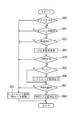
図3は、インテリジェントキーコントロールユニットが行う処理の流れを示す図である。
インテリジェントキーコントロールユニット1は、本処理をたとえば10秒毎に実行するものとする。
ステップ300においてインテリジェントキーコントロールユニット1は、ステアリングロックユニット4のメカニカルキー挿入口4Bにメカニカルキーが挿入されているかどうかを、キー挿入信号に基づいて判断する。メカニカルキーが挿入されている場合には、本処理を終了する。
なお、本処理を終了する際に、ステップ309においてATデバイス10のシフトロックの解除、およびパーキングブレーキ11のロック解除を行う。
Next, the operation of the intelligent key control unit will be described.
FIG. 3 is a diagram showing a flow of processing performed by the intelligent key control unit.
The intelligent key control unit 1 executes this process every 10 seconds, for example.
In
When this process is terminated, the shift lock of the
ステップ301においてインテリジェントキーコントロールユニット1は、エンジンコントロールユニット12から入力されるエンジン状態信号より、エンジンが作動中であるかどうかの判断を行う。エンジンが作動中でない場合にはステップ309において、ATデバイス10のシフトロック解除、およびパーキングブレーキ11のロック解除を行い、本制御を終了する。
エンジンが作動中である場合にはステップ302において、車速センサ9からの信号より車両が停止中かどうかの判断を行う。車両が停止中でない場合、すなわち車両の速度が0km/hでない場合にはステップ309へ進み、本処理を終了する。
In
If the engine is operating, it is determined in
一方、車両が停止中である場合にはステップ303においてインテリジェントキーコントロールユニット1は、室内アンテナ2を介してインテリジェントキー3にID要求信号を発信してID要求を行い、ステップ304においてインテリジェントキー3から送信されたID情報の照合を行う。
ID情報の照合結果がOKである場合にはステップ309へ進み、本処理を終了する。
ID情報の照合結果がNGである場合にはステップ305へ進む。
On the other hand, if the vehicle is stopped, the intelligent key control unit 1 sends an ID request signal to the intelligent key 3 via the
If the collation result of the ID information is OK, the process proceeds to step 309 and the process is terminated.
When the collation result of the ID information is NG, the process proceeds to step 305.
ステップ305においてインテリジェントキーコントロールユニット1は、ATデバイス10から送信されるPレンジ信号より、ATデバイス10のシフトポジションがPレンジであるかどうかの判断を行い、Pレンジでない場合にはステップ307へ進む。
一方Pレンジである場合には、ステップ306においてインテリジェントキーコントロールユニット1は、ATデバイス10に対してシフトロック信号を出力する。
これによりATデバイス10は、シフトレバー10AをPレンジ位置に固定する。
In
On the other hand, if it is in the P range, the intelligent key control unit 1 outputs a shift lock signal to the
Thereby, the
ここでATデバイス10が行う、シフトレバー10Aの固定動作について説明する。
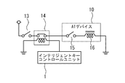
図4に、ATデバイスが行うシフトレバー10Aの固定動作を実現するための構成を示す。
車両のブレーキペダルが踏み込まれることによってオン状態となるブレーキスイッチ13が、シフトロック用リレー14を介してATデバイス10に接続される。
シフトロック用リレー14は、インテリジェントキーコントロールユニット1によってシフトロックを制御するためのものである。
ATデバイス10は内部に、パークスイッチ15とシフトロックソレノイド16とを備え、シフトロックソレノイド16の通電時にはシフトロックが解除される。
Here, the fixing operation of the
FIG. 4 shows a configuration for realizing the fixing operation of the
A
The
The
通常はインテリジェントキーコントロールユニット1からシフトロック信号が出力されていないことにより、シフトロック用リレー14はオン状態(シフトロック解除)となっている。乗員がPレンジから他のレンジにシフトレバー10Aを動かす場合は、ブレーキペダルを踏み、パークスイッチ15を押すため、シフトロックソレノイド16が通電状態となることによりシフトロックが解除され、シフトレバー10Aの操作が可能となる。
Normally, since the shift lock signal is not output from the intelligent key control unit 1, the
一方、ATデバイス10のシフトレバー10AがPレンジにある状態(パークスイッチ15はオフ状態)のときに、インテリジェントキーコントロールユニット1からシフトロック信号が出力されると、シフトロック用リレー14がオフ状態となりATデバイス10のシフトロックソレノイド16が非通電状態となるため、ATデバイス10のシフトレバー10AがPレンジに固定され、シフトロックを実現することができる。
On the other hand, when the shift lock signal is output from the intelligent key control unit 1 when the
図3に戻りステップ307においてインテリジェントキーコントロールユニット1は、パーキングブレーキ11からのパーキング信号より、パーキングブレーキ(PKB)が作動中かどうかの判断を行い、パーキングブレーキが作動していない場合には、ステップ309でシフトロックの解除を行い本処理を終了する。
一方、パーキングブレーキ11が作動中である場合には、ステップ308においてインテリジェントキーコントロールユニット1はパーキングブレーキ11に対してパーキングブレーキロック信号を出力し、本処理を終了する。
これによってパーキングブレーキ11は、パーキングブレーキが作動状態のまま固定される、パーキングブレーキロック状態となる。
Returning to FIG. 3, in
On the other hand, if the
As a result, the
以上の処理により、車両が停止中でありかつエンジンが作動中の状態で、乗員がシフトレバー10AをPレンジに設定してパーキングブレーキを引き、インテリジェントキー3を所持したまま車両から離れたとすると、ステップ306、308において出力される信号により、シフトロックおよびパーキングブレーキのロックが行われる。これにより、車両のエンジンは作動中であるが、車両を移動させることが不可能な状態となる。
With the above processing, when the vehicle is stopped and the engine is operating, the occupant sets the
また、インテリジェントキー3を携帯した乗員が車両に乗り込んだ場合には、ステップ309においてシフトロックおよびパーキングブレーキのロックが解除されて、車両を移動させることが可能となる。
なお本実施例において、インテリジェントキー3が本発明における携帯機を構成し、インテリジェントキーコントロールユニット1が本発明における車載機を構成する。また、ステップ303、304が本発明における携帯機存在判定手段を構成し、ステップ306、308が、本発明における作動禁止手段を構成する。
When the passenger carrying the intelligent key 3 gets into the vehicle, the shift lock and the parking brake are unlocked in
In this embodiment, the intelligent key 3 constitutes a portable device in the present invention, and the intelligent key control unit 1 constitutes an in-vehicle device in the present invention.
本実施例は以上のように構成され、車両が停止状態であり、かつエンジンが作動した状態で、乗員がシフトレバー10AをPレンジに設定してパーキングブレーキを引き、インテリジェントキー3を所持したまま車両から離れた場合には、インテリジェントキーコントロールユニット1からの指示によりATデバイス10がシフトロックを行い、さらにパーキングブレーキ11がパーキングブレーキを作動状態でロックする。これにより、車両のエンジンは作動状態ではあるが、シフトロックおよびパーキングブレーキのロックが行われていることにより、インテリジェントキー3を所持した乗員以外の人物によって車両を移動させることが不可能となり、車両の防盗性能が向上する。
これは、たとえば寒い地域で車両の暖房をつけたまま、乗員が売店等へ行くために短時間車両を離れた場合などに有効である。
The present embodiment is configured as described above, and the occupant sets the
This is effective, for example, when a passenger leaves the vehicle for a short time to go to a store or the like with the vehicle heated in a cold area.
なお、ATデバイス10のシフトレバー10AがPレンジでない場合には、パーキングブレーキのみがロックされ、車両の移動が不可能となる。
また、インテリジェントキー3を携帯する乗員が車両に乗り込んだ場合には、自動的にシフトロックの解除、およびパーキングブレーキのロックの解除が行われ、車両の移動が可能となる。
When the
Further, when an occupant carrying the intelligent key 3 gets into the vehicle, the shift lock and the parking brake are automatically released, and the vehicle can be moved.
さらに、車両の走行中にインテリジェントキー3の電池が切れた場合には、インテリジェントキーコントロールユニット1はステップ302において車両の車速が0km/hであるかどうかの判断を行い、0km/hである場合にのみシフトロックおよびパーキングブレーキのロックを行うので、車両の走行中にシフトロックおよびパーキングブレーキのロックが行われることがない。
なおインテリジェントキー3の電池が切れた状態で、シフトロックおよびパーキングブレーキのロックが行われてしまった場合には、メカニカルキーを用いることにより、シフトロックおよびパーキングブレーキのロックが解除され、通常走行が可能となる。
Further, if the battery of the intelligent key 3 has run out while the vehicle is running, the intelligent key control unit 1 determines whether or not the vehicle speed of the vehicle is 0 km / h in
If the shift lock and the parking brake are locked while the battery of the intelligent key 3 is dead, the shift lock and the parking brake are unlocked by using the mechanical key, and normal driving is not performed. It becomes possible.
また本実施例においては、車両の移動を不可能とさせる手段としてシフトロックやパーキングブレーキのロックを行うものとしたが、これに限定されず、たとえばステアリングのロックを行ったり、ドアのロック、アンロックを制御して、乗員がインテリジェントキー3を携帯したまま車両から離れた場合には、ドアのロックを行い、インテリジェントキー3を携帯する乗員が車両に近づいたらドアのロックを解除することもできる。 In this embodiment, the shift lock and the parking brake are locked as means for making the vehicle impossible to move. However, the present invention is not limited to this. For example, the steering is locked, the door is locked or unlocked. When the occupant leaves the vehicle while carrying the intelligent key 3 by controlling the lock, the door is locked, and when the occupant carrying the intelligent key 3 approaches the vehicle, the door can be unlocked. .
あるいは、インテリジェントキー3を携帯する乗員が車両に乗り込んだ場合に行われるシフトロックの解除、およびパーキングブレーキのロック解除は、インテリジェントキーコントロールユニット1で所定時間ごとに実行される処理のステップ309において解除されるものとしたが、車両に乗り込んだ乗員が即座に車両を移動させることを想定し、インテリジェントキーコントロールユニット1によってブレーキペダルが踏み込まれたかどうかを判断し、ブレーキペダルが踏み込まれた場合に、上記処理を行うようにしてもよい。
これにより、シフトロックおよびパーキングブレーキのロックがされた状態から、すばやくシフトロックの解除、およびパーキングブレーキのロックの解除を行い、車両を移動可能な状態とすることができる。
Alternatively, the unlocking of the shift lock and the unlocking of the parking brake performed when a passenger carrying the intelligent key 3 gets into the vehicle are canceled at
Thus, the shift lock and the parking brake can be quickly released from the state where the shift lock and the parking brake are locked, so that the vehicle can be moved.
さらに本実施例では、シフト位置がPレンジの場合にシフトロックあるいはパーキングブレーキのロックを行うものとしたが、Nレンジの場合にも、パーキングブレーキのロックを行うようにしてもよい。
これにより、ATデバイス10のシフト位置がNレンジの状態で、乗員が車両を離れた場合にもパーキングブレーキのロックが行われ、車両の防盗性能を向上させることができる。
Further, in this embodiment, the shift lock or the parking brake is locked when the shift position is in the P range. However, the parking brake may be locked also in the N range.
Accordingly, even when the shift position of the
また、車両の走行中にインテリジェントキー3の電池切れや故障によりID情報の照合が不可能となった場合において、たとえば赤信号等により車両が停車をした場合には、エンジンは作動中、および車速0km/hの条件を満たしパーキングブレーキのロックが行われることとなる。
これを防止するために、たとえば車両のドアの開閉を検出するドアセンサを備え、ドアの開閉が行われた場合にシフトロック、パーキングブレーキのロックを行うという条件を、インテリジェントキーコントロールユニット1が行う処理に付け加えることにより、乗員が車両内にいるにもかかわらず、防盗機能としてのシフトロックやパーキングブレーキのロックが行われるといったことがない。
Further, when the ID information cannot be collated due to the battery running out or malfunctioning of the intelligent key 3 while the vehicle is running, for example, when the vehicle stops due to a red signal or the like, the engine is running and the vehicle speed The parking brake is locked by satisfying the condition of 0 km / h.
In order to prevent this, for example, the intelligent key control unit 1 includes a door sensor that detects opening and closing of the vehicle door, and the intelligent key control unit 1 performs a condition that the shift lock and the parking brake are locked when the door is opened and closed. In addition, the shift lock or parking brake as an anti-theft function is not performed even though the occupant is in the vehicle.
1 インテリジェントキーコントロールユニット
2 室内アンテナ
3 インテリジェントキー
4 ステアリングロックユニット
4A イグニッションノブ
4B メカニカルキー挿入口
5 キースイッチ
6 インヒビタースイッチ
7 スタータインヒビターリレー
8 スタータモータ
9 車速センサ
10 ATデバイス
10A シフトレバー
11 パーキングブレーキ
12 エンジンコントロールユニット
13 ブレーキスイッチ
14 シフトロック用リレー
15 パークスイッチ
16 シフトロックソレノイド
DESCRIPTION OF SYMBOLS 1 Intelligent
Claims (5)
前記エンジンの始動後に、車両内に前記携帯機があるかどうかを判定する携帯機存在判定手段と、
該携帯機存在判定手段により、前記携帯機が車両内に無いと判定された場合には、前記エンジン以外の所定機器の作動を禁止する作動禁止手段とを備えたことを特徴とする防盗装置。 In the anti-theft device that performs wireless communication between the portable device and the vehicle-mounted device in the vehicle electronic key system, and can start the engine of the vehicle,
Portable device presence determining means for determining whether or not the portable device is in a vehicle after the engine is started;
An antitheft device comprising: an operation prohibiting unit that prohibits the operation of a predetermined device other than the engine when the portable device presence determining unit determines that the portable device is not in the vehicle.
前記作動禁止手段は、前記車速センサによって車両の速度0km/hが検出されている場合に、前記エンジン以外の所定機器の作動を禁止することを特徴とする請求項1記載の防盗装置。 It has a vehicle speed sensor that detects the speed of the vehicle,
2. The antitheft device according to claim 1, wherein the operation prohibiting unit prohibits the operation of a predetermined device other than the engine when a vehicle speed of 0 km / h is detected by the vehicle speed sensor.
エンジンの始動後に、車両内に前記携帯機があるかどうかを判定し、
前記携帯機が車両内に無いと判定された場合には、前記エンジン以外の所定機器の作動を禁止することを特徴とする車両用電子キー装置における防盗方法。 An anti-theft method that enables wireless communication between a portable device and an in-vehicle device in an electronic key system for a vehicle, and that can start a vehicle engine,
After starting the engine, determine whether the portable device is in the vehicle,
An anti-theft method in an electronic key device for a vehicle, wherein when it is determined that the portable device is not in the vehicle, the operation of a predetermined device other than the engine is prohibited.
Priority Applications (1)
| Application Number | Priority Date | Filing Date | Title |
|---|---|---|---|
| JP2004117733A JP2005297796A (en) | 2004-04-13 | 2004-04-13 | Anti-theft device and anti-theft method |
Applications Claiming Priority (1)
| Application Number | Priority Date | Filing Date | Title |
|---|---|---|---|
| JP2004117733A JP2005297796A (en) | 2004-04-13 | 2004-04-13 | Anti-theft device and anti-theft method |
Publications (1)
| Publication Number | Publication Date |
|---|---|
| JP2005297796A true JP2005297796A (en) | 2005-10-27 |
Family
ID=35329865
Family Applications (1)
| Application Number | Title | Priority Date | Filing Date |
|---|---|---|---|
| JP2004117733A Pending JP2005297796A (en) | 2004-04-13 | 2004-04-13 | Anti-theft device and anti-theft method |
Country Status (1)
| Country | Link |
|---|---|
| JP (1) | JP2005297796A (en) |
Cited By (8)
| Publication number | Priority date | Publication date | Assignee | Title |
|---|---|---|---|---|
| JP2007315003A (en) * | 2006-05-25 | 2007-12-06 | Toshiaki Onishi | Keyless entry system of automobile |
| KR100892473B1 (en) * | 2006-10-31 | 2009-04-10 | 현대자동차주식회사 | Automotive Smart Key Starter |
| US8281681B2 (en) | 2007-01-23 | 2012-10-09 | Toyota Jidosha Kabushiki Kaisha | Shift-by-wire system |
| WO2013179208A1 (en) * | 2012-06-01 | 2013-12-05 | Meta System S.P.A. | Battery for electric vehicles |
| JP2015000627A (en) * | 2013-06-14 | 2015-01-05 | 株式会社デンソー | Vehicle antitheft system |
| US20160304051A1 (en) * | 2015-04-20 | 2016-10-20 | Oshkosh Corporation | Response vehicle systems and methods |
| CN111959436A (en) * | 2020-08-26 | 2020-11-20 | 东风电子科技股份有限公司 | Method and device for realizing remote vehicle locking through automobile combination instrument |
| CN112277877A (en) * | 2020-10-30 | 2021-01-29 | 东风汽车集团有限公司 | A vehicle anti-theft method and storage medium based on P gear locking |
-
2004
- 2004-04-13 JP JP2004117733A patent/JP2005297796A/en active Pending
Cited By (16)
| Publication number | Priority date | Publication date | Assignee | Title |
|---|---|---|---|---|
| JP2007315003A (en) * | 2006-05-25 | 2007-12-06 | Toshiaki Onishi | Keyless entry system of automobile |
| KR100892473B1 (en) * | 2006-10-31 | 2009-04-10 | 현대자동차주식회사 | Automotive Smart Key Starter |
| US8281681B2 (en) | 2007-01-23 | 2012-10-09 | Toyota Jidosha Kabushiki Kaisha | Shift-by-wire system |
| WO2013179208A1 (en) * | 2012-06-01 | 2013-12-05 | Meta System S.P.A. | Battery for electric vehicles |
| US9358955B2 (en) | 2012-06-01 | 2016-06-07 | Meta System S.P.A. | Battery for electric vehicles |
| JP2015000627A (en) * | 2013-06-14 | 2015-01-05 | 株式会社デンソー | Vehicle antitheft system |
| US11577689B2 (en) | 2015-04-20 | 2023-02-14 | Oshkosh Corporation | Response vehicle systems and methods |
| US10144389B2 (en) * | 2015-04-20 | 2018-12-04 | Oshkosh Corporation | Response vehicle systems and methods |
| US10981538B2 (en) | 2015-04-20 | 2021-04-20 | Oshkosh Corporation | Response vehicle systems and methods |
| US20160304051A1 (en) * | 2015-04-20 | 2016-10-20 | Oshkosh Corporation | Response vehicle systems and methods |
| US12049190B2 (en) | 2015-04-20 | 2024-07-30 | Oshkosh Corporation | Response vehicle systems and methods |
| US12227144B2 (en) | 2015-04-20 | 2025-02-18 | Oshkosh Corporation | Automatic vehicle braking in response to operator egress |
| US12384328B2 (en) | 2015-04-20 | 2025-08-12 | Oshkosh Corporation | Response vehicle systems and methods |
| CN111959436A (en) * | 2020-08-26 | 2020-11-20 | 东风电子科技股份有限公司 | Method and device for realizing remote vehicle locking through automobile combination instrument |
| CN111959436B (en) * | 2020-08-26 | 2022-10-25 | 东风电子科技股份有限公司 | Method and device for realizing remote vehicle locking through automobile combination instrument |
| CN112277877A (en) * | 2020-10-30 | 2021-01-29 | 东风汽车集团有限公司 | A vehicle anti-theft method and storage medium based on P gear locking |
Similar Documents
| Publication | Publication Date | Title |
|---|---|---|
| US8543257B2 (en) | Vehicle remote operation system and on-board device | |
| EP1504972B1 (en) | Engine start Controller | |
| JP2012066689A (en) | Vehicle control system, vehicle control method, and engine control device | |
| JP2005238884A (en) | Vehicle anti-theft device | |
| JP2009143528A (en) | Shift lever locking device for vehicle | |
| JP2014129082A (en) | Vehicle remote operation system and on-vehicle machine | |
| CN103770745B (en) | Vehicle remote operation system and vehicle-mounted machine | |
| JP2010023548A (en) | Vehicular function limitation system, and key corresponding to vehicular function limitation | |
| JP2005297796A (en) | Anti-theft device and anti-theft method | |
| JP5436255B2 (en) | Remote starter | |
| JP3857383B2 (en) | Steering lock system for vehicles | |
| JP3925295B2 (en) | Electronic key device for vehicle and vehicle activation control method | |
| JP3799961B2 (en) | Electronic key device for vehicle | |
| US20080252438A1 (en) | Warning System and Method of Providing a Warning | |
| US6578655B2 (en) | Start/drive system for a vehicle | |
| JP2001018754A (en) | Electronic key device for vehicles | |
| CN100434674C (en) | Vehicle engine control system and method | |
| JP4509002B2 (en) | Remote start control device | |
| JP2007153190A (en) | Vehicle starter | |
| JP3667272B2 (en) | Smart entry system for vehicle and control method thereof | |
| JPH0515873B2 (en) | ||
| JP2011162140A (en) | Remote startup device | |
| JP3831058B2 (en) | Steering lock system for vehicles | |
| JP4910968B2 (en) | Vehicle anti-theft device | |
| JP3478144B2 (en) | Vehicle remote control device |
Legal Events
| Date | Code | Title | Description |
|---|---|---|---|
| A621 | Written request for application examination |
Free format text: JAPANESE INTERMEDIATE CODE: A621 Effective date: 20070402 |
|
| RD04 | Notification of resignation of power of attorney |
Free format text: JAPANESE INTERMEDIATE CODE: A7424 Effective date: 20080912 |
|
| A977 | Report on retrieval |
Free format text: JAPANESE INTERMEDIATE CODE: A971007 Effective date: 20090826 |
|
| A131 | Notification of reasons for refusal |
Free format text: JAPANESE INTERMEDIATE CODE: A131 Effective date: 20090929 |
|
| A02 | Decision of refusal |
Free format text: JAPANESE INTERMEDIATE CODE: A02 Effective date: 20100309 |