JP2005297765A - Storage box - Google Patents
Storage box Download PDFInfo
- Publication number
- JP2005297765A JP2005297765A JP2004116810A JP2004116810A JP2005297765A JP 2005297765 A JP2005297765 A JP 2005297765A JP 2004116810 A JP2004116810 A JP 2004116810A JP 2004116810 A JP2004116810 A JP 2004116810A JP 2005297765 A JP2005297765 A JP 2005297765A
- Authority
- JP
- Japan
- Prior art keywords
- panel
- light
- light source
- storage box
- storage
- Prior art date
- Legal status (The legal status is an assumption and is not a legal conclusion. Google has not performed a legal analysis and makes no representation as to the accuracy of the status listed.)
- Granted
Links
- 238000005286 illumination Methods 0.000 claims abstract description 21
- 239000011347 resin Substances 0.000 description 2
- 229920005989 resin Polymers 0.000 description 2
- 230000000694 effects Effects 0.000 description 1
- 239000002023 wood Substances 0.000 description 1
Images

Classifications
-
- B—PERFORMING OPERATIONS; TRANSPORTING
- B60—VEHICLES IN GENERAL
- B60Q—ARRANGEMENT OF SIGNALLING OR LIGHTING DEVICES, THE MOUNTING OR SUPPORTING THEREOF OR CIRCUITS THEREFOR, FOR VEHICLES IN GENERAL
- B60Q3/00—Arrangement of lighting devices for vehicle interiors; Lighting devices specially adapted for vehicle interiors
- B60Q3/20—Arrangement of lighting devices for vehicle interiors; Lighting devices specially adapted for vehicle interiors for lighting specific fittings of passenger or driving compartments; mounted on specific fittings of passenger or driving compartments
- B60Q3/225—Small compartments, e.g. glove compartments
-
- B—PERFORMING OPERATIONS; TRANSPORTING
- B60—VEHICLES IN GENERAL
- B60Q—ARRANGEMENT OF SIGNALLING OR LIGHTING DEVICES, THE MOUNTING OR SUPPORTING THEREOF OR CIRCUITS THEREFOR, FOR VEHICLES IN GENERAL
- B60Q3/00—Arrangement of lighting devices for vehicle interiors; Lighting devices specially adapted for vehicle interiors
- B60Q3/60—Arrangement of lighting devices for vehicle interiors; Lighting devices specially adapted for vehicle interiors characterised by optical aspects
- B60Q3/62—Arrangement of lighting devices for vehicle interiors; Lighting devices specially adapted for vehicle interiors characterised by optical aspects using light guides
- B60Q3/64—Arrangement of lighting devices for vehicle interiors; Lighting devices specially adapted for vehicle interiors characterised by optical aspects using light guides for a single lighting device
Landscapes
- Engineering & Computer Science (AREA)
- Mechanical Engineering (AREA)
- Arrangements Of Lighting Devices For Vehicle Interiors, Mounting And Supporting Thereof, Circuits Therefore (AREA)
Abstract
【課題】照明効率に秀れ且つ均一にパネル照明することができる、収納ボックスを提供する。
【解決手段】パネル部2は、半透明の導光部材であり、光源支持部3は、パネル部2の開閉に連動して、パネル閉状態では光源31a〜31cがパネル部2に設けられた受光部21a〜21cに対向し、パネル開状態では光源31a〜31cが収納部1の内壁に対向するように、パネル部2との間に介設されている。このため、パネル閉状態では、光源31a〜31cから与えられる光はパネル部2内を導光されて、これによりパネル部2全体が照明される。また、パネル開状態では同光源31a〜31cからの直接光により収納部1内部が照明される。
【選択図】図1A storage box having excellent illumination efficiency and capable of performing panel illumination uniformly is provided.
The panel unit 2 is a translucent light guide member, and the light source support unit 3 is provided with light sources 31a to 31c in the panel unit 2 when the panel is closed in conjunction with opening and closing of the panel unit 2. Opposite to the light receiving parts 21a to 21c, the light sources 31a to 31c are interposed between the panel part 2 so as to face the inner wall of the storage part 1 when the panel is open. For this reason, in the panel closed state, the light provided from the light sources 31a to 31c is guided in the panel unit 2, and thereby the entire panel unit 2 is illuminated. In the panel open state, the interior of the storage unit 1 is illuminated by direct light from the light sources 31a to 31c.
[Selection] Figure 1
Description
本発明は、車室内のインストルメントパネル等に埋設される収納ボックスに関し、特に、照明付きの収納ボックスに関する。 The present invention relates to a storage box embedded in an instrument panel or the like in a vehicle cabin, and particularly to a storage box with illumination.
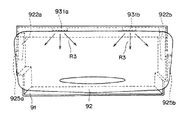
近年、車室内の前方にあるインストルメントパネル等には、照明付きの収納ボックスが埋設されることがある。図6及び図7はそれぞれ、従来のこの種の収納ボックスのパネル閉状態を示す正面図及びパネル開状態を示す平面図である。 In recent years, a storage box with illumination is sometimes embedded in an instrument panel or the like in front of a vehicle interior. 6 and 7 are a front view and a plan view, respectively, showing a panel closed state of this type of conventional storage box.
図6及び図7に示すように、従来の収納ボックスは、例えば、車室内のインストルメントパネルに埋設され、前方に開口部を有する箱状の収納部91と、収納部91の開口部に開閉自在に覆設される半透明板状のパネル部92と、から構成される。詳しくは、パネル部92は、腕部922a、922b及び腕部922a、922bに取り付けられた回転軸部925a、925bを有している。また、収納部91の内上壁には、光源931a、931bが下向きに配設されている。
As shown in FIGS. 6 and 7, the conventional storage box is embedded in, for example, an instrument panel in a passenger compartment, and has a box-
このような構成において、光源931a、931bは、例えば、ライトスイッチのオンに連動して点灯する。そして、図6に示すように、パネル部92が閉じられた状態であるパネル閉状態においては、光源931a、931bから直接光R3の木漏れ日を利用して、パネル部92が内側から照明される。また、図7に示すように、パネル部92が開かれた状態であるパネル開状態においては、光源931a、931bからの直接光R3を利用して、パネル部92の内側が照明される。
In such a configuration, the
なお、このような収納ボックスは、下記特許文献1にも開示されている。
しかしながら、上記従来の収納ボックスは、図6に示すようなパネル閉状態においては、パネル部92は、光源931a、931bからの直接光R3の木漏れ日を利用して照明されるのみである。すなわち、従来の収納ボックスでは、照明効率がよくなかった。また、同じく閉状態においては、パネル部92の裏側から与えられる光源931a、931bからの直接光R3が、パネル部92に浮き出したように見える場合があった。すなわち、従来の収納ボックスでは、照明が不均一になる傾向があった。
However, in the above-described conventional storage box, when the panel is closed as shown in FIG. 6, the
よって本発明は、上述した現状に鑑み、照明効率に秀れ且つ均一にパネル照明することができる、収納ボックスを提供することを課題としている。 Therefore, in view of the present situation described above, an object of the present invention is to provide a storage box that is excellent in illumination efficiency and can perform panel illumination uniformly.
上記課題を解決するためになされた請求項1記載の収納ボックスは、前方に開口部を有する箱状の収納部と、前記開口部に開閉自在に覆設されるパネル部と、前記収容部及び前記パネル部に照明光を与えるための光源を支持する光源支持部と、を含み、前記パネル部は、半透明の導光部材であり、前記光源支持部は、前記パネル部の開閉に連動して、前記パネル部の閉状態では前記光源が前記パネル部に設けられた受光部に対向し、前記パネル部の開状態では前記光源が前記収納部の内壁に対向するように、前記パネル部との間に介設されている、ことを特徴とする。
The storage box according to
請求項1記載の発明によれば、パネル部は、半透明の導光部材であり、光源支持部は、パネル部の開閉に連動して、パネル閉状態では光源がパネル部に設けられた受光部に対向し、パネル開状態では光源が収納部の内壁に対向するように、パネル部との間に介設されている。このため、パネル閉状態では、光源から与えられる光はパネル部内を導光されて、これによりパネル部全体が照明される。また、パネル開状態では同光源からの直接光により収納部内部が照明される。 According to the first aspect of the invention, the panel portion is a translucent light guide member, and the light source support portion is interlocked with the opening and closing of the panel portion, and the light source is provided in the panel portion when the panel is closed. The light source is interposed between the panel unit and the panel so that the light source faces the inner wall of the storage unit when the panel is open. For this reason, in the panel closed state, the light provided from the light source is guided through the panel unit, and thereby the entire panel unit is illuminated. Further, when the panel is open, the interior of the storage unit is illuminated by direct light from the light source.
上記課題を解決するためになされた請求項2記載の収納ボックスは、請求項1記載の収納ボックスにおいて、前記受光部は、前記パネル部の上端部に複数突設され、前記光源は、前記閉状態において前記受光部に対応するように、前記光源支持部に複数配設されている、ことを特徴とする。
The storage box according to
請求項2記載の発明によれば、受光部は、パネル部の上端部に複数突設され、光源は、閉状態において受光部に対応するように、光源支持部に複数配設されているので、照明効率が高くなるうえにパネル照明が均一になる。 According to the second aspect of the present invention, a plurality of light receiving portions are provided on the upper end portion of the panel portion, and a plurality of light sources are disposed on the light source support portion so as to correspond to the light receiving portions in the closed state. In addition to high lighting efficiency, the panel lighting becomes uniform.
上記課題を解決するためになされた請求項3記載の収納ボックスは、請求項2記載の収納ボックスにおいて、前記光源支持部は、前記収納部に軸支されると共に、前記開閉をガイドするためのガイドピン、を含み、前記収納部は、前記ガイドピンを、前記開閉にしたがって前記パネル部を前記閉状態及び前記開状態の間でスライドさせるガイドスリット、を含む、ことを特徴とする。
The storage box according to
請求項3記載の発明によれば、光源支持部は、収納部に軸支されると共に、開閉をガイドするためのガイドピンを含み、収納部は、ガイドピンを開閉にしたがってパネル部を閉状態及び開状態の間でスライドさせるガイドスリットを含んでいるので、パネル部の開閉が円滑になる。 According to the third aspect of the present invention, the light source support portion is pivotally supported by the storage portion and includes a guide pin for guiding opening and closing, and the storage portion is in a state in which the panel portion is closed according to opening and closing of the guide pin. Since the guide slit is slid between the open state and the open state, the panel portion can be opened and closed smoothly.
上記課題を解決するためになされた請求項4記載の収納ボックスは、請求項1〜3のいずれか一項に記載の収納ボックスにおいて、車室内のインストルメントパネルに埋設される、ことを特徴とする。
The storage box according to claim 4, which is made to solve the above problem, is embedded in an instrument panel in a vehicle compartment in the storage box according to any one of
請求項4記載の発明によれば、車室内のインストルメントパネルに埋設されるので、効率的に、収納ボックス内部や車室前方が照明される。 According to invention of Claim 4, since it embed | buries in the instrument panel of a vehicle interior, the inside of a storage box and the vehicle interior front are illuminated efficiently.
請求項1記載の発明によれば、パネル部は、半透明の導光部材であり、光源支持部は、パネル部の開閉に連動して、パネル閉状態では光源がパネル部に設けられた受光部に対向し、パネル開状態では光源が収納部の内壁に対向するように、パネル部との間に介設されている。このため、パネル閉状態では、光源から与えられる光はパネル部内を導光されて、これによりパネル部全体が照明される。また、パネル開状態では同光源からの直接光により収納部内部が照明される。したがって、照明効率に秀れ且つ均一なパネル照明が提供される。 According to the first aspect of the invention, the panel portion is a translucent light guide member, and the light source support portion is interlocked with the opening and closing of the panel portion, and the light source is provided in the panel portion when the panel is closed. The light source is interposed between the panel unit and the panel so that the light source faces the inner wall of the storage unit when the panel is open. For this reason, in the panel closed state, the light provided from the light source is guided through the panel unit, and thereby the entire panel unit is illuminated. Further, when the panel is open, the interior of the storage unit is illuminated by direct light from the light source. Therefore, uniform panel illumination with excellent illumination efficiency is provided.
請求項2記載の発明によれば、受光部は、パネル部の上端部に複数突設され、光源は、閉状態において受光部に対応するように、光源支持部に複数配設されている。したがって、より照明効率に秀れ且つ均一なパネル照明が提供される。 According to the second aspect of the present invention, a plurality of light receiving portions project from the upper end portion of the panel portion, and a plurality of light sources are disposed on the light source support portion so as to correspond to the light receiving portions in the closed state. Accordingly, a panel illumination that is more excellent in illumination efficiency and uniform is provided.
請求項3記載の発明によれば、光源支持部は、収納部に軸支されると共に、開閉をガイドするためのガイドピンを含み、収納部は、ガイドピンを開閉にしたがってパネル部を閉状態及び開状態の間でスライドさせるガイドスリットを含んでいる。したがって、パネル部の開閉を安定的に円滑に行うことができる。
According to the invention described in
請求項4記載の発明によれば、車室内のインストルメントパネルに埋設されるので、効率的に、収納ボックス内部や車室前方が照明される。また、高級感のあるイルミネーションとしても利用可能になる。 According to invention of Claim 4, since it embed | buries in the instrument panel of a vehicle interior, the inside of a storage box and the vehicle interior front are illuminated efficiently. It can also be used as a luxury illumination.
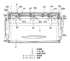
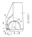
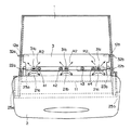
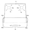
以下、本発明の実施の形態を図面に基づいて説明する。図1及び図2はそれぞれ、本発明の一実施形態の収納ボックスのパネル閉状態を示す正面図及び側面図である。図3及び図4はそれぞれ、本発明の一実施形態の収納ボックスのパネル開状態を示す正面図及び側面図である。 Hereinafter, embodiments of the present invention will be described with reference to the drawings. 1 and 2 are a front view and a side view, respectively, showing a panel closed state of a storage box according to an embodiment of the present invention. 3 and 4 are a front view and a side view, respectively, showing a panel open state of the storage box according to the embodiment of the present invention.
図1〜図4に示すように、この収納ボックスは、例えば、車室内のインストルメントパネルに埋設され、前方に開口部を有する箱状の収納部1と、収納部1の開口部に開閉自在に覆設されるパネル部2と、収容部1及びパネル部2に照明光を与えるための光源31a〜31cを支持する光源支持部3と、を含んで構成される。
As shown in FIGS. 1 to 4, for example, the storage box is embedded in an instrument panel in a passenger compartment, and can be opened and closed to a box-
収納部1は、黒系色の樹脂製であり、上壁を構成する壁板11、両内壁面にそれぞれ設けられたガイドスリット12a、12bを有している。ガイドスリット12a、12bは、後述のガイドピン32a、32bを、パネル開閉にしたがってパネル部2を閉状態及び開状態の間でスライドさせるように、円弧状にくりぬかれて形成されている。壁板11には、光源31a〜31cに対応する孔11a〜11cが穿設されている(孔11a、11bは不図示)。
The
パネル部2の主要部分は、半透明の樹脂製の導光板で構成されている。パネル部2は、正面からみると、収納部1の開口部と略同形状かやや大きめに形成されている。パネル部2の上端部には、等間隔で台形状の複数の受光部21a〜21cが突設されている。パネル部2の主要部分には、上腕部22a、22b、後片部26a、26bが連結されている。上腕部22a、22bには回転軸23a、23bが突設され、後片部26a、26bにはガイドピン24a、24b、回転軸25a、25bが突設されている。なお、ガイドピン24a、回転軸25aは、ここでは、ガイドピン24b、回転軸25bと対になるものであるが、ここでは、図示していない。
The main part of the
光源支持部3は、黒系色の所定厚の板状の樹脂製であり、複数の光源31a〜31cが配設されている。詳しくは、複数の光源31a、31b、31cはそれぞれ、パネル閉状態において、受光部21a、21b、21cに対向するように、光源支持部3上に配設されている。光源31a〜31cは、例えば、周知のLEDが用いられる。光源支持部3には、上記回転軸23a、23bが挿通されると共に、他端には、上記ガイドスリット12a、12bにガイドされるガイドピン32a、32bが突設されている。なお、n1〜n4は、光源31a〜31cに関する部材等を固定するネジである。
The light
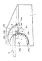
このような構成の収納ボックスの作用を図5を加えて説明する。図5は、パネル部の開閉動作を説明するための側面図である。なお、図5は、図4に対応する側面図である。 The operation of the storage box having such a configuration will be described with reference to FIG. FIG. 5 is a side view for explaining the opening and closing operation of the panel unit. FIG. 5 is a side view corresponding to FIG.
まず、光源31a〜31cは、例えば、ライトスイッチのオンに連動して点灯する。図1、図2に示すように、パネル部2が閉じられた状態であるパネル閉状態においては、光源支持部3のガイドピン32a、32bは、ガイドスリット12a、12bの上端部に維持され、これにより光源31a〜31cは下を向いて、受光部21a〜21cに対向する。そして、光源31a〜31cからの光はそれぞれ、受光部21a〜21cにて受光された後、点線矢印R1で示すように、導光板でもあるパネル部2内を進行する。
First, the
このように、パネル閉状態においては、光源31a〜31cからの光はそれぞれ、受光部21a〜21cにて受光された後、パネル部2内を進行していくため、パネル部2全体が均等に照明される。光源31a〜31cからの光はそれぞれ、突設された受光部21a〜21cにて受光されるので、光が無駄になることがない。すなわち、非常に照明効率が高くなる。
In this way, in the panel closed state, the light from the
この状態から、パネル部2が開かれる場合には、図5に示すように、パネル部2は回転軸25a、25bを中心にして回転していき、図3、図4に示すような状態に向かう。パネル部2の回転にともない、光源支持部3のガイドピン32a、32bは、図5に示すように、ガイドスリット12a、12bに沿ってスライドしていく。なお、これにともないガイドピン24a、24bもまた、ガイドスリット14a、14bに沿ってスライドする。
When the
このように、パネル部2の回転動作にしたがい、光源支持部3のガイドピン32a、32bは、図5に示すように、ガイドスリット12a、12bに沿ってスライドしていく。したがって、パネル部2の開閉を安定的に円滑に行うことができる。
As described above, according to the rotation operation of the
図3、図4に示すように、パネル部2が開かれた状態であるパネル開状態においては、光源支持部3のガイドピン32a、32bは、ガイドスリット12a、12bの下端部に維持される。このとき、光源31a〜31cは、図1、図2に示すパネル閉状態よりも、下方に移動しているが、依然として下を向いている。特に、光源31a〜31cは、壁板11の孔11a〜11cを介して、収納部1の下内壁に対向する。そして、光源31a〜31cからの直接光R2はそれぞれ、収納部1内部を側方、下方に進行して、収納部1内部を照明する。
As shown in FIGS. 3 and 4, the guide pins 32a and 32b of the light
このように、パネル開状態においては、光源31a〜31cは、収納部1の下内壁に近づき、下内壁に対向しているので、収納部1内部を非常に明るく照明することができる。すなわち、パネル開状態においても、非常に照明効率が高くなる。
Thus, in the panel open state, since the
なお、上例とは逆に、パネル開状態からパネル閉状態に変位するときには、ガイドピンがガイドスリットを逆方向に移動するのみであり、基本的な作用は上例と同様である。 Contrary to the above example, when the panel is displaced from the panel open state to the panel closed state, the guide pin only moves in the reverse direction of the guide slit, and the basic action is the same as in the above example.
以上のように、本発明の実施形態によれば、照明効率に秀れ且つ均一にパネル照明することができる、収納ボックスを提供することができる。また、共通光源をパネル開閉時に兼用しているので、部品点数削減効果もある。 As described above, according to the embodiment of the present invention, it is possible to provide a storage box that is excellent in illumination efficiency and can perform panel illumination uniformly. In addition, since the common light source is also used for opening and closing the panel, there is an effect of reducing the number of parts.
なお、本発明の収納ボックスは、車両のみならず、室内にも適用可能である。例えば、寝室内の常備灯を兼ねた収納ボックスとしても利用可能である。但し、車室内のインストルメントパネルに埋設することにより、効率的に収納ボックス内部や車室前方を照明できるようになるうえに、高級感のあるイルミネーションとしても利用可能になる。 Note that the storage box of the present invention can be applied not only to a vehicle but also to a room. For example, it can be used as a storage box that also serves as a standing lamp in the bedroom. However, by embedding it in the instrument panel in the passenger compartment, the interior of the storage box and the front of the passenger compartment can be efficiently illuminated, and it can be used as a high-quality illumination.
また、本発明の収納ボックスのパネル部には、例えば、半透明の木目調の化粧板等を装着するようにしてもよい。これにより、より高級感のあるイルミネーションとしての利用が可能になる。また、光源を適宜減光可能にしてもよい。これにより、更に高級感のあるイルミネーションとしての利用が可能になる。また、本発明の収納ボックスの収納部は、例示した形状のみならず、例えば、円筒状箱型であってもよい。本発明は、その主旨の範囲内で変更されたものも含むものである。 Moreover, you may make it equip the panel part of the storage box of this invention with a translucent wood grain decorative board etc., for example. As a result, it can be used as a more luxurious illumination. Further, the light source may be appropriately dimmable. As a result, it can be used as a more luxurious illumination. Further, the storage portion of the storage box of the present invention is not limited to the illustrated shape, and may be, for example, a cylindrical box shape. The present invention includes those modified within the scope of the gist thereof.
1 収納部
2 パネル部
3 光源支持部
31a〜31c 光源
21a〜21c 受光部
DESCRIPTION OF
Claims (4)
前記開口部に開閉自在に覆設されるパネル部と、
前記収容部及び前記パネル部に照明光を与えるための光源を支持する光源支持部と、
を含み、
前記パネル部は、
半透明の導光部材であり、
前記光源支持部は、
前記パネル部の開閉に連動して、
前記パネル部の閉状態では前記光源が前記パネル部に設けられた受光部に対向し、
前記パネル部の開状態では前記光源が前記収納部の内壁に対向するように、
前記パネル部との間に介設されている、
ことを特徴とする収納ボックス。 A box-shaped storage unit having an opening in the front;
A panel portion that is openably and closably covered in the opening;
A light source support that supports a light source for providing illumination light to the housing and the panel; and
Including
The panel portion is
A translucent light guide member,
The light source support is
In conjunction with opening and closing of the panel part,
In the closed state of the panel part, the light source faces a light receiving part provided in the panel part,
In the open state of the panel part, the light source faces the inner wall of the storage part,
Interposed between the panel portion,
A storage box characterized by that.
前記受光部は、
前記パネル部の上端部に複数突設され、
前記光源は、
前記閉状態において前記受光部に対応するように、前記光源支持部に複数配設されている、
ことを特徴とする収納ボックス。 The storage box according to claim 1.
The light receiving unit is
A plurality of protrusions are provided at the upper end of the panel portion,
The light source is
A plurality of light source support portions are disposed so as to correspond to the light receiving portions in the closed state.
A storage box characterized by that.
前記光源支持部は、
前記収納部に軸支されると共に、前記開閉をガイドするためのガイドピン、を含み、
前記収納部は、
前記ガイドピンを、前記開閉にしたがって前記パネル部を前記閉状態及び前記開状態の間でスライドさせるガイドスリット、を含む、
ことを特徴とする収納ボックス。 The storage box according to claim 2,
The light source support is
A guide pin that is pivotally supported by the storage portion and guides the opening and closing;
The storage section is
A guide slit that slides the panel portion between the closed state and the open state according to the opening and closing of the guide pin,
A storage box characterized by that.
車室内のインストルメントパネルに埋設される、
ことを特徴とする収納ボックス。 In the storage box as described in any one of Claims 1-3,
Embedded in the instrument panel in the passenger compartment,
A storage box characterized by that.
Priority Applications (1)
| Application Number | Priority Date | Filing Date | Title |
|---|---|---|---|
| JP2004116810A JP4243212B2 (en) | 2004-04-12 | 2004-04-12 | Storage box and instrument panel in which it is embedded |
Applications Claiming Priority (1)
| Application Number | Priority Date | Filing Date | Title |
|---|---|---|---|
| JP2004116810A JP4243212B2 (en) | 2004-04-12 | 2004-04-12 | Storage box and instrument panel in which it is embedded |
Publications (2)
| Publication Number | Publication Date |
|---|---|
| JP2005297765A true JP2005297765A (en) | 2005-10-27 |
| JP4243212B2 JP4243212B2 (en) | 2009-03-25 |
Family
ID=35329836
Family Applications (1)
| Application Number | Title | Priority Date | Filing Date |
|---|---|---|---|
| JP2004116810A Expired - Fee Related JP4243212B2 (en) | 2004-04-12 | 2004-04-12 | Storage box and instrument panel in which it is embedded |
Country Status (1)
| Country | Link |
|---|---|
| JP (1) | JP4243212B2 (en) |
Cited By (4)
| Publication number | Priority date | Publication date | Assignee | Title |
|---|---|---|---|---|
| DE102008001462A1 (en) | 2007-06-21 | 2008-12-24 | Suzuki Motor Corp., Hamamatsu | dashboard |
| CN101879905A (en) * | 2010-07-13 | 2010-11-10 | 三一重型装备有限公司 | Instrument console for underground engineering vehicle cab |
| JP2011102088A (en) * | 2009-11-11 | 2011-05-26 | Toyoda Gosei Co Ltd | Vehicular console lamp |
| CN107696966A (en) * | 2016-08-09 | 2018-02-16 | 福特全球技术公司 | Light emitting control platform storage box |
-
2004
- 2004-04-12 JP JP2004116810A patent/JP4243212B2/en not_active Expired - Fee Related
Cited By (6)
| Publication number | Priority date | Publication date | Assignee | Title |
|---|---|---|---|---|
| DE102008001462A1 (en) | 2007-06-21 | 2008-12-24 | Suzuki Motor Corp., Hamamatsu | dashboard |
| US7597377B2 (en) | 2007-06-21 | 2009-10-06 | Suzuki Motor Corporation | Instrument panel |
| DE102008001462B4 (en) * | 2007-06-21 | 2012-12-27 | Suzuki Motor Corp. | dashboard |
| JP2011102088A (en) * | 2009-11-11 | 2011-05-26 | Toyoda Gosei Co Ltd | Vehicular console lamp |
| CN101879905A (en) * | 2010-07-13 | 2010-11-10 | 三一重型装备有限公司 | Instrument console for underground engineering vehicle cab |
| CN107696966A (en) * | 2016-08-09 | 2018-02-16 | 福特全球技术公司 | Light emitting control platform storage box |
Also Published As
| Publication number | Publication date |
|---|---|
| JP4243212B2 (en) | 2009-03-25 |
Similar Documents
| Publication | Publication Date | Title |
|---|---|---|
| CN105026211B (en) | Slim overhead console | |
| JP2011068356A (en) | Lamp assembly having variable focus and directionality | |
| CN101725883B (en) | Vehicle headlight | |
| JP2008174132A (en) | Vehicle interior lighting device | |
| JP4669552B2 (en) | Lighting structure | |
| KR101810890B1 (en) | Edge Type LED Lighting Device | |
| JP4243212B2 (en) | Storage box and instrument panel in which it is embedded | |
| JP5287188B2 (en) | Storage | |
| JP2007157448A (en) | Lighting device for mirror cabinet | |
| JP2012002628A (en) | Pointer and light guiding member | |
| JP2010146973A (en) | Lighting fixture | |
| KR101974893B1 (en) | Storage device for a vehicle comprising an illuminated facade | |
| JP4426952B2 (en) | Illuminated slide switch device | |
| WO2011118769A1 (en) | Lighting unit with switch | |
| JP2007305488A (en) | Operation switch device | |
| KR101983722B1 (en) | door trim light guide prefabricatd structure for vehicle room lighting | |
| JP2009259649A (en) | Luminaire | |
| JP5450035B2 (en) | Vehicle lighting device | |
| JP6569984B2 (en) | Switch handle and switch | |
| JP2012146457A (en) | Illumination structure of dial type operation knob | |
| JP2007280780A (en) | Push type switch | |
| KR200396842Y1 (en) | Fixing Instrument of Cover for Ceiling Light | |
| JP2017144878A (en) | Lens member of vehicle lamp fitting, vehicle lamp fitting | |
| WO2016158355A1 (en) | Vehicular interior member with illumination device | |
| KR102573851B1 (en) | Led lighting mirrors |
Legal Events
| Date | Code | Title | Description |
|---|---|---|---|
| A621 | Written request for application examination |
Free format text: JAPANESE INTERMEDIATE CODE: A621 Effective date: 20060904 |
|
| A977 | Report on retrieval |
Free format text: JAPANESE INTERMEDIATE CODE: A971007 Effective date: 20081001 |
|
| A131 | Notification of reasons for refusal |
Free format text: JAPANESE INTERMEDIATE CODE: A131 Effective date: 20081007 |
|
| A521 | Request for written amendment filed |
Free format text: JAPANESE INTERMEDIATE CODE: A523 Effective date: 20081121 |
|
| TRDD | Decision of grant or rejection written | ||
| A01 | Written decision to grant a patent or to grant a registration (utility model) |
Free format text: JAPANESE INTERMEDIATE CODE: A01 Effective date: 20081216 |
|
| A01 | Written decision to grant a patent or to grant a registration (utility model) |
Free format text: JAPANESE INTERMEDIATE CODE: A01 |
|
| A61 | First payment of annual fees (during grant procedure) |
Free format text: JAPANESE INTERMEDIATE CODE: A61 Effective date: 20081226 |
|
| FPAY | Renewal fee payment (event date is renewal date of database) |
Free format text: PAYMENT UNTIL: 20120109 Year of fee payment: 3 |
|
| R150 | Certificate of patent or registration of utility model |
Ref document number: 4243212 Country of ref document: JP Free format text: JAPANESE INTERMEDIATE CODE: R150 Free format text: JAPANESE INTERMEDIATE CODE: R150 |
|
| FPAY | Renewal fee payment (event date is renewal date of database) |
Free format text: PAYMENT UNTIL: 20120109 Year of fee payment: 3 |
|
| FPAY | Renewal fee payment (event date is renewal date of database) |
Free format text: PAYMENT UNTIL: 20130109 Year of fee payment: 4 |
|
| FPAY | Renewal fee payment (event date is renewal date of database) |
Free format text: PAYMENT UNTIL: 20140109 Year of fee payment: 5 |
|
| R250 | Receipt of annual fees |
Free format text: JAPANESE INTERMEDIATE CODE: R250 |
|
| R250 | Receipt of annual fees |
Free format text: JAPANESE INTERMEDIATE CODE: R250 |
|
| R250 | Receipt of annual fees |
Free format text: JAPANESE INTERMEDIATE CODE: R250 |
|
| R250 | Receipt of annual fees |
Free format text: JAPANESE INTERMEDIATE CODE: R250 |
|
| R250 | Receipt of annual fees |
Free format text: JAPANESE INTERMEDIATE CODE: R250 |
|
| LAPS | Cancellation because of no payment of annual fees |