JP2010146973A - Lighting fixture - Google Patents
Lighting fixture Download PDFInfo
- Publication number
- JP2010146973A JP2010146973A JP2008326008A JP2008326008A JP2010146973A JP 2010146973 A JP2010146973 A JP 2010146973A JP 2008326008 A JP2008326008 A JP 2008326008A JP 2008326008 A JP2008326008 A JP 2008326008A JP 2010146973 A JP2010146973 A JP 2010146973A
- Authority
- JP
- Japan
- Prior art keywords
- light
- lighting fixture
- opening surface
- light source
- reflecting
- Prior art date
- Legal status (The legal status is an assumption and is not a legal conclusion. Google has not performed a legal analysis and makes no representation as to the accuracy of the status listed.)
- Pending
Links
Images
Landscapes
- Non-Portable Lighting Devices Or Systems Thereof (AREA)
Abstract
【課題】薄型でかつ多機能の配光を実現することのできる照明器具を提供する。
【解決手段】本発明の照明器具は、開口面102を有する筐体100と、前記開口面から発光可能に形成された面状の光源と、前記開口面の少なくとも一つの縁に取付けられ、前記開口面に対して回動自在に取付けられた反射部とを具備している。従って、一般拡散光が必要なときは、反射部を押し上げ開口面を露呈させることで、配光でき、集光が必要なときは、反射板を本体に対して傾斜させ手配することで、自由な集光と照度を得ることができる。
【選択図】図1A lighting apparatus capable of realizing a thin and multifunctional light distribution is provided.
A lighting apparatus according to the present invention is attached to a casing 100 having an opening surface 102, a planar light source formed to emit light from the opening surface, and at least one edge of the opening surface. And a reflecting portion that is pivotably attached to the opening surface. Therefore, when general diffused light is required, light can be distributed by pushing up the reflecting part to expose the opening surface. When condensing is necessary, the reflector can be tilted with respect to the main body and arranged freely. Light concentration and illuminance can be obtained.
[Selection] Figure 1
Description
本発明は、照明器具に係り、特に配光状態を変更可能な照明器具に関する。 The present invention relates to a lighting fixture, and more particularly to a lighting fixture capable of changing a light distribution state.
光量や、光の方向を変化させることのできる可変光源装置としては、種々の装置が提案されている。
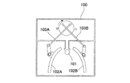
例えば、図9に示すように、筐体100内に棒状の光源ランプとしての面状光源101を配置し、開状態において反射機能を有するシャッタ102A、102Bを開閉自在に装着した光源装置が提案されている。このシャッタ102A、102Bは支持部103A、103Bによって開閉自在となるように形成されている(特許文献1)。
この光源装置は露光用光源として、用いられ、高精度の位置精度で使用することができる。
Various devices have been proposed as variable light source devices that can change the amount of light and the direction of light.
For example, as shown in FIG. 9, a light source device is proposed in which a
This light source device is used as a light source for exposure, and can be used with high positional accuracy.
しかしながら、近年、住宅のリビングダイニングにおいては、その使われ方が多様化しており、照明器具においても、複数人が種々の異なる使い方をすることも珍しくはない。 However, in recent years, the usage of living living dining in homes has been diversified, and it is not uncommon for a plurality of people to use the lighting fixtures in various different ways.
このように、複数人が種々の異なる使い方をする場合が多々あることから、種々の配光を実現することのできる多機能型の照明器具が求められている。しかしながら、多機能照明を実現することのできるコンパクトタイプで機能性の高い照明器具はこれまでになかった。
本発明は、前記実情に鑑みてなされたもので、薄型でかつ多機能の配光を実現することのできる照明器具を提供することを目的とする。
Thus, since there are many cases where a plurality of people use in various different ways, a multifunctional lighting apparatus capable of realizing various light distributions is required. However, there has never been a compact and highly functional lighting fixture capable of realizing multi-function lighting.
This invention is made | formed in view of the said situation, and it aims at providing the lighting fixture which can implement | achieve thin and multifunctional light distribution.
そこで本発明の照明器具は、開口面を有する筐体と、前記開口面から発光可能に形成された面状の光源と、前記開口面の少なくとも一つの縁に取付けられ、前記開口面に対して回動自在に取付けられた反射部とを具備したことを特徴とする。
この構成により、一般拡散光が必要なときは、反射部を押し上げ開口面を露呈させることで、配光でき、集光が必要なときは、反射板を本体に対して傾斜させ手配することで、自由な集光と照度を得ることができる。
Therefore, the lighting fixture of the present invention is attached to at least one edge of the housing having an opening surface, a planar light source formed to emit light from the opening surface, and with respect to the opening surface. And a reflecting portion attached rotatably.
With this configuration, when general diffused light is required, light can be distributed by pushing up the reflecting part to expose the opening surface, and when condensing is necessary, the reflector can be arranged with an inclination relative to the main body. , Free light collection and illuminance can be obtained.
また本発明は、上記照明器具において、前記縁を軸として回動する支持部を具備し、前記反射部は、前記支持部の当該縁と反対側の端部に取り付けられたものを含む。
この構成により、支持部の両端で筐体(の縁)と、反射部とがそれぞれ回動可能となるように形成することができ、反射部の位置および方向の設定における自由度を高めることができる。
Moreover, this invention comprises the support part rotated about the said edge in the said lighting fixture, The said reflection part contains what was attached to the edge part on the opposite side to the said edge of the said support part.
With this configuration, it is possible to form the casing (the edge) and the reflecting portion so as to be rotatable at both ends of the supporting portion, respectively, and increase the degree of freedom in setting the position and direction of the reflecting portion. it can.
また本発明は、上記照明器具において、前記光源は、開口面と略同じ形状の発光面を有する面状光源であり、前記反射部は、前記筐体の任意の対称軸を挟んで、対向するように配置されるものを含む。
この構成により、筐体の直下を中心とする領域に、種々の配光を実現することができる。
Moreover, the present invention is the above-described lighting apparatus, wherein the light source is a planar light source having a light emitting surface having substantially the same shape as the opening surface, and the reflecting portion is opposed across an arbitrary axis of symmetry of the housing. Including those arranged in such a way.
With this configuration, various light distributions can be realized in a region centered directly below the housing.
また本発明は、上記照明器具において、前記光源は、有機エレクトロルミネッセンス素子であるものを含む。 Moreover, this invention contains what the said light source is an organic electroluminescent element in the said lighting fixture.
また本発明は、上記照明器具において、前記反射部は、一方の面のみが反射面で構成された反射板であるものを含む。
この構成によれば、反射部を収納したとき、所望の表面を形成することができ、反射部を開いたときは所望の反射面を形成することが可能となる。
Moreover, the present invention includes the above-described lighting device, wherein the reflecting portion is a reflecting plate having only one surface formed by a reflecting surface.
According to this configuration, a desired surface can be formed when the reflecting portion is housed, and a desired reflecting surface can be formed when the reflecting portion is opened.
また本発明は、上記照明器具において、前記反射部は、両面が反射面で構成された反射板であるものを含む。
この構成によれば、正面方向への集中光と同時に器具背面側への反射光を得ることができ、部屋が広く見える雰囲気のある空間を作ることが可能となる。
Moreover, this invention includes the said lighting fixture whose said reflection part is a reflecting plate with which both surfaces were comprised by the reflective surface.
According to this configuration, it is possible to obtain reflected light to the back side of the instrument simultaneously with the concentrated light in the front direction, and it is possible to create a space with an atmosphere in which the room can be seen widely.
以上のように、本発明によれば、極めて簡単な構成で、薄型かつ多機能の配光が可能な照明器具を提供することが可能となる。 As described above, according to the present invention, it is possible to provide a lighting fixture capable of thin and multifunctional light distribution with a very simple configuration.
以下、本発明の実施の形態に係る照明器具について、図面を参照しつつ詳細に説明する。 Hereinafter, a lighting apparatus according to an embodiment of the present invention will be described in detail with reference to the drawings.
(実施の形態1)
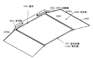
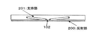
図1乃至5は本発明の実施の形態に係る照明器具を示す説明図である。図1は、この照明器具を展開した状態を示す斜視図、図2は図1の側面図、図3は、同照明器具の反射部を回動した状態を示す図、図4は、同照明器具の反射部を更に別の状態に回動した状態を示す図、図5は、同照明器具の反射部を収納し完全に閉じた状態を示す図である。
本発明の照明器具は、面状光源101として有機LED素子が、開口面102全面に形成された筐体100と、前記開口面102の少なくとも一つの縁に取付けられ、前記開口面102に対して回動自在に取付けられた反射部200とを具備したことを特徴とする。
ここで反射部200(200a、200b)は、筐体100の中心を対称軸として、対向するように2個配置されている。
(Embodiment 1)
1 to 5 are explanatory views showing a lighting apparatus according to an embodiment of the present invention. FIG. 1 is a perspective view showing a state in which the lighting fixture is deployed, FIG. 2 is a side view of FIG. 1, FIG. 3 is a view showing a state in which a reflecting portion of the lighting fixture is rotated, and FIG. The figure which shows the state which rotated the reflection part of the fixture to another state, FIG. 5 is a figure which shows the state which accommodated the reflection part of the lighting fixture, and was closed completely.
In the lighting fixture of the present invention, an organic LED element as the
Here, two reflecting portions 200 (200a, 200b) are arranged so as to face each other with the center of the
ここで器具本体としての筐体100は薄型の箱型を有しており、天井に取り付けられ仮面には枠部を持つ開口面102を有している。そしてこの開口面102が有機LED素子からなる面状光源101を構成する。そして、反射部200は、それぞれ支持部201によって支持せしめられている。この支持部201は、筐体100の端縁に取り付けられた第1の回動軸202と、反射部200の端縁に第2の回動軸203を介して取り付けられており、筐体100の開口面に対する反射部の角度を調整可能に形成されている。
Here, the
この第1および第2の回動軸202、203は筐体100を貫通して筐体の側面に支持部(図示せず)を具備している。回動軸には、適度な制動機構が内蔵されており、回動範囲内であれば、任意の角度で保持することが可能である。よって光の反射方向を制御することができるので作業面の位置が変化しても対応可能である。
そして更に、支持部201は各反射部200(200a、200b)に対してそれぞれ、相対向する位置に2個づつ設けられ、反射部を安定に支持している。ここでは奥に位置するため、図示を省略する。
The first and second rotating shafts 202 and 203 pass through the
Further, two support portions 201 are provided at positions facing each other with respect to each reflection portion 200 (200a, 200b), and stably support the reflection portions. Here, since it is located in the back, illustration is abbreviate | omitted.
なお、この面状光源101は、開口面102と略同じ形状の発光面を有しており、反射部200は、内側面が反射面204を構成すると共に外側面も反射面205を構成している。
また、支持部201は、両端に第1および第2の回動軸202と203とを挿通する穴を有している。そして、反射部200は2部品からなり、完全に開いた状態では、筐体の開口面102とほぼ同一となるように構成され、1部品が筐体の下面の半分となっている。さらにまた、反射部200の側面には支持部201の一端にある第2の回動軸203が挿通される挿通穴が形成されている。
そしてこの挿通穴は図3に示すように、反射部200を並べた時に当接する側面に設けられ、筐体の側面と近接する位置に設けられる。
The
Further, the support portion 201 has holes through which the first and second rotating shafts 202 and 203 are inserted at both ends. The reflecting portion 200 is composed of two parts, and is configured to be substantially the same as the
As shown in FIG. 3, the insertion hole is provided on a side surface that comes into contact when the reflecting portions 200 are arranged, and is provided at a position close to the side surface of the housing.
次に、この照明器具の使用形態について説明する。
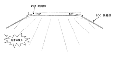
まず、室内全体にわたった光を供給する場合は、図1および2に示すように、反射部200を筐体100の開口面102に対して30度程度傾けた状態に固定する。このとき自然な有機EL照明が実現され、比較的やわらかい光を供給することができる。このように反射部200を筐体本体100に対して傾斜させて隣接させることで、自由な集光と照度を得ることができる。
Next, the usage pattern of this lighting fixture will be described.
First, when supplying light over the entire room, as shown in FIGS. 1 and 2, the reflecting portion 200 is fixed in a state inclined about 30 degrees with respect to the
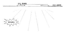
次いで、一般拡散光が欲しい時は、図3に示すように、反射部200を広げ押し上げることで、完全に開いた状態となる。この場合は、反射部が突出していない状態となるので外観がすっきりする。 Next, when the general diffused light is desired, as shown in FIG. 3, the reflection unit 200 is spread and pushed up to be completely opened. In this case, since the reflecting portion is not projected, the appearance is clear.
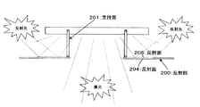
また、雰囲気のある照明にしたい場合は、図4に示すように、反射部200を筐体本体と平行に、かつ筐体本体下面より下げた位置に配置する。かかる配置により、正面方向への集中光と同時に筐体100の背面側への反射光を得ることができ、部屋が広く見えるようにすることが可能となり、雰囲気のある空間を作ることができる。
When it is desired to provide illumination with an atmosphere, as shown in FIG. 4, the reflecting portion 200 is disposed in parallel with the casing body and at a position lowered from the lower surface of the casing body. With such an arrangement, it is possible to obtain reflected light to the back side of the
さらにまた、不使用時には、図5に示すように、反射部200を開口面102に重ねるように配置する。
この構成により、長期で使用しない時など、反射部を完全に閉じた状態にすることで、反射部で筐体の開口面102を覆うことができるため、面状光源を保護することができる。
Furthermore, when not in use, as shown in FIG. 5, the reflecting portion 200 is disposed so as to overlap the
With this configuration, when the reflective portion is completely closed, such as when it is not used for a long time, the
本実施の形態の照明器具によれば、薄型でかつ多機能配光が可能な照明器具を提供することが可能となる。
また、別体の照明を設けることなくひとつの照明器具で反射光を効率よく利用し作業面を照明したり、部屋全体のムード照明を実現したりすることができるので、簡便であり、空間が煩雑にならない。また、面状光源からの光のみを有効活用できるので電気エネルギーアップにならずにすむ。
According to the lighting fixture of this Embodiment, it becomes possible to provide the lighting fixture which is thin and can perform multi-function light distribution.
In addition, it is possible to illuminate the work surface by efficiently using reflected light with a single luminaire without providing separate lighting, and to realize mood lighting of the entire room. Not complicated. In addition, since only the light from the planar light source can be used effectively, it is not necessary to increase electric energy.
ここで面状光源に用いる光源としては、有機エレクトロルミネッセンス(LED)素子のほか、無機LED素子、蛍光灯等を用いることができ、特に制限されるものではないが、面状発光装置を薄く形成でき、光色の可変性に優れる有機LED素子などのLED素子が好ましい。 Here, as the light source used for the planar light source, in addition to the organic electroluminescence (LED) element, an inorganic LED element, a fluorescent lamp, or the like can be used. Although not particularly limited, the planar light emitting device is formed thinly. An LED element such as an organic LED element that can be made and has excellent light color variability is preferable.
例えば、有機ELパネルの場合、有機発光層は、白色光を取り出せるように素子あるいは発光層が積層されていてもよいし、それぞれ赤色光、緑色光、青色光を発光する素子をまとめて調色できるようになっていてもよい。なお、有機発光層の発光色は一例であって、かかる発光色に限定されるものではない。 For example, in the case of an organic EL panel, the organic light emitting layer may be laminated with an element or a light emitting layer so that white light can be extracted, and the elements that emit red light, green light, and blue light are toned together. You may be able to. The light emission color of the organic light emitting layer is an example, and is not limited to such light emission color.
また、LEDパネルの場合、多数のLED光源が配列されている。各LED光源は、それぞれ赤色光、緑色光、青色光を発光するLED素子をまとめて1つの光源としてもよいし、各発光色で分けられていてもよい。なお、LED素子の発光色は一例であって、かかる発光色に限定されるものではない。なお、各LED素子に流す電流比率を制御することによって、光線の色成分を変化させることが可能である。 In the case of an LED panel, a large number of LED light sources are arranged. In each LED light source, LED elements that emit red light, green light, and blue light may be combined into one light source, or may be divided by each emission color. In addition, the light emission color of an LED element is an example, Comprising: It is not limited to this light emission color. In addition, it is possible to change the color component of a light beam by controlling the ratio of the current passed through each LED element.
ELパネルやLEDパネルは、それらのサイズに応じて、任意の数を筐体100の面状光源内に配置することができる。
上記のような光源の周縁に筐体や光透過パネルを配設し面状光源を形成する。筐体には壁、床等の電気配線と接続するための電気接点が設けられている。また、光透過パネルは、光源の上方に配設され、光源を発光させたときに、面状光源の発光面201となる。
An arbitrary number of EL panels and LED panels can be arranged in the planar light source of the
A planar light source is formed by arranging a casing and a light transmission panel on the periphery of the light source as described above. The casing is provided with electrical contacts for connecting to electrical wiring such as walls and floors. The light transmissive panel is disposed above the light source and becomes the light emitting surface 201 of the planar light source when the light source emits light.
さらにまた、面状光源としては、点光源をライン状に配列して面状発光装置の端部に配置し、導光板によって、この点光源からの光を床面に導き、面状光源として用いるようにしたものも適用可能である。 Furthermore, as the planar light source, point light sources are arranged in a line and arranged at the end of the planar light emitting device, and the light from the point light source is guided to the floor surface by the light guide plate and used as the planar light source. What was made is also applicable.
ここで、面状光源の筐体を構成する素材としては、プラスチックやこれらにガラス繊維などの強化充填材を配合したもの、アルミニウム合金、鉄、マグネシウム合金のような金属、木材など特に限定されるものではないが、割れにくい素材であることが望ましい。 Here, the material constituting the casing of the planar light source is particularly limited to plastics, those in which a reinforcing filler such as glass fiber is blended, metals such as aluminum alloy, iron, magnesium alloy, and wood. Although it is not a thing, it is desirable that the material is hard to break.
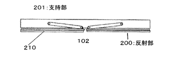
また、発光面となる開口面102を構成する光透過パネルの構成素材としては、透光性プラスチックやガラスなどが挙げられるが、所望の光学特性が得られ、発光面を所望の外観にできれば、特に限定されるものではない。また、消灯時に外観が必要な場合は、本発明の目的を損なわない範囲で、反射部200の一方の面を反射面としもう一方の面の反射面上に、図6に示すように、着脱可能なカバー板210を装着したものも有効である。この場合はカバー板210は、天井板壁などの外観に似せた素材で構成してもよい、また光透過パネルに擬似印刷したものを用いてもよい。
Moreover, examples of the constituent material of the light transmissive panel constituting the opening
(実施の形態2)
次にこの照明器具の変形例について説明する。
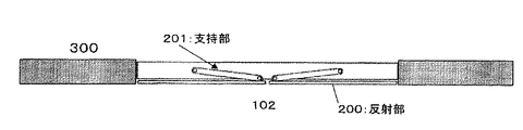
ここに示す照明器具は、図7に示すように、天井面300に筐体100を埋め込んだものである。
この場合も、室内を明るくしたい場合に、反射部200を展開し、面状光源からの光を床面に向けて反射する。ここでもこの反射部200は回動軸を軸として、180度回動可能である。回動軸には、適度な制動機構が内蔵されており、回動範囲内であれば、任意の角度で保持することが可能である。よって光の反射方向を制御することができるので作業面の位置が変化しても対応可能である。
(Embodiment 2)
Next, a modified example of this lighting apparatus will be described.
As shown in FIG. 7, the lighting fixture shown here has a
Also in this case, when it is desired to brighten the room, the reflection unit 200 is deployed to reflect the light from the planar light source toward the floor surface. Again, the reflecting portion 200 can be rotated 180 degrees around the rotation axis. An appropriate braking mechanism is built in the rotation shaft, and can be held at an arbitrary angle within the rotation range. Therefore, since the light reflection direction can be controlled, it is possible to cope with a change in the position of the work surface.
また、反射部200の形状、サイズは、所望の光学特性が得られれば特に限定されるものではない。
さらに、反射部200の光反射面は、鏡面、光拡散面など所望の光学特性が得られれば特に限定されるものではない。
この構成により、照明器具は天井面300に収納されるため、すっきりとしたインテリア空間を得ることができる。
Further, the shape and size of the reflecting portion 200 are not particularly limited as long as desired optical characteristics can be obtained.
Further, the light reflecting surface of the reflecting portion 200 is not particularly limited as long as desired optical characteristics such as a mirror surface and a light diffusing surface can be obtained.
With this configuration, since the lighting fixture is housed in the
(実施の形態3)
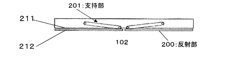
図8は本発明の実施の形態3に係る照明器具の説明図である。この照明器具は反射部の片面を反射面211とし、もう片面を非反射面212としたもので、他部の構成については前記実施の形態1の照明器具と同様であり、ここでは説明を省略した。
(Embodiment 3)
FIG. 8 is an explanatory diagram of a lighting fixture according to Embodiment 3 of the present invention. In this lighting fixture, one side of the reflecting portion is a reflecting
この構造によれば、図4に示した拡散光と照明光を得る配光はできないが、実施の形態1で説明した配光とは異なる配光形態をもつ種々の配光が実現可能である。 According to this structure, the light distribution that obtains the diffused light and the illumination light shown in FIG. 4 cannot be obtained, but various light distributions having a light distribution form different from that described in the first embodiment can be realized. .
上記実施の形態によれば、収納時は反射面は露呈していないため、反射面の汚染もなく、維持することができ、非反射面212を所望の模様や絵画とすることで、アクセントインテリアとしても有効である。
According to the above embodiment, the reflective surface is not exposed at the time of storage, so that the reflective surface is not contaminated and can be maintained, and the
100 筐体
101 面状光源
102 開口面
200(200a、200b) 反射部
202 第1の回動軸
203 第2の回動軸
DESCRIPTION OF
Claims (6)
前記開口面から発光可能に形成された面状の光源と、前記開口面の少なくとも一つの縁に取付けられ、
前記開口面に対して回動自在に取付けられた反射部とを具備した照明器具。 A housing having an opening surface;
A planar light source formed so as to be capable of emitting light from the opening surface, and attached to at least one edge of the opening surface;
A luminaire comprising a reflecting portion rotatably attached to the opening surface.
前記縁を軸として回動する支持部を具備し、
前記反射部は、前記支持部の当該縁と反対側の端部に取り付けられた照明器具。 The lighting fixture according to claim 1,
Comprising a support that pivots about the edge;
The said reflection part is a lighting fixture attached to the edge part on the opposite side to the said edge of the said support part.
前記光源は、開口面と略同じ形状の発光面を有する面状光源であり、
前記反射部は、前記筐体の任意の対称軸を挟んで、対向するように配置される照明器具。 The lighting apparatus according to claim 1 or 2,
The light source is a planar light source having a light emitting surface having substantially the same shape as the opening surface,
The said reflection part is a lighting fixture arrange | positioned so that it may oppose on both sides of the arbitrary symmetry axes of the said housing | casing.
前記光源は、有機エレクトロルミネッセンス素子である照明器具。 It is a lighting fixture in any one of Claims 1 thru | or 3, Comprising:
The lighting device is an organic electroluminescence element.
前記反射部は、一方の面のみが反射面で構成された反射板である照明器具。 It is a lighting fixture in any one of Claims 1 thru | or 4, Comprising:
The said reflection part is a lighting fixture which is a reflecting plate by which only one surface was comprised by the reflective surface.
前記反射部は、両面が反射面で構成された反射板である照明器具。 It is a lighting fixture in any one of Claims 1 thru | or 4, Comprising:
The said reflection part is a lighting fixture which is a reflecting plate by which both surfaces were comprised by the reflective surface.
Priority Applications (1)
| Application Number | Priority Date | Filing Date | Title |
|---|---|---|---|
| JP2008326008A JP2010146973A (en) | 2008-12-22 | 2008-12-22 | Lighting fixture |
Applications Claiming Priority (1)
| Application Number | Priority Date | Filing Date | Title |
|---|---|---|---|
| JP2008326008A JP2010146973A (en) | 2008-12-22 | 2008-12-22 | Lighting fixture |
Publications (2)
| Publication Number | Publication Date |
|---|---|
| JP2010146973A true JP2010146973A (en) | 2010-07-01 |
| JP2010146973A5 JP2010146973A5 (en) | 2012-02-02 |
Family
ID=42567143
Family Applications (1)
| Application Number | Title | Priority Date | Filing Date |
|---|---|---|---|
| JP2008326008A Pending JP2010146973A (en) | 2008-12-22 | 2008-12-22 | Lighting fixture |
Country Status (1)
| Country | Link |
|---|---|
| JP (1) | JP2010146973A (en) |
Cited By (8)
| Publication number | Priority date | Publication date | Assignee | Title |
|---|---|---|---|---|
| JP2012129164A (en) * | 2010-12-17 | 2012-07-05 | Toshiba Lighting & Technology Corp | Lighting device |
| CN103047570A (en) * | 2012-12-25 | 2013-04-17 | 宁波友康照明电器有限公司 | Led lamp |
| CN106838716A (en) * | 2016-12-25 | 2017-06-13 | 重庆比阳产品设计有限公司 | Plasticine model search lighting device |
| CN107166279A (en) * | 2017-07-17 | 2017-09-15 | 中山爱奇光电科技有限公司 | Mirror reflection regulation formula LED ceiling light |
| CN107477523A (en) * | 2017-09-07 | 2017-12-15 | 深圳市尚为照明有限公司 | A kind of device for being provided simultaneously with double optics luminous intensity distribution |
| US10054288B2 (en) | 2015-12-04 | 2018-08-21 | Dyson Technology Limited | Lighting device |
| EP2999920B1 (en) | 2012-05-15 | 2018-10-03 | Musco Corporation | Apparatus, method, and system for independent aiming and cutoff steps in illuminating a target area |
| JP2019145250A (en) * | 2018-02-16 | 2019-08-29 | 清水建設株式会社 | Building interior space and control device of building interior space environment |
Citations (6)
| Publication number | Priority date | Publication date | Assignee | Title |
|---|---|---|---|---|
| JPH0836907A (en) * | 1994-07-22 | 1996-02-06 | Agency Of Ind Science & Technol | Lighting equipment |
| JP2002075044A (en) * | 2000-09-01 | 2002-03-15 | Matsushita Electric Works Ltd | Lighting equipment |
| JP2002148555A (en) * | 2000-11-14 | 2002-05-22 | Ushio Inc | Light irradiation device |
| JP2002270007A (en) * | 2001-03-08 | 2002-09-20 | Rabo Sufia Kk | Foldable planar light emitting device and planar display device |
| JP2007173053A (en) * | 2005-12-22 | 2007-07-05 | Matsushita Electric Works Ltd | Lighting system |
| WO2009072386A1 (en) * | 2007-12-06 | 2009-06-11 | Konica Minolta Holkings, Inc. | Lighting unit panel |
-
2008
- 2008-12-22 JP JP2008326008A patent/JP2010146973A/en active Pending
Patent Citations (6)
| Publication number | Priority date | Publication date | Assignee | Title |
|---|---|---|---|---|
| JPH0836907A (en) * | 1994-07-22 | 1996-02-06 | Agency Of Ind Science & Technol | Lighting equipment |
| JP2002075044A (en) * | 2000-09-01 | 2002-03-15 | Matsushita Electric Works Ltd | Lighting equipment |
| JP2002148555A (en) * | 2000-11-14 | 2002-05-22 | Ushio Inc | Light irradiation device |
| JP2002270007A (en) * | 2001-03-08 | 2002-09-20 | Rabo Sufia Kk | Foldable planar light emitting device and planar display device |
| JP2007173053A (en) * | 2005-12-22 | 2007-07-05 | Matsushita Electric Works Ltd | Lighting system |
| WO2009072386A1 (en) * | 2007-12-06 | 2009-06-11 | Konica Minolta Holkings, Inc. | Lighting unit panel |
Cited By (10)
| Publication number | Priority date | Publication date | Assignee | Title |
|---|---|---|---|---|
| JP2012129164A (en) * | 2010-12-17 | 2012-07-05 | Toshiba Lighting & Technology Corp | Lighting device |
| EP2999920B1 (en) | 2012-05-15 | 2018-10-03 | Musco Corporation | Apparatus, method, and system for independent aiming and cutoff steps in illuminating a target area |
| CN103047570A (en) * | 2012-12-25 | 2013-04-17 | 宁波友康照明电器有限公司 | Led lamp |
| US10054288B2 (en) | 2015-12-04 | 2018-08-21 | Dyson Technology Limited | Lighting device |
| CN106838716A (en) * | 2016-12-25 | 2017-06-13 | 重庆比阳产品设计有限公司 | Plasticine model search lighting device |
| CN106838716B (en) * | 2016-12-25 | 2018-12-28 | 重庆比阳产品设计有限公司 | Plasticine model search lighting device |
| CN107166279A (en) * | 2017-07-17 | 2017-09-15 | 中山爱奇光电科技有限公司 | Mirror reflection regulation formula LED ceiling light |
| CN107477523A (en) * | 2017-09-07 | 2017-12-15 | 深圳市尚为照明有限公司 | A kind of device for being provided simultaneously with double optics luminous intensity distribution |
| JP2019145250A (en) * | 2018-02-16 | 2019-08-29 | 清水建設株式会社 | Building interior space and control device of building interior space environment |
| JP7012554B2 (en) | 2018-02-16 | 2022-02-14 | 清水建設株式会社 | Control device for the space inside the building and the space inside the building |
Similar Documents
| Publication | Publication Date | Title |
|---|---|---|
| JP2010146973A (en) | Lighting fixture | |
| US9574750B1 (en) | Single axis adjustment for emergency lights emitting an asymmetric beam pattern to illuminate a path of egress | |
| JP5450008B2 (en) | lighting equipment | |
| JP2009289709A (en) | Ceiling direct attachment type illumination device and illumination device | |
| JP2008073174A (en) | Mirror with illumination | |
| JP2009266780A (en) | Luminous body and luminaire | |
| CN205299287U (en) | Light emitting unit | |
| JP2009009826A (en) | Lighting device | |
| JP2010205482A (en) | Luminaire | |
| EP1792119B1 (en) | Luminaire with louver members | |
| KR19990008256U (en) | Interior decoration landfill | |
| JP6887122B2 (en) | Lighting system | |
| JP4547736B2 (en) | Lighting method and lighting apparatus | |
| JP4491327B2 (en) | lighting equipment | |
| JP2008135202A (en) | lighting equipment | |
| KR200385055Y1 (en) | Lighting equiped with subsidisary luminous system using LED | |
| CN119301404A (en) | Lighting arrangement with rotatable lighting units | |
| JP4634944B2 (en) | lighting equipment | |
| CN215982385U (en) | Lighting device | |
| KR20130073619A (en) | Lighting apparatus | |
| KR200400245Y1 (en) | Illuminator | |
| JP2010073397A (en) | Floor surface light emitting system | |
| KR102203057B1 (en) | Lighting lamp for event | |
| JP5246410B2 (en) | lighting equipment | |
| JP7165881B2 (en) | Luminaires and lighting systems |
Legal Events
| Date | Code | Title | Description |
|---|---|---|---|
| A621 | Written request for application examination |
Free format text: JAPANESE INTERMEDIATE CODE: A621 Effective date: 20111118 |
|
| A521 | Written amendment |
Free format text: JAPANESE INTERMEDIATE CODE: A523 Effective date: 20111207 |
|
| A711 | Notification of change in applicant |
Free format text: JAPANESE INTERMEDIATE CODE: A712 Effective date: 20120111 |
|
| A131 | Notification of reasons for refusal |
Free format text: JAPANESE INTERMEDIATE CODE: A131 Effective date: 20130129 |
|
| A02 | Decision of refusal |
Free format text: JAPANESE INTERMEDIATE CODE: A02 Effective date: 20130604 |