JP2005297723A - Telescopic shaft for vehicle steering - Google Patents
Telescopic shaft for vehicle steering Download PDFInfo
- Publication number
- JP2005297723A JP2005297723A JP2004115785A JP2004115785A JP2005297723A JP 2005297723 A JP2005297723 A JP 2005297723A JP 2004115785 A JP2004115785 A JP 2004115785A JP 2004115785 A JP2004115785 A JP 2004115785A JP 2005297723 A JP2005297723 A JP 2005297723A
- Authority
- JP
- Japan
- Prior art keywords
- shaft
- male
- female
- axial
- male shaft
- Prior art date
- Legal status (The legal status is an assumption and is not a legal conclusion. Google has not performed a legal analysis and makes no representation as to the accuracy of the status listed.)
- Granted
Links
Images


Classifications
-
- F—MECHANICAL ENGINEERING; LIGHTING; HEATING; WEAPONS; BLASTING
- F16—ENGINEERING ELEMENTS AND UNITS; GENERAL MEASURES FOR PRODUCING AND MAINTAINING EFFECTIVE FUNCTIONING OF MACHINES OR INSTALLATIONS; THERMAL INSULATION IN GENERAL
- F16C—SHAFTS; FLEXIBLE SHAFTS; ELEMENTS OR CRANKSHAFT MECHANISMS; ROTARY BODIES OTHER THAN GEARING ELEMENTS; BEARINGS
- F16C3/00—Shafts; Axles; Cranks; Eccentrics
- F16C3/02—Shafts; Axles
- F16C3/03—Shafts; Axles telescopic
- F16C3/035—Shafts; Axles telescopic with built-in bearings
-
- F—MECHANICAL ENGINEERING; LIGHTING; HEATING; WEAPONS; BLASTING
- F16—ENGINEERING ELEMENTS AND UNITS; GENERAL MEASURES FOR PRODUCING AND MAINTAINING EFFECTIVE FUNCTIONING OF MACHINES OR INSTALLATIONS; THERMAL INSULATION IN GENERAL
- F16C—SHAFTS; FLEXIBLE SHAFTS; ELEMENTS OR CRANKSHAFT MECHANISMS; ROTARY BODIES OTHER THAN GEARING ELEMENTS; BEARINGS
- F16C29/00—Bearings for parts moving only linearly
- F16C29/007—Hybrid linear bearings, i.e. including more than one bearing type, e.g. sliding contact bearings as well as rolling contact bearings
-
- F—MECHANICAL ENGINEERING; LIGHTING; HEATING; WEAPONS; BLASTING
- F16—ENGINEERING ELEMENTS AND UNITS; GENERAL MEASURES FOR PRODUCING AND MAINTAINING EFFECTIVE FUNCTIONING OF MACHINES OR INSTALLATIONS; THERMAL INSULATION IN GENERAL
- F16C—SHAFTS; FLEXIBLE SHAFTS; ELEMENTS OR CRANKSHAFT MECHANISMS; ROTARY BODIES OTHER THAN GEARING ELEMENTS; BEARINGS
- F16C29/00—Bearings for parts moving only linearly
- F16C29/04—Ball or roller bearings
-
- F—MECHANICAL ENGINEERING; LIGHTING; HEATING; WEAPONS; BLASTING
- F16—ENGINEERING ELEMENTS AND UNITS; GENERAL MEASURES FOR PRODUCING AND MAINTAINING EFFECTIVE FUNCTIONING OF MACHINES OR INSTALLATIONS; THERMAL INSULATION IN GENERAL
- F16C—SHAFTS; FLEXIBLE SHAFTS; ELEMENTS OR CRANKSHAFT MECHANISMS; ROTARY BODIES OTHER THAN GEARING ELEMENTS; BEARINGS
- F16C29/00—Bearings for parts moving only linearly
- F16C29/12—Arrangements for adjusting play
- F16C29/123—Arrangements for adjusting play using elastic means
-
- F—MECHANICAL ENGINEERING; LIGHTING; HEATING; WEAPONS; BLASTING
- F16—ENGINEERING ELEMENTS AND UNITS; GENERAL MEASURES FOR PRODUCING AND MAINTAINING EFFECTIVE FUNCTIONING OF MACHINES OR INSTALLATIONS; THERMAL INSULATION IN GENERAL
- F16C—SHAFTS; FLEXIBLE SHAFTS; ELEMENTS OR CRANKSHAFT MECHANISMS; ROTARY BODIES OTHER THAN GEARING ELEMENTS; BEARINGS
- F16C2326/00—Articles relating to transporting
- F16C2326/20—Land vehicles
- F16C2326/24—Steering systems, e.g. steering rods or columns
Landscapes
- Engineering & Computer Science (AREA)
- General Engineering & Computer Science (AREA)
- Mechanical Engineering (AREA)
- Ocean & Marine Engineering (AREA)
- Steering Controls (AREA)
- Sliding-Contact Bearings (AREA)
- Support Of The Bearing (AREA)
- Bearings For Parts Moving Linearly (AREA)
Abstract
Description
本発明は、車両のステアリングシャフトに組込み、雄軸と雌軸を相互に回転不能に且つ摺動自在に嵌合した車両ステアリング用伸縮軸に関する。 The present invention relates to a telescopic shaft for vehicle steering that is incorporated in a steering shaft of a vehicle and has a male shaft and a female shaft that are non-rotatable and slidably fitted to each other.
従来、自動車の操舵機構部では、自動車が走行する際に発生する軸方向の変位を吸収し、ステアリングホイール上にその変位や振動を伝えないために雄軸と雌軸とをスプライン嵌合した伸縮軸を操舵機構部の一部に使用している。伸縮軸にはスプライン部のガタ音を低減することと、ステアリングホイール上のガタ感を低減することと、軸方向摺動時における摺動抵抗を低減することが要求される。 Conventionally, the steering mechanism part of an automobile absorbs the displacement in the axial direction that occurs when the automobile travels, and the expansion and contraction is a spline fit between the male shaft and the female shaft in order not to transmit the displacement or vibration on the steering wheel. The shaft is used as part of the steering mechanism. The telescopic shaft is required to reduce the rattling noise of the spline part, to reduce the rattling on the steering wheel, and to reduce the sliding resistance when sliding in the axial direction.
このようなことから、伸縮軸の雄軸のスプライン部に対して、ナイロン膜をコーティングし、さらに摺動部にグリースを塗布し、金属騒音、金属打音等を吸収または緩和すると共に摺動抵抗の低減と回転方向ガタの低減を行ってきた。この場合、ナイロン膜を形成する工程としてはシャフトの洗浄→プライマー塗布→加熱→ナイロン粉末コート→粗切削→仕上げ切削→雌軸との選択嵌合が行われている。最終の切削加工は、既に加工済みの雌軸の精度に合わせてダイスを選択して加工を行っている。 Because of this, the nylon spline part of the telescopic shaft is coated with nylon film, and grease is applied to the sliding part to absorb or reduce metal noise, metal hitting sound, etc., and sliding resistance Have been reduced and the play in the rotational direction has been reduced. In this case, as a process of forming the nylon film, cleaning of the shaft → primer application → heating → nylon powder coating → rough cutting → finish cutting → selective fitting with the female shaft is performed. The final cutting process is performed by selecting a die in accordance with the accuracy of the already processed female shaft.
また、特許文献1の請求項6では、ある遊びをもった組み合わせ断面を有する雄部および雌部が内側軸および外側軸に設けられ、その結果、ボールの破損時でも、内側軸と外側軸との間でトルクの伝達を行なうことができるようになっている。
Further, in
さらに、特許文献2では、スプライン部に、コーティングをすることで、ガタなく、スライド時の摺動抵抗を低く抑えようとしている。
特許文献1では、通常使用時は、複数のボールが転がりによる伸縮運動とトルク伝達を行なっている。このため、構造上、入力トルクに耐えるだけのボール数を備えていなければならず、システムとしてのコンパクト化が困難である。 In Patent Document 1, during normal use, a plurality of balls perform expansion and contraction motion and torque transmission by rolling. For this reason, structurally, it must have the number of balls that can withstand the input torque, and it is difficult to make the system compact.
よって、車両衝突時に、十分なコラプス・ストロークをとることが困難であるという構造上の不利な点がある。 Therefore, there is a structural disadvantage that it is difficult to take a sufficient collapse stroke at the time of a vehicle collision.
そのため、フェイル・セーフ機能として、このような、ボールが破損した際にシャフトの空転を防止するためのあるあそびをもった組み合わせ断面が必要になると推察される。 Therefore, it is presumed that a combined cross section having a certain play for preventing the slipping of the shaft when the ball is broken is necessary as a fail-safe function.
また、特許文献1の本構造の場合、ボールに予圧を与えてガタつきを防止しているが、本構造の場合、摺動荷重が変動するといったステアリング用シャフトとしては、好ましくない特性が現れてしまう。 In the case of the main structure of Patent Document 1, preload is applied to the ball to prevent rattling, but in the case of this structure, an undesirable characteristic appears as a steering shaft in which the sliding load fluctuates. End up.
さらに、特許文献2では、トルクが負荷された瞬間から、スライド荷重が急激に上昇するといった問題がある。
Furthermore, in
特に、ジョイントに角度がついた状態(車両で使われる通常の使用状態)で、トルクが負荷されると、雄軸と雌軸には、こじれが生じて、スプラインの端面が雌軸の摺動面に食いついて、スライド荷重を上昇させる原因となり得る。 In particular, when torque is applied in a state where the joint is angled (normal use state used in a vehicle), the male shaft and the female shaft are twisted, and the end surface of the spline slides on the female shaft. It can cause the slide load to increase by biting the surface.
さらに、このような伸縮軸では、システムのコンパクト化を図り、車両衝突時のコラプス・ストロークが十分とれること、摺動変動を低減して、転がりと滑り摺動特性の優れた両特性(低摺動荷重と低荷重変動)を有すること、及び、軽量にできること等の要望もある。 Furthermore, with such a telescopic shaft, the compactness of the system is achieved, the collapse stroke at the time of the vehicle collision is sufficient, the sliding fluctuation is reduced, and both characteristics of excellent rolling and sliding sliding characteristics (low sliding) There are also demands such as having a dynamic load and low load fluctuation) and being able to be light.
本発明は、上述したような事情に鑑みてなされたものであって、例えば、トルク伝達時に軸直角方向の力が作用して、雄軸と雌軸にこじれが生じても、トルク伝達部である滑り摺動面がスティック・スリップを生起することなく、スムーズにスライドすることができる、車両ステアリング用伸縮軸を提供することを目的とする。 The present invention has been made in view of the circumstances as described above. For example, even if a force in a direction perpendicular to the axis acts during torque transmission and the male shaft and the female shaft are twisted, the torque transmission portion An object of the present invention is to provide a telescopic shaft for vehicle steering that allows a certain sliding surface to slide smoothly without causing stick-slip.
上記の目的を達成するため、本発明の請求項1に係る車両ステアリング用伸縮軸は、車両のステアリングシャフトに組込み、雄軸と雌軸を回転不能に且つ摺動自在に嵌合した車両ステアリング用伸縮軸において、
前記雄軸の外周部と前記雌軸の内周部にそれぞれ設けられ、回転の際には互いに接触してトルクを伝達するトルク伝達部と、
前記トルク伝達部とは異なる位置の前記雄軸の外周部と前記雌軸の内周部の間に設けられ、前記雄軸と前記雌軸との軸方向相対移動の際には転動する転動体と、該転動体に径方向に隣接して配置され、該転動体を介して前記雄軸と前記雌軸とに予圧を与える弾性体とからなる予圧部と、を具備し、
前記トルク伝達部に於ける前記雄軸の外周部と前記雌軸の内周部とは、微少な所定間隔の隙間を維持しつつ、
前記トルク伝達部の前記雄軸は、曲面形状を有していることを特徴とする車両ステアリング用伸縮軸。
In order to achieve the above object, a telescopic shaft for vehicle steering according to claim 1 of the present invention is incorporated in a steering shaft of a vehicle, and is used for vehicle steering in which a male shaft and a female shaft are fitted non-rotatably and slidably. In the telescopic axis,
A torque transmitting portion provided on each of the outer peripheral portion of the male shaft and the inner peripheral portion of the female shaft, and in contact with each other at the time of rotation;
Roller that is provided between the outer peripheral part of the male shaft and the inner peripheral part of the female shaft at a position different from the torque transmission part, and rolls when the male shaft and the female shaft move relative to each other in the axial direction. A moving body, and a preload portion that is arranged adjacent to the rolling element in the radial direction and includes an elastic body that applies preload to the male shaft and the female shaft via the rolling body,
In the torque transmission portion, the outer peripheral portion of the male shaft and the inner peripheral portion of the female shaft are maintained with a small predetermined gap,
The telescopic shaft for vehicle steering, wherein the male shaft of the torque transmitting portion has a curved surface shape.
本発明の請求項2に係る車両ステアリング用伸縮軸は、前記トルク伝達部は、前記雄軸の外周面に形成された軸方向凸条と、前記雌軸の内周面に形成された軸方向溝と、からなることを特徴とする。
The telescopic shaft for vehicle steering according to
本発明の請求項3に係る車両ステアリング用伸縮軸は、前記トルク伝達部の前記雄軸の軸方向凸条は、その端部がテーパー形状であり、その角部が曲面により形成してあることを特徴とする。
In the telescopic shaft for vehicle steering according to
本発明の請求項4に係る車両ステアリング用伸縮軸は、前記雄軸の外周面に、低摩擦の固体潤滑皮膜が形成されていることを特徴とする。 A telescopic shaft for vehicle steering according to a fourth aspect of the present invention is characterized in that a low-friction solid lubricating film is formed on the outer peripheral surface of the male shaft.
本発明の請求項5に係る車両ステアリング用伸縮軸は、車両のステアリングシャフトに組込み、雄軸と雌軸を回転不能に且つ摺動自在に嵌合した車両ステアリング用伸縮軸において、
前記雄軸の外周部と前記雌軸の内周部にそれぞれ設けられ、回転の際には互いに接触してトルクを伝達するトルク伝達部と、
前記トルク伝達部とは異なる位置の前記雄軸の外周部と前記雌軸の内周部の間に設けられ、前記雄軸と前記雌軸との軸方向相対移動の際には転動する転動体と、該転動体に径方向に隣接して配置され、該転動体を介して前記雄軸と前記雌軸とに予圧を与える弾性体とからなる予圧部と、を具備し、
前記トルク伝達部に於ける前記雄軸の外周部と前記雌軸の内周部とは、微少な所定間隔の隙間を維持しつつ、
前記トルク伝達部の前記雄軸及び前記雌軸は、夫々、曲面形状を有していることを特徴とする。
A telescopic shaft for vehicle steering according to
A torque transmitting portion provided on each of the outer peripheral portion of the male shaft and the inner peripheral portion of the female shaft, and in contact with each other at the time of rotation;
Roller that is provided between the outer peripheral part of the male shaft and the inner peripheral part of the female shaft at a position different from the torque transmission part, and rolls when the male shaft and the female shaft move relative to each other in the axial direction. A moving body, and a preload portion that is arranged adjacent to the rolling element in the radial direction and includes an elastic body that applies preload to the male shaft and the female shaft via the rolling body,
In the torque transmission portion, the outer peripheral portion of the male shaft and the inner peripheral portion of the female shaft are maintained with a small predetermined gap,
The male shaft and the female shaft of the torque transmission unit each have a curved surface shape.
本発明の請求項6に係る車両ステアリング用伸縮軸は、前記トルク伝達部は、前記雄軸の外周面に形成された軸方向凸条と、前記雌軸の内周面に形成された軸方向溝と、からなることを特徴とする。
The telescopic shaft for vehicle steering according to
本発明の請求項7に係る車両ステアリング用伸縮軸は、前記トルク伝達部の前記雄軸の軸方向凸条は、その端部がテーパー形状であり、その角部が曲面により形成してあり、
前記トルク伝達部の前記雌軸の軸方向溝は、二つの軸方向溝の間に形成される凸条と、軸方向溝の端側の立壁部とで、その角部が曲面により形成してあることを特徴とする。
In the telescopic shaft for vehicle steering according to claim 7 of the present invention, the axial ridge of the male shaft of the torque transmitting portion has a tapered end, and a corner formed by a curved surface.
The axial groove of the female shaft of the torque transmission part is formed by a convex line formed between two axial grooves and a standing wall part on the end side of the axial groove, and the corner part is formed by a curved surface. It is characterized by being.
本発明の請求項8に係る車両ステアリング用伸縮軸は、前記雄軸の外周面に、低摩擦の固体潤滑皮膜が形成されていることを特徴とする。 A telescopic shaft for vehicle steering according to an eighth aspect of the present invention is characterized in that a low-friction solid lubricating film is formed on the outer peripheral surface of the male shaft.
転動体と予圧部の組合せと、トルク伝達部の組合せの場合、トルク伝達部である滑り摺動面は、雄軸と雌軸との間に、スムーズにスライドできるだけの微少な所定間隔の隙間を設ける必要がある。しかし、このような隙間を設けることにより、雄軸と雌軸は、倒れ角が大きくなるため、例えば、トルク伝達時に軸直角方向の力が作用した場合、雄軸と雌軸にこじれが生じ易くなるといったことがある。 In the case of a combination of a rolling element and a preload portion and a torque transmission portion, the sliding surface that is the torque transmission portion has a small gap between the male shaft and the female shaft that can slide smoothly. It is necessary to provide it. However, by providing such a gap, the tilt angle between the male shaft and the female shaft increases. For example, when a force in a direction perpendicular to the axis acts during torque transmission, the male shaft and the female shaft are likely to be twisted. There is such a thing.
これを防止するため、本発明によれば、トルク伝達部の雄軸は、曲面形状を有している。これにより、こじれが生じたときの接触面のくさび効果が低減され、かじりによるスライド荷重の上昇を抑えることができる。従って、トルク伝達部である滑り摺動面がスティック・スリップを生起することなく、スムーズにスライドすることができる。 In order to prevent this, according to the present invention, the male shaft of the torque transmitting portion has a curved surface shape. As a result, the wedge effect of the contact surface when twisting occurs is reduced, and an increase in slide load due to galling can be suppressed. Therefore, the sliding surface that is the torque transmitting portion can smoothly slide without causing stick-slip.
以下、本発明の実施の形態に係る車両ステアリング用伸縮軸を図面を参照しつつ説明する。 Hereinafter, a telescopic shaft for vehicle steering according to an embodiment of the present invention will be described with reference to the drawings.
(車両用ステアリングシャフトの全体構成)
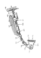
図1は、本発明の実施の形態に係る車両ステアリング用伸縮軸を適用した自動車の操舵機構部の側面図である。
(Overall configuration of vehicle steering shaft)
FIG. 1 is a side view of a steering mechanism portion of an automobile to which a vehicle steering telescopic shaft according to an embodiment of the present invention is applied.
図1において、車体側のメンバ100にアッパブラケット101とロアブラケット102とを介して取り付けられたアッパステアリングシャフト部120(ステアリングコラム103と、ステアリングコラム103に回転自在に保持されたスアリングシャフト104を含む)と、ステアリングシャフト104の上端に装着されたステアリングホイール105と、ステアリングシャフト104の下端にユニバーサルジョイント106を介して連結されたロアステアリングシャフト部107と、ロアステアリングシャフト部107に操舵軸継手108を介して連結されたピニオンシャフト109と、ピニオンシャフト109に連結したステアリングラック軸112と、このステアリングラック軸112を支持して車体の別のフレーム110に弾性体111を介して固定されたステアリングラック支持部材113とから操舵機構部が構成されている。
In FIG. 1, an upper steering shaft portion 120 (a
ここで、アッパステアリングシャフト部120とロアステアリングシャフト部107が本発明の実施の形態に係る車両ステアリング用伸縮軸(以後、伸縮軸と記す)を用いている。ロアステアリングシャフト部107は、雄軸と雌軸とを嵌合したものであるが、このようなロアステアリングシャフト部107には自動車が走行する際に発生する軸方向の変位を吸収し、ステアリングホイール105上にその変位や振動を伝えない性能が要求される。このような性能は、車体がサブフレーム構造となっていて、操舵機構上部を固定するメンバ100とステアリングラック支持部材113が固定されているフレーム110が別体となっておりステアリングラック支持部材113がゴムなどの弾性体111を介してフレーム110に締結固定されている構造の場合に要求される。また、その他のケースとして操舵軸継手108をピニオンシャフト109に締結する際に作業者が、伸縮軸をいったん縮めてからピニオンシャフト109に嵌合させ締結させるため伸縮機能が必要とされる場合がある。さらに、操舵機構の上部にあるアッパステアリングシャフト部120も、雄軸と雌軸とを嵌合したものであるが、このようなアッパステアリングシャフト部120には、運転者が自動車を運転するのに最適なポジションを得るためにステアリングホイール105の位置を軸方向に移動し、その位置を調整する機能が要求されるため、軸方向に伸縮する機能が要求される。前述のすべての場合において、伸縮軸には嵌合部のガタ音を低減することと、ステアリングホイール105上のガタ感を低減することと、軸方向摺動時における摺動抵抗を低減することが要求される。
Here, the upper
(第1実施の形態)
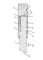
図2は、本発明の第1実施の形態に係る車両ステアリング用伸縮軸の横断面図である。図3は、図2のIII−III線に沿った断面図である。
(First embodiment)
FIG. 2 is a transverse sectional view of the telescopic shaft for vehicle steering according to the first embodiment of the present invention. FIG. 3 is a sectional view taken along line III-III in FIG.
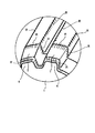
図4は、図2のIII−III線に沿った断面図であって、雄軸に、時計回り方向に「こじれ」が生じた時の作用図である。図5は、図2のIII−III線に沿った断面図であって、雄軸に、反時計回り方向に「こじれ」が生じた時の作用図である。図6は、雄軸の端部の部分的拡大斜視図である。 FIG. 4 is a cross-sectional view taken along the line III-III in FIG. 2, and is an operation diagram when a “twist” occurs in the clockwise direction on the male shaft. FIG. 5 is a cross-sectional view taken along the line III-III in FIG. 2, and is an operation diagram when “twist” occurs in the counterclockwise direction on the male shaft. FIG. 6 is a partially enlarged perspective view of the end portion of the male shaft.
図2、図3に示すように、車両ステアリング用伸縮軸(以後、伸縮軸と記す)は、相互に回転不能に且つ摺動自在に嵌合した雄軸1と雌軸2とからなる。
As shown in FIGS. 2 and 3, the telescopic shaft for vehicle steering (hereinafter referred to as the telescopic shaft) includes a male shaft 1 and a
本実施の形態では、雄軸1の外周面には、複数個の軸方向凸条4が延在して形成してある。これら軸方向凸条4は、スプライン嵌合の雄部であるが、セレーション嵌合の雄部であっても、又は単に凸凹嵌合用であってもよい。
In the present embodiment, a plurality of
雌軸2の内周面には、雄軸1の軸方向凸条4に対向する位置に、複数個の軸方向溝6が延在して形成してある。これら軸方向溝6は、スプライン嵌合の雌部であるが、セレーション嵌合の雌部であっても、又は単に凸凹嵌合用であってもよい。
A plurality of
なお、上述した軸方向凸条4と軸方向溝6とは、特許請求の範囲の請求項1に記載した本発明の構成要件であるトルク伝達部を構成している。
In addition, the
雄軸1の外周面には、周方向に120度間隔(位相)で等配した3個の軸方向溝3が延在して形成してある。これに対応して、雌軸2の内周面にも、周方向に120度間隔(位相)で等配した3個の軸方向溝5が延在して形成してある。
On the outer peripheral surface of the male shaft 1, three
雄軸1の軸方向溝3と、雌軸2の軸方向溝5との間に、両軸1,2の軸方向相対移動の際に転動する複数の剛体の球状体7(転動体、ボール)が転動自在に介装してある。なお、雌軸2の軸方向溝5は、断面略円弧状若しくはゴシックアーチ状である。
Between the
雄軸1の軸方向溝3は、傾斜した一対の平面状側面3aと、これら一対の平面状側面3aの間に平坦に形成した底面3bとから構成してある。
The
雄軸1の軸方向溝3と、球状体7との間には、球状体7に接触して予圧するための弾性体8が介装してある。
Between the
この弾性体8は、球状体7に2点で略円弧形状で接触する球状体側接触部8aと、球状体側接触部8aに対して略周方向に所定間隔をおいて離間してあると共に雄軸1の軸方向溝3の平面状側面3aに接触する溝面側接触部8bと、球状体側接触部8aと溝面側接触部8bを相互に離間する方向に弾性的に付勢する付勢部8cと、軸方向溝3の底面3bに対向した底部8dと、を有している。
The
この付勢部8cは、略U字形状で略円弧状に折曲した折曲形状であり、この折曲形状の付勢部8cによって、球状体側接触部8aと溝面側接触部8bを相互に離間するように弾性的に付勢することができる。
The urging
雄軸1が雌軸2に挿入される側の端部には、弾性体8が脱落しない様に微少すきまをもって、弾性体8を係止して軸方向に固定するストッパープレート9が加締め部10により雄軸1に加締められている。このストッパープレート9は転動体7a,7nが雄軸1の軸方向溝3から外れないようにする働きもしている。このようにして本実施の形態の車両ステアリング用伸縮軸が構成されている。
A
上記のような伸縮軸に於いて、軸回転時(高トルク伝達時)には、軸方向凸条4と、軸方向溝6とは、互いに接触してトルク伝達部を構成する。
In the telescopic shaft as described above, when the shaft rotates (at the time of high torque transmission), the
本実施の形態の伸縮軸は、このような構造であるので、予圧部の存在によりそれぞれのトルク伝達部において雄軸1と雌軸2は常時摺動可能に接触しており、雄軸1と雌軸2との軸方向の相対移動の際には互いに摺動し、且つ転動体7は転動することが出来る。
Since the telescopic shaft of the present embodiment has such a structure, the male shaft 1 and the
なお、雄軸に形成されている軸方向凸条4が雌軸側に、雌軸に形成されている軸方向溝6が雄軸側に形成されていても本実施の形態と同様の作用、効果が得られる。また、軸方向溝5の曲率と転動体7の曲率が異なっていて、両者は点接触するように形成されていても良い。また、転動体7は球状体であっても良い。さらに、弾性体8は板バネであっても良い。また、摺動面および転動面にグリースを塗布することによりさらに低い摺動荷重を得ることが出来る。
Even if the
このように構成された本実施の形態の伸縮軸は、以下の点が従来技術に比べ優れている。 The telescopic shaft of the present embodiment configured as described above is superior to the prior art in the following points.
従来技術のように摺動面が純粋な滑りによるものであれば、ガタつき防止のための予圧荷重をある程度の荷重で留めておくことしかできなかった。それは、摺動荷重は、摩擦係数に予圧荷重を乗じたものであり、ガタつき防止や伸縮軸の剛性を向上させたいと願って予圧荷重を上げてしまうと摺動荷重が増大してしまうという悪循環に陥ってしまうためである。 If the sliding surface is purely sliding as in the prior art, the preload load for preventing rattling could only be kept at a certain level. That is, the sliding load is the friction coefficient multiplied by the preload, and if the preload is increased to prevent rattling and improve the rigidity of the telescopic shaft, the sliding load will increase. This is because it falls into a vicious circle.
その点、本実施の形態では、予圧部は軸方向の相対移動の際には、転動体7の転動機構を採用しているため、著しい摺動荷重の増大を招くことなく予圧荷重を上げることができる。これにより、従来なし得なかったガタつきの防止と剛性の向上を摺動荷重の増大を招くことなく達成することができる。
In this respect, in the present embodiment, the preload portion employs a rolling mechanism of the rolling
そして、高トルク伝達時には、トルク伝達部の軸方向凸条4が軸方向溝6に接触することによってトルク伝達の役割を果たし、予圧部では弾性体8が弾性変形して球状体7を雄軸1と雌軸2の間で周方向に拘束してガタつきを防止すると共に、低トルクを伝達する。
At the time of high torque transmission, the
例えば、雄軸1からトルクが入力された場合、初期の段階では、弾性体8の予圧が加わっているため、ガタつきを防止する。
For example, when torque is input from the male shaft 1, rattling is prevented since the preload of the
さらにトルクが増大していくと、トルク伝達部の軸方向凸条4と軸方向溝6の側面が強く接触し、軸方向凸条4の方が球状体7より反力を強く受け、トルク伝達部が主にトルクを伝達する。そのため、本実施の形態では、雄軸1と雌軸2の回転方向ガタを確実に防止すると共に、高剛性の状態でトルクを伝達することができる。
As the torque further increases, the
また、軸方向凸条4と軸方向溝6とは、トルク伝達時には、軸方向に連続して接触してその荷重を受けるため、点接触で荷重を受ける転動体7よりも接触圧を低く抑えることができるなど、さまざまな効果がある。したがって、全列をボール転がり構造とした従来例に比べ下記の項目が優れている。
・摺動部での減衰能効果が、ボール転がり構造に比べて大きい。よって振動吸収性能が高い。
・同じトルクを伝達するならば、軸方向凸条4の方が接触圧を低く抑えることができるため、トルク伝達部の軸方向の長さを短くできスペースを有効に使うことができる。
・同じトルクを伝達するならば、軸方向凸条4の方が接触圧を低く抑えることができるため、熱処理等によって雌軸の軸方向溝表面を硬化させるための追加工程が不要である。
・部品点数を少なくすることができる。
・組立性をよくすることができる。
・組立コストを抑えることができる。
・トルクの伝達を主にトルク伝達部で担っているため、転動体7の数を少なくすることが出来、コラプス・ストロークを大きくとることが出来る。
Moreover, since the
・ The damping effect at the sliding part is larger than that of the ball rolling structure. Therefore, vibration absorption performance is high.
-If the same torque is transmitted, since the
-If the same torque is transmitted, since the
・ The number of parts can be reduced.
・ Assembly can be improved.
・ Assembly costs can be reduced.
-Since the torque transmission is mainly handled by the torque transmission part, the number of
また、転動体7を部分的に採用したという点では、全列がスプライン嵌合で且つ、全列が摺動する構造の従来例と比較して、下記の項目が優れている。
・転がりを利用しているため、摺動荷重を低く抑えられる。
・予圧荷重を高くすることができ、長期にわたるガタつきの防止と高剛性が同時に得られる。
Further, in terms of partially adopting the rolling
・ Since rolling is used, sliding load can be kept low.
・ Preload can be increased, and long-term rattling and high rigidity can be achieved at the same time.
さて、本実施の形態では、トルク伝達部に於ける雄軸1の外周部と雌軸2の内周部とは、微少な所定間隔の隙間を維持している。即ち、軸方向凸条4の外周部と、軸方向溝6の内周部とは、微少な所定間隔の隙間を維持して、スムーズな摺動を実現している。しかし、このような微少な所定間隔の隙間を設けることにより、雄軸1と雌軸2は、倒れ角が大きくなるため、例えばトルク伝達時に軸直角方向の力が作用した場合、雄軸1と雌軸2に、こじれが生じ易くなるといったことがある。
In the present embodiment, a small gap is maintained between the outer peripheral portion of the male shaft 1 and the inner peripheral portion of the
このようなことから、本実施の形態では、図2及び図6に示すように、雄軸1の軸方向凸条4は、その両端部に、テーパー形状部Tを有している。また、軸方向凸条4の両端部及び中間部では、その角部に、曲面形状部Rを有している。
For this reason, in the present embodiment, as shown in FIGS. 2 and 6, the
なお、図2に示すように、雌軸2も、二つの軸方向溝6の間に形成される凸条6aと、軸方向溝6の端側の立壁部6bとにも、その角部に、曲面形状部Rを有している。
As shown in FIG. 2, the
従って、図4に示すように、雄軸1が矢印X1方向にスライドしながらトルク伝達をする際に、矢印Y1のように時計回り方向にモーメントが発生し、雄軸1に「こじれ」方向の力が作用して、図示したように「こじれ」た場合であっても、スティック・スリップを生起することなく、スムーズにスライドすることができる。 Therefore, as shown in FIG. 4, when torque is transmitted while the male shaft 1 slides in the direction of the arrow X1, a moment is generated in the clockwise direction as indicated by the arrow Y1, and the “twist” direction of the male shaft 1 is generated. Even when the force is applied and is “twisted” as shown in the drawing, it can slide smoothly without causing stick-slip.
これは、「こじれ」によってトルク伝達の荷重が、軸方向凸条4の端の角部に集中しても、この部分はテーパー形状部Tと曲面形状部Rを有しているため、かかる荷重を分散できるからである。即ち、こじれが生じたときの接触面のくさび効果(エッジが食い込んでいくような現象)が起こらず、かじりによるスライド荷重の上昇やスティック・スリップの発生を抑えることができる。
This is because even if the load of torque transmission is concentrated on the corner of the end of the
また、図5に示すように、雄軸1が矢印X2方向にスライドしながらトルク伝達する際に、矢印Y2のように反時計回り方向にモーメントが発生し、雄軸1に「こじれ」方向の力が作用して、図示したように「こじれ」た場合であっても、スティック・スリップを生起することなく、スムーズにスライドすることができる。 Further, as shown in FIG. 5, when torque is transmitted while the male shaft 1 slides in the direction of the arrow X2, a moment is generated in the counterclockwise direction as indicated by the arrow Y2, and the male shaft 1 has a "twisting" direction. Even when the force is applied and is “twisted” as shown in the drawing, it can slide smoothly without causing stick-slip.
これも、「こじれ」によってトルク伝達の荷重が、軸方向凸条4の端の角部に集中しても、この部分はテーパー形状部Tと曲面形状部Rを有しているため、かかる荷重を分散できるからである。即ち、こじれが生じたときの接触面のくさび効果(エッジが食い込んでいくような現象)が起こらず、かじりによるスライド荷重の上昇やスティック・スリップの発生を抑えることができる。
Even if the torque transmission load is concentrated on the corner of the end of the
なお、本実施の形態に係る伸縮軸の各構成部品は、上記の説明に加えて、以下の表1及び表2のように構成してあることが好ましい。 In addition to the above description, the components of the telescopic shaft according to the present embodiment are preferably configured as shown in Table 1 and Table 2 below.
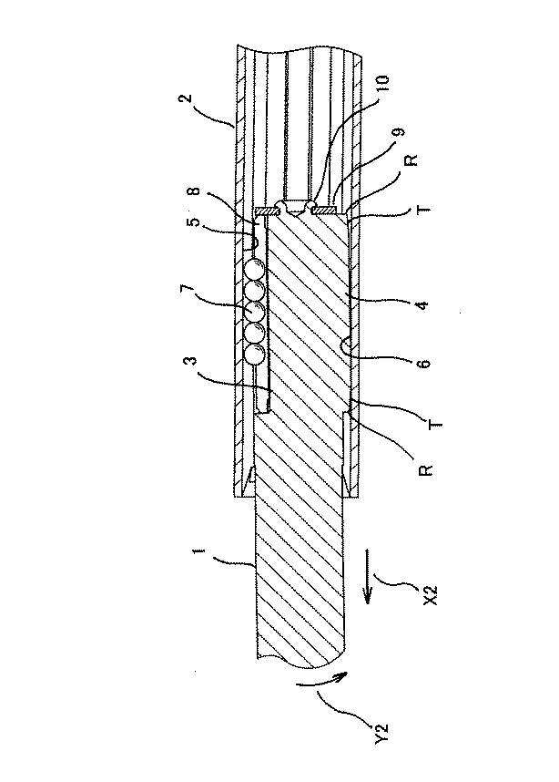
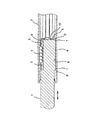
図7は、本発明の第2実施の形態に係る車両ステアリング用伸縮軸の横断面図である。なお、本実施の形態では、第1実施の形態と同様の構成には、同じ符号を付して、その説明を省略する。
FIG. 7 is a cross-sectional view of the telescopic shaft for vehicle steering according to the second embodiment of the present invention. In the present embodiment, the same components as those in the first embodiment are denoted by the same reference numerals, and the description thereof is omitted.
本実施の形態は、雄軸1の外周面に、固体潤滑膜11を形成したことに、その特徴がある。このように、雄軸1の外周面に固体潤滑膜11を形成することによって、トルク伝達部の軸方向凸条4と軸方向溝6との接触抵抗を低くすることが出来るため、総摺動荷重(転がりと滑りが両方作用している本発明の構造において、通常使用時に発生する摺動荷重を言う)を、第1実施の形態の場合に比べて低くすることが出来る。固体潤滑皮膜としては、二硫化モリブデンの紛体を樹脂中に分散混合し、それを吹き付けまたは浸漬後に焼き付けて皮膜を形成したものや、PTFE(四フッ化エチレン)を樹脂中に分散混合し、それを吹き付けまたは浸漬後に焼き付けて皮膜を形成したもの等が用いられる。また、固体潤滑皮膜のかわりに樹脂をコーティングしてもよい。その他の構成、作用、及び効果は、上述した第1実施の形態と同様である。
This embodiment is characterized in that the
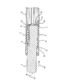
(第3実施の形態)
図8は、本発明の第3実施の形態に係る車両ステアリング用伸縮軸の横断面図である。なお、本実施の形態では、第1実施の形態と同様の構成には、同じ符号を付して、その説明を省略する。
(Third embodiment)
FIG. 8 is a cross-sectional view of the telescopic shaft for vehicle steering according to the third embodiment of the present invention. In the present embodiment, the same components as those in the first embodiment are denoted by the same reference numerals, and the description thereof is omitted.
本実施の形態では、雄軸1の外周面において周方向に120度間隔で等配した3個のそれぞれ略円弧状の断面形状を有する軸方向凸条4が延在して形成され、これに対応して雌軸2の内周面に雄軸1の3個の軸方向凸条4に対向する位置に3個の略円弧状の断面形状を有する軸方向溝6が延在して形成されている。摺動時には、軸方向凸条4と軸方向溝6とは、原則として互いに非接触であるが、高トルク伝達時には、互いに接触して、トルク伝達部を構成する。なお、軸方向凸条4及び軸方向溝6は、断面略円弧状、若しくはゴシックアーチ状であるが、その他の形状であってもよい。その他の構成、作用、及び効果は、上述した第1実施の形態と同様である。
In the present embodiment, three
但し、軸方向凸条4の外周面が略円弧形状であり、軸方向溝6の内周面も略円弧形状であることから、凹凸部(軸方向凸条6と軸方向溝6)の角部は、曲面形状Rに形成しなくても、その曲面形状(円弧形状)であることから、トルク伝達部である滑り摺動面の凹凸部(軸方向凸条6と軸方向溝6)は、スティック・スリップを生起することなく、スムーズにスライドすることができる。
However, since the outer peripheral surface of the
なお、本発明は、上述した実施の形態に限定されず、種々変形可能である。 In addition, this invention is not limited to embodiment mentioned above, A various deformation | transformation is possible.
1 雄軸
2 雌軸
3 軸方向溝
3a 平面状側面
3b 底面
4 軸方向凸条
5 軸方向溝
6 軸方向溝
6a 凸条
6b 立壁部
7 球状体(ボール、転動体)
8 弾性体
8a 球状体側接触部(伝達部材側接触部)
8b 溝面側接触部
8c 付勢部
8d 底部
9 ストッパープレート
10 加締め部
11 固体潤滑皮膜
100 メンバ
101 アッパブラケット
102 ロアブラケット
103 ステアリングコラム
104 ステアリングシャフト
105 ステアリングホイール
106 ユニバーサルジョイント
107 ロアステアリングシャフト部
108 操舵軸継手
109 ピニオンシャフト
110 フレーム
111 弾性体
112 ステアリングラック
120 アッパステアリングシャフト部
DESCRIPTION OF SYMBOLS 1
8
8b Groove surface
Claims (8)
前記雄軸の外周部と前記雌軸の内周部にそれぞれ設けられ、回転の際には互いに接触してトルクを伝達するトルク伝達部と、
前記トルク伝達部とは異なる位置の前記雄軸の外周部と前記雌軸の内周部の間に設けられ、前記雄軸と前記雌軸との軸方向相対移動の際には転動する転動体と、該転動体に径方向に隣接して配置され、該転動体を介して前記雄軸と前記雌軸とに予圧を与える弾性体とからなる予圧部と、を具備し、
前記トルク伝達部に於ける前記雄軸の外周部と前記雌軸の内周部とは、微少な所定間隔の隙間を維持しつつ、
前記トルク伝達部の前記雄軸は、曲面形状を有していることを特徴とする車両ステアリング用伸縮軸。 In the telescopic shaft for vehicle steering, which is incorporated in the steering shaft of the vehicle and the male shaft and the female shaft are slidably fitted to each other,
A torque transmitting portion provided on each of the outer peripheral portion of the male shaft and the inner peripheral portion of the female shaft, and in contact with each other at the time of rotation;
Roller that is provided between the outer peripheral part of the male shaft and the inner peripheral part of the female shaft at a position different from the torque transmission part, and rolls when the male shaft and the female shaft move relative to each other in the axial direction. A moving body, and a preload portion that is arranged adjacent to the rolling element in the radial direction and includes an elastic body that applies preload to the male shaft and the female shaft via the rolling body,
In the torque transmission portion, the outer peripheral portion of the male shaft and the inner peripheral portion of the female shaft are maintained with a small predetermined gap,
The telescopic shaft for vehicle steering, wherein the male shaft of the torque transmitting portion has a curved surface shape.
前記雄軸の外周部と前記雌軸の内周部にそれぞれ設けられ、回転の際には互いに接触してトルクを伝達するトルク伝達部と、
前記トルク伝達部とは異なる位置の前記雄軸の外周部と前記雌軸の内周部の間に設けられ、前記雄軸と前記雌軸との軸方向相対移動の際には転動する転動体と、該転動体に径方向に隣接して配置され、該転動体を介して前記雄軸と前記雌軸とに予圧を与える弾性体とからなる予圧部と、を具備し、
前記トルク伝達部に於ける前記雄軸の外周部と前記雌軸の内周部とは、微少な所定間隔の隙間を維持しつつ、
前記トルク伝達部の前記雄軸及び前記雌軸は、夫々、曲面形状を有していることを特徴とする車両ステアリング用伸縮軸。 In the telescopic shaft for vehicle steering, which is incorporated in the steering shaft of the vehicle and the male shaft and the female shaft are slidably fitted to each other,
A torque transmitting portion provided on each of the outer peripheral portion of the male shaft and the inner peripheral portion of the female shaft, and in contact with each other at the time of rotation;
Roller that is provided between the outer peripheral part of the male shaft and the inner peripheral part of the female shaft at a position different from the torque transmission part, and rolls when the male shaft and the female shaft move relative to each other in the axial direction. A moving body, and a preload portion that is arranged adjacent to the rolling element in the radial direction and includes an elastic body that applies preload to the male shaft and the female shaft via the rolling body,
In the torque transmission portion, the outer peripheral portion of the male shaft and the inner peripheral portion of the female shaft are maintained with a small predetermined gap,
The telescopic shaft for vehicle steering, wherein each of the male shaft and the female shaft of the torque transmitting portion has a curved surface shape.
前記トルク伝達部の前記雌軸の軸方向溝は、二つの軸方向溝の間に形成される凸条と、軸方向溝の端側の立壁部とで、その角部が曲面により形成してあることを特徴とする請求項6に記載の車両ステアリング用伸縮軸。 The axial ridge of the male shaft of the torque transmitting portion has an end portion that is tapered and a corner portion that is formed by a curved surface.
The axial groove of the female shaft of the torque transmission part is formed by a convex line formed between two axial grooves and a standing wall part on the end side of the axial groove, and the corner part is formed by a curved surface. The telescopic shaft for vehicle steering according to claim 6, wherein the telescopic shaft is provided.
Priority Applications (1)
| Application Number | Priority Date | Filing Date | Title |
|---|---|---|---|
| JP2004115785A JP4428117B2 (en) | 2004-04-09 | 2004-04-09 | Telescopic shaft for vehicle steering |
Applications Claiming Priority (1)
| Application Number | Priority Date | Filing Date | Title |
|---|---|---|---|
| JP2004115785A JP4428117B2 (en) | 2004-04-09 | 2004-04-09 | Telescopic shaft for vehicle steering |
Publications (2)
| Publication Number | Publication Date |
|---|---|
| JP2005297723A true JP2005297723A (en) | 2005-10-27 |
| JP4428117B2 JP4428117B2 (en) | 2010-03-10 |
Family
ID=35329799
Family Applications (1)
| Application Number | Title | Priority Date | Filing Date |
|---|---|---|---|
| JP2004115785A Expired - Lifetime JP4428117B2 (en) | 2004-04-09 | 2004-04-09 | Telescopic shaft for vehicle steering |
Country Status (1)
| Country | Link |
|---|---|
| JP (1) | JP4428117B2 (en) |
Cited By (8)
| Publication number | Priority date | Publication date | Assignee | Title |
|---|---|---|---|---|
| JP2008008331A (en) * | 2006-06-27 | 2008-01-17 | Jtekt Corp | Telescopic shaft and vehicle steering device |
| WO2008035705A1 (en) * | 2006-09-22 | 2008-03-27 | Omron Corporation | Rotation support mechanism and portable terminal |
| JP2011173464A (en) * | 2010-02-23 | 2011-09-08 | Jtekt Corp | Method for manufacturing spline telescopic shaft, spline telescopic shaft, and telescopic shaft for vehicle steering |
| JP2013249884A (en) * | 2012-05-31 | 2013-12-12 | Jtekt Corp | Spline telescopic shaft |
| JP2013252860A (en) * | 2013-08-27 | 2013-12-19 | Nsk Ltd | Method of manufacturing impact absorbing steering shaft |
| CN109296639A (en) * | 2018-12-06 | 2019-02-01 | 株洲易力达机电有限公司 | Novel sliding vice president at |
| CN111520416A (en) * | 2020-05-07 | 2020-08-11 | 豫北凯斯特隆(新乡)汽车科技有限公司 | Sliding pair structure of automobile steering intermediate shaft |
| KR102208239B1 (en) * | 2019-07-26 | 2021-01-28 | 남양넥스모 주식회사 | Intermediate shaft |
-
2004
- 2004-04-09 JP JP2004115785A patent/JP4428117B2/en not_active Expired - Lifetime
Cited By (9)
| Publication number | Priority date | Publication date | Assignee | Title |
|---|---|---|---|---|
| JP2008008331A (en) * | 2006-06-27 | 2008-01-17 | Jtekt Corp | Telescopic shaft and vehicle steering device |
| WO2008035705A1 (en) * | 2006-09-22 | 2008-03-27 | Omron Corporation | Rotation support mechanism and portable terminal |
| JP2011173464A (en) * | 2010-02-23 | 2011-09-08 | Jtekt Corp | Method for manufacturing spline telescopic shaft, spline telescopic shaft, and telescopic shaft for vehicle steering |
| JP2013249884A (en) * | 2012-05-31 | 2013-12-12 | Jtekt Corp | Spline telescopic shaft |
| JP2013252860A (en) * | 2013-08-27 | 2013-12-19 | Nsk Ltd | Method of manufacturing impact absorbing steering shaft |
| CN109296639A (en) * | 2018-12-06 | 2019-02-01 | 株洲易力达机电有限公司 | Novel sliding vice president at |
| KR102208239B1 (en) * | 2019-07-26 | 2021-01-28 | 남양넥스모 주식회사 | Intermediate shaft |
| CN111520416A (en) * | 2020-05-07 | 2020-08-11 | 豫北凯斯特隆(新乡)汽车科技有限公司 | Sliding pair structure of automobile steering intermediate shaft |
| CN111520416B (en) * | 2020-05-07 | 2024-05-28 | 豫北凯斯特隆(新乡)汽车科技有限公司 | Sliding pair structure of steering intermediate shaft of automobile |
Also Published As
| Publication number | Publication date |
|---|---|
| JP4428117B2 (en) | 2010-03-10 |
Similar Documents
| Publication | Publication Date | Title |
|---|---|---|
| JP3797304B2 (en) | Telescopic shaft for vehicle steering | |
| JP4419841B2 (en) | Telescopic shaft for vehicle steering | |
| JP4770193B2 (en) | Telescopic shaft for vehicle steering | |
| JP4696916B2 (en) | Telescopic shaft for vehicle steering | |
| US7481130B2 (en) | Vehicle steering telescopic shaft | |
| EP1553005A1 (en) | Extendable vehicle steering shaft | |
| EP1705394A1 (en) | Telescopic shaft for vehicle steering | |
| WO2004056638A1 (en) | Telescopic shaft for motor vehicle steering | |
| US8435124B2 (en) | Variable length steering spindle | |
| JP4428117B2 (en) | Telescopic shaft for vehicle steering | |
| JP2009197818A (en) | Telescopic shaft and steering device equipped with telescopic shaft | |
| JP2003247560A (en) | Telescopic shaft for vehicle steering | |
| JP2003291827A (en) | Telescopic shaft for vehicle steering | |
| JP2005306216A (en) | Vehicle steering system | |
| JP2005299779A (en) | Telescopic shaft for vehicle steering | |
| JP4586983B2 (en) | Telescopic shaft for vehicle steering | |
| JP2005324599A (en) | Telescopic shaft for vehicle steering | |
| JP2005349964A (en) | Telescopic shaft for vehicle steering | |
| JP2005231625A (en) | Telescopic shaft for vehicle steering | |
| JP2007315516A (en) | Telescopic shaft for vehicle steering | |
| JP2005313693A (en) | Telescopic shaft for vehicle steering | |
| JP2011073543A5 (en) | ||
| JP2011073543A (en) | Telescopic shaft for vehicle steering | |
| JP2003118594A (en) | Telescopic shaft for vehicle steering | |
| JP2005313691A (en) | Telescopic shaft for vehicle steering |
Legal Events
| Date | Code | Title | Description |
|---|---|---|---|
| A711 | Notification of change in applicant |
Free format text: JAPANESE INTERMEDIATE CODE: A711 Effective date: 20050711 |
|
| A621 | Written request for application examination |
Free format text: JAPANESE INTERMEDIATE CODE: A621 Effective date: 20070221 |
|
| A131 | Notification of reasons for refusal |
Free format text: JAPANESE INTERMEDIATE CODE: A131 Effective date: 20090407 |
|
| A521 | Request for written amendment filed |
Free format text: JAPANESE INTERMEDIATE CODE: A523 Effective date: 20090608 |
|
| TRDD | Decision of grant or rejection written | ||
| A01 | Written decision to grant a patent or to grant a registration (utility model) |
Free format text: JAPANESE INTERMEDIATE CODE: A01 Effective date: 20091124 |
|
| A01 | Written decision to grant a patent or to grant a registration (utility model) |
Free format text: JAPANESE INTERMEDIATE CODE: A01 |
|
| FPAY | Renewal fee payment (event date is renewal date of database) |
Free format text: PAYMENT UNTIL: 20121225 Year of fee payment: 3 |
|
| R150 | Certificate of patent or registration of utility model |
Ref document number: 4428117 Country of ref document: JP Free format text: JAPANESE INTERMEDIATE CODE: R150 Free format text: JAPANESE INTERMEDIATE CODE: R150 |
|
| A61 | First payment of annual fees (during grant procedure) |
Free format text: JAPANESE INTERMEDIATE CODE: A61 Effective date: 20091207 |
|
| FPAY | Renewal fee payment (event date is renewal date of database) |
Free format text: PAYMENT UNTIL: 20121225 Year of fee payment: 3 |
|
| FPAY | Renewal fee payment (event date is renewal date of database) |
Free format text: PAYMENT UNTIL: 20131225 Year of fee payment: 4 |
|
| EXPY | Cancellation because of completion of term |