JP2005231625A - Extendable shaft for vehicle steering - Google Patents
Extendable shaft for vehicle steering Download PDFInfo
- Publication number
- JP2005231625A JP2005231625A JP2005129888A JP2005129888A JP2005231625A JP 2005231625 A JP2005231625 A JP 2005231625A JP 2005129888 A JP2005129888 A JP 2005129888A JP 2005129888 A JP2005129888 A JP 2005129888A JP 2005231625 A JP2005231625 A JP 2005231625A
- Authority
- JP
- Japan
- Prior art keywords
- shaft
- vehicle steering
- female
- male
- axial
- Prior art date
- Legal status (The legal status is an assumption and is not a legal conclusion. Google has not performed a legal analysis and makes no representation as to the accuracy of the status listed.)
- Pending
Links
Images


Classifications
-
- F—MECHANICAL ENGINEERING; LIGHTING; HEATING; WEAPONS; BLASTING
- F16—ENGINEERING ELEMENTS AND UNITS; GENERAL MEASURES FOR PRODUCING AND MAINTAINING EFFECTIVE FUNCTIONING OF MACHINES OR INSTALLATIONS; THERMAL INSULATION IN GENERAL
- F16C—SHAFTS; FLEXIBLE SHAFTS; ELEMENTS OR CRANKSHAFT MECHANISMS; ROTARY BODIES OTHER THAN GEARING ELEMENTS; BEARINGS
- F16C29/00—Bearings for parts moving only linearly
- F16C29/12—Arrangements for adjusting play
- F16C29/123—Arrangements for adjusting play using elastic means
-
- F—MECHANICAL ENGINEERING; LIGHTING; HEATING; WEAPONS; BLASTING
- F16—ENGINEERING ELEMENTS AND UNITS; GENERAL MEASURES FOR PRODUCING AND MAINTAINING EFFECTIVE FUNCTIONING OF MACHINES OR INSTALLATIONS; THERMAL INSULATION IN GENERAL
- F16C—SHAFTS; FLEXIBLE SHAFTS; ELEMENTS OR CRANKSHAFT MECHANISMS; ROTARY BODIES OTHER THAN GEARING ELEMENTS; BEARINGS
- F16C29/00—Bearings for parts moving only linearly
- F16C29/007—Hybrid linear bearings, i.e. including more than one bearing type, e.g. sliding contact bearings as well as rolling contact bearings
-
- F—MECHANICAL ENGINEERING; LIGHTING; HEATING; WEAPONS; BLASTING
- F16—ENGINEERING ELEMENTS AND UNITS; GENERAL MEASURES FOR PRODUCING AND MAINTAINING EFFECTIVE FUNCTIONING OF MACHINES OR INSTALLATIONS; THERMAL INSULATION IN GENERAL
- F16C—SHAFTS; FLEXIBLE SHAFTS; ELEMENTS OR CRANKSHAFT MECHANISMS; ROTARY BODIES OTHER THAN GEARING ELEMENTS; BEARINGS
- F16C2326/00—Articles relating to transporting
- F16C2326/20—Land vehicles
- F16C2326/24—Steering systems, e.g. steering rods or columns
-
- F—MECHANICAL ENGINEERING; LIGHTING; HEATING; WEAPONS; BLASTING
- F16—ENGINEERING ELEMENTS AND UNITS; GENERAL MEASURES FOR PRODUCING AND MAINTAINING EFFECTIVE FUNCTIONING OF MACHINES OR INSTALLATIONS; THERMAL INSULATION IN GENERAL
- F16C—SHAFTS; FLEXIBLE SHAFTS; ELEMENTS OR CRANKSHAFT MECHANISMS; ROTARY BODIES OTHER THAN GEARING ELEMENTS; BEARINGS
- F16C29/00—Bearings for parts moving only linearly
- F16C29/04—Ball or roller bearings
-
- F—MECHANICAL ENGINEERING; LIGHTING; HEATING; WEAPONS; BLASTING
- F16—ENGINEERING ELEMENTS AND UNITS; GENERAL MEASURES FOR PRODUCING AND MAINTAINING EFFECTIVE FUNCTIONING OF MACHINES OR INSTALLATIONS; THERMAL INSULATION IN GENERAL
- F16C—SHAFTS; FLEXIBLE SHAFTS; ELEMENTS OR CRANKSHAFT MECHANISMS; ROTARY BODIES OTHER THAN GEARING ELEMENTS; BEARINGS
- F16C3/00—Shafts; Axles; Cranks; Eccentrics
- F16C3/02—Shafts; Axles
- F16C3/03—Shafts; Axles telescopic
- F16C3/035—Shafts; Axles telescopic with built-in bearings
Landscapes
- Engineering & Computer Science (AREA)
- General Engineering & Computer Science (AREA)
- Mechanical Engineering (AREA)
- Steering Controls (AREA)
Abstract
Description
本発明は、車両ステアリング用伸縮軸に関する。 The present invention relates to a telescopic shaft for vehicle steering.
従来、自動車の操舵機構部では、自動車が走行する際に発生する軸方向の変位を吸収し、ステアリングホイール上にその変位や振動を伝えないために雄軸と雌軸とをスプライン嵌合した伸縮軸を操舵機構部の一部に使用している。伸縮軸にはスプライン部のガタ音を低減することと、ステアリングホイール上のガタ感を低減することと、軸方向摺動時における摺動抵抗を低減することが要求される。 Conventionally, the steering mechanism part of an automobile absorbs the displacement in the axial direction that occurs when the automobile travels, and the expansion and contraction is a spline fit between the male shaft and the female shaft in order not to transmit the displacement or vibration on the steering wheel. The shaft is used as part of the steering mechanism. The telescopic shaft is required to reduce the rattling noise of the spline part, to reduce the rattling on the steering wheel, and to reduce the sliding resistance when sliding in the axial direction.
このようなことから、伸縮軸の雄軸のスプライン部に対して、ナイロン膜をコーティングし、さらに摺動部にグリースを塗布し、金属騒音、金属打音等を吸収または緩和すると共に摺動抵抗の低減と回転方向ガタの低減を行ってきた。この場合、ナイロン膜を形成する工程としてはシャフトの洗浄→プライマー塗布→加熱→ナイロン粉末コート→粗切削→仕上げ切削→雌軸との選択嵌合が行われている。最終の切削加工は、既に加工済みの雌軸の精度に合わせてダイスを選択して加工を行っている。 Because of this, the nylon spline part of the telescopic shaft is coated with nylon film, and grease is applied to the sliding part to absorb or reduce metal noise, metal hitting sound, etc., and sliding resistance Have been reduced and the play in the rotational direction has been reduced. In this case, as a process of forming the nylon film, cleaning of the shaft → primer application → heating → nylon powder coating → rough cutting → finish cutting → selective fitting with the female shaft is performed. The final cutting process is performed by selecting a die in accordance with the accuracy of the already processed female shaft.
また、特開2001−50293号公報(特許文献1参照。)では、内側シャフトの外周部と外側シャフトの内周部とに設けられた溝部に、内側シャフトの溝部とボールとの間に弾性体を介してボールを配置して、軸方向の移動の際にはボールを転動させることによって雄軸と雌軸の摺動荷重を減少させると共に、回転の際にはボールを拘束してトルクを伝達する車両ステアリング用伸縮軸が開示されている。さらに、上記公報にはボールの破損時でもトルクの伝達を可能とするために、ある遊びを持った組合せ断面を有する雄溝および雌溝が内側シャフトおよび外側シャフトに設けられていることが開示されている。 In Japanese Patent Laid-Open No. 2001-50293 (see Patent Document 1), an elastic body is provided between a groove portion of the inner shaft and a ball in a groove portion provided on the outer peripheral portion of the inner shaft and the inner peripheral portion of the outer shaft. The ball is arranged via a pin, and the ball is rolled during the axial movement to reduce the sliding load of the male shaft and the female shaft. A telescopic shaft for transmitting a vehicle steering is disclosed. Further, the above publication discloses that a male groove and a female groove having a combined cross section with a certain play are provided on the inner shaft and the outer shaft in order to enable transmission of torque even when the ball is broken. ing.
しかしながら、前者では伸縮軸の摺動荷重を最小に抑えつつガタをも最小に抑えることが必要である為、最終の切削加工ではオーバーピン径サイズが数ミクロンづつ異なるダイスを雌軸にあわせて選び出し加工することを余儀なくされ、加工コストの高騰を招来してしまう。また、使用経過によりナイロン膜の摩耗が進展して回転方向ガタが大きくなる。 However, in the former, it is necessary to minimize the sliding load of the telescopic shaft while minimizing the backlash, so in the final cutting process, dies with different overpin diameter sizes of several microns are selected according to the female shaft. It will be forced to process, and the processing cost will rise. Further, wear of the nylon film progresses with the progress of use, and the rotational play is increased.
また、エンジンルーム内の高温にさらされる条件下では、ナイロン膜は体積変化し、摺動抵抗が著しく高くなったり、磨耗が著しく促進されたりするため、回転方向ガタが大きくなる。したがって、自動車用操舵軸に使用される伸縮軸において、回転方向ガタによる異音の発生と操舵感の悪化を長期にわたって抑制できる構造を簡単且つ安価に提供したいといった要望がある。 Further, under conditions where the engine room is exposed to high temperatures, the nylon membrane changes in volume, and the sliding resistance becomes remarkably high and wear is remarkably promoted, so that the backlash in the rotational direction becomes large. Therefore, there is a demand to provide a structure that can suppress the generation of abnormal noise due to backlash in the rotational direction and the deterioration of the steering feeling over a long period of time in a telescopic shaft used for a steering shaft for an automobile.
また、後者の特開2001−50293号公報に開示された車両ステアリング用伸縮軸では、通常使用時は、複数のボールが転がりによる伸縮動作とトルク伝達を行っている。このため、構造上入力トルクに耐えるだけのボール数を設けなければならず、車両ステアリング用伸縮軸としての小型化が困難であると共に、車両衝突時に十分なコラプスストロークをとることが難しいという構造上の欠点もある。さらに、ボールのみで構成しているため摺動荷重が変動するといった車両ステアリング用伸縮軸としては好ましくない特性が現れるといった問題もある。 Further, in the latter telescopic shaft for vehicle steering disclosed in the latter Japanese Patent Application Laid-Open No. 2001-50293, during normal use, a plurality of balls perform expansion and contraction operations and torque transmission by rolling. For this reason, the number of balls that can withstand the input torque must be provided structurally, and it is difficult to reduce the size of the telescopic shaft for vehicle steering, and it is difficult to take a sufficient collapse stroke at the time of a vehicle collision. There are also disadvantages. Furthermore, since it is composed only of balls, there is a problem that undesirable characteristics appear as a telescopic shaft for vehicle steering in which the sliding load fluctuates.
本発明は、上述したような事情に鑑みてなされたものであって、安定した摺動荷重を実現すると共に、回転方向ガタ付きを確実に防止して、高剛性の状態でトルクを伝達できる車両ステアリング用伸縮軸を提供することを目的とする。 The present invention has been made in view of the above-described circumstances, and can realize a stable sliding load, reliably prevent backlash in the rotational direction, and transmit torque in a highly rigid state. An object is to provide a telescopic shaft for steering.
上記の目的を達成するため、本発明に係る車両ステアリング用伸縮軸は、車両のステアリングシャフトに組込み、雄軸と雌軸を回転不能に且つ摺動自在に嵌合した車両ステアリング用伸縮軸において、
前記雄軸の外周部と前記雌軸の内周部にそれぞれ設けられ、互いに接触して回転の際にはトルクを伝達するトルク伝達部と、
前記トルク伝達部とは異なる位置の前記雄軸の外周部と前記雌軸の内周部の間に設けられ、前記雄軸と前記雌軸との軸方向相対移動の際には転動する転動体と、該転動体に径方向に隣接して配置され、該転動体を介して前記雄軸と前記雌軸とに予圧を与える弾性体とからなる予圧部とを具備してなることを特徴とする。
To achieve the above object, a telescopic shaft for vehicle steering according to the present invention is incorporated in a steering shaft of a vehicle, and a telescopic shaft for vehicle steering in which a male shaft and a female shaft are non-rotatably and slidably fitted.
A torque transmitting portion provided on each of the outer peripheral portion of the male shaft and the inner peripheral portion of the female shaft, and contacting each other to transmit torque when rotating;
Roller that is provided between the outer peripheral part of the male shaft and the inner peripheral part of the female shaft at a position different from the torque transmission part, and rolls when the male shaft and the female shaft move relative to each other in the axial direction. A moving body, and a preload portion that is disposed adjacent to the rolling element in a radial direction and includes an elastic body that preloads the male shaft and the female shaft via the rolling body. And
また、本発明に係る車両ステアリング用伸縮軸では、前記トルク伝達部は、常時互いに摺動可能に接触していることが好ましい。 Moreover, in the telescopic shaft for vehicle steering according to the present invention, it is preferable that the torque transmission parts are always in slidable contact with each other.
また、本発明に係る車両ステアリング用伸縮軸では、前記トルク伝達部は、前記雄軸の外周面に形成された断面形状が略円弧状の軸方向凸条と前記雌軸の内周面に形成された断面形状が略円弧状の軸方向溝から構成されていることが好ましい。 Moreover, in the telescopic shaft for vehicle steering according to the present invention, the torque transmitting portion is formed on the axial ridge having a substantially arc shape in cross section formed on the outer peripheral surface of the male shaft and the inner peripheral surface of the female shaft. It is preferable that the formed cross-sectional shape is constituted by a substantially arc-shaped axial groove.
また、本発明に係る車両ステアリング用伸縮軸では、前記トルク伝達部は、互いに軸方向に連続して接触していることが好ましい。 Moreover, in the telescopic shaft for vehicle steering according to the present invention, it is preferable that the torque transmission parts are in continuous contact with each other in the axial direction.
また、本発明に係る車両ステアリング用伸縮軸では、前記トルク伝達部は、前記雄軸の外周面と前記雌軸の内周面に形成されたスプライン嵌合部またはセレーション嵌合部からなることが好ましい。 Further, in the telescopic shaft for vehicle steering according to the present invention, the torque transmitting portion may comprise a spline fitting portion or a serration fitting portion formed on the outer peripheral surface of the male shaft and the inner peripheral surface of the female shaft. preferable.
また、本発明に係る車両ステアリング用伸縮軸では、前記予圧部は、前記雄軸の外周面に設けられた第1の軸方向溝と、該第1の軸方向溝に対向して前記雌軸の内周面に設けられた第2の軸方向溝とを有し、
前記転動体と前記弾性体は、該第1および第2の軸方向溝間に配置されていることが好ましい
また、本発明に係る車両ステアリング用伸縮軸では、前記予圧部は、前記雄軸と前記雌軸との間に複数配置され、前記トルク伝達部は、隣り合う前記予圧部の間に複数配置されていることが好ましい。
In the telescopic shaft for vehicle steering according to the present invention, the preload portion includes a first axial groove provided on an outer peripheral surface of the male shaft, and the female shaft facing the first axial groove. A second axial groove provided on the inner peripheral surface of
Preferably, the rolling element and the elastic body are disposed between the first and second axial grooves. In the vehicle steering telescopic shaft according to the present invention, the preload portion includes the male shaft. It is preferable that a plurality of torque transmission parts are arranged between the female shafts, and a plurality of the torque transmission parts are arranged between the adjacent preloading parts.
また、本発明に係る車両ステアリング用伸縮軸では、前記予圧部は、周方向に180度間隔で配置され、前記予圧部の間に、それぞれ前記トルク伝達部を配置していることが好ましい。 In the telescopic shaft for vehicle steering according to the present invention, it is preferable that the preload portions are arranged at intervals of 180 degrees in the circumferential direction, and the torque transmission portions are arranged between the preload portions.
また、本発明に係る車両ステアリング用伸縮軸では、前記予圧部は、周方向に120度間隔で等配して配置され、前記予圧部の間に、それぞれ前記トルク伝達部を配置していることが好ましい。 Moreover, in the telescopic shaft for vehicle steering according to the present invention, the preload portions are arranged at equal intervals of 120 degrees in the circumferential direction, and the torque transmission portions are respectively disposed between the preload portions. Is preferred.
また、本発明に係る車両ステアリング用伸縮軸では、前記トルク伝達部は、前記予圧部の間に周方向中央部にそれぞれ配置されていることが好ましい。 Moreover, in the telescopic shaft for vehicle steering according to the present invention, it is preferable that the torque transmitting portion is disposed at a central portion in the circumferential direction between the preload portions.
また、本発明に係る車両ステアリング用伸縮軸では、前記転動体は、少なくとも1つの球状体からなることが好ましい。
また、本発明に係る車両ステアリング用伸縮軸では、前記弾性体は、板バネからなることが好ましい。
また、本発明に係る車両ステアリング用伸縮軸では、前記雄軸の外周部または前記雌軸の内周部に固体潤滑皮膜が形成されていることが好ましい。
In the telescopic shaft for vehicle steering according to the present invention, it is preferable that the rolling element is composed of at least one spherical body.
In the telescopic shaft for vehicle steering according to the present invention, it is preferable that the elastic body is a leaf spring.
In the telescopic shaft for vehicle steering according to the present invention, it is preferable that a solid lubricating film is formed on the outer peripheral portion of the male shaft or the inner peripheral portion of the female shaft.
以下、本発明の実施の形態に係る車両ステアリング用伸縮軸を図面を参照しつつ説明する。 Hereinafter, a telescopic shaft for vehicle steering according to an embodiment of the present invention will be described with reference to the drawings.
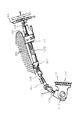
図1は、本発明の実施の形態に係る車両ステアリング用伸縮軸を適用した自動車の操舵機構部の側面図である。 FIG. 1 is a side view of a steering mechanism portion of an automobile to which a vehicle steering telescopic shaft according to an embodiment of the present invention is applied.
図1において、車体側のメンバ100にアッパブラケット101とロアブラケット102とを介して取り付けられたアッパステアリングシャフト部120(ステアリングコラム103と、ステアリングコラム103に回転自在に保持されたスアリングシャフト104を含む)と、ステアリングシャフト104の上端に装着されたステアリングホイール105と、ステアリングシャフト104の下端にユニバーサルジョイント106を介して連結されたロアステアリングシャフト部107と、ロアステアリングシャフト部107に操舵軸継手108を介して連結されたピニオンシャフト109と、ピニオンシャフト109に連結されて車体の別のフレーム110に弾性体111を介して固定されたステアリングラック112とから操舵機構部が構成されている。
In FIG. 1, an upper steering shaft portion 120 (a
ここで、アッパステアリングシャフト部120とロアステアリングシャフト部107が本発明の実施の形態に係る車両ステアリング用伸縮軸(以後、伸縮軸と記す)を用いている。ロアステアリングシャフト部107は、雄軸と雌軸とを嵌合したものであるが、このようなロアステアリングシャフト部107には自動車が走行する際に発生する軸方向の変位を吸収し、ステアリングホイール105上にその変位や振動を伝えない性能が要求される。このような性能は、車体がサブフレーム構造となっていて、操舵機構上部を固定するメンバ100とステアリングラック112が固定されているフレーム110が別体となっておりその間がゴムなどの弾性体111を介して締結固定されている構造の場合に要求される。また、その他のケースとして操舵軸継手108をピニオンシャフト109に締結する際に作業者が、伸縮軸をいったん縮めてからピニオンシャフト109に嵌合させ締結させるため伸縮機能が必要とされる場合がある。さらに、操舵機構の上部にあるアッパステアリングシャフト部120も、雄軸と雌軸とを嵌合したものであるが、このようなアッパステアリングシャフト部120には、運転者が自動車を運転するのに最適なポジションを得るためにステアリングホイール105の位置を軸方向に移動し、その位置を調整する機能が要求されるため、軸方向に伸縮する機能が要求される。前述のすべての場合において、伸縮軸には嵌合部のガタ音を低減することと、ステアリングホイール105上のガタ感を低減することと、軸方向摺動時における摺動抵抗を低減することが要求される。
Here, the upper
(第1実施の形態)
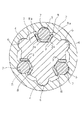
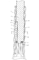
図2は、本発明の第1実施の形態に係る車両ステアリング用伸縮軸の断面図であり、図3は、図2のX−X線に沿った断面図である。図4は、第1実施の形態に係る車両ステアリング用伸縮軸のストロークと摺動荷重の関係を示すグラフである。
(First embodiment)
2 is a cross-sectional view of the telescopic shaft for vehicle steering according to the first embodiment of the present invention, and FIG. 3 is a cross-sectional view taken along line XX of FIG. FIG. 4 is a graph showing the relationship between the stroke of the telescopic shaft for vehicle steering and the sliding load according to the first embodiment.
図2、図3に示すように、車両ステアリング用伸縮軸(以後、伸縮軸と記す)は、相互に回転不能に且つ摺動自在に嵌合した雄軸1と雌軸2とからなる。
As shown in FIGS. 2 and 3, the telescopic shaft for vehicle steering (hereinafter referred to as the telescopic shaft) includes a
本第1実施の形態では、雄軸1の外周面において周方向に120度間隔で等配した3個のそれぞれ略円弧状の断面形状を有する軸方向凸条4が延在して形成され、これに対応して雌軸2の内周面に雄軸1の3個の軸方向凸条4に対向する位置に3個の略円弧状の断面形状を有する軸方向溝6が延在して形成され、軸方向凸条4と軸方向溝6とは接触してトルク伝達部を形成している。
In the first embodiment, three
雄軸1の外周部において3個の軸方向凸条4のそれぞれ隣合うものの間には略U字形状の第1の軸方向溝3(以後、軸方向溝3と記す)が延在して形成してある。雌軸2の内周面には雄軸1の軸方向溝3と対向して3個の略円弧状の断面形状を有する第2の軸方向溝5(以後、軸方向溝5と記す)が延在して形成されている。雄軸1の軸方向溝3と雌軸2の軸方向溝5との間には予圧用の波型形状の弾性体8を介して、転動体7が介装されている。転動体7は雄軸1と雌軸2との軸方向相対移動の際には転動し、回転の際には弾性体8に拘束されているためガタを感じさせない構造となっている。
A substantially U-shaped first axial groove 3 (hereinafter referred to as an axial groove 3) extends between adjacent ones of the three
弾性体8は、その両側の平坦部8a、8aで軸方向溝3の両側の壁部3a、3aに圧接してあり、弾性体8全体が周方向に移動できないように拘束している。弾性体8は転動体7に予圧を与えると共に、転動体7と軸方向凸条4を雌軸2に対してガタ付のない程度に予圧する働きをする。
The
雄軸1が雌軸2に挿入される側の端部には、弾性体8を係止して軸方向に固定するストッパープレート9が加締め部10により雄軸1に加締められている。このストッパープレート9は転動体7が雄軸1の軸方向溝3から外れないようにする働きもしている。このようにして第1実施の形態の車両ステアリング用伸縮軸が構成されている。
A
本第1実施の形態の伸縮軸は、このような構造であるので、予圧部の存在によりそれぞれのトルク伝達部において雄軸1と雌軸2は常時摺動可能に接触しており、雄軸1と雌軸2との軸方向の相対移動の際には互いに摺動し、且つ転動体7は転動することが出来る。
Since the telescopic shaft of the first embodiment has such a structure, the
図4は、本第1実施の形態に係る車両ステアリング用伸縮軸のストロークと摺動荷重の関係を示すグラフである。図4では、ボール転がりのみの場合、滑りのみの場合および本発明の場合のストロークと摺動荷重の関係を比較して示している。これにより、本発明実施の形態に係る車両ステアリング用伸縮軸が、低い摺動荷重であり、摺動荷重の変動を抑制でき、且つ滑らかな摺動特性を有していることが分かる。 FIG. 4 is a graph showing the relationship between the stroke of the telescopic shaft for vehicle steering and the sliding load according to the first embodiment. FIG. 4 shows a comparison of the relationship between the stroke and the sliding load in the case of only ball rolling, the case of only sliding, and the case of the present invention. Thus, it can be seen that the vehicle steering telescopic shaft according to the embodiment of the present invention has a low sliding load, can suppress fluctuations in the sliding load, and has smooth sliding characteristics.
なお、軸方向凸条4の曲率と軸方向溝6の曲率は異なっており、軸方向凸条4と軸方向溝6は接触の際に軸方向に連続して接触するようにそれぞれ形成されていても良い。また、雄軸に形成されている軸方向凸条4が雌軸側に、雌軸に形成されている軸方向溝6が雄軸側に形成されていても本第1実施の形態と同様の作用、効果が得られる。また、軸方向溝5の曲率と転動体7の曲率が異なっていて、両者は点接触するように形成されていても良い。また、転動体7は球状体であっても良い。さらに、弾性体8は板バネであっても良い。また、摺動面および転動面にグリースを塗布することによりさらに低い摺動荷重を得ることが出来る。
In addition, the curvature of the
このように構成された本第1実施の形態の伸縮軸は、以下の点が従来技術に比べ優れている。 The telescopic shaft of the first embodiment configured as described above is superior to the prior art in the following points.
従来技術のように摺動面が純粋な滑りによるものであれば、ガタつき防止のための予圧荷重をある程度の荷重で留めておくことしかできなかった。それは、摺動荷重は、摩擦係数に予圧荷重を乗じたものであり、ガタつき防止や伸縮軸の剛性を向上させたいと願って予圧荷重を上げてしまうと摺動荷重が増大してしまうという悪循環に陥ってしまうためである。 If the sliding surface is purely sliding as in the prior art, the preload load for preventing rattling could only be kept at a certain level. That is, the sliding load is the friction coefficient multiplied by the preload, and if the preload is increased to prevent rattling and improve the rigidity of the telescopic shaft, the sliding load will increase. This is because it falls into a vicious circle.
その点、本実施の形態では、予圧部は軸方向の相対移動の際には、転動体7の転動機構を採用しているため、著しい摺動荷重の増大を招くことなく予圧荷重を上げることができる。これにより、従来なし得なかったガタつきの防止と剛性の向上を摺動荷重の増大を招くことなく達成することができる。
In this respect, in the present embodiment, the preload portion employs a rolling mechanism of the rolling
そして、トルク伝達時には、トルク伝達部の軸方向凸条4が軸方向溝6に接触していることによってトルク伝達の役割を果たし、予圧部では板バネ8が弾性変形して球状体7を雄軸1と雌軸2の間で周方向に拘束してガタつきを防止することが出来る。
At the time of torque transmission, the
例えば、雄軸1からトルクが入力された場合、初期の段階では、弾性体8の予圧が加わっているため、ガタ付を防止する。
For example, when torque is input from the
さらにトルクが増大していくと、トルク伝達部の軸方向凸条4と軸方向溝6の側面が強く接触し、軸方向凸条4の方が球状体7より反力を強く受け、トルク伝達部が主にトルクを伝達する。そのため、本第1実施の形態では、雄軸1と雌軸2の回転方向ガタを確実に防止すると共に、高剛性の状態でトルクを伝達することができる。
As the torque further increases, the
断面形状が略円弧状の軸方向凸条4と軸方向溝6とは、主に軸方向に連続して接触してその荷重を受けるため、点接触で荷重を受ける転動体7よりも接触圧を低く抑えることができるなど、さまざまな効果がある。したがって、全列をボール転がり構造とした従来例に比べ下記の項目が優れている。
・摺動部での減衰能効果が、ボール転がり構造に比べて大きい。よって振動吸収性能が高い。
・同じトルクを伝達するならば、軸方向凸条4の方が接触圧を低く抑えることができるため、トルク伝達部の軸方向の長さを短くできスペースを有効に使うことができる。
・同じトルクを伝達するならば、軸方向凸条4の方が接触圧を低く抑えることができるため、熱処理等によって雌軸の軸方向溝表面を硬化させるための追加工程が不要である。
・部品点数を少なくすることができる。
・組立性をよくすることができる。
・組立コストを抑えることができる。
・トルクの伝達を主にトルク伝達部で担っているため、転動体7の数を少なくすることが出来、コラップスストロークを大きくとることが出来る。
Since the
・ The damping effect at the sliding part is larger than that of the ball rolling structure. Therefore, vibration absorption performance is high.
-If the same torque is transmitted, since the
-If the same torque is transmitted, since the
・ The number of parts can be reduced.
・ Assembly can be improved.
・ Assembly costs can be reduced.
-Since the torque transmission is mainly handled by the torque transmission part, the number of
転動体7を部分的に採用したという点では、全列がスプライン嵌合で且つ、全列が摺動する構造の従来例と比較して、下記の項目が優れている。
・摩擦抵抗が低いため、摺動荷重を低く抑えられる。
・予圧荷重を高くすることができ、長期にわたるガタつきの防止と高剛性が同時に得られる。
The following items are superior to the conventional example in which all the rows are spline fitted and all the rows slide in that the rolling
・ Sliding load can be kept low because of low frictional resistance.
・ Preload can be increased, and long-term rattling and high rigidity can be achieved at the same time.
(第2実施の形態)
図5は、本発明の第2実施の形態に係る車両ステアリング用伸縮軸の断面図であり、図6は、図5のX−X線に沿った断面図である。第1実施の形態と同様の構成には同じ符号を付し説明を省略する。
(Second Embodiment)
FIG. 5 is a cross-sectional view of the telescopic shaft for vehicle steering according to the second embodiment of the present invention, and FIG. 6 is a cross-sectional view taken along line XX of FIG. The same components as those in the first embodiment are denoted by the same reference numerals and description thereof is omitted.
本第2実施の形態が、第1実施の形態と異なるところは、雄軸1の外周面に固体潤滑皮膜11を形成していることにある。このように、雄軸1の外周面に固体潤滑膜11を形成することによって、トルク伝達部の軸方向凸条4と軸方向溝6との接触抵抗を低くすることが出来るため、総摺動荷重(転がりと滑りが両方作用している本発明の構造において、通常使用時に発生する摺動荷重を言う)を第1実施の形態の場合に比べて低くすることが出来る。
The second embodiment is different from the first embodiment in that a
そして、本第2実施の形態の場合も、第1実施の形態と同様の作用、効果が得られる。 Also in the case of the second embodiment, the same operation and effect as in the first embodiment can be obtained.
固体潤滑皮膜11としては、二酸化モリブデンの紛体を樹脂中に分散混合し、それを吹き付けまたは浸漬後に焼き付けて皮膜を形成したものや、PTFE(四フッ化エチレン)を樹脂中に分散混合し、それを吹き付けまたは浸漬後に焼き付けて皮膜を形成したもの等が用いられる。
As the
なお、本第2実施の形態では、固体潤滑皮膜11は雄軸1の外周面の全体にわたって形成されているが、雄軸1に形成されている3箇所の軸方向凸条4の外周面のみに設けても良い。これは、摺動荷重の主たる要因が、軸方向凸条4と軸方向溝6との接触よるものであり、この接触部の接触抵抗を低減することで軸方向の摺動抵抗を下げることが出来るからである。
In the second embodiment, the
また、摺動面及び転動面にグリースを塗布することによりさらに低い摺動荷重を得ることが出来る。また、軸方向凸条4の曲率と軸方向溝6の曲率は異なっており、軸方向凸条4と軸方向溝6は接触の際に軸方向に連続して接触するようにそれぞれ形成されていても良い。また、雄軸に形成されている軸方向凸条4が雌軸に側に、雌軸に形成されている軸方向溝6が雄軸側に形成されていても本願実施の形態と同様の作用、効果が得られる。また、軸方向溝5の曲率と転動体7の曲率が異なっていて、両者は点接触するように形成されていても良い。また、転動体7は球状体であっても良い。さらに、弾性体8は板バネであっても良い。
Further, a lower sliding load can be obtained by applying grease to the sliding surface and the rolling surface. Moreover, the curvature of the
(第3実施の形態)
図7は、本発明の第3実施の形態に係る車両ステアリング用伸縮軸の断面図であり、図8は、図7X−X線に沿った断面図である。第2実施の形態と同様の構成には同じ符号を付し説明を省略する。
(Third embodiment)
FIG. 7 is a cross-sectional view of the telescopic shaft for vehicle steering according to the third embodiment of the present invention, and FIG. 8 is a cross-sectional view taken along the line XX in FIG. The same components as those in the second embodiment are denoted by the same reference numerals, and description thereof is omitted.
本第3実施の形態が、第2実施の形態と異なるところは、雄軸1を中空構造(中空部13)として、車両ステアリング用伸縮軸全体の軽量化を図ったこと、また、雄軸1を中空構造にしたことによりストッパープレート12を雄軸1の中空部13に挿入後加締めているところにある。その他の構成、作用および効果は第2実施の形態と同様であり説明を省略する。
The third embodiment is different from the second embodiment in that the
なお、本第3実施の形態では、固体潤滑皮膜11は雄軸1の外周面の全体にわたって形成されているが、雄軸1に形成された3箇所の軸方向凸条4の外周面のみに設けても良い。なお、固体潤滑膜11は雌軸2の内周面側に形成されていても同様の作用、効果が得られる。
In the third embodiment, the
また、軸方向凸条4の曲率と軸方向溝6の曲率は異なっており、軸方向凸条4と軸方向溝6は接触の際に軸方向に連続して接触するようにそれぞれ形成されていても良い。また、雄軸に形成されている軸方向凸条4が雌軸側に、雌軸に形成されている軸方向溝6が雄軸側に形成されていても本願実施の形態と同様の作用、効果が得られる。また、軸方向溝5の曲率と転動体7の曲率は異なっていて、両者は点接触するように形成されていても良い。また、転動体7は球状体であっても良い。さらに、弾性体8は板バネであっても良い。また、摺動面および転動面にグリースを塗布することによりさらに低い摺動荷重を得ることが出来る。
Moreover, the curvature of the
(第4実施の形態)
図9は、本発明の第4実施の形態に係る車両ステアリング用伸縮軸の断面図である。第1実施の形態と同様の構成には同じ符号を付し説明を省略する。
(Fourth embodiment)
FIG. 9 is a sectional view of the telescopic shaft for vehicle steering according to the fourth embodiment of the present invention. The same components as those in the first embodiment are denoted by the same reference numerals and description thereof is omitted.
本第4実施の形態が、第1実施の形態と異なるところは、雌軸2の内周面に固体潤滑皮膜11を形成していることにある。このように、雌軸2の内周面に固体潤滑膜11を形成することによって、トルク伝達部の軸方向凸条4と軸方向溝6との接触抵抗を低くすることが出来るため、総摺動荷重(転がりと滑りが両方作用している本発明の構造において、通常使用時に発生する摺動荷重を言う)を第1実施の形態の場合に比べて低くすることが出来る。
The fourth embodiment is different from the first embodiment in that a
そして、本第4実施の形態の場合も、第1実施の形態と同様の作用、効果が得られる。 In the case of the fourth embodiment, the same operation and effect as in the first embodiment can be obtained.
固体潤滑皮膜11としては、二酸化モリブデンの紛体を樹脂中に分散混合し、それを吹き付け又は浸漬後に焼き付けて皮膜を形成したものや、PTFE(四フッ化エチレン)を樹脂中に分散混合し、それを吹き付け又は浸漬後に焼き付けて皮膜を形成したもの等が用いられる。
As the
なお、本第4実施の形態では、固体潤滑皮膜11は雌軸2の内周面の全体にわたって形成されているが、雌軸2に形成されている3箇所の軸方向溝6の内周面のみに設けても良い。これは、摺動荷重の主たる要因が、軸方向凸条4と軸方向溝6との接触よるものであり、この接触部の接触抵抗を低減することで軸方向の摺動抵抗を下げることが出来るからである。
In the fourth embodiment, the
また、摺動面及び転動面にグリースを塗布することによりさらに低い摺動荷重を得ることが出来る。また、軸方向凸条4の曲率と軸方向溝6の曲率は異なっており、軸方向凸条4と軸方向溝6は接触の際に軸方向に連続して接触するようにそれぞれ形成されていても良い。また、雄軸に形成されている軸方向凸条4が雌軸に側に、雌軸に形成されている軸方向溝6が雄軸側に形成されていても本願実施の形態と同様の作用、効果が得られる。また、軸方向溝5の曲率と転動体7の曲率が異なっていて、両者は点接触するように形成されていても良い。また、転動体7は球状体であっても良い。さらに、弾性体8は板バネであっても良い。
Further, a lower sliding load can be obtained by applying grease to the sliding surface and the rolling surface. Moreover, the curvature of the
(第5実施の形態)
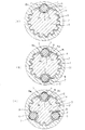
図10(a)、(b)及び(c)は、それぞれ本発明の第5実施の形態に係る車両ステアリング用伸縮軸の第1実施例、第2実施例及び第3実施例の断面図である。第1実施の形態と同様の構成には同じ符号を付し説明を省略する。
(Fifth embodiment)
FIGS. 10A, 10B, and 10C are cross-sectional views of a first example, a second example, and a third example, respectively, of a telescopic shaft for vehicle steering according to a fifth embodiment of the present invention. is there. The same components as those in the first embodiment are denoted by the same reference numerals and description thereof is omitted.
「第1実施例」
図10(a)に示す第1実施例では、スプライン嵌合された雄軸1と雌軸2からなる車両ステアリング用伸縮軸において、雄軸1と雌軸2の間の1箇所に、第1実施の形態と同等の予圧部を設けている。
“First Example”
In the first embodiment shown in FIG. 10A, in a telescopic shaft for vehicle steering composed of a
より詳しくは、図10(a)に示すように、車両ステアリング用伸縮軸(以後、伸縮軸と記す)は、相互に回転不能に且つ摺動自在にスプライン嵌合した雄軸1と雌軸2とからなる。
More specifically, as shown in FIG. 10A, a telescopic shaft for vehicle steering (hereinafter referred to as a telescopic shaft) is a
本第1実施例では、雄軸1の外周面にスプライン嵌合用の軸方向凸条14が複数延在して形成され、これに対応して雌軸2の内周面にスプライン嵌合用の軸方向溝16が複数延在して形成され、軸方向凸条14と軸方向溝16とがスプライン嵌合されてトルク伝達部を形成している。
In the first embodiment, a plurality of
雄軸1の外周面の1個所にスプライン嵌合用の軸方向凸条14に替えて略U字形状の第1の軸方向溝3(以後、軸方向溝3と記す)が延在して形成してある。これに対応して雌軸2の内周面には、軸方向溝3と対向する位置に略円弧状の第2の軸方向溝5(以後、軸方向溝5と記す)が延在して形成されている。軸方向溝3と軸方向溝5との間に予圧用の波型形状の弾性体8を介して、転動体7が介装されている。転動体7は雄軸1と雌軸2との軸方向に相対移動の際には転動し、回転の際には弾性体8拘束されてガタつきを防止する。
A substantially U-shaped first axial groove 3 (hereinafter referred to as an axial groove 3) is formed at one location on the outer peripheral surface of the
弾性体8は、その両側の平坦部8a、8aで軸方向溝3の両側の壁部3a、3aに圧接してあり、弾性体8全体が周方向に移動できないようになっている。そして弾性体8は転動体7に予圧を与えると共に、転動体7と軸方向凸条14を雌軸2に対してガタ付きのない程度に予圧する働きをする。このようにして本題1実施例の伸縮軸が構成されている。
The
本第1実施例の伸縮軸は、このような構造であるので、予圧部の存在によりそれぞれのトルク伝達部において雄軸1と雌軸2は常時摺動可能に接触しており、雄軸1と雌軸2との軸方向の相対移動の際には互いに摺動し、且つ転動体7は転動する。
Since the telescopic shaft of the first embodiment has such a structure, the
以上のように構成した伸縮軸では、雄軸1と雌軸2の間にトルク伝達部である軸方向凸条14と軸方向溝16とをスプライン嵌合させると共に、転動体7を弾性体8を介して軸方向溝3と軸方向溝5の間に介装し、弾性体8により、転動体と軸方向凸条14とを雌軸2に対してガタ付きのない程度に予圧してある。
In the telescopic shaft configured as described above, the
トルク非伝達時は、雄軸1と雌軸2の間のガタ付きを確実に防止することができると共に、雄軸1と雌軸2が軸方向に相対移動する際には、ガタ付きのない安定した摺動荷重で雄軸1と雌軸2とを軸方向に摺動することができる。
When torque is not transmitted, rattling between the
トルク伝達時には、トルク伝達部の軸方向凸条14と軸方向溝16とのスプライン嵌合部が主なトルク伝達の役割を果たし、予圧部では弾性体8が弾性変形して球状体7を雄軸1と雌軸2の間で周方向に拘束してガタつきを防止することが出来る。
At the time of torque transmission, the spline fitting portion between the
その他の作用、効果は、第1実施の形態と同様であり説明を省略する。 Other operations and effects are the same as those in the first embodiment, and a description thereof will be omitted.
「第2実施例」
図10(b)に示す第2実施例では、スプライン嵌合された雄軸1と雌軸2からなる車両ステアリング伸縮軸において、第1実施例と同等の予圧部を雄軸1と雌軸2との間に周方向に180度間隔で配置している。そして、予圧部の間それぞれに、第1実施例と同等のトルク伝達部を複数箇所設けている。
"Second Example"
In the second embodiment shown in FIG. 10B, a preload portion equivalent to that of the first embodiment is provided on the
このように、2箇所に予圧部を設けることによって、第1実施例に比べ、さらに摺動荷重を低減することができると共に、ガタつきを防止することが出来る。その他の構成、作用、効果は第1実施例と同様であり説明を省略する。 Thus, by providing the preload portion at two locations, it is possible to further reduce the sliding load and prevent rattling as compared with the first embodiment. Other configurations, operations, and effects are the same as those in the first embodiment, and a description thereof will be omitted.
「第3実施例」
図10(c)に示す第3実施例では、スプライン嵌合された雄軸1と雌軸2からなる車両ステアリング伸縮軸において、雄軸1と雌軸2との間に、第1実施の形態と同様の予圧部を周方向に120度で等配して設けている。そして、予圧部の間それぞれに、第1実施例と同等のトルク伝達部を複数箇所設けている。
“Third Example”
In the third embodiment shown in FIG. 10C, in the vehicle steering telescopic shaft comprising the
このように、周方向の3箇所に予圧部を設けることによって、第1および第2実施例に比べ、さらに摺動荷重を低減することができると共に、がたつきを防止することが出来る。また、予圧部を周方向に120度で等配していることによって、軸の偏心も改善することが出来るので摺動荷重の偏りも低減することが出来る。その他の構成、作用、効果は第1及び第2実施例と同様であり説明を省略する。 Thus, by providing the preload portion at three locations in the circumferential direction, the sliding load can be further reduced and rattling can be prevented as compared with the first and second embodiments. Further, since the preload portion is equally arranged at 120 degrees in the circumferential direction, the eccentricity of the shaft can be improved, and the unevenness of the sliding load can be reduced. Other configurations, operations, and effects are the same as those of the first and second embodiments, and the description thereof is omitted.
なお、上述の第1実施例から第3実施例において、摺動面および転動面にグリースを塗布することによりさらに低い摺動荷重を得ることが出来る。また、雄軸に形成されている軸方向凸条14が雌軸に側に、雌軸に形成されている軸方向溝16が雄軸側に形成されていても本願実施の形態と同様の作用、効果が得られる。また、軸方向溝5の曲率と転動体7の曲率が異なっていて、両者は点接触するように形成されていても良い。また、転動体7は球状体であっても良い。さらに、弾性体8は板バネであっても良い。
In the first to third embodiments, a lower sliding load can be obtained by applying grease to the sliding surface and the rolling surface. Further, even if the
(第6実施の形態)
図11(a)、(b)及び(c)は、それぞれ本発明の第6実施の形態に係る車両ステアリング用伸縮軸の第1実施例、第2実施例及び第3実施例の断面図である。第5実施の形態と同様の構成には同じ符号を付し説明を省略する。
(Sixth embodiment)
FIGS. 11A, 11B, and 11C are cross-sectional views of the first, second, and third examples of the vehicle steering telescopic shaft according to the sixth embodiment of the present invention, respectively. is there. The same components as those in the fifth embodiment are denoted by the same reference numerals and description thereof is omitted.
本第6実施の形態と第5実施の形態との相違は、雄軸1の外周面に固体潤滑膜11を形成したことにある。このように、雄軸1の外周面に固体潤滑膜11を形成することによって、トルク伝達部の軸方向凸条14と軸方向溝16との接触抵抗を低くすることが出来るため、総摺動荷重(転がりと滑りが両方作用している本発明の構造において、通常使用時に発生する摺動荷重を言う)を第5実施の形態の場合に比べて低くすることが出来る。そして、本第6実施の形態の場合も、第5実施の形態と同様の作用、効果が得られる。
The difference between the sixth embodiment and the fifth embodiment is that a
固体潤滑皮膜としては、二酸化モリブデンの紛体を樹脂中に分散混合し、それを吹き付けまたは浸漬後に焼き付けて皮膜を形成したものや、PTFE(四フッ化エチレン)を樹脂中に分散混合し、それを吹き付けまたは浸漬後に焼き付けて皮膜を形成したもの等が用いられる。 As a solid lubricating film, a powder of molybdenum dioxide is dispersed and mixed in a resin, and then sprayed or dipped and baked to form a film, or PTFE (tetrafluoroethylene) is dispersed and mixed in a resin. What formed the film | membrane by baking after spraying or immersion is used.
なお、摺動面および転動面にグリースを塗布することによりさらに低い摺動荷重を得ることが出来る。また、雄軸に形成されている軸方向凸条14が雌軸に側に、雌軸に形成されている軸方向溝16が雄軸側に形成されていても本願実施の形態と同様の作用、効果が得られる。また、軸方向溝5の曲率と転動体7の曲率が異なっていて、両者は点接触するように形成されていても良い。また、転動体7は球状体であっても良い。さらに、弾性体8は板バネであっても良い。
Note that a lower sliding load can be obtained by applying grease to the sliding surface and the rolling surface. Further, even if the
(第7実施の形態)
図12(a)、(b)及び(c)は、それぞれ本発明の第7実施の形態に係る車両ステアリング用伸縮軸の第1実施例、第2実施例及び第3実施例の断面図である。第5、第6実施の形態と同様の構成には同じ符号を付し説明を省略する。
(Seventh embodiment)
12A, 12B, and 12C are cross-sectional views of the first, second, and third examples of the vehicle steering telescopic shaft according to the seventh embodiment of the present invention, respectively. is there. The same components as those in the fifth and sixth embodiments are denoted by the same reference numerals and description thereof is omitted.
本第7実施の形態と第5実施の形態との相違は、雌軸2の内周面に固体潤滑膜11を形成したことにある。このように、雌軸2の内周面に固体潤滑膜11を形成することによって、トルク伝達部の軸方向凸条14と軸方向溝16との接触抵抗を低くすることが出来るため、総摺動荷重(転がりと滑りが両方作用している本発明の構造において、通常使用時に発生する摺動荷重を言う)を第5実施の形態の場合に比べて低くすることが出来る。そして、本第7実施形態の場合も、第5実施の形態と同様の作用、効果が得られる。
The difference between the seventh embodiment and the fifth embodiment is that a
固体潤滑皮膜としては、二酸化モリブデンの紛体を樹脂中に分散混合し、それを吹き付けまたは浸漬後に焼き付けて皮膜を形成したものや、PTFE(四フッ化エチレン)を樹脂中に分散混合し、それを吹き付けまたは浸漬後に焼き付けて皮膜を形成したもの等が用いられる。 As a solid lubricating film, a powder of molybdenum dioxide is dispersed and mixed in a resin, and then sprayed or dipped and baked to form a film, or PTFE (tetrafluoroethylene) is dispersed and mixed in a resin. What formed the film | membrane by baking after spraying or immersion is used.
なお、摺動面および転動面にグリースを塗布することによりさらに低い摺動荷重を得ることが出来る。また、雄軸に形成されている軸方向凸条14が雌軸に側に、雌軸に形成されている軸方向溝16が雄軸側に形成されていても本願実施の形態と同様の作用、効果が得られる。また、軸方向溝5の曲率と転動体7の曲率が異なっていて、両者は点接触するように形成されていても良い。また、転動体7は球状体であっても良い。さらに、弾性体8は板バネであっても良い。
Note that a lower sliding load can be obtained by applying grease to the sliding surface and the rolling surface. Further, even if the
なお、上記第4から第6実施の形態では、軸方向凸条と軸方向溝がスプライン嵌合用の場合について説明したが、セレーション嵌合用であっても、また単に凸凹嵌合用であっても同様の作用、効果が得られる。 In the fourth to sixth embodiments, the case where the axial ridges and the axial grooves are for spline fitting has been described. However, the same applies for serration fitting or simply for uneven fitting. The effects and effects are obtained.
(その他関連事項)
本発明の全ての実施の形態において、中実の雄軸を中空に、中空の雄軸を中実に置き換えても良い。
(Other related matters)
In all the embodiments of the present invention, the solid male shaft may be replaced with a hollow, and the hollow male shaft may be replaced with a solid.
また、本発明の全ての実施の形態において、下記の事が言える。雌軸の先端を内側に加締めることで、雄軸の引抜を防止し、分解できない構造にしても良い。転動体7は、熱処理され、且つ研磨されたものを使用してもよい。雄軸1の外周面に、PTFE(四フッ化エチレン)または、二硫化モリブデンを含む樹脂皮膜処理を施したものを使用してもよい。雄軸1を冷間引き抜き成型で製造した中実または中空の鋼材を使用してもよい。雄軸1を冷間押し出し成形で製造したアルミニウム材を使用してもよい。雄軸1を冷間鍛造で製造した中実の鋼材または、アルミニウム材を使用してもよい。雌軸2を冷間引き抜き成型で製造した中空の鋼材を使用してもよい。雄軸を冷間鍛造成形する際には、素材に金属石鹸処理(ボンデ処理)を施すことが望ましい。雌軸は中空の鋼材を素材として用い、金属石鹸処理(ボンデ処理)した後に、求める径に絞り又は拡管加工し、溝部をプレス成形しても良い。雌軸2は窒化処理されていてもよい。雌軸2の内周面にPTFE(四フッ化エチレン)または、二硫化モリブデンを含む樹脂皮膜処理を施したものを使用してもよい。
Moreover, the following can be said in all the embodiments of the present invention. A structure in which the male shaft is prevented from being pulled out and can not be disassembled by crimping the tip of the female shaft inward may be adopted. The rolling
また、本発明の全ての実施の形態において、下記の数値範囲が用いられることが望ましい。
・転動体であるボール直径は、乗用車に使われる用途では、Φ3〜6mm程度。
・ボール径とボール及び軸方向凸条のP.C.D.比は1:3.5〜5.0程度。
・雄軸の軸径は、一般的に乗用車として必要とされる捩り強度が250Nm以上であることから、一般的な機械構造用炭素鋼を使用した場合、13mm以上。
・トルクを負荷しない状態で、ボールの接触圧が1500MPa以下。
・トルクを100Nm負荷した状態で、ボールの接触圧が2000MPa以下。
・トルクを100Nm負荷した状態で、軸方向凸条の接触圧が2000MPa以下。
・弾性体である板バネの板厚とボール径の比は、1:10〜20程度。
In all embodiments of the present invention, the following numerical ranges are preferably used.
・ The ball diameter, which is a rolling element, is about Φ3-6mm for applications used in passenger cars.
・ P. of ball diameter and ball and axial ridge. C. D. The ratio is about 1: 3.5 to 5.0.
-The shaft diameter of the male shaft is generally 13 mm or more when using carbon steel for general mechanical structures because the torsional strength generally required for passenger cars is 250 Nm or more.
-The contact pressure of the ball is 1500 MPa or less with no torque applied.
-The contact pressure of the ball is 2000 MPa or less with a torque of 100 Nm applied.
The contact pressure of the axial ridge is 2000 MPa or less with a torque of 100 Nm applied.
The ratio of the plate thickness of the leaf spring, which is an elastic body, to the ball diameter is about 1: 10-20.
本発明では、以上を総合すると従来の製品と比較して下記のことが言える。
・低コストである。
・安定した低スライド荷重を得ることができる。
・ガタがない。
・耐摩耗性に優れている。
・耐熱性に優れている。
・軽量化が可能である。
・機構が小さい。
・設計思想を変えずにあらゆる使用条件に対応することができる。
In the present invention, the following can be said in comparison with the conventional product in summary.
・ Low cost.
・ Stable low slide load can be obtained.
・ There is no backlash.
・ Excellent wear resistance.
・ Excellent heat resistance.
・ Weight reduction is possible.
・ The mechanism is small.
・ Can be used in all conditions without changing the design concept.
なお、特開2001−50293号公報、及びドイツ特許公開DE 3730393 A1号公報には、雄軸と雌軸に形成した軸方向溝に複数のボールを介装して弾性体により予圧した構造が開示してある。これに対して、本発明は、上述したように、「全列をボール転がり構造とした場合」又は「従来のスプライン嵌合とした場合」より著しく優れている。 Japanese Patent Application Laid-Open No. 2001-50293 and German Patent Publication DE 3730393 A1 disclose a structure in which a plurality of balls are interposed in an axial groove formed on a male shaft and a female shaft and preloaded by an elastic body. It is. On the other hand, as described above, the present invention is significantly superior to “when all rows have a ball rolling structure” or “when conventional spline fitting”.
また、欧州特許公開EP1078843A1号公報では、ニードルローラ、その保持器、ガタつき防止のためのレギュレーターでガタ付きを防止するという構造であるが、純粋な滑り摺動であるため、予圧荷重を大きくできない。よって、長期にわたってガタつきを防止することや、高剛性を得ることが非常に困難である。 In addition, in European Patent Publication No. EP1078843A1, the needle roller, its retainer, and a regulator for preventing rattling are structured to prevent rattling, but because of pure sliding sliding, the preload cannot be increased. . Therefore, it is very difficult to prevent rattling and to obtain high rigidity over a long period of time.
それに対し、本発明では、前述したとおり、転がり構造を部分的に採用しており、且つ、ガタ付きを防止するための手段も違うため、
・摩擦抵抗が低いため、摺動荷重を低く抑えられる。
・予圧荷重を高くすることができ、長期にわたるガタつきの防止と高剛性が同時に得られる。といったことが極めて優れている。
On the other hand, in the present invention, as described above, the rolling structure is partially adopted, and the means for preventing backlash is different.
・ Sliding load can be kept low because of low frictional resistance.
・ Preload can be increased, and long-term rattling and high rigidity can be achieved at the same time. Is extremely excellent.
なお、本発明は、上述した実施の形態に限定されず、種々変形可能である。 In addition, this invention is not limited to embodiment mentioned above, A various deformation | transformation is possible.
(発明の効果)
以上説明したように、本発明によれば、雄軸と雌軸の間の回転方向ガタ付きを確実に防止して、高剛性の状態でトルクを伝達することができる車両ステアリング用伸縮軸を提供することが出来る。
(The invention's effect)
As described above, according to the present invention, there is provided a telescopic shaft for vehicle steering capable of reliably preventing backlash in the rotational direction between the male shaft and the female shaft and transmitting torque in a highly rigid state. I can do it.
1 雄軸
2 雌軸
3 第1の軸方向溝
3a 壁部
4、14 軸方向凸条
5 第2の軸方向溝
6、16 軸方向溝
7 転動体
8 弾性体
8a 平坦部
9、12 ストッパープレート
10 加締め部
11 固体潤滑皮膜
100 メンバ
101 アッパブラケット
102 ロアブラケット
103 ステアリングコラム
104 ステアリングシャフト
105 ステアリングホイール
106 ユニバーサルジョイント
107 ロアステアリングシャフト部
108 操舵軸継手
109 ピニオンシャフト
110 フレーム
111 弾性体
112 ステアリングラック
120 アッパステアリングシャフト部
DESCRIPTION OF
Claims (13)
前記雄軸の外周部と前記雌軸の内周部にそれぞれ設けられ、互いに接触して回転の際にはトルクを伝達するトルク伝達部と、
前記トルク伝達部とは異なる位置の前記雄軸の外周部と前記雌軸の内周部の間に設けられ、前記雄軸と前記雌軸との軸方向相対移動の際には転動する転動体と、該転動体に径方向に隣接して配置され、該転動体を介して前記雄軸と前記雌軸とに予圧を与える弾性体とからなる予圧部と、
を具備してなることを特徴とする車両ステアリング用伸縮軸。 In the telescopic shaft for vehicle steering, which is incorporated in the steering shaft of the vehicle and the male shaft and the female shaft are slidably fitted to each other,
A torque transmitting portion provided on each of the outer peripheral portion of the male shaft and the inner peripheral portion of the female shaft, and contacting each other to transmit torque when rotating;
Roller that is provided between the outer peripheral part of the male shaft and the inner peripheral part of the female shaft at a position different from the torque transmission part, and rolls when the male shaft and the female shaft move relative to each other in the axial direction. A preloading portion comprising a moving body and an elastic body that is arranged adjacent to the rolling element in the radial direction and applies preload to the male shaft and the female shaft via the rolling body;
A telescopic shaft for vehicle steering, comprising:
前記転動体と前記弾性体は、該第1および第2の軸方向溝間に配置されていることを特徴とする請求項1に記載の車両ステアリング用伸縮軸。 The preload portion includes a first axial groove provided on the outer peripheral surface of the male shaft, and a second axial direction provided on the inner peripheral surface of the female shaft so as to face the first axial groove. Having a groove,
The telescopic shaft for vehicle steering according to claim 1, wherein the rolling element and the elastic body are disposed between the first and second axial grooves.
前記トルク伝達部は、隣り合う前記予圧部の間に複数配置されていることを特徴とする請求項1に記載の車両ステアリング用伸縮軸。 A plurality of the preload portions are disposed between the male shaft and the female shaft,
2. The telescopic shaft for vehicle steering according to claim 1, wherein a plurality of the torque transmitting portions are arranged between the adjacent preload portions.
Priority Applications (1)
| Application Number | Priority Date | Filing Date | Title |
|---|---|---|---|
| JP2005129888A JP2005231625A (en) | 2005-04-27 | 2005-04-27 | Extendable shaft for vehicle steering |
Applications Claiming Priority (1)
| Application Number | Priority Date | Filing Date | Title |
|---|---|---|---|
| JP2005129888A JP2005231625A (en) | 2005-04-27 | 2005-04-27 | Extendable shaft for vehicle steering |
Related Parent Applications (1)
| Application Number | Title | Priority Date | Filing Date |
|---|---|---|---|
| JP2002268867A Division JP3797304B2 (en) | 2002-09-13 | 2002-09-13 | Telescopic shaft for vehicle steering |
Publications (2)
| Publication Number | Publication Date |
|---|---|
| JP2005231625A true JP2005231625A (en) | 2005-09-02 |
| JP2005231625A5 JP2005231625A5 (en) | 2005-11-04 |
Family
ID=35014997
Family Applications (1)
| Application Number | Title | Priority Date | Filing Date |
|---|---|---|---|
| JP2005129888A Pending JP2005231625A (en) | 2005-04-27 | 2005-04-27 | Extendable shaft for vehicle steering |
Country Status (1)
| Country | Link |
|---|---|
| JP (1) | JP2005231625A (en) |
Cited By (5)
| Publication number | Priority date | Publication date | Assignee | Title |
|---|---|---|---|---|
| WO2008056636A1 (en) * | 2006-11-10 | 2008-05-15 | Jtekt Corporation | Vehicle steering shaft and vehicle steering device |
| JP2008261497A (en) * | 2007-04-12 | 2008-10-30 | Mando Corp | Universal joint |
| JP2010116955A (en) * | 2008-11-12 | 2010-05-27 | Nsk Ltd | Extensible rotation transmission shaft |
| JP2013142437A (en) * | 2012-01-10 | 2013-07-22 | Nsk Ltd | Telescopic shaft |
| WO2016002912A1 (en) * | 2014-07-03 | 2016-01-07 | 日本精工株式会社 | Extensible rotation transmission shaft |
-
2005
- 2005-04-27 JP JP2005129888A patent/JP2005231625A/en active Pending
Cited By (8)
| Publication number | Priority date | Publication date | Assignee | Title |
|---|---|---|---|---|
| WO2008056636A1 (en) * | 2006-11-10 | 2008-05-15 | Jtekt Corporation | Vehicle steering shaft and vehicle steering device |
| US8052535B2 (en) | 2006-11-10 | 2011-11-08 | Jtekt Corporation | Motor vehicle steering shaft and motor vehicle steering system |
| JP2008261497A (en) * | 2007-04-12 | 2008-10-30 | Mando Corp | Universal joint |
| JP2010116955A (en) * | 2008-11-12 | 2010-05-27 | Nsk Ltd | Extensible rotation transmission shaft |
| JP2013142437A (en) * | 2012-01-10 | 2013-07-22 | Nsk Ltd | Telescopic shaft |
| WO2016002912A1 (en) * | 2014-07-03 | 2016-01-07 | 日本精工株式会社 | Extensible rotation transmission shaft |
| JPWO2016002912A1 (en) * | 2014-07-03 | 2017-04-27 | 日本精工株式会社 | Telescopic rotation transmission shaft |
| US10330141B2 (en) | 2014-07-03 | 2019-06-25 | Nsk Ltd. | Extensible rotation transmission shaft |
Similar Documents
| Publication | Publication Date | Title |
|---|---|---|
| JP3797304B2 (en) | Telescopic shaft for vehicle steering | |
| JP4696916B2 (en) | Telescopic shaft for vehicle steering | |
| JP4770193B2 (en) | Telescopic shaft for vehicle steering | |
| US7481130B2 (en) | Vehicle steering telescopic shaft | |
| JP4419841B2 (en) | Telescopic shaft for vehicle steering | |
| JP4254194B2 (en) | Telescopic shaft for vehicle steering | |
| EP1568569B1 (en) | Extendable shaft for vehicle steering | |
| WO2004056638A1 (en) | Telescopic shaft for motor vehicle steering | |
| JP2007255546A (en) | Telescopic shaft and steering device equipped with telescopic shaft | |
| JP2005231625A (en) | Extendable shaft for vehicle steering | |
| JP4428117B2 (en) | Telescopic shaft for vehicle steering | |
| JP2007008286A (en) | Telescopic column for vehicle steering | |
| JP2005153677A (en) | Telescopic shaft for vehicle steering | |
| JP2003247560A (en) | Expansion axle for car steering | |
| JP2005349964A (en) | Telescopic shaft for vehicle steering | |
| JP2005299779A (en) | Flexible shaft used for steering gear of vehicle | |
| JP2005306216A (en) | Steering system for vehicle | |
| JP2011073543A5 (en) | ||
| JP2005324599A (en) | Telescopic shaft for vehicle steering | |
| JP2005313693A (en) | Telescopic shaft for vehicle steering | |
| JP2003118594A (en) | Vehicle steering expansion shaft | |
| WO2005102820A1 (en) | Collapsible column for steering of vehicle | |
| JP2003063414A (en) | Vehicle steering extension rod | |
| JP2006205833A (en) | Telescopic shaft for vehicle steering, and method for fixing shaft end portion | |
| JP2005225444A (en) | Telescopic shaft for vehicular steering |
Legal Events
| Date | Code | Title | Description |
|---|---|---|---|
| A521 | Written amendment |
Free format text: JAPANESE INTERMEDIATE CODE: A523 Effective date: 20050912 |
|
| A621 | Written request for application examination |
Free format text: JAPANESE INTERMEDIATE CODE: A621 Effective date: 20050912 |
|
| A977 | Report on retrieval |
Free format text: JAPANESE INTERMEDIATE CODE: A971007 Effective date: 20080703 |
|
| A131 | Notification of reasons for refusal |
Free format text: JAPANESE INTERMEDIATE CODE: A131 Effective date: 20080722 |
|
| A02 | Decision of refusal |
Free format text: JAPANESE INTERMEDIATE CODE: A02 Effective date: 20081209 |