JP2005297710A - Power transmission device for work vehicle - Google Patents
Power transmission device for work vehicle Download PDFInfo
- Publication number
- JP2005297710A JP2005297710A JP2004115558A JP2004115558A JP2005297710A JP 2005297710 A JP2005297710 A JP 2005297710A JP 2004115558 A JP2004115558 A JP 2004115558A JP 2004115558 A JP2004115558 A JP 2004115558A JP 2005297710 A JP2005297710 A JP 2005297710A
- Authority
- JP
- Japan
- Prior art keywords
- shaft
- transmission
- pto
- power
- case
- Prior art date
- Legal status (The legal status is an assumption and is not a legal conclusion. Google has not performed a legal analysis and makes no representation as to the accuracy of the status listed.)
- Pending
Links
- 230000005540 biological transmission Effects 0.000 title claims abstract description 203
- 230000007246 mechanism Effects 0.000 claims abstract description 28
- 230000003028 elevating effect Effects 0.000 description 5
- 238000010586 diagram Methods 0.000 description 3
- 239000003921 oil Substances 0.000 description 3
- 238000010276 construction Methods 0.000 description 2
- 238000007599 discharging Methods 0.000 description 2
- 230000000694 effects Effects 0.000 description 2
- 238000012423 maintenance Methods 0.000 description 2
- 230000008602 contraction Effects 0.000 description 1
- 239000010720 hydraulic oil Substances 0.000 description 1
- 238000004519 manufacturing process Methods 0.000 description 1
Images

Landscapes
- Arrangement And Driving Of Transmission Devices (AREA)
- Structure Of Transmissions (AREA)
- Arrangement Of Transmissions (AREA)
Abstract
【課題】トラクタのような作業車両では、ミッションケース内の各種動力伝達機構を効率良くレイアウトすることが、車両全体のコンパクト化に大きく寄与することができる。
【解決手段】トラクタのミッションケース1の左右略中心部X−Xに、前記エンジンEからの動力を入力するケース入力軸62と、同軸62と常時噛合ギヤ63,73fを介して駆動される中継軸73を支持する。前記中継軸73に対して左右一側に、走行系動力伝達機構を構成し、他側に作業機系動力伝達機構を構成する。詳しくは走行系の前後進クラッチ83とPTOクラッチCpを前後及び高さを重複して配置する。また前記走行系変速部M2とPTO変速部Mpを前後及び高さを重複して配置する。
【選択図】 図7In a work vehicle such as a tractor, efficient layout of various power transmission mechanisms in a mission case can greatly contribute to downsizing of the entire vehicle.
[MEANS FOR SOLVING PROBLEMS] A case input shaft (62) for inputting power from the engine (E) to a substantially central portion (XX) on the left and right of a transmission case (1) of a tractor, and a relay driven by a coaxial (62) and constantly meshing gears (63, 73f) The shaft 73 is supported. A traveling system power transmission mechanism is configured on one side of the relay shaft 73 on the left and right sides, and a work machine system power transmission mechanism is configured on the other side. Specifically, the forward / reverse clutch 83 and the PTO clutch Cp of the traveling system are arranged overlapping in the front-rear direction and the height. In addition, the traveling system transmission unit M2 and the PTO transmission unit Mp are arranged to overlap in the front-rear direction and the height.
[Selection] Figure 7
Description
この発明は、農業用トラクタの農業用、建築、運搬用等の作業車両の動力伝達装置の構成に関する。 The present invention relates to a configuration of a power transmission device for a work vehicle for agriculture, construction, transportation, etc. of an agricultural tractor.
従来、農業用トラクタには、エンジンの回転動力をミッションケース内に入力し、前記回転動力を走行系動力伝達装置を介して前後輪へ伝達すると共に、作業機系動力伝達装置を介して車体後部や下部、或いは前部に突設するPTO軸へ伝達して、作業機を駆動する構成となっている。そして、前記作業機系動力伝達装置には、この回転動力の伝達を入り切りするPTOクラッチ、回転動力を逆転させる逆転PTO機構、回転動力を変速するPTO変速機構等を備える構成となっている。
ところで、前記トラクタのような作業車両には、車長を法で定められた車長内に構成したり、狭い作業地での操作性を向上させるべく、車体全体を極力コンパクトに構成する必要があり、特に前記ミッションケース内の各種の動力伝達機構を効率良くレイアウトすることは、車長や車高のコンパクト化に寄与することができる。 By the way, in a work vehicle such as the tractor, it is necessary to configure the entire vehicle body as compact as possible in order to configure the vehicle length within the legal vehicle length or to improve the operability in a narrow work site. In particular, efficient layout of the various power transmission mechanisms in the transmission case can contribute to a reduction in the vehicle length and height.
以上のような課題に鑑みて、この発明では、作業車両の動力伝達装置を以下のように構成した。 In view of the above problems, in the present invention, a power transmission device for a work vehicle is configured as follows.
即ち、請求項1の発明では、エンジン(E)の回転動力をミッションケース(1)内に入力し、前記動力をケース(1)内に備えた前後進切替部(M1)及び走行変速部(M2〜M4)を有する走行系動力伝達装置を介して駆動輪(2F,2R)へ伝達すると共に、前記動力を作業機系動力伝達入切クラッチ(Cp)及びPTO変速部(Mp)を有する作業機系動力伝達装置を介してPTO軸(29)へ伝達する作業車両の動力伝達装置において、
前記ミッションケース(1)の左右略中心部(X−X)に、前記エンジン(E)からの動力を入力するケース入力軸(62)と、同軸(62)と常時噛合ギヤ(63,73f)を介して駆動される中継軸(73)を支持し、
前記中継軸(73)に対して前記ミッションケース(1)の左右一側に、走行系動力伝達装置を構成する走行系伝動軸(80)を支持すると共に、同軸(80)上に前記中継軸(73)からの動力回転方向を正逆切り替える前記前後進切替部(M1)の前後進切替クラッチ(83f、83r)を備える一方、
前記中継軸(73)に対して前記ミッションケース(1)の左右他側に、PTO系動力伝達装置を構成するPTO系伝動軸(75)を支持すると共に、同軸(75)上に、且つ側面視前記前後進切替クラッチ(83f、83r)の高さ及び前後幅を重複させて前記中継軸(73)からの動力を入切操作する前記作業機系動力伝達クラッチ(Cp)を構成したことを特徴とする作業車両の動力伝達装置。
(請求項1の作用)
以上のように構成した請求項1の発明では、エンジン(E)の回転動力がケース入力軸(62)によりミッションケース(1)内に略中心部(X−X)に取り入れられ、走行系の回転動力は、中継軸(73)から左右一側に振られて、前後進切替クラッチ(83f、83r)、走行系伝動軸(80)、走行変速部(M2〜M4)を経由して駆動輪(2F,2R)へ伝達される。一方、作業機系の回転動力は、前記中継軸(73)から左右他側に振られて、作業機系動力伝達クラッチ(Cp)、PTO系伝動軸(75)、PTO変速部(Mp)を経由してPTO軸(29)へ伝達される。
That is, according to the first aspect of the present invention, the rotational power of the engine (E) is input into the transmission case (1), and the forward / reverse switching unit (M1) and the travel transmission unit (with the power in the case (1)) ( The work is transmitted to the drive wheels (2F, 2R) through a traveling system power transmission device having M2 to M4), and the power is operated with a work machine system power transmission on / off clutch (Cp) and a PTO transmission (Mp). In the power transmission device of the work vehicle that transmits to the PTO shaft (29) via the mechanical power transmission device,
A case input shaft (62) for inputting power from the engine (E), a coaxial (62), and a constant meshing gear (63, 73f) to the left and right center (XX) of the transmission case (1) Supporting the relay shaft (73) driven through
On the left and right sides of the transmission case (1) with respect to the relay shaft (73), a traveling system transmission shaft (80) constituting a traveling system power transmission device is supported, and the relay shaft is coaxially mounted on the relay shaft (80). While including the forward / reverse switching clutch (83f, 83r) of the forward / reverse switching section (M1) for switching the power rotation direction from (73) forward and reverse,
A PTO system transmission shaft (75) constituting a PTO system power transmission device is supported on the left and right other sides of the transmission case (1) with respect to the relay shaft (73), on the same axis (75), and on the side surface. As a result, the work machine power transmission clutch (Cp) configured to turn on / off the power from the relay shaft (73) by overlapping the height and the front / rear width of the forward / reverse switching clutch (83f, 83r). A power transmission device for a working vehicle.
(Operation of claim 1)
In the invention of
また請求項2の発明では、前記走行系動力伝達装置を構成する走行系伝動軸(80)の同軸芯延長上に、前記走行変速駆動軸(84)若しくは走行変速被駆動軸(87)を支持して走行変速部(M2)を構成すると共に、
前記作業機系動力伝達装置を構成するPTO系伝動軸(75)の延長上に、前記走行変速部(M2)の高さ及び前後幅を重複させてPTO変速ギヤ(74a,74b…)を支持してPTO変速部(Mp)を構成したことと特徴とする請求項1に記載の作業車両の動力伝達装置。
(請求項2の作用)
以上のように構成した請求項2の発明では、前記中継軸(73)から左右一側に振られた走行系回転動力は、走行変速駆動軸(84)と走行変速被駆動軸(87)を有する走行変速部(M2)にて変速され、駆動輪(2F,2R)へ伝達される。また前記中継軸(73)から左右他側に振られたPTO系回転動力は、PTO変速駆動軸(75)とPTO変速被駆動軸(77)を有するPTO変速部(Mp)にて変速されPTO軸(29)へ伝達される。
According to a second aspect of the present invention, the travel transmission drive shaft (84) or the travel transmission driven shaft (87) is supported on the coaxial core extension of the travel system transmission shaft (80) constituting the travel system power transmission device. And configure the traveling speed change part (M2),
The PTO transmission gears (74a, 74b,...) Are supported on the extension of the PTO transmission shaft (75) constituting the work machine power transmission device by overlapping the height and the front-rear width of the traveling transmission unit (M2). The power transmission device for a work vehicle according to
(Operation of claim 2)
In the invention according to
また請求項3の発明では、前記PTO変速部(Mp)には、前記ミッションケース(1)の左右他側で且つ前記変速被駆動軸(77)と略同高さに、前記PTO変速駆動軸(75)からPTO変速被駆動軸(77)への動力回転方向を逆転して伝達するPTOカウンター軸(78)を備え、逆転PTO機構を構成したことを特徴とする請求項2に記載の作業車両の動力伝達装置。
(請求項3の作用)
以上のように構成した請求項3の発明では、請求項2の作用に加え、前記中継軸(73)から左右他側に振られたPTO系回転動力は、PTO変速駆動軸(75)からPTOカウンター軸(78)介してPTO変速被駆動軸(77)へ逆転して伝達される。
According to a third aspect of the present invention, the PTO speed change drive shaft (Mp) includes the PTO speed change drive shaft on the left and right other sides of the transmission case (1) and at substantially the same height as the speed change driven shaft (77). The work according to
(Operation of claim 3)
In the invention of
これにより、請求項1に記載の発明では、前記中継軸(73)に対して前記ミッションケース(1)の左右他側に、作業機系動力伝達装置を構成するPTO系伝動軸(75)を支持すると共に、同軸(75)上で、且つ側面視、走行系の前後進切替クラッチ(83f、83r)の高さ及び前後幅を重複させて前記中継軸(73)からの動力を入切操作する前記動力伝達クラッチ(Cp)を構成したので、特にミッションケース(1)前部の上下幅及び前後幅を短縮することができて、ひいては車両全体をコンパクトに構成することができる。
Thereby, in invention of
また請求項2に記載の発明では、請求項1の効果に加え、前記作業機系動力伝達装置を構成するPTO伝動軸(75)の延長上に、前記走行変速部(M2)の高さ及び前後幅を重複させてPTO変速ギヤ(74a,74b…)を支持してPTO変速部(Mp)を構成したので、特にミッションケース(1)中間部の上下幅及び前後幅を短縮することができる。
In the invention according to
また請求項3に記載の発明では、請求項2の効果に加え、前記PTO変速部(Mp)には、前記ミッションケース(1)の左右他側で且つ前記変速被駆動軸(77)と略同高さに、前記PTO変速駆動軸(75)からPTO変速被駆動軸(77)への動力回転方向を逆転して伝達するPTOカウンター軸(78)を備えたので、前記PTO変速機構に逆転PTO機構を構成する場合でも、前記同様ミッションケース(1)中間部の上下幅及び前後幅を短縮することができる。また前記逆転PTO機構をミッションケース(1)の他の個所に備える場合と比較して、逆転PTO機構を切換操作するシフタ及び変速操作するシフタをケース一局部に集中配置することができるので、生産組付時やメンテナンス時の工数を省力化することができる。更に前記シフタを操作するPTOレバーの操作面においても、単一のレバーで略同一の操作ストロークで変速及び逆転に切替操作することができて、操作性を向上するとができる。
In the invention according to
以下、図例に基づいて、この発明を搭載したトラクタTについて説明する。 Hereinafter, a tractor T equipped with the present invention will be described with reference to the drawings.
最初にトラクタTの全体構成について説明する。 First, the overall configuration of the tractor T will be described.
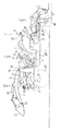
トラクタTは、図1に示すように、車体前部にエンジンEを設け、エンジンEの周囲をボンネット21で覆うと共に、このボンネット21の後部にハンドルポスト22を備えてステアリングハンドル23を突設支持する構成となっている。そして前記ステアリングハンドル23の回転操作によって左右前輪2F,2Fを操向する構成となっている。
As shown in FIG. 1, the tractor T is provided with an engine E at the front of the vehicle body, covers the periphery of the engine E with a
また前記エンジンEの後部にはミッションケース1が連結され、同ケース1の後部左右両側にアクスルハウジング25を連結して左右後輪2R,2Rを軸装する構成となっている。またこのミッションケース1の後上部には、油圧リフトシリンダを内装するシリンダケース27を設け、前記シリンダのピストンを駆動することにより同ケース1の左右に備えたリフトアーム28,28を昇降回動する構成となっている。また前記ミッションケース1の後側には三点リンク機構を備え、同リンク機構に後部作業機(図例ではロータリ耕耘機R)を連結可能に構成している。そして前記リフトアーム28,28と前記三点リンク機構を連結し、前記リフトアーム28,28の上下回動操作で後部作業機を昇降制御すると共に、またケース背面に突設するPTO軸29の回転をユニバーサルジョイント30を介して伝達することで同作業機Rの作業部、例えば前記ロータリ耕耘機Rであれば耕耘軸26を駆動する構成となっている。
The
また前記ミッションケース1の上方には、フロア6が支持され、この左右両側端を前記後輪2R,2Rの前方から上方及び内側を覆うフェンダ3に接合させ、前記フェンダ3,3間のフロア6の中央部に、操縦席32を設ける構成となっている。
Further, a
また前記ハンドルポスト22の下方には、トラクタTの走行や作業機操作を行うクラッチペタル33やブレーキペタル等のペタル類が配置され、また操縦席32の左方には変速レバー34や二駆四駆切替レバー等が配置され、右方には前部作業機操作レバー(以下、ローダ作業機操作レバー7)や後部作業機操作レバー(以下、作業機昇降レバー36)等が配置されている。
Below the
次にトラクタTに装着する前部作業機、ここではフロントローダ作業機19について説明する。
Next, the front work machine to be mounted on the tractor T, here, the front
前記エンジンEを取り付けるエンジン取付ブラケット41の後部には、前記ボンネット21の左右両側方にブーム支持支柱42,42を立設し、この左右の夫れ夫れの支柱42にリフトブーム11及び先端部のバケット12を有するフロントローダ19を装着する構成となっている。符号43はリフトブーム11をブーム軸P1の周りに昇降させるブーム昇降シリンダ、45はバケット12をリフトブーム11先端のダンプ軸P2の周りにダンプするバケット回動シリンダを示す。
At the rear part of the
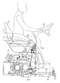
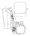
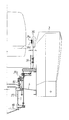
また前記ブーム昇降シリンダ43へ圧油を給排するブーム昇降用油圧バルブ4や、バケット回動シリンダ45へ圧油を給排するバケット回動用油圧バルブ5は、図2と図3に示すように、前記操縦席32の下方のミッションケース1の左側面に備える構成となっている。
As shown in FIGS. 2 and 3, the boom elevating
詳しくは、ブーム昇降用及びバケット回動用油圧バルブ4,5は二連のバルブを内外に重合させて貫通ボルトでミッションケース1に取付ける。また前記ブーム昇降用油圧バルブ4及びバケット回動用油圧バルブ5は、夫れ夫れバルブ筐体下部にブーム昇降用回路49、バケット回動用回路50を構成する配管を接続し、別途備えた油圧ポンプによってミッションケース1内の作動油をブーム昇降シリンダ43、或いはバケット回動シリンダ45へ連通する構成となっている。また前記ブーム昇降用回路49やバケット回動用回路50の回路中途部には、前記フロア6下方の狭いスペースで配管接続作業を極力容易に行うことができる様、接続コネクタ51,52を上下左右及び前後に位置をずらせて支持する構成となっている。
Specifically, the
また前記ブーム昇降用及びバケット回動用油圧バルブ4,5のバルブケースの上部には、左右方向の軸13周りに回動自在に支持するベルクランク形状の回動アーム14,15を設け、各回動アーム14,15の下端部を夫れ夫れの油圧バルブ4,5のスプール先端に接続して、この回動アーム14,15で各スプールを押し引きすることによって同油圧バルブ4、5内の回路を切り替える構成となっている。また前記油圧バルブ4,5の直上方には、ローダ作業機操作レバー7をボールジョイント55を介して前後左右に傾倒自在に接続し、このボールジョイント55の下方にプレート部材56を備えて、同プレート56の先端部をロッド部材57を介して前記ブーム昇降用油圧バルブ4と接続する回動アーム15と接続し、同プレート56の左右一側部をロッド部材58を介して前記バケット回動用油圧バルブ5と接続する回動アーム14と接続する構成となっている。
Further, bell crank-shaped
これにより、ローダ作業機操作レバー7を前後方向へ操作することにより、プレート56、ロッド57、及び回動アーム15を介してブーム昇降用油圧バルブ4内の回路を切替えて、ブーム昇降シリンダ43を駆動させてブーム11を昇降操作することができる。また同操作レバー7を左右方向へ操作することにより、プレート56、連動ロッド58、及び回動アーム14を介してバケット回動用油圧バルブ5内の回路を切替えて、バケット回動シリンダ45を駆動させてバケット12を掬い、ダンプ作動することができる。
Thereby, by operating the loader work machine operation lever 7 in the front-rear direction, the circuit in the boom elevating
また図2中の符号38は、前記ロータリ作業機R、フロンローダ作業機19とは別の第三の作業機を取り付けた時に、圧油を供給する外部油圧取出用油圧バルブを示す。
また前記操縦席23左方には、図4に示すように、変速レバー34を設け、グリップ部の変速アップスイッチ34u、或いは変速ダウンススイッチ34dの押し込み操作により、主変速を1段ずつアップダウン操作すると共に、同レバー34の操作位置を変更して副変速シフター37を操作し副変速位置を切り替える構成となっている。また前記変速レバー34は、前記ミッションケース1に立設したブラケットB1に回動支持する構成となっており、この操作位置を同ブラケットB1に取り付けたポテンショメータ式の変速位置センサ34sにより検出する構成となっている。また前記変速レバー34の前方には、フェンダー3内側に軸を突設し、同軸に二駆四駆切替レバー39を回動支持して、同レバー39の前後操作で、二駆四駆切替シフター40を操作し、前輪2Fへの動力伝達を入切する構成となっている。
Further, as shown in FIG. 4, a
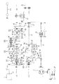
次に、図5乃至図7に基づいてトラクタTの動力伝達装置について説明する。 Next, the power transmission device for the tractor T will be described with reference to FIGS.
図5に示すように、前記エンジンEの回転動力は、メインクラッチ61を介してミッションケース1上部に支持したケース入力軸62によって同ケース内に入力される。前記ケース入力軸62は、ケース1の左右中心位置X−X上に設定され、この軸62後端部に入力ギヤ63を備えると共に、この入力ギヤ63の下方には、同入力ギヤ63と常時噛合わせる前ギヤ73fを有する中継軸73を支持する構成となっている。
As shown in FIG. 5, the rotational power of the engine E is input into the case by a
また前記中継軸73に支持する前ギヤ73fは、前記回転動力をケース1の左右一側に構成した走行系動力伝達装置L1と、左右他側に構成した作業機系動力伝達装置L2へ分岐する構成となっている。
Further, the
前記走行系動力伝達装置L1は、前記中継軸73に伝達された動力を、前ギヤ73fから、前後進変速部M1、第一主変速部M2、第二主変速部M3、及び副変速部M4等を経て後輪出力軸64へ伝達し、この出力軸64から、後輪デフ機構65を介して後輪2Rへ伝達すると共に、この出力軸64後部のギヤ66から後述するPTO連動軸67上に回転支持する前輪駆動力取出ギヤ68を介して、前輪増速部69、前輪駆動軸70、前輪デフ機構71、前輪2F等へと順に伝達する構成となっている。
The traveling system power transmission device L1 transmits the power transmitted to the
詳細に説明すると、前記前後進変速部M1は、前記中継軸73の前後ギヤ73f、73rと、前後進軸80上の前進ギヤ81と後進ギヤ82とを常時噛み合い式に構成し、前記前進ギヤ73fと後進ギヤ73r間に、湿式多板形態の前後進切替クラッチ83f、83rを備える構成となっている。また前記前後進軸80の近傍には、カウンター軸98を併設し、前記後ギヤ73rから後進ギヤ82へ伝わる回転動力を逆転させる構成となっている。
More specifically, the forward / reverse transmission portion M1 is configured such that the forward /
これにより、前記前後進切替クラッチ83f、83rの何れか一方を圧着操作することにより、伝動下手側の主変速駆動軸84を正転或いは逆転で駆動する。
As a result, one of the forward /
また前記第一主変速部M2は、4段変速式のシンクロメッシュギヤ式変速装置であり、前記主変速駆動軸84上に前後二つのシンクロクラッチ85a,85bによって選択する変速駆動ギヤ86(1速駆動ギヤ86a、2速駆動ギヤ86b、3速駆動ギヤ86c、4速駆動ギヤ86d)を空転支持し、これらの変速駆動軸84に併設した変速被駆動軸87上の各被駆動ギヤ(1速被駆動ギヤ87a、2速被駆動ギヤ87b、3速被駆動ギヤ87c、4速被駆動ギヤ87dを常時噛合させて構成する。
The first main transmission unit M2 is a four-speed transmission type synchromesh gear transmission, and a transmission gear 86 (first speed) selected by the front and rear two
尚、前記前後二つのシンクロクラッチ85a,85bは、別途備えた油圧シリンダのピストン伸縮操作にて前後移動させる構成となっている。
The two front and
また第二主変速部M3は、高低二段変速式の変速装置であり、前記変速被駆動軸87の後端に高低変速駆動軸88を支持し、同軸88上に湿式多板形態の高速クラッチ89h及び低速クラッチ89lを備える構成となっている。
The second main transmission unit M3 is a high / low two-stage transmission, which supports a high / low
これにより、前記両クラッチの内1つを圧着操作することで、前記高低変速駆動軸88と併設した高低変速被駆動軸92の各常時噛合ギヤを通じて副変速装置M4へ伝達する回転動力を、低/高に切り替える構成としている。
As a result, by pressing one of the clutches, the rotational power transmitted to the sub-transmission device M4 through the constantly meshing gears of the high / low speed driven
以上のように構成した前記第一、第二主変速装置M2,M3は全8段の変速を可能とし、前記変速レバー34の変速アップスイッチ34uと変速ダウンスイッチ34dの押し込み操作により別途備えたコントローラの通電により1段ずつアップダウンする構成となっている。
The first and second main transmissions M2 and M3 configured as described above are capable of shifting in all eight stages, and are separately provided by pressing the shift up
また前記副変速部M4は、前記変速レバー34の前後左右操作で切り替えられる3段変速式のコンスタントメッシュギヤ式変速装置であり、前記高低変速被駆動軸92の後端に、副変速被駆動軸94を支持し、前記高低変速被駆動軸92からの回転を、前後二つの副変速クラッチ96f,96rの前後操作によって後輪出力軸64へ伝達する構成となっている。
The sub-transmission unit M4 is a three-stage constant mesh gear type transmission that can be switched by front / rear / left / right operation of the
詳しくは、前記後輪出力軸64上に、二段ギヤを有する前カウンター軸95fと後カウンター軸95rを支持し、前記副変速被駆動軸94上に、前記前カウンター軸94fの回転を後カウンター軸95rへ伝達する中間カウンター91m軸と、前記後カウンター軸95rの回転を伝達する最終軸91を支持して、これら軸95f,91m,95r,91rを常時噛合ギヤにより一体回転すると共に、前記高低変速被駆動軸92の後端のギヤ93と、前記中間カウンター軸91mの前端のギヤ間に前記副変速前クラッチ96fを備え、中間カウンター軸91mの後端のギヤと最終軸91の前端のギヤ間に副変速後クラッチを備える構成となっている。そして、前記前記副変速前クラッチ96fを前方へ移動させて、3速とし、同クラッチ96rを後方へ移動させて2速とし、前記副変速後クラッチ96fを後方へ移動して1速とする構成となっている。
Specifically, a
以上のように構成したトラクタTでは、前後進変速部M1、第一主変速部M2、第二主変速部M3、副変速部M4のギヤの組み合わせにより、前後24段の変速位置を構成し、走行することができる。 In the tractor T configured as described above, the front / rear transmission gear portion M1, the first main transmission portion M2, the second main transmission portion M3, and the sub-transmission portion M4 are configured with a gear position of 24 stages in the front and rear. You can travel.
また作業機系動力伝達装置L2では、前記ミッションケース1前部の中継軸73に伝達された動力を前記前ギヤ73fから、PTOクラッチCpの駆動側ディスクと一体の常時噛合式ギヤ79へ伝達する構成となっている。そして、同回転動力は、前記PTOクラッチCpの入切操作によって被駆動側ディスクと一体のPTO連動軸75へ伝達、遮断操作する構成となっている。また前記PTO連動軸75には、前方から順に2速駆動ギヤ75b、4速駆動ギヤ75d、1速駆動ギヤ75a、3速駆動ギヤ75cの4つのPTO変速駆動ギヤを備えると共に、この内の一つのギヤを、同軸75と併設したPTO変速被駆動軸77上のPTO被駆動ギヤ77…の一つに噛み合わせる構成となっている。
In the work system power transmission device L2, the power transmitted to the
前記PTO被駆動軸77には、前方から順に2速被駆動ギヤ77r及び4速被駆動ギヤ77dを有する前クラッチ体76fと、1速ギヤ77a及び3速ギヤ77dを有する後クラッチ体76rを、後述する夫れ夫れシフタにより前後スライド自在に備える構成となっている。
The PTO driven
また更に、前記PTO連動軸75とPTO変速被駆動軸77近傍には、PTOカウンター軸78を併設し、同軸78上のPTOカウンターギヤ78rを、シフター操作により前後スライド自在に支持して逆転PTO機構Mpを構成している。
Further, a
これにより、前記PTO変速機構Mpでは、前記PTO連動軸75とPTO変速被駆動軸77上の各変速ギヤの内、一つを噛み合わせて正転4速の回転数を得ることができ、また前記二速駆動ギヤ75bと二速被駆動ギヤ77bへ伝達される回転を前記PTOカウンターギヤ78rを経由して伝達し、同回転数の逆転1速を得ることができる。
Thereby, in the PTO speed change mechanism Mp, one of the speed change gears on the
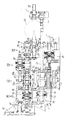
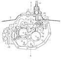
また前記走行系及び作業機系の各装置について図6と図7に基づいて説明すると、まずミッションケース1の上部で且つ仮想中心線(図7中のX−X線)上にケース入力軸62が支持され、この直下に前記中継軸73が支持される構成となっている。走行系動力伝達装置として、前記中継軸73の左右一側(図7中左側)に前記前後進軸80を支持し、この上方に前記前後進カウンター軸98を支持する構成となっている。また前記前後進軸80の後端部には、同一軸芯上に主変速軸84を支持し、同軸84と平行して変速被駆動軸87,高低変速駆動軸88を支持する構成となっている。
Further, the traveling system and the work machine system will be described with reference to FIGS. 6 and 7. First, the
一方、前記作業機系動力伝達装置として、前記中継軸73の左右他側(図9中右側)に、PTO連動軸75を支持し、同軸75と併設してPTO変速軸77とPTO逆転軸78を夫れ夫れ併設支持する構成となっている。
On the other hand, as the work machine system power transmission device, a
更に前記PTO連動軸75の後端部には、同一軸心上にPTO伝動軸67を支持し、この後部に前記前輪取出ギヤ68を回転自在に支持すると共に、後端部上方に常時噛合ギヤにより動力が伝達されるPTO軸29を支持する構成となっている。
Further, a
そして前記前後進切替クラッチ83f,83r、詳しくはこのクラッチ外形及び前後幅は、前記PTOクラッチCpの外形及び前後幅と前後位置及び上下高さを重複した位置に配置し、また第一主変速装置M2とPTO変速機構Mp、詳しくはギヤ外形及び前後両端に亘るギヤ支持幅も、前後幅及び上下高さを重複した位置に配置する構成となっている。
The forward /
また更に前記PTOカウンター軸78は、背面視前記中継軸73とPTO変速被駆動軸77の間に位置させ、前記第一主変速M2の前後幅及び上下高さを重複して配置する構成となっている
尚、前記図7中の符号120は、PTO変速部Mpを切り替えるPTO変速レバーを示し、前記ケース入力軸62の側方に併設支持した3本のシフター118a,118b,118cを、ガイド119に沿って前後左右に操作することで、PTO変速駆動軸77上の二つの変速クラッチ(PTO2速ギヤ76rとPTO1速ギヤ76aを有する前クラッチ75f,PTO3速ギヤ76cとPTO2速ギヤ76bを有する後クラッチ76r)及びPTOカウンター軸78上の逆転クラッチ78cを選択して前後に操作する構成となっている。
Further, the
また前記PTO変速レバー120は、前記ハンドルポスト22下方の空間で前後左右に操作する構成となっており、このボール支持部を中心に背面視「く」の字状に屈曲させて、下部のシフターアーム部120aを前記入力ギヤ63の側方に突設する構成となっている。そして同シフターアーム120aを、前記ケース上部コーナ部に集中配置した前記3本のシフタの一つに係止して同シフタを前後方向に操作する構成となっている。
The PTO
また符合122a,122bは、第一変速装置M2を切り替えるシフターを示し、前記シンクロクラッチ85a,85bを夫れ夫れ挟持して、前記変速アップスイッチとダウンスイッチの押し込み操作に連動して制御弁123が切り替えられて操作される。
Reference numerals 122a and 122b denote shifters for switching the first transmission M2, and the
以上のように構成したトラクタTの伝動装置では、前記中継軸73に対して前記ミッションケース1の左右一側に走行系動力伝達装置L1を配置し、左右他側に、作業機系動力伝達装置L2を構成するPTO連動軸75を支持すると共に、同軸75上で、且つ側面視前記前後進切替クラッチ83f、83rの高さ及び前後幅を重複させて前記中継軸73からの動力を入切操作する前記動力伝達クラッチCpを構成したので、特にミッションケース1前部の上下幅及び前後幅を短縮することができトラクタTのフロア6前部スペースを広く設定することができ、或いはトラクタ全体をコンパクトに構成することができる。
In the transmission device of the tractor T configured as described above, the traveling system power transmission device L1 is disposed on the left and right sides of the
また前記作業機系動力伝達装置L2を構成するPTO連動軸75の延長上に、PTO変速ギヤ74…を支持し、これを併設するPTO変速被駆動軸77上のギヤ76…とでPTO変速部Mpを構成し、同変速部Mpを前記第一主変速部(M2)との高さ及び前後幅を重複させて構成したので、特にミッションケース1中間部の上下幅及び前後幅を短縮することができてトラクタTのフロア6前後中間部のスペースを広く設定することができ、或いはトラクタT全体をコンパクトに構成することができる。
Further, a PTO transmission gear 74 is supported on an extension of the
また前記PTO変速装置Mpには、前記ミッションケース1の左右他側で且つ前記変速被駆動軸77と略同高さに、前記PTO変速駆動軸75からPTO変速被駆動軸77への動力回転方向を逆転して伝達するPTOカウンター軸78を備えたので、前記PTO変速機構Mpに逆転PTO機構を構成する場合でも、前記同様ミッションケース1中間部の上下幅及び前後幅を短縮することができて、ひいてはトラクタ全体をコンパクトに構成することができる。また、前記逆転PTO機構をミッションケース1の他の個所に備える場合と比較して、逆転PTO機構を切換操作するシフタ118…及びこれを支持するシフタ支持軸121a,121b,121cをケースコーナ部に集中配置することができるので、生産組付時やメンテナンス時の組付性を向上し工数を省力化することができる。更にPTO軸29の回転を操作するレバー120の操作面においても、単一のPTO変速レバー120で略同一の操作ストロークで変速及び逆転に切替操作することができて、操作性を向上するとができる。
The PTO transmission Mp includes a rotational direction of power from the PTO
次に前記発明の他の形態について説明する。 Next, another embodiment of the invention will be described.
図8に示すトラクタTでは、前記前記3段変速式の副変速装置M4に代えて、高低二段を有するコンスタントメッシュギヤ式副変速装置M4’を構成したものである。 In the tractor T shown in FIG. 8, a constant mesh gear type sub-transmission M4 'having two levels of high and low is used instead of the three-stage sub-transmission M4.
ここでは、前記副変速被駆動軸94上に単一のクラッチ96fを設け、同クラッチの前後操作で前記高低変速被駆動軸92と一体回転するギヤ93に直結するか、或いは前記クラッチ95fを迂回させて回転数を落とした後部ギヤに噛み合わせるかを選択し、伝達された回転を副変速被駆動ギヤ94から前記後輪出力軸64へ常時噛合ギヤを介して伝達する構成となっている。
Here, a single clutch 96f is provided on the auxiliary transmission driven
これにより、常時噛み合いギヤの被駆動側ギヤを前記64に一体回転自在に支持し、トラクタの副変速位置を削減して安価に構成することができる。 As a result, the driven gear of the constantly meshing gear is supported by the 64 so as to be integrally rotatable, and the sub-shift position of the tractor can be reduced and the construction can be made at low cost.
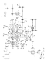
また図9に示すトラクタTでは、前記コントローラの操作で切り替える第一主変速装置M2及び第二主変速装置M3の代わりに、コンスタントメッシュギヤ式の主変速装置M2’を構成すると共に、前記3段変速式の副変速装置M4を4段式に構成したものである。 Further, in the tractor T shown in FIG. 9, instead of the first main transmission M2 and the second main transmission M3 that are switched by the operation of the controller, a constant mesh gear type main transmission M2 ′ is configured, and the three-stage The transmission-type subtransmission device M4 is configured in a four-stage system.
詳しくは前記前後進軸80の後端に常時噛合ギヤ126を設け、この後端部同一軸芯上に主変速被駆動軸84を支持すると共に、同軸84と平行して主変速駆動軸87を支持する構成となっている。また前記主変速駆動軸87と前記主変速被駆動軸84との間には、前方から順に3速ギヤ組127a、2速ギヤ組127b、1速ギヤ組127cを備える構成となっている。また更に、前記主変速被駆動軸84には、前後二つのクラッチ130f,130rをスライド自在に支持し、両クラッチの内の1つを主変速レバー128により前後操作して、主変速駆動軸87の回転を主変速被駆動軸84へ伝達する構成となっている。即ち、前記前クラッチ130fを前方へ移動すると、前記前後進軸80と主変速被駆動軸84が直結されて第4速となり、前クラッチ130fを後方へ移動すると第3速となり、前記後クラッチ130rを前方へ移動すると第2速となり、後クラッチ130rを後方へ移動すると第1速となる。
Specifically, a
また前記主変速被駆動軸84の後端部同一軸芯上には、副変速第一駆動軸131aを設け、前記主変速駆動軸87の後端部同一軸芯上には、副変速第二駆動軸131bを設けると共に、同軸131b上に前カウンター軸132fと後カウンター軸132rを回転自在に支持する構成となっている。また前記副変速第一駆動軸の中間部には、前記前カウンター軸132fからの回転を後カウンター軸12rへ常時伝達する中継カウンター軸133を回転自在に支持する構成となっている。また前記副変速第一駆動軸131aには、副変速前クラッチ134fをスライド自在に支持し、副変速第二駆動軸131bには副変速後クラッチ134rをスライド自在に支持する構成となっている。
A sub-transmission
これにより、前記別途備えた副変速レバー135により前クラッチ134fを前方に移動させて、主変速被駆動軸84と副変速第一駆動軸131aを直結させて第4速とし、前クラッチ134fを後方へ移動させて中間カウンター軸133前端部のギヤと副変速第一駆動軸131aを連結して第3速とし、更に後クラッチ134rを後方へ移動させて、前カウンター軸132fと副変速第二駆動軸131bを連結して第2速とし、後クラッチ134rを後方へ移動して後カウンター軸132rと副変速第二駆動軸131bとを連結して第1速とすることができる。
Accordingly, the front clutch 134f is moved forward by the separately-provided auxiliary transmission lever 135, the main transmission driven
これにより、主変速と副変速の組み合わせにより全16段の変速を得ることができる。また前記コントローラの操作で切り替える第一主変速装置M2及び第二主変速装置M3を備える構成と比較して、安価に構成することができる。 As a result, a total of 16 shifts can be obtained by combining the main shift and the sub-shift. Further, it can be configured at a lower cost compared to the configuration including the first main transmission M2 and the second main transmission M3 that are switched by the operation of the controller.
CpPTOクラッチ(作業機系動力伝達入切クラッチ)
E エンジン(E)
M1 前後進切替部
M2 第一走行変速部
M3 第二主変速装置
M4 副変速装置
Mp PTO変速部
1 ミッションケース
2F前輪
2R後輪
29 PTO軸
62 ケース入力軸
75 PTO系伝動軸
77 前記変速被駆動軸
78 PTOカウンター軸
83 前後進切替クラッチ
CpPTO clutch (work machine power transmission on / off clutch)
E Engine (E)
M1 Forward / reverse switching unit M2 First traveling transmission unit M3 Second main transmission M4 Sub transmission Mp
Claims (3)
前記ミッションケース(1)の左右略中心部(X−X)に、前記エンジン(E)からの動力を入力するケース入力軸(62)と、同軸(62)と常時噛合ギヤ(63,73f)を介して駆動される中継軸(73)を支持し、
前記中継軸(73)に対して前記ミッションケース(1)の左右一側に、走行系動力伝達装置を構成する走行系伝動軸(80)を支持すると共に、同軸(80)上に前記中継軸(73)からの動力回転方向を正逆切り替える前記前後進切替部(M1)の前後進切替クラッチ(83f、83r)を備える一方、
前記中継軸(73)に対して前記ミッションケース(1)の左右他側に、PTO系動力伝達装置を構成するPTO系伝動軸(75)を支持すると共に、同軸(75)上に、且つ側面視前記前後進切替クラッチ(83f、83r)の高さ及び前後幅を重複させて前記中継軸(73)からの動力を入切操作する前記作業機系動力伝達クラッチ(Cp)を構成したことを特徴とする作業車両の動力伝達装置。 Rotational power of the engine (E) is input into the mission case (1), and the traveling system power having the forward / reverse switching part (M1) and the traveling speed change parts (M2 to M4) provided in the case (1). The power is transmitted to the drive wheels (2F, 2R) via the transmission device, and the power is transmitted to the PTO via the work implement power transmission device having a work implement power transmission on / off clutch (Cp) and a PTO transmission (Mp). In the power transmission device of the work vehicle that transmits to the shaft (29),
A case input shaft (62) for inputting power from the engine (E), a coaxial (62), and a constant meshing gear (63, 73f) to the left and right center (XX) of the transmission case (1) Supporting the relay shaft (73) driven through
On the left and right sides of the transmission case (1) with respect to the relay shaft (73), a traveling system transmission shaft (80) constituting a traveling system power transmission device is supported, and the relay shaft is coaxially mounted on the relay shaft (80). While including the forward / reverse switching clutch (83f, 83r) of the forward / reverse switching section (M1) for switching the power rotation direction from (73) forward and reverse,
A PTO system transmission shaft (75) constituting a PTO system power transmission device is supported on the left and right other sides of the transmission case (1) with respect to the relay shaft (73), on the same axis (75), and on the side surface. As a result, the work machine power transmission clutch (Cp) configured to turn on / off the power from the relay shaft (73) by overlapping the height and the front / rear width of the forward / reverse switching clutch (83f, 83r). A power transmission device for a working vehicle.
前記作業機系動力伝達装置を構成するPTO系伝動軸(75)の延長上に、前記走行変速部(M2)の高さ及び前後幅を重複させてPTO変速ギヤ(74a,74b…)を支持してPTO変速部(Mp)を構成したことと特徴とする請求項1に記載の作業車両の動力伝達装置。 A travel transmission unit (M2) is supported by supporting the travel transmission drive shaft (84) or the travel transmission driven shaft (87) on a coaxial core extension of the travel system transmission shaft (80) constituting the travel system power transmission device. As well as
The PTO transmission gears (74a, 74b,...) Are supported on the extension of the PTO transmission shaft (75) constituting the work machine power transmission device by overlapping the height and the front-rear width of the traveling transmission unit (M2). The power transmission device for a work vehicle according to claim 1, wherein a PTO transmission unit (Mp) is configured.
Priority Applications (1)
| Application Number | Priority Date | Filing Date | Title |
|---|---|---|---|
| JP2004115558A JP2005297710A (en) | 2004-04-09 | 2004-04-09 | Power transmission device for work vehicle |
Applications Claiming Priority (1)
| Application Number | Priority Date | Filing Date | Title |
|---|---|---|---|
| JP2004115558A JP2005297710A (en) | 2004-04-09 | 2004-04-09 | Power transmission device for work vehicle |
Publications (1)
| Publication Number | Publication Date |
|---|---|
| JP2005297710A true JP2005297710A (en) | 2005-10-27 |
Family
ID=35329790
Family Applications (1)
| Application Number | Title | Priority Date | Filing Date |
|---|---|---|---|
| JP2004115558A Pending JP2005297710A (en) | 2004-04-09 | 2004-04-09 | Power transmission device for work vehicle |
Country Status (1)
| Country | Link |
|---|---|
| JP (1) | JP2005297710A (en) |
Cited By (7)
| Publication number | Priority date | Publication date | Assignee | Title |
|---|---|---|---|---|
| KR100751207B1 (en) | 2006-03-03 | 2007-08-22 | 엘에스전선 주식회사 | Transmission for tractor |
| JP2008095748A (en) * | 2006-10-06 | 2008-04-24 | Yanmar Co Ltd | Transmission |
| JP2009208552A (en) * | 2008-03-03 | 2009-09-17 | Mitsubishi Agricult Mach Co Ltd | Tractor |
| JP2012001145A (en) * | 2010-06-18 | 2012-01-05 | Kubota Corp | Tractor |
| JP2012001146A (en) * | 2010-06-18 | 2012-01-05 | Kubota Corp | Tractor |
| EP2708774A1 (en) * | 2012-09-14 | 2014-03-19 | Iseki & Co., Ltd. | Working vehicle |
| JP2014166801A (en) * | 2013-02-28 | 2014-09-11 | Iseki & Co Ltd | Work vehicle |
-
2004
- 2004-04-09 JP JP2004115558A patent/JP2005297710A/en active Pending
Cited By (9)
| Publication number | Priority date | Publication date | Assignee | Title |
|---|---|---|---|---|
| KR100751207B1 (en) | 2006-03-03 | 2007-08-22 | 엘에스전선 주식회사 | Transmission for tractor |
| JP2008095748A (en) * | 2006-10-06 | 2008-04-24 | Yanmar Co Ltd | Transmission |
| JP2009208552A (en) * | 2008-03-03 | 2009-09-17 | Mitsubishi Agricult Mach Co Ltd | Tractor |
| JP2012001145A (en) * | 2010-06-18 | 2012-01-05 | Kubota Corp | Tractor |
| JP2012001146A (en) * | 2010-06-18 | 2012-01-05 | Kubota Corp | Tractor |
| EP2708774A1 (en) * | 2012-09-14 | 2014-03-19 | Iseki & Co., Ltd. | Working vehicle |
| JP2014058194A (en) * | 2012-09-14 | 2014-04-03 | Iseki & Co Ltd | Work vehicle |
| US9003908B2 (en) | 2012-09-14 | 2015-04-14 | Iseki & Co., Ltd. | Working vehicle |
| JP2014166801A (en) * | 2013-02-28 | 2014-09-11 | Iseki & Co Ltd | Work vehicle |
Similar Documents
| Publication | Publication Date | Title |
|---|---|---|
| US5913950A (en) | Transmission for a working vehicle | |
| US5937697A (en) | Power take-off assembly for tractors | |
| JP4958683B2 (en) | Work vehicle | |
| TWI594912B (en) | Work vehicle | |
| JP2009214818A (en) | Work vehicle | |
| JP2005297710A (en) | Power transmission device for work vehicle | |
| JP4934541B2 (en) | Work vehicle | |
| JP2017036773A (en) | Auxiliary shifting device and work vehicle equipped with the same | |
| JP5095849B1 (en) | Work vehicle transmission | |
| JP6155701B2 (en) | Work vehicle | |
| JP5207787B2 (en) | Work vehicle | |
| JP4351895B2 (en) | Four-wheel drive vehicle | |
| JP3727218B2 (en) | Tractor transmission structure | |
| JP2022047238A (en) | Working vehicle | |
| JP4292339B2 (en) | Tractor | |
| JP4166108B2 (en) | Work vehicle | |
| JP2005162006A (en) | Transmission | |
| JP4958682B2 (en) | Work vehicle | |
| JP4996358B2 (en) | Transmission device for passenger vehicle | |
| JP5003751B2 (en) | Shift control device for work vehicle | |
| JP4953375B2 (en) | Work vehicle | |
| JPS6238853Y2 (en) | ||
| JPS6315616Y2 (en) | ||
| JPS6225930Y2 (en) | ||
| JP4666128B2 (en) | Shift control device for work vehicle |