JP2005297633A - Vehicle seat device - Google Patents

Vehicle seat device Download PDF

Info

Publication number
JP2005297633A
JP2005297633A JP2004113235A JP2004113235A JP2005297633A JP 2005297633 A JP2005297633 A JP 2005297633A JP 2004113235 A JP2004113235 A JP 2004113235A JP 2004113235 A JP2004113235 A JP 2004113235A JP 2005297633 A JP2005297633 A JP 2005297633A
Authority
JP
Japan
Prior art keywords
divided body
seat
cushion
tray
cup holder
Prior art date
Legal status (The legal status is an assumption and is not a legal conclusion. Google has not performed a legal analysis and makes no representation as to the accuracy of the status listed.)
Granted
Application number
JP2004113235A
Other languages
Japanese (ja)
Other versions
JP4060285B2 (en
Inventor
Shinsuke Watanabe
晋介 渡辺
Takahiro Ito
隆裕 伊藤
Osuke Koike
欧介 小池
Taku Roppongi
卓 六本木
Current Assignee (The listed assignees may be inaccurate. Google has not performed a legal analysis and makes no representation or warranty as to the accuracy of the list.)
Honda Motor Co Ltd
Original Assignee
Honda Motor Co Ltd
Priority date (The priority date is an assumption and is not a legal conclusion. Google has not performed a legal analysis and makes no representation as to the accuracy of the date listed.)
Filing date
Publication date
Application filed by Honda Motor Co Ltd filed Critical Honda Motor Co Ltd
Priority to JP2004113235A priority Critical patent/JP4060285B2/en
Publication of JP2005297633A publication Critical patent/JP2005297633A/en
Application granted granted Critical
Publication of JP4060285B2 publication Critical patent/JP4060285B2/en
Anticipated expiration legal-status Critical
Expired - Fee Related legal-status Critical Current

Links

Images

Landscapes

  • Passenger Equipment (AREA)

Abstract

<P>PROBLEM TO BE SOLVED: To provide a vehicular seat device in which an article can be stably loaded on a seat without any occupant seating therein. <P>SOLUTION: A front side portion of a seat cushion 17 is inverted around a front end side to form a table part 53 provided on a back face 40b as an upwardly arranged front side split body 40. A cushion tray 48 is provided facing a back side 40b when the front side split body 40 is accommodated. An upper face part 58 having a cup holder part 61 is formed on the back face 40b side of the front side split body 40, and the upper face part 58 is abutted on a cushion tray 48 when the front side split body 40 is accommodated. <P>COPYRIGHT: (C)2006,JPO&NCIPI

Description

本発明は、車両用シート装置に関する。   The present invention relates to a vehicle seat device.

車両用シート装置に関する技術として、例えば、乗員が乗車しないシートのシートクッションの中央側の一部を取り外すことで、物品を安定的に載置可能な載置部を形成したり、この載置部の開口を開閉可能な蓋体を設けたりするものがある(例えば、特許文献1参照)。
実開平2−220936号公報
As a technique related to the vehicle seat device, for example, by removing a part of the center side of the seat cushion of a seat on which an occupant does not get on, a placement portion on which an article can be stably placed is formed, or this placement portion There is a thing which provides the cover body which can open and close this opening (for example, refer patent document 1).
Japanese Utility Model Publication No. 2-220936

上記のようにシートクッションの中央側の一部を取り外すことで載置部を形成するのでは、物品を安定的に置くためにシートクッションの一部を一々取り外さなければならず、非常に手間がかかってしまう。   As described above, when the placement portion is formed by removing a part of the center side of the seat cushion, a part of the seat cushion must be removed one by one in order to stably place the article, which is very troublesome. It will take.

したがって、本発明は、乗員が乗車しないシートに対し物品を安定的に載置させることが容易に可能となる車両用シート構造の提供を目的とする。   Accordingly, an object of the present invention is to provide a vehicle seat structure in which an article can be easily placed stably on a seat on which an occupant does not get on.

上記目的を達成するために、請求項1に係る発明は、シートクッション(例えば実施形態におけるシートクッション17)の前側部分が前端側を中心に反転することで裏面(例えば実施形態における裏面40b)に設けられたテーブル部(例えば実施形態におけるテーブル部53)を上向きに配置する前側分割体(例えば実施形態における前側分割体40)とされ、該前側分割体の収納時の前記裏面に対向してクッショントレー(例えば実施形態におけるクッショントレー48)が設けられ、前記前側分割体の前記裏面側にカップホルダ部(例えば実施形態におけるカップホルダ部61)を有する上面部(例えば実施形態における上面部58)を形成するとともに、前記前側分割体の収納時に前記上面部を前記クッショントレーに当接させることを特徴としている。   In order to achieve the above object, the invention according to claim 1 is directed to the back surface (for example, the back surface 40b in the embodiment) by reversing the front portion of the seat cushion (for example, the seat cushion 17 in the embodiment) around the front end side. A front divided body (for example, the front divided body 40 in the embodiment) in which the provided table section (for example, the table section 53 in the embodiment) is disposed upward is cushioned against the back surface when the front divided body is stored. A tray (for example, the cushion tray 48 in the embodiment) is provided, and an upper surface portion (for example, the upper surface portion 58 in the embodiment) having a cup holder portion (for example, the cup holder portion 61 in the embodiment) on the back surface side of the front divided body. And the upper surface portion is brought into contact with the cushion tray when the front divided body is stored. It is characterized by a door.

請求項2に係る発明は、請求項1に係る発明において、前記カップホルダ部が筒状をなしていることを特徴としている。   The invention according to claim 2 is characterized in that, in the invention according to claim 1, the cup holder portion has a cylindrical shape.

請求項3に係る発明は、請求項1または2に係る発明において、前記クッショントレーの下方に引き出し式の収納ボックス(例えば実施形態における収納ボックス69)が設けられていることを特徴としている。   The invention according to claim 3 is the invention according to claim 1 or 2, characterized in that a drawer-type storage box (for example, the storage box 69 in the embodiment) is provided below the cushion tray.

請求項1に係る発明によれば、シートクッションの前側部分の前側分割体をその前端側を中心に反転させると裏面に設けられたテーブル部が上向きに配置されることになり、また、前側分割体の収納時の裏面に対向して設けられたクッショントレーが上向きに露出する。これにより、これらテーブル部およびクッショントレーに安定的に物品を載置させることができることから、乗員が乗車しないシートに対し物品を安定的に載置させることが容易に可能となる。また、前側分割体の裏面側のカップホルダ部を有する上面部が前側分割体の収納時にクッショントレーに当接する位置つまり反転状態で高さが高くなる位置に配置されていることから、カップホルダ部の深さを深くでき、その結果、飲料容器を安定的に載置させることができる。さらに、前側分割体の収納時にカップホルダ部が形成された上面部がクッショントレーに当接するため、前側分割体を下側から確実に支えることができ、その結果、乗員の着席時の座り心地を損なうことがない。   According to the first aspect of the present invention, when the front divided body of the front portion of the seat cushion is inverted about the front end side, the table portion provided on the back surface is disposed upward, and the front divided A cushion tray provided facing the back surface when the body is stored is exposed upward. Thereby, since articles can be stably placed on the table portion and the cushion tray, it is possible to easily place articles on a seat on which an occupant does not get on. In addition, since the upper surface portion having the cup holder portion on the back surface side of the front divided body is disposed at a position where it comes into contact with the cushion tray when the front divided body is stored, that is, at a position where the height is increased in the inverted state. Can be deepened, and as a result, the beverage container can be stably placed. Furthermore, since the upper surface portion on which the cup holder portion is formed abuts against the cushion tray when the front divided body is stored, the front divided body can be reliably supported from the lower side. There is no loss.

請求項2に係る発明によれば、カップホルダ部が筒状をなしていることから、収納時にカップホルダ部が形成された上面部においてクッショントレーに当接する前側分割体の下部の剛性を高めることができ、その結果、座り心地をさらに良好にすることができる。   According to the invention which concerns on Claim 2, since the cup holder part has comprised the cylinder shape, the rigidity of the lower part of the front side division body which contact | abuts a cushion tray in the upper surface part in which the cup holder part was formed at the time of accommodation is improved. As a result, the sitting comfort can be further improved.

請求項3に係る発明によれば、クッショントレーの下方に引き出し式の収納ボックスが設けられているため、物品の収納を良好に行うことができる。しかも引き出し式であることから収納物を露出させずに収納できる。   According to the invention of claim 3, since the drawer-type storage box is provided below the cushion tray, the article can be stored satisfactorily. Moreover, since it is a drawer type, it can be stored without exposing the stored items.

本発明の一実施形態の車両用シート装置を図面を参照して以下に説明する。なお、以下の説明において用いる前後左右は車体における前後左右である。   A vehicle seat device according to an embodiment of the present invention will be described below with reference to the drawings. Note that the front, rear, left and right used in the following description are front, rear, left and right in the vehicle body.

本実施形態の車両用シート装置は、左右両側に配置される一対の側部シートと、これら側部シートの間に配置される中央シートとを有する三人掛けの構造であり、前後方向の二列のうちの前列の中央シートに適用されている。なお、いずれのシートにも適用可能である。   The vehicle seat device of the present embodiment has a three-seat structure having a pair of side seats arranged on the left and right sides and a center seat arranged between the side seats. Applied to the center sheet of the front row of rows. It can be applied to any sheet.

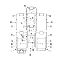
図1に示すように、前から一列目の左右一対の側部シート11は、それぞれ、シートクッション12とシートバック13とを有しており、それぞれ単独で、シートクッション12の下側に設けられたスライド機構14によって前後スライド可能となっている。なお、これら側部シート11はスライド機構14による前後スライドの範囲が互いに一致している。   As shown in FIG. 1, the pair of left and right side seats 11 in the first row from the front have a seat cushion 12 and a seat back 13, respectively, and are each provided below the seat cushion 12. The slide mechanism 14 can slide back and forth. Note that these side seats 11 have the same range of front and rear slides by the slide mechanism 14.

中央シート16は、シートクッション17とシートバック18とを有しており、シートクッション17の下側に設けられたスライド機構19によって単独で前後スライド可能となっている。なお、中央シート16はスライド機構19による前後スライドの範囲が側部シート11のスライド機構14によるスライド範囲に対し一部重なり合いながら後側に所定量ずれている。また、中央シート16のスライド機構19によるスライド範囲は、側部シート11のスライド機構14によるスライド範囲よりも大きく設定されている。   The central seat 16 has a seat cushion 17 and a seat back 18, and can be slid back and forth independently by a slide mechanism 19 provided on the lower side of the seat cushion 17. The center seat 16 is shifted by a predetermined amount to the rear side while the range of the front and rear slide by the slide mechanism 19 partially overlaps the slide range of the side seat 11 by the slide mechanism 14. The slide range of the central seat 16 by the slide mechanism 19 is set larger than the slide range of the side seat 11 by the slide mechanism 14.

具体的には、図1に二点鎖線で示すように、一対の側部シート11をスライド機構14により前端位置に位置させるとともに中央シート16をスライド機構19により前端位置に位置させると、一対の側部シート11よりも中央シート16が所定量後側にずれることになり、V字レイアウトとなる。   Specifically, as shown by a two-dot chain line in FIG. 1, when the pair of side sheets 11 is positioned at the front end position by the slide mechanism 14 and the center sheet 16 is positioned at the front end position by the slide mechanism 19, The center sheet 16 is shifted to the rear side by a predetermined amount with respect to the side sheet 11, resulting in a V-shaped layout.

また、図1に実線で示すように両側の側部シート11をスライド機構14により後端位置に位置させるとともに、図1に二点鎖線で示すように中央シート16をスライド機構19により前端位置に位置させると、図2にも示すように、両側の側部シート11と中央シート16とが前後に位置を合わせる直線状のレイアウトになる。   Further, the side sheets 11 on both sides are positioned at the rear end position by the slide mechanism 14 as shown by the solid line in FIG. 1, and the center sheet 16 is moved to the front end position by the slide mechanism 19 as shown by the two-dot chain line in FIG. When positioned, as shown also in FIG. 2, the side sheet 11 and the center sheet 16 on both sides have a linear layout that aligns the front and rear positions.

さらに、図1に二点鎖線で示すように両側の側部シート11をスライド機構14により前端位置に位置させるとともに、図1に実線で示すように中央シート16をスライド機構19により後端位置に位置させると、一対の側部シート11よりも中央シート16が所定量後側にずれることになり、V字レイアウトとなる。   Further, the side sheets 11 on both sides are positioned at the front end position by the slide mechanism 14 as shown by a two-dot chain line in FIG. 1, and the center sheet 16 is moved to the rear end position by the slide mechanism 19 as shown by a solid line in FIG. When positioned, the center sheet 16 is shifted to the rear side by a predetermined amount from the pair of side sheets 11, resulting in a V-shaped layout.

加えて、図1に実線で示すように、両側の側部シート11をスライド機構14により後端位置に位置させるとともに中央シート16をスライド機構19により後端位置に位置させると、図3にも示すように、一対の側部シート11よりも中央シート16が所定量後側にずれることになり、V字レイアウトとなる。   In addition, as shown by a solid line in FIG. 1, when the side sheets 11 on both sides are positioned at the rear end position by the slide mechanism 14 and the center sheet 16 is positioned at the rear end position by the slide mechanism 19, FIG. As shown in the figure, the center sheet 16 is shifted to the rear side by a predetermined amount from the pair of side sheets 11, resulting in a V-shaped layout.

前から二列目の左右一対の側部シート21は、それぞれ、シートクッション22とシートバック23とを有しており、前後スライド不可となっている。   The pair of left and right side seats 21 in the second row from the front have a seat cushion 22 and a seat back 23, respectively, and are not slidable back and forth.

二列目の両側部シート21の間に設けられる中央シート26は、シートクッション27とシートバック28とを有しており、シートクッション27の下側に設けられたスライド機構29によって単独で前後スライド可能となっている。なお、中央シート26はスライド機構29による前後スライドの範囲が位置固定の側部シート21から後側に延びている。   The central seat 26 provided between the two side seats 21 in the second row has a seat cushion 27 and a seat back 28, and slides back and forth independently by a slide mechanism 29 provided below the seat cushion 27. It is possible. The center seat 26 extends rearward from the side seat 21 whose position is fixed by the slide mechanism 29 in the longitudinal direction.

具体的には、図1に二点鎖線で示すように、中央シート26をスライド機構29により前端位置に位置させると、図2にも示すように、両側の側部シート21と中央シート26とが前後に位置を合わせる直線状のレイアウトになる。   Specifically, as shown by a two-dot chain line in FIG. 1, when the center sheet 26 is positioned at the front end position by the slide mechanism 29, as shown in FIG. Becomes a linear layout that aligns the front and back.

また、図1に実線で示すように、中央シート26をスライド機構29により後端位置に位置させると、一対の側部シート21よりも中央シート26が所定量後側にずれることになり、図3にも示すように、V字レイアウトとなる。   Further, as shown by a solid line in FIG. 1, when the center sheet 26 is positioned at the rear end position by the slide mechanism 29, the center sheet 26 is shifted to the rear side by a predetermined amount from the pair of side sheets 21. As shown in FIG.

次に、一列目の中央シート16についてさらに説明する。   Next, the center sheet 16 in the first row will be further described.

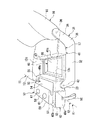
一列目の中央シート16は、図4および図5に示すように、そのシートフレーム31においてスライド機構19に支持されており、シートフレーム31は、前後方向に沿う下部延在部32と下部延在部32の前端部から上方に突出する前部上方突出部33と下部延在部32の後端部から上方に延出する後部上方延出部34とを備えた一対の側部フレーム35を有している。中央シート16のシートバック18は、下部側が左右方向に沿う軸線を中心として回動可能となるように側部フレーム35の後部上方延出部34の上部に支持軸36を介して支持されている。   As shown in FIGS. 4 and 5, the center seat 16 in the first row is supported by the slide mechanism 19 in the seat frame 31. The seat frame 31 includes a lower extension portion 32 and a lower extension extending in the front-rear direction. A pair of side frames 35 having a front upper projecting portion 33 projecting upward from the front end portion of the portion 32 and a rear upper extending portion 34 extending upward from the rear end portion of the lower extending portion 32; doing. The seat back 18 of the central seat 16 is supported on the upper part of the rear upper extension 34 of the side frame 35 via a support shaft 36 so that the lower side can be rotated about an axis extending in the left-right direction. .

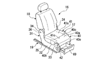
この中央シート16のシートクッション17は、図6にも示すように、前側分割体40と後側分割体41とに分割されている。後側分割体41は、略直方体形状をなしており、側部フレーム35の下部延在部32の後部側に車幅方向の両端側が載置されるようにしてシートフレーム31に固定されている。   The seat cushion 17 of the central seat 16 is divided into a front divided body 40 and a rear divided body 41 as shown in FIG. The rear divided body 41 has a substantially rectangular parallelepiped shape, and is fixed to the seat frame 31 so that both ends in the vehicle width direction are placed on the rear side of the lower extension portion 32 of the side frame 35. .

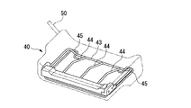
前側分割体40は、左右方向に沿う軸線を中心として回動可能となるように側部フレーム35の前部上方突出部33の上部に支持軸42を介して支持されている。なお、図7に示すように前側分割体40内にはクッションフレーム43が設けられており、このクッションフレーム43において前側分割体40は支持軸42に軸支されている。クッションフレーム43には複数のクッションワイヤ44が左右方向の中間位置に設けられており、左右方向の両端側にテーブルワイヤ45が設けられている。   The front divided body 40 is supported via a support shaft 42 on the upper part of the front upper protrusion 33 of the side frame 35 so as to be rotatable about an axis along the left-right direction. As shown in FIG. 7, a cushion frame 43 is provided in the front divided body 40, and the front divided body 40 is pivotally supported by the support shaft 42 in the cushion frame 43. The cushion frame 43 is provided with a plurality of cushion wires 44 at intermediate positions in the left-right direction, and table wires 45 are provided at both ends in the left-right direction.

前側分割体40は、略直方体形状をなしており、図4に示すように、座面40aを上側にした状態で、裏面40bの後端側の左右方向における両端部がシートフレーム31の下部延在部32に載置され、裏面40b側の左右方向の中間部が側部フレーム35間に架設されたクッショントレー48に載置されるようになっている。   The front divided body 40 has a substantially rectangular parallelepiped shape, and as shown in FIG. 4, both ends in the left-right direction on the rear end side of the back surface 40 b extend below the seat frame 31 with the seating surface 40 a facing upward. The intermediate part of the left-right direction by the side of the back surface 40b is mounted in the cushion tray 48 erected between the side frames 35.

ここで、座面40aを上側にした収納状態で、前側分割体40は、その後側の面40cを後側分割体41の前面41cに隙間なく接触させるとともに、後側分割体41の座面41aと自らの座面40aとをほぼ連続させる状態となる。つまり、前側分割体40がこの収納状態にあるときシートクッション17は乗員の着席を可能とする。   Here, in the stored state with the seating surface 40a facing upward, the front divided body 40 brings the rear surface 40c into contact with the front surface 41c of the rear divided body 41 without any gap, and also the seating surface 41a of the rear divided body 41. And its own seating surface 40a are almost continuous. That is, when the front divided body 40 is in the stored state, the seat cushion 17 enables a passenger to sit.

前側分割体40は、上記収納状態における前端側の側部が支持軸42によって側部フレーム35の前部上方突出部33の上部に回動可能に支持されており、この収納状態で支持軸42よりも後側の側面40dに回転可能に支持されたストラップ50を引き上げると、前側分割体40は、後端側が引き上げられて、支持軸42すなわち左右方向に沿う軸線を中心に前方へ回動することになる。そして、前側分割体40は、回動により座面40aを下方に向け裏面40bを上向きするように上下反転した状態で、図示せぬストッパに当接してそれ以上の回動が規制される。この状態が前側分割体40の回動状態である。   The front divided body 40 is supported by the support shaft 42 so that the side portion on the front end side in the above-described storage state is pivotable on the upper part of the front upper protrusion 33 of the side frame 35, and in this storage state, the support shaft 42. When the strap 50 rotatably supported on the side surface 40d on the rear side is pulled up, the front-side divided body 40 is pulled up on the rear end side and rotated forward about the support shaft 42, that is, the axis line along the left-right direction. It will be. Then, the front-side divided body 40 abuts against a stopper (not shown) in a state where the front-side divided body 40 is turned upside down so that the seating surface 40a faces downward and the back surface 40b faces upward. This state is the rotating state of the front divided body 40.

回動状態にある上下反転後の前側分割体40の裏面40bつまり上面側には、合成樹脂製のテーブル部材52が上記したクッションフレーム43のテーブルワイヤ45に支持された状態で固定されている(支持構造は図示略)。このテーブル部材52は、回動状態にある前側分割体40の上面側の後部にテーブル部53を有しており、このテーブル部53は、この状態で水平に配置される底面部54とこの底面部54の周縁部から若干立ち上がる囲壁部55とを有していて、底面部54に載置される物品に対し安定的な載置が可能となっている。   A synthetic resin table member 52 is fixed to the back surface 40b of the front divided body 40 after being turned upside down in the rotating state, that is, the upper surface side, while being supported by the table wire 45 of the cushion frame 43 (see FIG. The support structure is not shown). The table member 52 has a table portion 53 at the rear portion on the upper surface side of the front divided body 40 in a rotating state. The table portion 53 includes a bottom surface portion 54 and a bottom surface portion that are horizontally disposed in this state. The surrounding wall portion 55 slightly rises from the peripheral edge portion of the portion 54, and can be stably placed on the article placed on the bottom surface portion 54.

また、テーブル部材52は、前側分割体40が回動状態にあるとき、その上面側の前部に、テーブル部53の前側から上方に突出する台部57と台部57の上部から内側に広がる上面部58とを備える上面形成部59を有している。つまり、上面形成部59の上面部58は、この状態でテーブル部53よりも上側でほぼ水平に配置される。   Further, when the front divided body 40 is in a rotating state, the table member 52 spreads to the front part on the upper surface side from the upper part of the base part 57 and the base part 57 protruding upward from the front side of the table part 53 to the inside. An upper surface forming part 59 including an upper surface part 58 is provided. That is, the upper surface portion 58 of the upper surface forming portion 59 is disposed substantially horizontally above the table portion 53 in this state.

加えて、テーブル部材52は、前側分割体40が回動状態にあるとき、飲料容器を保持するように上面部58から下方に凹む有底筒状のカップホルダ部61が左右方向に離間して複数具体的には二カ所上面部58に形成されている。ここで、テーブル部材52の各カップホルダ部61は、前側分割体40の回動状態において、上面部58から鉛直に沿う筒状具体的には円筒状をなして下方に延出しており、図示は略すが底部側もテーブル部53材の一部に強固に連結されている。なお、上面部58は、回動状態にある前側分割体40の上端面となり、かつテーブル部53と水平方向に若干重なり合うように後方に延出する。   In addition, when the front divided body 40 is in the rotating state, the table member 52 has a bottomed cylindrical cup holder portion 61 that is recessed downward from the upper surface portion 58 so as to hold the beverage container. More specifically, two upper surface portions 58 are formed. Here, each cup holder portion 61 of the table member 52 extends downward from the upper surface portion 58 in a cylindrical shape, specifically a cylindrical shape, in the rotating state of the front divided body 40. The bottom side is also firmly connected to a part of the table portion 53 material. The upper surface portion 58 becomes the upper end surface of the front divided body 40 in a rotating state, and extends rearward so as to slightly overlap the table portion 53 in the horizontal direction.

ここで、上面形成部59の左右方向の幅は前側分割体40の上面形成部59よりも下側部分の左右方向の幅よりも若干狭くなっており、その結果、回動状態にある前側分割体40の上部側の左右方向の両側部にはそれぞれ段部62が形成されている。   Here, the width in the left-right direction of the upper surface forming portion 59 is slightly narrower than the width in the left-right direction of the lower portion than the upper surface forming portion 59 of the front divided body 40, and as a result, the front-side divided portion in the rotating state. Step portions 62 are respectively formed on both side portions in the left-right direction on the upper side of the body 40.

左右の側部フレーム35の下部延在部32の間には、合成樹脂製のクッショントレー48が固定されている。このクッショントレー48は、水平に配置される底面部66とこの底面部66の周縁部から若干立ち上がる囲壁部67とを有していて、底面部66に載置される物品に対し安定的な載置が可能となっている。囲壁部67の上面は下部延在部32の上面とほぼ同一平面に配置される。なお、囲壁部67の内側の左右方向の間隔は、上面形成部59の左右方向の幅よりも若干広くなっている。   A cushion tray 48 made of synthetic resin is fixed between the lower extending portions 32 of the left and right side frames 35. The cushion tray 48 has a bottom surface portion 66 that is horizontally disposed and a surrounding wall portion 67 that slightly rises from the peripheral edge portion of the bottom surface portion 66, so that the cushion tray 48 can be stably placed on an article placed on the bottom surface portion 66. Can be placed. The upper surface of the surrounding wall portion 67 is disposed substantially flush with the upper surface of the lower extension portion 32. In addition, the space | interval of the left-right direction inside the surrounding wall part 67 is slightly wider than the width | variety of the left-right direction of the upper surface formation part 59. FIG.

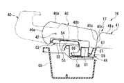
そして、上記配置とすることで、クッショントレー48は、前側分割体40の収納時の裏面40bに対向することになる。また、前側分割体40の裏面40b側に設けられたカップホルダ部61を有する上面部58が、図8に示すように、前側分割体40の収納時にクッショントレー48内に入り込んでその底面部66に当接しこのクッショントレー48で支持される。   And by setting it as the said arrangement | positioning, the cushion tray 48 will oppose the back surface 40b at the time of accommodation of the front side division body 40. FIG. Further, as shown in FIG. 8, the upper surface portion 58 having the cup holder portion 61 provided on the rear surface 40b side of the front divided body 40 enters the cushion tray 48 when the front divided body 40 is stored, and the bottom surface portion 66 thereof. And is supported by the cushion tray 48.

前側分割体40およびクッショントレー48の下側であって両側部フレーム35の間には、前方に引き出し可能な収納ボックス69が設けられている。この収納ボックス69は上部が開口した箱状のもので物品の収納が可能となっている。   A storage box 69 that can be pulled forward is provided between the side frames 35 below the front divided body 40 and the cushion tray 48. The storage box 69 is a box-shaped box having an open top and can store articles.

そして、本実施形態においては、図5および図6に示すように、回動状態にある上下反転後の前側分割体40には、上向きにテーブル部53およびカップホルダ部61が設けられることになり、テーブル部53に物品がカップホルダ部61に飲料容器が安定的に載置されることになる。   And in this embodiment, as shown in FIG.5 and FIG.6, the table part 53 and the cup holder part 61 will be provided upwards in the front side division body 40 after the upside down in the rotation state. Then, the article is stably placed on the table portion 53 and the beverage container is placed on the cup holder portion 61.

また、前側分割体40が回動状態にあるとき、収納状態では前側分割体40で覆われていたクッショントレー48が前側分割体40の前方移動で上向きに露出することになり、このクッショントレー48にも物品が安定的に載置されることになる。ここで、クッショントレー48の上側には、クッショントレー48の周縁部と水平方向における位置をほぼ合わせるようにして、前側分割体40の回動時の後側の面40eと後側分割体41の前面41cと一対の側部シート11のシートクッション12の中央シート16側の側面12cとが水平方向における四方を囲むことになるため、比較的高さの高い物品をクッショントレー48に載置させた場合であっても、前側分割体40の面40e、後側分割体41の前面41cおよび一対の側部シート11の側面12cのいずれかで支持することで安定的に載置させることができる。   When the front divided body 40 is in the rotating state, the cushion tray 48 covered with the front divided body 40 in the retracted state is exposed upward by the forward movement of the front divided body 40. In addition, the article is stably placed. Here, on the upper side of the cushion tray 48, the rear surface 40e and the rear divided body 41 of the front divided body 40 are rotated so that the peripheral edge of the cushion tray 48 is substantially aligned with the horizontal position. Since the front surface 41c and the side surface 12c on the central seat 16 side of the seat cushion 12 of the pair of side seats 11 surround the four sides in the horizontal direction, an article having a relatively high height was placed on the cushion tray 48. Even if it is a case, it can be made to mount stably by supporting in any one of the surface 40e of the front side division body 40, the front surface 41c of the rear side division body 41, and the side surface 12c of a pair of side part sheet | seat 11. FIG.

他方、前側分割体40は、収納状態にあるとき、図4に示すように、後側分割体41に隙間なく接触するとともに、後側分割体41の座面41aと自らの座面40aとをほぼ連続させる状態となって乗員の着席を可能とするが、このとき、図8に示すように前側分割体40の上面形成部59がクッショントレー48内に入り込んでその上面部58をクッショントレー48の底面部66に当接させることになる。これにより、前側分割体40が着席した乗員から受ける主に下方への荷重に対して、クッションフレーム43に固定されたテーブル部材52を側部フレーム35に固定されたクッショントレー48に当接させることから、これを良好に受けることができる。また、このように上面部58をクッショントレー48に入り込ませることで、上面部58と前側分割体40を支持する支持軸42との高さの差を大きくできる。   On the other hand, as shown in FIG. 4, when the front divided body 40 is in the retracted state, the front divided body 40 is in contact with the rear divided body 41 without a gap, and the seat surface 41a of the rear divided body 41 and its own seat surface 40a are connected. In this state, the occupant can take a seat, but at this time, as shown in FIG. 8, the upper surface forming portion 59 of the front divided body 40 enters the cushion tray 48 and the upper surface portion 58 is inserted into the cushion tray 48. It will be made to contact | abut to the bottom face part 66 of this. Accordingly, the table member 52 fixed to the cushion frame 43 is brought into contact with the cushion tray 48 fixed to the side frame 35 with respect to a downward load received from the occupant seated in the front side divided body 40. Therefore, this can be received well. Further, by allowing the upper surface portion 58 to enter the cushion tray 48 in this manner, the difference in height between the upper surface portion 58 and the support shaft 42 that supports the front divided body 40 can be increased.

以上に述べた本実施形態の車両用シート装置によれば、中央シート16においてシートクッション17の前側部分の前側分割体40をその前端側を中心に反転させると裏面40bに設けられたテーブル部53が上向きに配置されることになり、また、前側分割体40の収納時の裏面40bに対向して設けられたクッショントレー48が上向きに露出する。これにより、これらテーブル部53およびクッショントレー48に安定的に物品を載置させることができることから、乗員が乗車しない中央シート16に対し物品を安定的に載置させることが容易に可能となる。また、前側分割体40の裏面40b側のカップホルダ部61を有する上面部58が前側分割体40の収納時にクッショントレー48の底面部66に当接する位置つまり反転状態で高さが高くなる位置に配置されていることから、カップホルダ部61の深さを深くでき、その結果、飲料容器を安定的に載置させることができる。さらに、前側分割体40の収納時にカップホルダ部61が形成された上面部58がクッショントレー48に当接するため、前側分割体40を下側から確実に支えることができ、その結果、乗員の着席時の座り心地を損なうことがない。   According to the vehicle seat device of the present embodiment described above, when the front divided body 40 of the front portion of the seat cushion 17 in the center seat 16 is reversed about the front end side, the table portion 53 provided on the back surface 40b. Is disposed upward, and the cushion tray 48 provided facing the back surface 40b when the front divided body 40 is stored is exposed upward. As a result, since the articles can be stably placed on the table portion 53 and the cushion tray 48, the articles can be easily placed on the central seat 16 on which the occupant does not get on. Further, the upper surface 58 having the cup holder 61 on the back surface 40b side of the front divided body 40 is in contact with the bottom surface 66 of the cushion tray 48 when the front divided body 40 is stored, that is, in a position where the height is increased in the inverted state. Since it is arrange | positioned, the depth of the cup holder part 61 can be deepened, As a result, a drink container can be mounted stably. Further, since the upper surface portion 58 on which the cup holder portion 61 is formed contacts the cushion tray 48 when the front divided body 40 is stored, the front divided body 40 can be reliably supported from the lower side. It does not impair the comfort of time.

また、カップホルダ部61が円筒状をなしていることから、収納時にカップホルダ部61が形成された上面部58においてクッショントレー48に当接する前側分割体40の下部の剛性を高めることができ、その結果、座り心地をさらに良好にすることができる。   Further, since the cup holder portion 61 has a cylindrical shape, it is possible to increase the rigidity of the lower portion of the front divided body 40 that contacts the cushion tray 48 at the upper surface portion 58 where the cup holder portion 61 is formed during storage. As a result, the sitting comfort can be further improved.

加えて、クッショントレー48の下方に引き出し式の収納ボックス69が設けられているため、物品の収納を良好に行うことができる。しかも引き出し式であることから収納物を露出させずに収納できる。   In addition, since the drawer-type storage box 69 is provided below the cushion tray 48, the articles can be stored well. Moreover, since it is a drawer type, it can be stored without exposing the stored items.

本発明の一実施形態の車両用シート装置を含む車室内の平面図である。1 is a plan view of a passenger compartment including a vehicle seat device according to an embodiment of the present invention. 本発明の一実施形態の車両用シート装置を含む車室内の一状態の斜視図である1 is a perspective view of a state of a vehicle compartment including a vehicle seat device according to an embodiment of the present invention. 本発明の一実施形態の車両用シート装置を含む車室内の別の状態の斜視図であるIt is a perspective view of another state of the vehicle interior including the vehicle seat device of one embodiment of the present invention. 本発明の一実施形態の車両用シート装置を示す斜め前方から見た斜視図である。It is the perspective view seen from the slanting front which shows the seat device for vehicles of one embodiment of the present invention. 本発明の一実施形態の車両用シート装置を示す斜め後方から見た斜視図である。It is the perspective view seen from the slanting back which shows the vehicle seat apparatus of one Embodiment of this invention. 本発明の一実施形態の車両用シート装置を示す側方かつ斜め上側から見た斜視図である。It is the perspective view seen from the side and diagonally upper side which shows the vehicle seat apparatus of one Embodiment of this invention. 本発明の一実施形態の車両用シート装置における前側分割体を示す斜視図である。It is a perspective view which shows the front side division body in the vehicle seat apparatus of one Embodiment of this invention. 本発明の一実施形態の車両用シート装置の要部を示す側断面図である。It is a sectional side view showing the important section of the vehicular seat device of one embodiment of the present invention.

符号の説明Explanation of symbols

16 中央シート
17 シートクッション
40b 裏面
53 テーブル部
40 前側分割体
48 クッショントレー
61 カップホルダ部
58 上面部
69 収納ボックス
16 Central seat 17 Seat cushion 40b Back side 53 Table part 40 Front side division body 48 Cushion tray 61 Cup holder part 58 Upper surface part 69 Storage box

Claims (3)

シートクッションの前側部分が前端側を中心に反転することで裏面に設けられたテーブル部を上向きに配置する前側分割体とされ、該前側分割体の収納時の前記裏面に対向してクッショントレーが設けられ、前記前側分割体の前記裏面側にカップホルダ部を有する上面部を形成するとともに、前記前側分割体の収納時に前記上面部を前記クッショントレーに当接させることを特徴とする車両用シート装置。   The front portion of the seat cushion is inverted about the front end side, so that the table portion provided on the back surface is a front divided body, and the cushion tray is opposed to the back surface when the front divided body is stored. The vehicle seat is provided, wherein an upper surface portion having a cup holder portion is formed on the back surface side of the front divided body, and the upper surface portion is brought into contact with the cushion tray when the front divided body is stored. apparatus. 前記カップホルダ部が筒状をなしていることを特徴とする請求項1記載の車両用シート装置。   The vehicle seat device according to claim 1, wherein the cup holder portion has a cylindrical shape. 前記クッショントレーの下方に引き出し式の収納ボックスが設けられていることを特徴とする請求項1または2記載の車両用シート装置。
The vehicle seat device according to claim 1, wherein a drawer-type storage box is provided below the cushion tray.
JP2004113235A 2004-04-07 2004-04-07 Vehicle seat device Expired - Fee Related JP4060285B2 (en)

Priority Applications (1)

Application Number Priority Date Filing Date Title
JP2004113235A JP4060285B2 (en) 2004-04-07 2004-04-07 Vehicle seat device

Applications Claiming Priority (1)

Application Number Priority Date Filing Date Title
JP2004113235A JP4060285B2 (en) 2004-04-07 2004-04-07 Vehicle seat device

Publications (2)

Publication Number Publication Date
JP2005297633A true JP2005297633A (en) 2005-10-27
JP4060285B2 JP4060285B2 (en) 2008-03-12

Family

ID=35329726

Family Applications (1)

Application Number Title Priority Date Filing Date
JP2004113235A Expired - Fee Related JP4060285B2 (en) 2004-04-07 2004-04-07 Vehicle seat device

Country Status (1)

Country Link
JP (1) JP4060285B2 (en)

Cited By (1)

* Cited by examiner, † Cited by third party
Publication number Priority date Publication date Assignee Title
JP2006240553A (en) * 2005-03-04 2006-09-14 Kanto Auto Works Ltd Car seat structure

Citations (5)

* Cited by examiner, † Cited by third party
Publication number Priority date Publication date Assignee Title
JPS59179128U (en) * 1983-05-18 1984-11-30 池田物産株式会社 table storage sheet
JPH08127279A (en) * 1994-11-01 1996-05-21 Hino Motors Ltd Seat for automobile
JPH1053059A (en) * 1996-08-09 1998-02-24 Inoac Corp Vessel holder
JPH10278643A (en) * 1997-04-10 1998-10-20 Takashimaya Nippatsu Kogyo Kk Seat for vehicle
JP2002282090A (en) * 2001-03-27 2002-10-02 Johnson Controls Automotive Systems Corp Vehicle seat with glove compartment

Patent Citations (5)

* Cited by examiner, † Cited by third party
Publication number Priority date Publication date Assignee Title
JPS59179128U (en) * 1983-05-18 1984-11-30 池田物産株式会社 table storage sheet
JPH08127279A (en) * 1994-11-01 1996-05-21 Hino Motors Ltd Seat for automobile
JPH1053059A (en) * 1996-08-09 1998-02-24 Inoac Corp Vessel holder
JPH10278643A (en) * 1997-04-10 1998-10-20 Takashimaya Nippatsu Kogyo Kk Seat for vehicle
JP2002282090A (en) * 2001-03-27 2002-10-02 Johnson Controls Automotive Systems Corp Vehicle seat with glove compartment

Cited By (1)

* Cited by examiner, † Cited by third party
Publication number Priority date Publication date Assignee Title
JP2006240553A (en) * 2005-03-04 2006-09-14 Kanto Auto Works Ltd Car seat structure

Also Published As

Publication number Publication date
JP4060285B2 (en) 2008-03-12

Similar Documents

Publication Publication Date Title
US6869121B2 (en) Seat structure for vehicle
JP5600150B2 (en) Aircraft passenger seat
JP2004249782A (en) Seat device of vehicle
US20020047287A1 (en) Vehicular seat system
JP6554371B2 (en) Vehicle seat
JP2009214798A (en) Vehicle seat
JP4060285B2 (en) Vehicle seat device
JP5272574B2 (en) Center console structure of the vehicle
JP2021079894A (en) Arm rest of vehicle seat
JP2015042522A (en) Cup holder
JP2004243876A (en) Vehicle seat storage structure
JP2012162120A (en) Vehicle seat
JP2006290353A (en) Luggage compartment structure in rear part of automobile
JP6016194B2 (en) Vehicle seat
JP4050247B2 (en) Vehicle seat structure
JP2002114069A (en) Seat device for automobile
JP6616373B2 (en) Vehicle seat device
JP2020128176A (en) Seat side table
JP2007290458A (en) Vehicular console box
JP2026002526A (en) Armrest and vehicle seat
JP2007015431A (en) Structure of slide type console box of vehicle
JP2008074122A (en) Small article storage structure for vehicle seat
JP2015140132A (en) Body structure with vehicle seat
JP2005297632A (en) Vehicle seat structure
JP7240620B2 (en) Storage box

Legal Events

Date Code Title Description
A977 Report on retrieval

Free format text: JAPANESE INTERMEDIATE CODE: A971007

Effective date: 20070425

A131 Notification of reasons for refusal

Free format text: JAPANESE INTERMEDIATE CODE: A131

Effective date: 20070522

A521 Written amendment

Free format text: JAPANESE INTERMEDIATE CODE: A523

Effective date: 20070720

A02 Decision of refusal

Free format text: JAPANESE INTERMEDIATE CODE: A02

Effective date: 20070821

A521 Written amendment

Free format text: JAPANESE INTERMEDIATE CODE: A523

Effective date: 20071004

A911 Transfer of reconsideration by examiner before appeal (zenchi)

Free format text: JAPANESE INTERMEDIATE CODE: A911

Effective date: 20071026

TRDD Decision of grant or rejection written
A01 Written decision to grant a patent or to grant a registration (utility model)

Free format text: JAPANESE INTERMEDIATE CODE: A01

Effective date: 20071211

A61 First payment of annual fees (during grant procedure)

Free format text: JAPANESE INTERMEDIATE CODE: A61

Effective date: 20071219

FPAY Renewal fee payment (event date is renewal date of database)

Free format text: PAYMENT UNTIL: 20101228

Year of fee payment: 3

R150 Certificate of patent or registration of utility model

Free format text: JAPANESE INTERMEDIATE CODE: R150

FPAY Renewal fee payment (event date is renewal date of database)

Free format text: PAYMENT UNTIL: 20101228

Year of fee payment: 3

FPAY Renewal fee payment (event date is renewal date of database)

Free format text: PAYMENT UNTIL: 20111228

Year of fee payment: 4

LAPS Cancellation because of no payment of annual fees