JP2005297612A - Vehicle driving force control device and driving force control method - Google Patents
Vehicle driving force control device and driving force control method Download PDFInfo
- Publication number
- JP2005297612A JP2005297612A JP2004112386A JP2004112386A JP2005297612A JP 2005297612 A JP2005297612 A JP 2005297612A JP 2004112386 A JP2004112386 A JP 2004112386A JP 2004112386 A JP2004112386 A JP 2004112386A JP 2005297612 A JP2005297612 A JP 2005297612A
- Authority
- JP
- Japan
- Prior art keywords
- vehicle
- deceleration
- preceding vehicle
- driving force
- force control
- Prior art date
- Legal status (The legal status is an assumption and is not a legal conclusion. Google has not performed a legal analysis and makes no representation as to the accuracy of the status listed.)
- Pending
Links
Images

Landscapes
- Control Of Driving Devices And Active Controlling Of Vehicle (AREA)
- Controls For Constant Speed Travelling (AREA)
- Regulating Braking Force (AREA)
- Control Of Vehicle Engines Or Engines For Specific Uses (AREA)
- Control Of Transmission Device (AREA)
- Traffic Control Systems (AREA)
Abstract
【課題】運転者の減速意志により自車を先行車両に対して追従走行させる際の運転者の違和感や不快感を低減することができる車両の駆動力制御装置を提供すること。
【解決手段】減速検出手段であるアクセルセンサ10により運転者の減速意志を検出した際に、自車100と自車の前方を走行する先行車両200との位置関係に応じて自車の減速度を制御する車両の駆動力制御装置において、自車100が先行車両200に対して追従走行を行っているかを判断する追従走行判断手段である追従走行判断部44と、先行車両200から送信されるこの先行車両200の減速度データを受信する減速度データ受信手段である減速度データ受信部46とを備え、追従走行判断部44により自車100が先行車両200に対して追従走行を行っていると判断した際に、減速度データ受信部46により受信した先行車両200の減速度データに基づいて自車100の減速度を制御する。
【選択図】 図1To provide a driving force control device for a vehicle capable of reducing a driver's uncomfortable feeling and discomfort when the host vehicle follows the preceding vehicle according to the driver's willingness to decelerate.
When a driver's intention to decelerate is detected by an accelerator sensor (deceleration detecting means), the deceleration of the own vehicle is determined according to the positional relationship between the own vehicle and a preceding vehicle traveling in front of the own vehicle. In the vehicle driving force control apparatus that controls the vehicle, the following traveling determination unit 44 that is a following traveling determining unit that determines whether the host vehicle 100 is following following the preceding vehicle 200, and is transmitted from the preceding vehicle 200. A deceleration data receiving unit 46 which is a deceleration data receiving means for receiving the deceleration data of the preceding vehicle 200, and the own vehicle 100 is following the preceding vehicle 200 by the following traveling determination unit 44. Is determined, the deceleration of the host vehicle 100 is controlled based on the deceleration data of the preceding vehicle 200 received by the deceleration data receiver 46.
[Selection] Figure 1
Description
この発明は、車両の駆動力制御装置および駆動力制御方法に関し、更に詳しくは、運転者の減速意志を検出した際に、自車の減速度を制御する車両の駆動力制御装置および駆動力制御方法に関する。 The present invention relates to a vehicle driving force control device and a driving force control method, and more particularly, to a vehicle driving force control device and a driving force control that control deceleration of the host vehicle when a driver's intention to decelerate is detected. Regarding the method.
従来、自車とこの自車の前方を走行する先行車両との位置関係に応じて、自車を先行車両に対して追従走行させるための車両の駆動力制御装置が提案されている。自車を先行車両に対して追従走行させるための車両の駆動力制御装置は、運転者の減速意志を必要とせずに、自車と先行車両との位置関係に応じて自車の加減速度を制御するものであり、例えば特許文献1に示すものがある。特許文献1に示す従来の車両の駆動力制御装置は、自車を先行車両に対して追従走行させる追従走行装置であり、カルマンフィルタを用いて先行車両(先行車)の加減速度を推定することで推定加減速度を導出し、この推定加減速度から自車と先行車両との推定車間距離を導出し、この推定車間距離と実際の車間距離との差から推定誤差を導出する。そして、この推定誤差に基づいて、自車が先行車両の加減速度の変化等に伴う推定遅れ状態であると判断すると、先行車両の推定加速度を加味した自車の目標加減速度を算出し、自車が先行車両の加減速度の変化等に伴う推定遅れ状態でないと判断すると、先行車両の推定加減度を加味しないで自車の目標加減速度を算出するものである。この従来の車両の駆動力制御装置では、先行車両の減速に対して、応答性よく、かつ高精度に追従して所定の車間距離を保持するように自車を減速することができるものである。
2. Description of the Related Art Conventionally, there has been proposed a vehicle driving force control device for causing a subject vehicle to follow the preceding vehicle in accordance with the positional relationship between the subject vehicle and a preceding vehicle traveling in front of the subject vehicle. The vehicle driving force control device for causing the vehicle to follow the preceding vehicle does not require the driver's intention to decelerate, and the acceleration / deceleration of the own vehicle is determined according to the positional relationship between the own vehicle and the preceding vehicle. For example, there is one shown in
上記特許文献1に示すような従来の車両の駆動力制御装置は、自車の先行車両に対する追従走行の困難さのために提案されている技術である。これは、自車を先行車両に対して所定の車間距離で走行させる、つまり追従走行させる場合には、先行車両の加減速度に自車の加減速度を一致させる必要があるためである。特に、自車と先行車両が下り坂の道路、つまり降坂路を走行している際に、自車を先行車両に対して追従走行させることは、先行車両の減速度と自車の減速度が異なるため、特に困難である。通常、車両が降坂路を走行する際には、運転者は自車の車速の上昇を抑えるために、自車の減速度を調整する。具体的には、運転者は、基本的にアクセルペダルから足を離すことで発生するエンジンブレーキや、ブレーキペダルを踏み込むことで発生する制動装置による制動力を用いて自車の減速度を調整する。
The conventional driving force control device for a vehicle as shown in
従って、長降坂路を走行する先行車両の運転者がアクセルペダルから足を離すことで発生するエンジンブレーキにより先行車両の減速度を得ている場合に、先行車両に対して追従走行する自車の運転者も先行車両の運転者と同様にアクセルペダルから足を離すことで発生するエンジンブレーキにより自車の減速度を得ていても、先行車両におけるエンジンブレーキによる減速度と自車におけるエンジンブレーキによる減速度が異なるため、自車を先行車両に対して追従走行させることは困難である。これは、車両は、その車種や排気量、重量、変速比などによってその減速度が変化するためである。 Therefore, when the driver of the preceding vehicle traveling on the long downhill road has obtained the deceleration of the preceding vehicle by the engine brake generated by releasing his / her foot from the accelerator pedal, Even if the driver obtains the deceleration of the vehicle by the engine brake generated by releasing the foot from the accelerator pedal in the same manner as the driver of the preceding vehicle, the deceleration by the engine brake in the preceding vehicle and the engine brake in the own vehicle Since the deceleration is different, it is difficult to make the host vehicle follow the preceding vehicle. This is because the deceleration of the vehicle changes depending on the vehicle type, displacement, weight, gear ratio, and the like.
例えば、自車が追従走行する対象である先行車両の減速度がこの自車の減速度よりも高い場合は、自車と先行車両との車間距離は、先行車両の減速度と自車の減速度との差により縮まることとなる。この場合、運転者は、自車を所定の車間距離で先行車両に対して追従走行させようとするため、自車の減速度を先行車両の減速度と一致するように高くする。例えば、運転者は、間断なくブレーキペダルを踏み込み、制動装置による制動力により自車の減速度を高くし、先行車両の減速度と一致させようとする。しかし、運転者は、自車の減速度が先行車両の減速度と一致し、自車を先行車両に対して追従走行させることができるようになると、ブレーキペダルから足を離してしまう。従って、自車の減速度が小さくなり、自車と先行車両との車間距離が縮まり始める。運転者は、車間距離がある程度縮まると、自車の減速度を先行車両の減速度と再度一致させるために、再度間断なくブレーキペダルを踏み込むこととなる。つまり、運転者は、運転者の減速意志により自車を先行車両に対して追従走行させるために、ブレーキペダルの操作を頻繁に繰り返す必要があった。 For example, if the deceleration of the preceding vehicle that the subject vehicle is following is higher than the deceleration of the subject vehicle, the distance between the subject vehicle and the preceding vehicle is the deceleration of the preceding vehicle and the deceleration of the subject vehicle. It will shrink due to the difference with the speed. In this case, since the driver tries to follow the preceding vehicle with the preceding vehicle at a predetermined inter-vehicle distance, the driver increases the deceleration of the own vehicle to coincide with the deceleration of the preceding vehicle. For example, the driver depresses the brake pedal without interruption, and increases the deceleration of the own vehicle by the braking force of the braking device so as to match the deceleration of the preceding vehicle. However, the driver lifts his / her foot from the brake pedal when the deceleration of the own vehicle coincides with the deceleration of the preceding vehicle and the vehicle can follow the preceding vehicle. Accordingly, the deceleration of the own vehicle is reduced, and the inter-vehicle distance between the own vehicle and the preceding vehicle starts to decrease. When the inter-vehicle distance is reduced to some extent, the driver depresses the brake pedal again without interruption in order to make the deceleration of the own vehicle coincide with the deceleration of the preceding vehicle again. That is, the driver has to frequently repeat the operation of the brake pedal in order to cause the vehicle to follow the preceding vehicle according to the driver's willingness to decelerate.
あるいは、運転者は、シフトレバーを操作することで、自車の内燃機関であるエンジンに連結された変速機(自動変速機、手動変速機)をダウンシフトさせ、自動変速機の変速比を変更することでエンジンブレーキによる減速度を高くし、先行車両の減速度と一致させようとする。しかし、特に、複数の変速段を有し、変速段ごとに変速比が異なる有段変速機(一部の無段変速機も含む)においては、上記のように運転者がシフトレバーを操作することで、この有段変速機をダウンシフトさせた結果、変更された変速比により発生するエンジンブレーキによる減速度が先行車両の減速度よりも高くなる虞がある。従って、自車と先行車両との車間距離が離れ始める。運転者は、車間距離がある程度離れると、自車を先行車両に対して追従走行させるために、離していたアクセルペダルを踏み込み、自車を加速させる、または有段変速機をアップシフトさせて、自車の減速度を先行車両の減速度よりも小さくすることとなる。つまり、運転者は、運転者の減速意志により自車を先行車両に対して追従走行させるために、アクセルペダルの操作あるいはシフトレバーの操作を頻繁に繰り返す必要があった。 Alternatively, the driver operates the shift lever to downshift the transmission (automatic transmission, manual transmission) connected to the engine that is the internal combustion engine of the own vehicle, thereby changing the gear ratio of the automatic transmission. By doing so, the deceleration by the engine brake is increased, and it tries to coincide with the deceleration of the preceding vehicle. However, in particular, in a stepped transmission (including some continuously variable transmissions) having a plurality of shift stages and different gear ratios for each shift stage, the driver operates the shift lever as described above. As a result, as a result of downshifting the stepped transmission, the deceleration due to the engine brake generated by the changed gear ratio may be higher than the deceleration of the preceding vehicle. Accordingly, the inter-vehicle distance between the own vehicle and the preceding vehicle starts to increase. When the distance between the vehicles is some distance away, the driver depresses the accelerator pedal that has been released to make the vehicle follow the preceding vehicle, accelerate the vehicle, or upshift the stepped transmission, The deceleration of the own vehicle is made smaller than the deceleration of the preceding vehicle. That is, the driver has to frequently repeat the operation of the accelerator pedal or the operation of the shift lever in order to make the vehicle follow the preceding vehicle by the driver's willingness to decelerate.
本発明は、上記に鑑みてなされたものであって、運転者の減速意志により自車を先行車両に対して追従走行させる際の運転者の違和感や不快感を低減することができる車両の駆動力制御装置および駆動力制御方法を提供することを目的とする。 The present invention has been made in view of the above, and is a vehicle drive that can reduce the driver's uncomfortable feeling and discomfort when the vehicle follows the preceding vehicle due to the driver's willingness to decelerate. An object is to provide a force control device and a driving force control method.
上述した課題を解決し、目的を達成するために、この発明では、減速検出手段により運転者の減速意志を検出した際に、自車の前方を走行する先行車両の情報に基づいて車両の減速度を制御する車両の駆動力制御装置において、自車が先行車両に対して追従走行を行っているかを判断する追従走行判断手段と、先行車両から送信される当該先行車両の減速度データを受信する減速度データ受信手段とを備え、追従走行判断手段により自車が先行車両に対して追従走行を行っていると判断した際に、減速度データ受信手段により受信した先行車両の減速度データに基づいて自車の減速度を制御することを特徴とする。 In order to solve the above-described problems and achieve the object, according to the present invention, when the driver's intention to decelerate is detected by the deceleration detecting means, the number of vehicles is reduced based on the information on the preceding vehicle traveling ahead of the own vehicle. In a driving force control device for a vehicle that controls speed, it receives following travel determination means for determining whether the host vehicle is following the preceding vehicle, and receives deceleration data of the preceding vehicle transmitted from the preceding vehicle. Deceleration data receiving means for detecting the preceding vehicle deceleration data received by the deceleration data receiving means when the following traveling judgment means determines that the host vehicle is following the preceding vehicle. Based on this, the deceleration of the own vehicle is controlled.
また、この発明では、自車の前方を走行する先行車両の情報に基づいて車両の減速度を制御する車両の駆動力制御方法において、運転者の減速意志を判断する手順と、自車が先行車両に対して追従走行を行っているかを判断する手順と、先行車両から送信される当該先行車両の減速度データを受信する手順と、自車の走行する道路の混雑度を判断する手順と、自車が先行車両に対して追従走行を行っている際に、受信した先行車両の減速度データに基づいて自車の減速度を制御する手順とを含むことを特徴とする。 Further, according to the present invention, in a vehicle driving force control method for controlling deceleration of a vehicle based on information on a preceding vehicle traveling in front of the host vehicle, a procedure for determining the driver's intention to decelerate, A procedure for determining whether the vehicle is following the vehicle, a procedure for receiving deceleration data of the preceding vehicle transmitted from the preceding vehicle, a procedure for determining the degree of congestion on the road on which the vehicle is traveling, And a procedure for controlling the deceleration of the host vehicle based on the received deceleration data of the preceding vehicle when the host vehicle is following the preceding vehicle.
これらの発明によれば、自車は、減速度データ受信手段により先行車両の減速度データからこの先行車両の減速度を直接的あるいは間接的に受信し、この先行車両の減速度と一致あるいは近似するように自車の減速度を制御する。従って、運転者の減速意志により、自車が減速を開始しても、この自車の減速度と先行車両の減速度との差がない状態あるいは略ない状態であるため、自車と先行車両とは所定の車間距離を長時間維持することができる。これにより、自車を先行車両に対して追従走行させるために、ブレーキペダル、アクセルペダル、あるいはシフトレバーの操作を繰り返す頻度を減少させることができる。 According to these inventions, the own vehicle receives the deceleration of the preceding vehicle directly or indirectly from the deceleration data of the preceding vehicle by the deceleration data receiving means, and matches or approximates the deceleration of the preceding vehicle. To control the deceleration of the vehicle. Therefore, even if the own vehicle starts to decelerate due to the driver's will to decelerate, there is no or almost no difference between the deceleration of the own vehicle and the deceleration of the preceding vehicle. Can maintain a predetermined inter-vehicle distance for a long time. Accordingly, the frequency of repeating the operation of the brake pedal, the accelerator pedal, or the shift lever in order to cause the host vehicle to follow the preceding vehicle can be reduced.
また、この発明では、上記車両の駆動力制御装置において、自車に搭載された変速機の変速比を変更する変速比変更手段をさらに備え、変速比変更手段は、減速度データ受信手段により受信した減速度データに基づいて、自車の変速機の変速比を自車の減速度が先行車両の減速度と一致あるいは近似する減速度となる変速比に変更することを特徴とする。 According to the present invention, the vehicle driving force control apparatus further includes gear ratio changing means for changing a gear ratio of a transmission mounted on the host vehicle, and the gear ratio changing means is received by the deceleration data receiving means. Based on the deceleration data thus obtained, the speed ratio of the transmission of the host vehicle is changed to a speed ratio at which the deceleration of the host vehicle becomes a deceleration that matches or approximates the deceleration of the preceding vehicle.
この発明によれば、変速機の変速比を変速比変更手段より変更することで、減速度データ受信手段により受信した先行車両の減速度データに基づいて自車の減速度を制御する。変速比変更手段により変更できる変速機の変速比における自車の減速度のうち先行車両の減速度に一致あるいは近似する減速度となる変速比に自車の変速機を変速比変更手段により変更する。これにより、運転者の減速意志により、自車が減速を開始しても、この自車の減速度と先行車両の減速度との差がない状態あるいは略ない状態であるため、自車を先行車両に対して追従走行させるために、ブレーキペダル、アクセルペダル、あるいはシフトレバーの操作を繰り返す頻度を減少させることができる。 According to the present invention, the deceleration of the own vehicle is controlled based on the deceleration data of the preceding vehicle received by the deceleration data receiving means by changing the speed ratio of the transmission from the speed ratio changing means. The transmission ratio of the own vehicle is changed by the transmission ratio changing means to a speed ratio that is a deceleration that matches or approximates the deceleration of the preceding vehicle among the decelerations of the own vehicle in the transmission ratio of the transmission that can be changed by the transmission ratio changing means. . As a result, even if the host vehicle starts to decelerate due to the driver's will to decelerate, there is no difference between the deceleration of the host vehicle and the deceleration of the preceding vehicle. In order to follow the vehicle, the frequency of repeating the operation of the brake pedal, the accelerator pedal, or the shift lever can be reduced.
また、この発明では、上記車両の駆動力制御装置において、自車に搭載された回生ブレーキ装置の回生量を変更する回生量変更手段をさらに備え、回生量変更手段は、減速度データ受信手段により受信した減速度データに基づいて、自車の回生ブレーキ装置の回生量を自車の減速度が先行車両の減速度と一致あるいは近似する減速度となる回生量に変更することを特徴とする。 In the present invention, the driving force control device for a vehicle further includes a regeneration amount changing means for changing a regeneration amount of a regenerative brake device mounted on the host vehicle, and the regeneration amount changing means is provided by the deceleration data receiving means. Based on the received deceleration data, the regeneration amount of the regenerative braking device of the own vehicle is changed to a regeneration amount at which the deceleration of the own vehicle coincides with or approximates the deceleration of the preceding vehicle.
この発明によれば、自車に減速度を与える回生ブレーキ装置の回生量を回生量変更手段より変更することで、減速度データ受信手段により受信した先行車両の減速度データに基づいて自車の減速度を制御する。回生量変更手段により変更できる回生ブレーキ装置の回生量における自車の減速度のうち先行車両の減速度に一致あるいは近似する減速度となる回生量に自車の回生ブレーキ装置を回生量変更手段により変更する。これにより、運転者の減速意志により、自車が減速を開始しても、この自車の減速度と先行車両の減速度との差がない状態あるいは略ない状態であるため、自車を先行車両に対して追従走行させるために、ブレーキペダル、アクセルペダル、あるいはシフトレバーの操作を繰り返す頻度を減少させることができる。 According to the present invention, the regeneration amount of the regenerative braking device that gives a deceleration to the host vehicle is changed by the regeneration amount changing unit, so that the vehicle's own vehicle is based on the deceleration data of the preceding vehicle received by the deceleration data receiving unit. Control the deceleration. The regenerative braking device of the own vehicle is regenerated by the regenerative amount changing means to a regenerative amount that matches or approximates the deceleration of the preceding vehicle in the regenerative amount of the regenerative braking device that can be changed by the regenerative amount changing means. change. As a result, even if the host vehicle starts to decelerate due to the driver's will to decelerate, there is no difference between the deceleration of the host vehicle and the deceleration of the preceding vehicle. In order to follow the vehicle, the frequency of repeating the operation of the brake pedal, the accelerator pedal, or the shift lever can be reduced.
この発明にかかる車両の駆動力制御装置および駆動力制御方法は、先行車両の減速度データに基づいて自車の減速度を制御し、この自車の減速度と先行車両の減速度との差がない状態あるいは略ない状態とするので、自車を先行車両に対して追従走行させるために、ブレーキペダル、アクセルペダル、あるいはシフトレバーの操作を繰り返す頻度を減少させることができ、運転者の減速意志により自車を先行車両に対して追従走行させる際の運転者の違和感や不快感を低減することができる。 The driving force control apparatus and driving force control method for a vehicle according to the present invention controls the deceleration of the own vehicle based on the deceleration data of the preceding vehicle, and the difference between the deceleration of the own vehicle and the deceleration of the preceding vehicle. In order to make the vehicle follow the preceding vehicle, the frequency of repeating the operation of the brake pedal, accelerator pedal, or shift lever can be reduced, and the driver's deceleration It is possible to reduce the driver's uncomfortable feeling and uncomfortable feeling when the vehicle follows the preceding vehicle by will.
以下、この発明につき図面を参照しつつ詳細に説明する。なお、下記の実施例によりこの発明が限定されるものではない。また、下記の実施例における構成要素には、当業者が容易に想定できるもの或いは実質的に同一のものが含まれる。 Hereinafter, the present invention will be described in detail with reference to the drawings. In addition, this invention is not limited by the following Example. In addition, constituent elements in the following embodiments include those that can be easily assumed by those skilled in the art or those that are substantially the same.
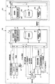
図1は、この発明にかかる車両の駆動力制御装置の構成例を示す図である。図2は、車両の構成例を示す図である。図1に示すように、自車100に搭載されるこの発明にかかる車両の駆動力制御装置1は、自動変速機2と、自車100とこの自車100の前方を走行する先行車両200との位置関係を検出する先行車両検出装置3と、処理部42に追従走行判断手段である追従走行判断部44と、変速比変更手段である変速比変更部45とを有するとともに、先行車両から送信される減速度データを受信する減速度データ受信手段である減速度データ受信部46を有するECU(Engine Control Unit)4とにより構成されている。なお、5は、内燃機関であるエンジンである。6は、エンジン5の図示しないクランクシャフトで発生する駆動力を自動変速機2に伝達するトルクコンバータである。また、7は、自動変速機2の変速比を切り替える油圧供給装置である。また、8は、エンジン5に吸気する空気を車両外部から導入する吸気系統である。また、9は、エンジンから排気される排気ガスを車両外部に排気する排気系統である。
FIG. 1 is a diagram showing a configuration example of a vehicle driving force control apparatus according to the present invention. FIG. 2 is a diagram illustrating a configuration example of a vehicle. As shown in FIG. 1, a vehicle driving
自動変速機2は、無段変速機であり、エンジン5にトルクコンバータ6を介して連結されている。エンジン5の図示しないクランクシャフトで発生する駆動力は、トルクコンバータ6を介して自動変速機2に伝達される。そして、図2に示すように、この自動変速機2からデファレンシャルギヤ13を介して図示しないドライブシャフトに伝達され、駆動輪14に伝達される。また、自動変速機2は、図示しないベルトが巻き掛けられたプライマリープーリーおよびセカンダリープーリーの溝幅を変更することで変速比を無段階に制御可能であり、自車の運転状況により後述するECU4から出力される変速信号に基づいて油圧供給装置7を介して変速比が無段階に制御されるものである。ここで、油圧供給装置7は、上記ECU4から出力された変速信号に基づいて自動変速機2の図示しないプライマリープーリーとセカンダリープーリーの溝幅を変更するための油圧を供給するものである。
The automatic transmission 2 is a continuously variable transmission and is connected to the
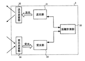
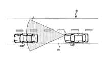
図3−1は、先行車両検出装置の構成例を示す図である。図3−2は、自車と前方車両との関係を示す図である。先行車両検出装置3は、レーザレーダ装置であり、自車100の前部に取り付けられている。先行車両検出装置3は、送光部31と、送光走査部32と、受光部33と、受光走査部34と、距離計測部35とにより構成されている。送光部31には、レーザを出力するレーザダイオードとこのレーザダイオードを駆動する駆動回路とにより構成されている。送光走査部32は、送光部31のレーザダイオードが出力したレーザを反射させる反射ミラーとこの反射ミラーを上下に揺動させるモータなどから構成される反射ミラー駆動部とにより構成されている。受光部33は、受光レンズとこの受光レンズで収束した反射波を電気信号に変換するフォトダイオードなどにより構成されている。受光走査部34は、図3−2に示すように、上記送光走査部32を介して送光部31から自車100の前方に出力されたレーザが自車100の前方に位置する前方車両200に反射した反射波を反射させて上記受光レンズに導く受光ミラーとこの受光ミラーを左右に揺動させるモータなどから構成される受光ミラー駆動部とにより構成されている。距離計測部35は、上記送光部31の駆動回路、送光走査部32の反射ミラー駆動部、受光走査部34の受光ミラー駆動部を制御し、かつレーザの送光から反射波が受光されるまでの時間から自車100と前方車両との位置関係である車間距離を算出するものである。
FIG. 3A is a diagram illustrating a configuration example of a preceding vehicle detection device. FIG. 3-2 is a diagram illustrating a relationship between the host vehicle and the preceding vehicle. The preceding vehicle detection device 3 is a laser radar device and is attached to the front portion of the
具体的には、送光部31から出力されたレーザLは、送光走査部32を介して、自車100の前方に出力される。この出力されたレーザLの有効領域(反射波が受光走査部34を介して受光部33が検出される領域)内に道路Rの同一車線R1において自車の前方を走行する先行車両200が位置すると、レーザLは先行車両200のリフレクターなどにより反射され反射波となり、自車100に戻ってくる。受光部33には、受光走査部34を介してこの自車100に戻ってきた反射波が入力される。距離計測部35は、送光部31によるレーザLの送光から受光部33による反射波の受光までの時間を計測し、この時間から自車100が走行している道路Rの同一車線R1の先方に車両(先行車両200)がいることを検出するするとともに、自車100と先行車両200との車間距離を算出する。なお、距離計測部35で算出された車間距離は、図1に示すように後述するECU4に出力される。
Specifically, the laser L output from the
ECU4は、自車100が上記先行車両検出装置3により検出された先行車両200に対して追従走行を行っているかを判断する追従走行判断手段である。また、後述する減速度データ受信部により取得した先行車両200の減速度データに基づいて自動変速機2の変速比を変更することで、自車の減速度を制御する変速比変更手段でもある。
The
また、ECU4は、エンジン5が搭載された車両の各所に取り付けられたセンサから、各種入力信号が入力される。具体的には、例えばエンジン5の図示しないクランクシャフトに取り付けられた角度センサにより検出されたエンジン回転数Ne100〔rpm〕、吸気系統8に取り付けられたエアフロメータ82により検出されたエアフィルタ81を介して吸気される吸入空気量、減速検出手段であるアクセルセンサ10により検出された運転者が操作するアクセルペダルの操作量(アクセル開度)、車速センサ11により検出された自車100の車速V100〔km/h〕、シフトセンサ12により検出された運転者が操作するシフトレバーのシフトポジション、上記先行車両検出装置3から出力された車間距離など、後述する減速度データ受信部46により受信した減速度データなどがある。これら入力信号および記憶部43に記憶されている噴射制御マップや変速マップなどの各種マップに基づいて、エンジン5の図示しないインジェクタの噴射タイミングや噴射量を制御する噴射信号、エンジン5の図示しない点火プラグの点火タイミングを制御する点火信号、吸気系統8のスロットルバルブ83のバルブ開度を制御するバルブ開度信号などのエンジン5の出力制御を行う信号および自動変速機2の変速比の変更する変速制御を行う変速信号などの出力信号を出力する。なお、ECU4は、自動変速機2の変速制御に伴って、エンジン回転数を適切に変化させるために、上記エンジン5の出力制御を行っても良い。
The
具体的には、上記入力信号や出力信号の入出力を行う入出力ポート(I/O)41と、追従走行判断部44、変速比変更部45を有する処理部42と、上記噴射制御マップや変速マップなどの各種マップなどを格納する記憶部43と、減速度データ受信部46とにより構成されている。処理部42は、メモリおよびCPU(Central Processing Unit)により構成され、車両の駆動力制御方法などに基づくプログラムをメモリにロードして実行することにより、車両の駆動力制御方法などを実現させるものであっても良い。また、記憶部43は、フラッシュメモリ等の不揮発性のメモリ、ROM(Read Only Memory)のような読み出しのみが可能な揮発性のメモリあるいはRAM(Random Access Memory)のような読み書きが可能な揮発性のメモリ、あるいはこれらの組み合わせにより構成することができる。また、減速度データ受信部46じゃ、後述する先行車両200のECU201の減速度データ送信部206から送信された処理部203の減速度算出部205により算出された先行車両200の減速度である減速度データを受信するものである。なお、この減速度データの送受信は、自車100と先行車両200とが直接的に行っても良いし、他の通信手段、例えば衛星などを介して間接的に行っても良い。また、この実施例では、車両の駆動力制御方法をECU4により実現させるが、これに限定されるものではなく、このECU4とは個別に形成された制御装置により実現しても良い。
Specifically, an input / output port (I / O) 41 for inputting and outputting the input signal and the output signal, a
自車100の前方を走行する先行車両200は、自車100と同様に構成されており、図2に示すように、自動変速機209がエンジン207にトルクコンバータ208を介して連結されている。エンジン207の図示しないクランクシャフトで発生する駆動力は、トルクコンバータ208を介して自動変速機209に伝達される。そして、この自動変速機209からデファレンシャルギヤ210を介して図示しないドライブシャフトに伝達され、駆動輪211に伝達される。また、先行車両200のECU201は、自車100とほぼ同様に構成されており、入出力ポート202と、先行車両200の減速度を算出する減速度算出部205を有する処理部203と、噴射制御マップや変速マップなどの各種マップなどを格納する記憶部204と、減速度データ送信部206とにより構成されている。処理部203の減速度算出部205は、先行車両200の減速度を算出し、この先行車両200の減速度は、減速度データとして入出力ポート202を介して減速度データ送信部206に入力され、この減速度データ送信部206により自車100のECU4の減速度データ受信部46に送信される。なお、自車100の減速度データ受信部46と先行車両200の減速度データ送信部206は、受信機能あるいは送信機能のみしか有していないが、ともに送受信機能を有していても良い。
A preceding
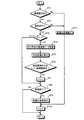
次に、この発明にかかる車両の駆動力制御装置1を用いた車両の駆動力制御方法について説明する。図4は、この発明にかかる車両の駆動力制御装置の動作フローである。まず、ECU4の処理部42は、減速検出手段であるアクセルペダルに取り付けられたアクセルセンサ11により検出された操作量に基づいて運転者の減速意志がある否かを判断する(ステップST1)。具体的には、運転者がアクセルペダルから足を離す、つまりアクセルセンサ10により検出される操作量が0あるいはほぼ0となった場合に、処理部42は運転者の減速意志があると判断する。これは、自車100と先行車両200との相対車速が大きい場合には、自車100と先行車両200との車間距離が縮まり、運転者はこの車間距離を一定に保とうとするためにアクセルペダルから足を離しエンジンブレーキによる自車100の減速を行うからである。
Next, a vehicle driving force control method using the vehicle driving
次に、処理部42の追従走行判断部44は、運転者の減速意志があると判断すると、自車100が先行車両200に対して追従走行を行っているか否かを判断する(ステップST2)。具体的には、追従走行判断部44は、まず先行車両検出装置3により先行車両200が検出されているか否かを判断する。次に、先行車両検出部3により先行車両200が検出されている、つまり自車100の前方に先行車両200が位置していると判断すると、さらにこの先行車両検出部3により算出されたこの自車100と先行車両200との車間距離が所定の車間距離以下(例えば、100m以下)であるか否かを判断する。そして、自車100と先行車両200との車間距離が所定の車間距離以下であると判断すると、この自車100が先行車両200に対して追従制御を行っていると判断する。
Next, when the follow-up travel determination unit 44 of the
なお、処理部42の追従走行判断部44による自車100が先行車両200に対して追従走行を行っているか否かを判断は、上記以外の方法でも良い。例えば、自車100の室内の運転席周辺に追従走行意志検出手段である追従走行ON/OFFスイッチを設け、運転者が自車100を先行車両200に対して追従走行を行わせる際に、この追従走行ON/OFFをONとすることで、処理部42の追従走行判断部44は、この自車100が先行車両200に対して追従制御を行っていると判断しても良い。つまり、追従走行意志検出手段により検出された運転者の追従走行意思に基づいて、自車100が先行車両200に対して追従制御を行っている判断しても良い。この場合は、自車100を先行車両200に対して追従走行を行わせるか否かを運転者の意志に基づいて判断することができる。これにより、運転者の意志により、後述する自動変速機2の変速比の変更が起こるため、運転者の違和感や不快感を低減することができる。また、自車100が先行車両200に対して追従走行を行っているか否かを判断するために必要な車間距離を算出する高価な先行車両検出手段である先行車両検出装置3を必要としないため、この発明にかかる車両の駆動力制御装置1を簡単な構成とすることができ、かつ低コストで実現することができる。
Note that a method other than the above may be used to determine whether or not the
次に、処理部42は、この処理部42の追従走行判断部44により自車100が先行車両200に対して追従走行を行っていると判断すると、フラグをチェックする(ステップST3)。車両の駆動力制御方法の開始直後は、F=0である。次に、処理部42の減速度データ受信部46は、先行車両200の減速度データを受信する(ステップST4)。具体的には、先行車両200の処理部203は、入出力ポート202を介してこの処理部203の減速度算出部205により算出された先行車両200の減速度を減速度データ送信部206に入力する。そして、この減速度データ送信部206により先行車両200の減速度を減速度データとして自車100のECU4の減速度データ受信部46に送信し、この減速度データ受信部46は、減速度データ送信部206により送信された減速度データを受信する。ここで、先行車両200の減速度とは、先行車両200の運転者がアクセルペダルから足を離している状態で、かつブレーキペダルを踏み込んでいない状態の時の減速度であり、さらに先行車両200の現在のシフトポジションにおける減速度をいう。
Next, the
ここで、先行車両200のECU201の減速度算出部205による先行車両200の減速度の算出方法について説明する。減速度算出部205は、先行車両200の減速度G200〔m/s2〕をエンジン207のエンジン回転数Ne200に基づいたフリクショントルクTe200〔Nm〕、先行車両の重量W200〔Ns2/m〕、自動変速機209の現在の変速比、つまりトランスミッションギヤ比it200、記憶部204に記憶されている先行車両200特有の各値などから求める。具体的には、減速度G200は、下記の式(1)により求めることができる。ここで、F1200〔N〕は先行車両200の被牽引力、F2200〔N〕は先行車両200の走行抵抗である。また、重量W200は、予めECU201の記憶部204に格納されている先行車両200の平均的な重量を用いる。なお、ECU201の処理部203は、先行車両200の室内に図示しないカメラを設け、先行車両200の乗員数を検出し、検出された乗員数により上記記憶部204に格納されている先行車両200の平均的な重量を補正しても良い。また、乗員が搭乗した状態の先行車両200の静止時におけるサスペンションの沈み込み量に基づいて上記記憶部204に格納されている先行車両200の平均的な重量を補正しても良い。
G200=(F1200+F2200)/W200 …(1)
Here, a method of calculating the deceleration of the preceding
G 200 = (F1 200 + F2 200 ) / W 200 (1)
先行車両200の被牽引力F1200は、下記の式(2)により求める。ここで、先行車両200のエンジン207のフリクショントルクTe200は、先行車両200のエンジン回転数Ne200に応じて変化するものである。具体的には、先行車両200のエンジン207の図示しないクランクシャフトに取り付けられた角度センサにより検出されたエンジン回転数Ne200とECU201の記憶部204に格納されているエンジン回転数Ne200とフリクショントルクTe200との関係のマップとに基づいて決定される。また、トランスミッションギヤ比it200は、先行車両200の現在のシフトポジションにおける自動変速機209の変速比である。なお、ηt200は自動変速機209の効率、ηd200はデファレンシャルギヤ210の効率、id200はデファレンシャルギヤ210のギヤ比、r200〔m〕は先行車両200の駆動輪211(タイヤ)の有効半径であり、予めECU201の記憶部204に格納されているものである。
F1200=(Te200×ηt200×ηd200×it200×id200)/r200 …(2)
Towed force F1 200 of the preceding
F1 200 = (Te 200 × ηt 200 ×
先行車両200の走行抵抗F2200は、下記の式(3)により求める。ここで、θは、図2に示すように、先行車両200が走行する道路Rの道路勾配を示すものである。この道路勾配θは、先行車両200に搭載された図示しないカーナビゲーションシステムのジャイロスコープが検出する自車の傾きに基づいて決定される。また、先行車両200の実減速度に基づいて算出しても良い。また、V200は、先行車両200の車速であり、この先行車両200の図示しない車速センサにより検出されるものである。なお、μr200は先行車両200の駆動輪211(タイヤ)の転がり抵抗係数、μaは先行車両200の空気抵抗係数、A200は先行車両200の車両前面投影面積〔m2〕であり、予めECU201の記憶部204に格納されているものである。
F2200=μr200×W200+sinθ×W200+μa200×A200×V200 …(3)
Running resistance F2 200 of the preceding
F2 200 = μr 200 × W 200 + sinθ ×
ECU201の処理部203の減速度算出部205が上記式(1)、式(2)、式(3)により算出した先行車両200の減速度G200は、上述のようにECU201の減速度データ送信部206から減速度データとして送信され、自車100のECU4の減速度データ受信部46により受信され、入出力ポート41を介して、処理部42に入力される。ここで、先行車両200の運転者がシフトレバーを操作することでシフトポジションが変更されると、自動変速機209の変速比が変更されるため先行車両200の減速度が変化するが、上記先行車両200の減速度の算出方法によれば、正確な先行車両200の減速度を算出することができる。なお、先行車両200のECU201の減速度データ送信部206は、処理部203の減速度算出部205により算出された減速度G200を減速度データとして送信するが、上記減速度の算出方法において、先行車両200の減速度G200を算出するために必要な各値のみを減速度データとして減速度データ受信部46に送信しても良い。つまり、減速度データ受信手段である減速度データ受信部46は、先行車両200の減速度データからこの先行車両200の減速度減速度G200を間接的に受信しても良い。この場合は、ECU4の処理部42がこの受信された先行車両200の各値と上記式(1)、式(2)、式(3)とに基づいて先行車両200の減速度G200を算出する。
The deceleration G 200 of the preceding
次に、処理部42の変速比変更部45は、減速度データ受信部46により受信された先行車両200の減速度G200に基づいて自車100の対応変速比、つまり自車100のトランスミッションギヤ比it100を算出する(ステップST5)。具体的には、先行車両200の減速度G200を算出した上記式(1)、式(2)、式(3)と同様の式を用いて算出する。ここで、ECU4の減速度算出部205による先行車両200の減速度の算出方法について説明する。
Next, the gear ratio changing unit 45 of the
変速比変更部45は、まず自車100の減速度G200と先行車両200の減速度G200とを一致させるために、自車100の減速度G100を先行車両200の減速度G200に置き換える。つまり、減速度G100=減速度G200とする。次に、対応変速比、つまりトランスミッションギヤ比it100は下記の式(4)により求めることができる。ここで、自車100のエンジン5のフリクショントルクTe100は、自車100のエンジン回転数Ne100に応じて変化するものである。具体的には、自車100のエンジン5の図示しないクランクシャフトに取り付けられた角度センサにより検出されたエンジン回転数Ne100とECU4の記憶部43に格納されているエンジン回転数Ne100とフリクショントルク100との関係のマップとに基づいて決定される。なお、F1100〔N〕は自車100の被牽引力、r100〔m〕は自車100の駆動輪14(タイヤ)の有効半径、ηt100は自動変速機2の効率、ηd100はデファレンシャルギヤ13の効率、id100はデファレンシャルギヤ13のギヤ比であり、予めECU4の記憶部43に格納されているものである。
it100=F1100×r100/(Te100×ηt100×ηd100×id100) …(4)
Ratio changing section 45, in order to initially match the deceleration G 200 deceleration G 200 between the preceding
it 100 = F1 100 × r 100 / (
自車100の被牽引引力F1200は、下記の式(5)により求める。ここで、重量W100は、予めECU4の記憶部43に格納されている自車100の平均的な重量を用いる。なお、この自車100の平均的な重量は、上述の先行車両200の場合と同様の方法により補正しても良い。F2100は、自車100の走行抵抗である。
F1100=G100×W100/F2100 …(5)
The towed pulling force F1 200 of the
F1 100 = G 100 × W 100 / F 2 100 (5)
自車100の走行抵抗F2100は、下記の式(6)により求める。ここで、θは、図2に示すように、自車100が走行する道路Rの道路勾配であり、この自車100が先行車両200に対して追従走行を行っている場合は、先行車両200におけるθと同一の値となる。また、自車100が走行する道路勾配θは、上記先行車両200の場合と同様な方法で決定される。また、V100は、自車100の車速であり、この自車100の車速センサ11により検出されるものである。なお、μr100は自車100の駆動輪14(タイヤ)の転がり抵抗係数、μaは自車100の空気抵抗係数、A100は自車100の車両前面投影面積であり、予めECU4の記憶部43に格納されているものである。
F2100=μr100×W100+sinθ×W100+μa100×A100×V100 …(6)
The running resistance F2 100 of the
F2 100 = μr 100 × W 100 + sinθ ×
次に、処理部42は、自車100が追従走行制御またはコーナー制御を実施しているか否かを判断する(ステップST6)。自車100がECU4により追従走行制御またはコーナー制御を実施している場合は、自車100の自動変速機2の変速比は自動で変更されているため、これらの制御とこの発明にかかる車両の駆動力制御との干渉をさけるためである。また、これらの制御、特に追従制御が実行中である場合は、自車100と先行車両200との車間距離は、自車100が自動的に、つまり運転者の減速意志に関係なく一定の車間距離に維持するため、特にこの発明にかかる車両の駆動力制御方法を実行する必要はないからである。
Next, the
次に、処理部42は、自車100が追従走行制御またはコーナー制御を実施していると判断すると、フラグをチェック、つまりF=1とする(ステップST7)。次に、処理部42は、自車100の追従走行制御またはコーナー制御が終了しているか否かを判断する(ステップST8)。処理部42は、自車100の追従走行制御またはコーナー制御が終了していないと判断すると、自車100の追従走行制御またはコーナー制御が終了するまで、ステップST1、ステップST2,ステップST3、ステップST8を繰り返す。
Next, when the
次に、処理部42の変速比変更部45は、処理部42が自車100の追従走行制御またはコーナー制御が終了していると判断すると、自動変速機2の変速比の変更を実行する(ステップST9)。具体的には、変速比変更部45は、入出力ポート41を介して、算出された対抗変速比に応じた変速信号を油圧供給装置7に出力する。そして、自動変速機2は、油圧供給装置7を介して、入力された変速信号に基づいた変速比に変更される。
Next, when the
ここで、自車100が高速道路などの道路の降坂路において先行車両200に対して追従走行を行っている場合は、上述のように自動変速機2の変速比が大きくなるように変更する。変速比が大きくなることで、自車100のエンジン回転数Ne100が高くなり、このエンジン回転数Ne100に基づいて変化するフリクショントルクTe100が高くなる。従って、上記式(1)、式(2)、式(3)により、自車100の減速度G100が高くなり、先行車両200の減速度G200と一致するようになる。なお、自車100の自動変速機2の変速比の変更は、所定期間内に徐々に行うことが好ましい。つまり、自動変速機2の変速比の変更は、除変により行う。これは、運転者にとって不意の変速比の変更は、違和感や不快感を与えるためである。
Here, when the
次に、処理部42は、フラグをクリア、つまりF=0とする(ステップST10)。なお、処理部42は、運転者の減速意志がないと判断する、あるいはこの処理部42の追従走行判断部44により自車100が先行車両200に対して追従走行を行っていないと判断すると、変速比変更部45により自車100の自動変速機2の変速比の変更が実行されている場合は、変速比の変更を終了(ステップST11)し、フラグをクリア、つまりF=0とする(ステップST10)。なお、自車100の自動変速機2の変速比の変更を終了、つまり変更された自動変速機2の変速比をECU4の記憶部43に記憶されているエンジン5の運転状態に基づいた変速マップによる変速比に戻す際には、所定期間内に徐々に行うことが好ましい。つまり、自動変速機2の変速比の変更は、除変により行う。これは、運転者にとって不意の変速比の変更は、違和感や不快感を与えるためである。
Next, the
以上のように、この発明にかかる車両の駆動力制御装置および駆動力制御方法では、自車100は、減速度データ受信手段である減速度データ受信部46により先行車両200の減速度データからこの先行車両200の減速度G200を直接的あるいは間接的に受信し、自動変速機2の変速比を変速比変更手段である変速機変更部45より変更することで、この先行車両200の減速度G200と一致するように自車100の減速度G100を制御する。つまり、変速比変更部45により変更できる自動変速機2の変速比における自車100の減速度G100のうち先行車両200の減速度G200に一致する減速度となる変速比に自車100の自動変速機2を変速比変更部45から出力される変速信号により変更する。従って、運転者の減速意志により、自車100が減速を開始しても、この自車100の減速度G100と先行車両200の減速度G200との差がない状態であるため、自車100と先行車両200とは所定の車間距離を長時間維持することができる。これにより、自車100を先行車両200に対して追従走行させるために、ブレーキペダル、アクセルペダル、あるいはシフトレバーの操作を繰り返す頻度を減少させることができ、運転者の減速意志により自車を先行車両に対して追従走行させる際の運転者の違和感や不快感を低減することができる。また、アクセルペダルの操作を繰り返す頻度を減少させることができるので、運転者がアクセルペダルから足を離した状態を長時間維持でき、アクセルペダルOFFによるフューエルカットを長期間維持できるので、自車100の燃費の向上を図ることができる。
As described above, in the vehicle driving force control device and the driving force control method according to the present invention, the
なお、上記実施例では、自動変速機2として無段変速機を用いたがこれに限定されるものではない。例えば、自動変速機2として複数の変速比の変速段を有する有段変速機を用いても良い。この場合は、処理部42の変速比変更部45は、上記ステップST5で算出した対応変速比に最も近い変速段に自動変速機2の変速段が変更されるように入出力ポート41を介して油圧供給装置7に変速信号を出力する。そして、自動変速機2は、油圧供給装置7を介して、入力された変速信号に基づいた変速段に変速段を変更する。
In the above embodiment, a continuously variable transmission is used as the automatic transmission 2, but the present invention is not limited to this. For example, a stepped transmission having a plurality of gear ratios may be used as the automatic transmission 2. In this case, the gear ratio changing unit 45 of the
これによれば、自動変速機2の変速段を変速比変更手段である変速機変更部45より変更することで、この先行車両200の減速度G200と近似するように自車100の減速度G100を制御する。つまり、変速比変更部45により変更できる自動変速機2の変速段における自車100の減速度G100のうち先行車両200の減速度G200に最も近い減速度となる変速段に自車100の自動変速機2を変速比変更部45から出力される変速信号により変更する。従って、運転者の減速意志により、自車100が減速を開始しても、この自車100の減速度G100と先行車両200の減速度G200との差がない状態であるため、自車100と先行車両200とは所定の車間距離を長時間維持することができる。
According to this, the deceleration of the
また、自車100の減速度G100を制御するものは自動変速機2に限られるものではなく、運転者の減速意志により自車100を先行車両200に対して追従走行させる際に自車100の減速度G100を変更することができるものであればいずれであっても良い。例えば、自動変速モード付き手動変速機、自車100が電気自動車やハイブリッド車の場合に搭載されるにおける回生ブレーキ装置、自車100の内燃機関がディーゼルエンジンの場合に搭載される排気ブレーキ装置などであっても良い。
Also, controls the deceleration G 100 of the
回生ブレーキ装置により、自車100の減速度G100を制御する場合は、EUC4の処理部42は、変速比変更部45の代わりに自車100に搭載された回生ブレーキ装置の回生量を変更する回生量変更手段である回生量変更部を有する。処理部42の回生量変更部は、減速度データ受信部46により受信された先行車両200の減速度G200に基づいて自車100の減速度G100が先行車両200の減速度G200と一致する対応回生量を算出する。処理部42の回生量変更部は、上記算出した対応回生量となるように回生ブレーキ装置に入出力ポート41を介して回生ブレーキ装置に回生量信号を出力する。そして、回生ブレーキ装置は、回生量を入力された回生量信号に基づいた回生量に変更する。
When the deceleration G 100 of the
これによれば、回生ブレーキ装置を回生量変更手段である回生量変更部より変更することで、この先行車両200の減速度G200と一致するように自車100の減速度G100を制御する。つまり、回生量変更部により変更できる回生ブレーキ装置の回生量における自車100の減速度G100のうち先行車両200の減速度G200に一致する減速度となる回生量に自車100の回生ブレーキ装置を回生量変更部から出力される回生量信号により変更する。従って、運転者の減速意志により、自車100が減速を開始しても、この自車100の減速度G100と先行車両200の減速度G200との差がない状態であるため、自車100と先行車両200とは所定の車間距離を長時間維持することができる。また、自車100が高速道路などの道路の降坂路において先行車両200に対して追従走行を行っている場合は、回生ブレーキ装置の回生量が大きくなるように変更するので、効率の良い回生を行うことができる。
According to this, by changing the regenerative braking device from the regenerative amount changing unit that is the regenerative amount changing means, the deceleration G 100 of the host vehicle 100 is controlled to coincide with the deceleration G 200 of the preceding
なお、自車100に自動変速機2および回生ブレーキ装置がともに搭載されている場合は、自動変速機2の変速比(変速段)の変更および回生ブレーキ装置の回生量の変更を協調して行うことで、自車100の減速度G100を制御しても良い。また、自車100に自動変速機2あるいは回生ブレーキ装置と自動ブレーキ装置とを協調制御させることで、自車100の減速度G100を制御しても良い。
When both the automatic transmission 2 and the regenerative brake device are mounted on the
なお、上記実施例にかかる車両の駆動力制御装置および駆動力制御方法は、自車100と先行車両200との位置関係、例えば自車100と先行車両200との車間距離や相対車速に基づいて自車100の減速度を制御する車両の駆動力制御装置および駆動力制御方法に備えられていても良い。
The vehicle driving force control apparatus and driving force control method according to the above embodiment are based on the positional relationship between the
以上のように、この発明にかかる車両の駆動力制御装置および駆動力制御方法は、運転者の減速意志を検出した際に、自車の減速度を制御する車両の駆動力制御装置および駆動力制御方法に有用であり、特に、運転者の減速意志により自車を先行車両に対して追従走行させる際の運転者の違和感や不快感を低減するのに適している。 As described above, the vehicle driving force control device and the driving force control method according to the present invention provide a vehicle driving force control device and a driving force that control the deceleration of the host vehicle when the driver's intention to decelerate is detected. This is useful for the control method, and is particularly suitable for reducing the driver's uncomfortable feeling and discomfort when the host vehicle follows the preceding vehicle due to the driver's willingness to decelerate.
1 駆動力制御装置
2 自動変速機
3 先行車両検出装置
4 ECU
44 追従走行判断部(追従走行判断手段)
45 変速比変更部(変速比変更手段)
46 減速度データ受信部(減速度データ受信手段)
5 エンジン
6 トルクコンバータ
7 油圧供給装置
8 吸気系統
9 排気系統
10 アクセルセンサ
11 車速センサ
12 シフトセンサ
13 デファレンシャルギヤ
14 駆動輪
100 自車
200 先行車両
201 ECU
205 減速度算出部(減速度算出手段)
206 減速度データ送信部
207 エンジン
208 トルクコンバータ
209 自動変速機
210 デファレンシャルギヤ
211 駆動輪
DESCRIPTION OF
44 Follow-up running judgment unit (follow-up running judging means)
45 Gear ratio changing unit (speed ratio changing means)
46 Deceleration data receiver (Deceleration data receiver)
DESCRIPTION OF
205 Deceleration calculation unit (deceleration calculation means)
206 Deceleration data transmission unit 207 Engine 208 Torque converter 209 Automatic transmission 210 Differential gear 211 Drive wheel
Claims (4)
自車の前方を走行する先行車両の情報に基づいて当該車両の減速度を制御する車両の駆動力制御装置において、
前記自車が前記先行車両に対して追従走行を行っているかを判断する追従走行判断手段と、
前記先行車両から送信される当該先行車両の減速度データを受信する減速度データ受信手段と、
を備え、
前記追従走行判断手段により前記自車が前記先行車両に対して追従走行を行っていると判断した際に、
前記減速度データ受信手段により受信した前記先行車両の減速度データに基づいて前記自車の減速度を制御することを特徴とする車両の駆動力制御装置。 When the driver's intention to decelerate is detected by the deceleration detection means,
In the vehicle driving force control device for controlling the deceleration of the vehicle based on the information of the preceding vehicle traveling in front of the host vehicle,
Follow-up traveling determination means for determining whether the host vehicle is following-up with respect to the preceding vehicle;
Deceleration data receiving means for receiving deceleration data of the preceding vehicle transmitted from the preceding vehicle;
With
When it is determined by the following traveling determination means that the host vehicle is following the preceding vehicle,
A vehicle driving force control apparatus that controls deceleration of the host vehicle based on deceleration data of the preceding vehicle received by the deceleration data receiving means.
前記変速比変更手段は、前記減速度データ受信手段により受信した前記減速度データに基づいて、前記自車の変速機の変速比を前記自車の減速度が前記先行車両の減速度と一致あるいは近似する減速度となる変速比に変更することを特徴とする請求項1に記載の車両の駆動力制御装置。 Further comprising gear ratio changing means for changing a gear ratio of a transmission mounted on the host vehicle;
The speed ratio changing means is configured to change the speed ratio of the transmission of the own vehicle based on the deceleration data received by the deceleration data receiving means, so that the deceleration of the own vehicle matches the deceleration of the preceding vehicle or 2. The vehicle driving force control apparatus according to claim 1, wherein the speed ratio is changed to an approximate deceleration.
前記回生量変更手段は、前記減速度データ受信手段により受信した前記減速度データに基づいて、前記自車の回生ブレーキ装置の回生量を前記自車の減速度が前記先行車両の減速度と一致あるいは近似する減速度となる回生量に変更することを特徴とする請求項1に記載の車両の駆動力制御装置。 Regenerative amount changing means for changing the regenerative amount of the regenerative brake device mounted on the host vehicle,
The regeneration amount changing means matches the regeneration amount of the regenerative braking device of the own vehicle with the deceleration of the preceding vehicle based on the deceleration data received by the deceleration data receiving means. Alternatively, the vehicle driving force control device according to claim 1, wherein the regeneration amount is changed to an approximate deceleration.
前記運転者の減速意志を判断する手順と、
前記自車が前記先行車両に対して追従走行を行っているかを判断する手順と、
前記先行車両から送信される当該先行車両の減速度データを受信する手順と、
前記自車が前記先行車両に対して追従走行を行っている際に、前記受信した前記先行車両の減速度データに基づいて前記自車の減速度を制御する手順と、
を含むことを特徴とする車両の駆動力制御方法。 In the vehicle driving force control device for controlling the deceleration of the vehicle based on the information of the preceding vehicle traveling in front of the host vehicle,
A procedure for determining the driver's intention to slow down;
A procedure for determining whether the host vehicle is following the preceding vehicle;
Receiving the deceleration data of the preceding vehicle transmitted from the preceding vehicle;
A procedure for controlling the deceleration of the host vehicle based on the received deceleration data of the preceding vehicle when the host vehicle is following the preceding vehicle;
A driving force control method for a vehicle, comprising:
Priority Applications (1)
| Application Number | Priority Date | Filing Date | Title |
|---|---|---|---|
| JP2004112386A JP2005297612A (en) | 2004-04-06 | 2004-04-06 | Vehicle driving force control device and driving force control method |
Applications Claiming Priority (1)
| Application Number | Priority Date | Filing Date | Title |
|---|---|---|---|
| JP2004112386A JP2005297612A (en) | 2004-04-06 | 2004-04-06 | Vehicle driving force control device and driving force control method |
Publications (1)
| Publication Number | Publication Date |
|---|---|
| JP2005297612A true JP2005297612A (en) | 2005-10-27 |
Family
ID=35329708
Family Applications (1)
| Application Number | Title | Priority Date | Filing Date |
|---|---|---|---|
| JP2004112386A Pending JP2005297612A (en) | 2004-04-06 | 2004-04-06 | Vehicle driving force control device and driving force control method |
Country Status (1)
| Country | Link |
|---|---|
| JP (1) | JP2005297612A (en) |
Cited By (10)
| Publication number | Priority date | Publication date | Assignee | Title |
|---|---|---|---|---|
| JP2007205407A (en) * | 2006-01-31 | 2007-08-16 | Toyota Motor Corp | Vehicle driving force control device |
| CN101868392A (en) * | 2007-11-26 | 2010-10-20 | 爱考斯研究株式会社 | vehicle control device |
| JP2012035818A (en) * | 2010-08-11 | 2012-02-23 | Toyota Motor Corp | Vehicle control device |
| JP2015067203A (en) * | 2013-09-30 | 2015-04-13 | マツダ株式会社 | Tracking travel control device |
| JP2015067204A (en) * | 2013-09-30 | 2015-04-13 | マツダ株式会社 | Tracking travel control device |
| JP2018193011A (en) * | 2017-05-19 | 2018-12-06 | トヨタ自動車株式会社 | Control device of vehicle |
| JP2019162988A (en) * | 2018-03-20 | 2019-09-26 | 本田技研工業株式会社 | Vehicle control device and vehicle control method |
| KR20200141641A (en) * | 2019-06-11 | 2020-12-21 | 현대자동차주식회사 | Apparatus and method for controlling transmission of vehicle |
| KR20210146687A (en) * | 2020-05-27 | 2021-12-06 | 현대자동차주식회사 | Apparatus and method for controlling transmission of vehicle |
| KR20210157729A (en) * | 2020-06-22 | 2021-12-29 | 현대자동차주식회사 | Apparatus and method for transmission control of vehicle, and vehicle system |
-
2004
- 2004-04-06 JP JP2004112386A patent/JP2005297612A/en active Pending
Cited By (16)
| Publication number | Priority date | Publication date | Assignee | Title |
|---|---|---|---|---|
| JP2007205407A (en) * | 2006-01-31 | 2007-08-16 | Toyota Motor Corp | Vehicle driving force control device |
| CN101868392A (en) * | 2007-11-26 | 2010-10-20 | 爱考斯研究株式会社 | vehicle control device |
| US20100299044A1 (en) * | 2007-11-26 | 2010-11-25 | Equos Research Co., Ltd. | Vehicle control device |
| US8352147B2 (en) * | 2007-11-26 | 2013-01-08 | Equos Research Co., Ltd. | Vehicle control device |
| JP2012035818A (en) * | 2010-08-11 | 2012-02-23 | Toyota Motor Corp | Vehicle control device |
| JP2015067203A (en) * | 2013-09-30 | 2015-04-13 | マツダ株式会社 | Tracking travel control device |
| JP2015067204A (en) * | 2013-09-30 | 2015-04-13 | マツダ株式会社 | Tracking travel control device |
| JP6992279B2 (en) | 2017-05-19 | 2022-01-13 | トヨタ自動車株式会社 | Vehicle control device |
| JP2018193011A (en) * | 2017-05-19 | 2018-12-06 | トヨタ自動車株式会社 | Control device of vehicle |
| JP2019162988A (en) * | 2018-03-20 | 2019-09-26 | 本田技研工業株式会社 | Vehicle control device and vehicle control method |
| KR20200141641A (en) * | 2019-06-11 | 2020-12-21 | 현대자동차주식회사 | Apparatus and method for controlling transmission of vehicle |
| KR102645059B1 (en) * | 2019-06-11 | 2024-03-08 | 현대자동차주식회사 | Apparatus and method for controlling transmission of vehicle |
| KR20210146687A (en) * | 2020-05-27 | 2021-12-06 | 현대자동차주식회사 | Apparatus and method for controlling transmission of vehicle |
| KR102791263B1 (en) * | 2020-05-27 | 2025-04-08 | 현대자동차주식회사 | Apparatus and method for controlling transmission of vehicle |
| KR20210157729A (en) * | 2020-06-22 | 2021-12-29 | 현대자동차주식회사 | Apparatus and method for transmission control of vehicle, and vehicle system |
| KR102791265B1 (en) | 2020-06-22 | 2025-04-08 | 현대자동차주식회사 | Apparatus and method for transmission control of vehicle, and vehicle system |
Similar Documents
| Publication | Publication Date | Title |
|---|---|---|
| US7400964B2 (en) | Deceleration control apparatus and method for a vehicle | |
| US6626797B2 (en) | Vehicular control apparatus and method for controlling automatic gear change | |
| US7469178B2 (en) | Deceleration control apparatus and method for a vehicle | |
| US8078381B2 (en) | Vehicle speed control apparatus in accordance with curvature of vehicle trajectory | |
| US20050218718A1 (en) | Deceleration control apparatus and method for a vehicle | |
| US20050125134A1 (en) | Deceleration control apparatus and method for a vehicle | |
| EP1245428A2 (en) | Adaptive cruise control system for vehicle | |
| JP2019188962A (en) | Vehicle controller | |
| JP6633663B2 (en) | Vehicle travel control device | |
| JP6919316B2 (en) | Vehicle control unit | |
| JP6619558B2 (en) | Control device for hybrid vehicle | |
| US20050267665A1 (en) | Deceleration control system and deceleration control method for vehicle | |
| WO2016152750A1 (en) | Cruise control device and cruise control method | |
| WO2018207870A1 (en) | Vehicle control device | |
| JP2000039062A (en) | Vehicle shift control device | |
| JP2005297612A (en) | Vehicle driving force control device and driving force control method | |
| JP4075585B2 (en) | Vehicle speed control device and program | |
| US20230286505A1 (en) | Driving assistance apparatus | |
| JPH08335298A (en) | Vehicle driving support device | |
| JP4432587B2 (en) | Vehicle driving force control device and driving force control method | |
| JP2008232110A (en) | Vehicle control device | |
| WO2018207834A1 (en) | Vehicle control device and vehicle control method | |
| JP3973421B2 (en) | VEHICLE CONTROL DEVICE, CONTROL METHOD, AND CONTROL PROGRAM | |
| JP2024110530A (en) | Vehicle control device | |
| WO2018207877A1 (en) | Vehicle control device |
Legal Events
| Date | Code | Title | Description |
|---|---|---|---|
| A621 | Written request for application examination |
Free format text: JAPANESE INTERMEDIATE CODE: A621 Effective date: 20060823 |
|
| A131 | Notification of reasons for refusal |
Free format text: JAPANESE INTERMEDIATE CODE: A131 Effective date: 20080617 |
|
| A521 | Written amendment |
Free format text: JAPANESE INTERMEDIATE CODE: A523 Effective date: 20080807 |
|
| A131 | Notification of reasons for refusal |
Free format text: JAPANESE INTERMEDIATE CODE: A131 Effective date: 20081014 |
|
| A521 | Written amendment |
Free format text: JAPANESE INTERMEDIATE CODE: A523 Effective date: 20081209 |
|
| A02 | Decision of refusal |
Free format text: JAPANESE INTERMEDIATE CODE: A02 Effective date: 20090224 |