JP2005297325A - 3D modeling method and 3D model - Google Patents
3D modeling method and 3D model Download PDFInfo
- Publication number
- JP2005297325A JP2005297325A JP2004115767A JP2004115767A JP2005297325A JP 2005297325 A JP2005297325 A JP 2005297325A JP 2004115767 A JP2004115767 A JP 2004115767A JP 2004115767 A JP2004115767 A JP 2004115767A JP 2005297325 A JP2005297325 A JP 2005297325A
- Authority
- JP
- Japan
- Prior art keywords
- powder material
- dimensional
- solvent
- resin
- powder
- Prior art date
- Legal status (The legal status is an assumption and is not a legal conclusion. Google has not performed a legal analysis and makes no representation as to the accuracy of the status listed.)
- Withdrawn
Links
Images


Abstract
【課題】 樹脂を使用した粉末材料を堆積することと、堆積した粉末材料を溶剤で溶解した後に結合させることとを繰り返すことによって作成されており、反りやヒケなどがない立体造形物を提供する。
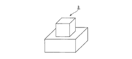
【解決手段】 ガラスによって形成された基体11の周囲にポリスチレンによって形成されたコーティング層12を有する粉末材料1を堆積することと、粉末材料1の所望の領域に対してリモネンを供給した後に乾燥させることにより所望の領域の粉末材料1を結合させることとを繰り返し、最後に結合していない粉末材料1を除去することによって、立体造形物3を製造する。
【選択図】 図1
PROBLEM TO BE SOLVED: To provide a three-dimensional modeled object which is produced by repeatedly depositing a powder material using a resin and bonding the deposited powder material after dissolving it with a solvent, and having no warp or sink mark. .
SOLUTION: A powder material 1 having a coating layer 12 made of polystyrene is deposited around a substrate 11 made of glass, and limonene is supplied to a desired region of the powder material 1 and then dried. Then, the solid material 3 is manufactured by repeatedly combining the powder material 1 in a desired region and finally removing the powder material 1 that is not bonded.
[Selection] Figure 1
Description
本発明は、立体造形方法及び立体造形物に関し、詳しくは、粉末材料を堆積させることと、堆積させた粉末材料を結合させることとを繰り返して立体造形物を造形する立体造形方法、並びにかかる立体造形方法で造形された立体造形物に関する。 The present invention relates to a three-dimensional modeling method and a three-dimensional modeling object, and more specifically, a three-dimensional modeling method for modeling a three-dimensional modeling object by repeatedly depositing a powder material and combining the deposited powder materials, and the three-dimensional modeling method. The present invention relates to a three-dimensional modeled object modeled by a modeling method.
従来から、粉末材料を堆積させることと、堆積させた粉末材料を結合させることとを繰り返すことによって、工具や部品など複雑な形状をした立体造形物を造形するための立体造形方法が知られている。 Conventionally, there has been known a three-dimensional modeling method for modeling a three-dimensional object having a complicated shape such as a tool or a part by repeatedly depositing a powder material and combining the deposited powder material. Yes.
具体例としては、例えば、でんぷんの粉末や石膏の粉末などを堆積させることと、堆積させた粉末などに接着剤を噴射してでんぷんの粉末や石膏の粉末などを結合させることとを繰り返して、立体造形物を造形する方法、並びに、金属材料の粉末を堆積させることと、堆積させた金属材料の粉末に対してレーザ光を照射することにより金属材料の粉末を溶解させた後に結合させることとを繰り返して、立体造形物を造形する方法などが挙げられる。 As a specific example, for example, it is repeated to deposit starch powder or gypsum powder, and to bond the starch powder or gypsum powder by spraying an adhesive on the deposited powder, A method of modeling a three-dimensional structure, and depositing a powder of a metal material; and bonding after dissolving the powder of the metal material by irradiating the deposited metal material powder with laser light And a method of modeling a three-dimensional model.
ところが、でんぷんの粉末や石膏の粉末によって造形された立体造形物は、粉末同士の結合力が弱いために、造形された立体造形物に対して結合増強液を含浸させて粉末同士の結合力を向上させる必要が生じる。したがって、でんぷんの粉末や石膏の粉末によって立体造形物を造形する場合には、立体造形物に結合増強液を含浸させる工程が加わるために、煩雑な作業が増えてしまう。 However, since the three-dimensional structure formed with starch powder or gypsum powder has a weak bonding force between the powders, the three-dimensional structure formed is impregnated with a binding enhancement liquid to increase the bonding force between the powders. Need to improve. Therefore, in the case of modeling a three-dimensional model using starch powder or gypsum powder, a step of impregnating the three-dimensional model with a binding enhancing liquid is added, so that complicated work increases.
また、金属材料の粉末によって造形された立体造形物は、金属粉末が独特の濃灰色であるために、着色している。したがって、金属材料の粉末によって立体造形物を造形する場合には、得られる立体造形物を所望の色とすることが困難となる。さらに、金属材料の粉末によって立体造形物を造形する場合には、使用される装置が高額であるために、造形にかかるコストが高くなる。 In addition, the three-dimensional modeled object modeled with the powder of the metal material is colored because the metal powder is a unique dark gray color. Therefore, when modeling a three-dimensional molded object with the powder of a metal material, it becomes difficult to make the obtained three-dimensional molded object into a desired color. Furthermore, when modeling a three-dimensional molded object with the powder of a metal material, since the apparatus used is expensive, the cost concerning modeling becomes high.
以上説明した問題点を回避する方法としては、樹脂の粉末を堆積させることと、堆積させた粉末の所定の領域に対して樹脂を溶解させる溶剤を噴射して、樹脂の粉末を溶解させた後に固化することによって結合させることとを繰り返すことにより、立体造形物を造形する方法が挙げられる。かかる造形方法によって製造した立体造形物は、結合力が強く、着色もなく、また造形にかかるコストが抑えられたものとなる。 As a method for avoiding the above-described problems, resin powder is deposited, and after a resin solvent is injected into a predetermined region of the deposited powder, the resin powder is dissolved. The method of modeling a three-dimensional molded item by repeating combining by solidifying is mentioned. A three-dimensional model manufactured by such a modeling method has a strong bonding force, no coloration, and a low cost for modeling.
しかしながら、樹脂は、溶解して固化するときに収縮する。したがって、樹脂の粉末を堆積させることと、堆積させた粉末の所定の領域に対して樹脂を溶解させる溶剤を噴射して、樹脂の粉末を溶解させた後に固化することによって結合させることとを繰り返して立体造形物を造形する場合には、得られた立体造形物に、立体造形物全体が湾曲する反りや、立体造形物の一主面が陥没するヒケなどが生じてしまう。したがって、所望のサイズや形状の立体造形物を造形することが困難となる。 However, the resin shrinks when dissolved and solidified. Therefore, the resin powder is repeatedly deposited and the solvent is dissolved in a predetermined region of the deposited powder, and the resin powder is dissolved and then solidified and then combined. In the case of modeling a three-dimensional model, the resulting three-dimensional model has warping that the entire three-dimensional model is curved, sink marks where one main surface of the three-dimensional model is depressed, and the like. Therefore, it becomes difficult to form a three-dimensional object having a desired size and shape.
反りやヒケを低減させる方法としては、樹脂の粉末にガラスの粉末を最適な比率で混合した粉末材料を堆積させることと、堆積させた粉末材料の所定の領域に対して樹脂を溶解させる溶剤を噴射して、樹脂の粉末を溶解させた後に固化することで結合させることとを繰り返して立体造形物を造形する方法が挙げられる。しかし、樹脂の粉末中にガラスの粉末を均一に混合させることは困難である。したがって、樹脂の粉末にガラスの粉末を混合させた粉末材料によって立体造形物を造形した場合にも、反りやヒケを十分に低減させることは困難となる。 As a method for reducing warping and sink marks, a powder material in which glass powder is mixed with resin powder in an optimum ratio is deposited, and a solvent for dissolving the resin in a predetermined region of the deposited powder material is used. There is a method of forming a three-dimensional model by repeating injection and dissolving after dissolving resin powder and solidifying. However, it is difficult to uniformly mix the glass powder into the resin powder. Therefore, it is difficult to sufficiently reduce warpage and sink marks even when a three-dimensional object is formed with a powder material in which glass powder is mixed with resin powder.
本発明は、以上説明した従来の実情を鑑みて提案されたものであり、樹脂を使用して作成された粉末材料を強く結合させることにより、強度が十分で且つ反りやヒケがなく、また着色もない立体造形物を製造するための立体造形法、並びに、樹脂を使用して作成された粉末材料を溶剤によって溶解した後に強く結合させることによって造形されており、強度が十分で且つ反りやヒケがなく、また着色もない立体造形物を提供することを目的とする。 The present invention has been proposed in view of the above-described conventional situation. By strongly bonding a powder material prepared using a resin, the strength is sufficient, and there is no warp or sink, and coloring. 3D modeling method for manufacturing a 3D model, and a powder material made using a resin is strongly bonded after being dissolved with a solvent, and has sufficient strength and has sufficient warpage and sink marks. The object is to provide a three-dimensionally shaped object that is free from coloring and is not colored.
本発明に係る立体造形方法は、基体を樹脂で被覆することによって形成された粉末材料を堆積させ、堆積させた上記粉末材料の所定の領域に上記樹脂を溶解させる溶剤を供給し、供給された上記溶剤によって溶解された樹脂を固化させることにより、上記粉末材料を結合させることを特徴とする。 In the three-dimensional modeling method according to the present invention, a powder material formed by coating a substrate with a resin is deposited, and a solvent for dissolving the resin is supplied to a predetermined region of the deposited powder material, and then supplied. The powder material is bonded by solidifying the resin dissolved by the solvent.
したがって、本発明に係る立体造形方法によれば、粉末材料の樹脂を溶剤によって溶解した後に、収縮させずに強力に結合させることが可能となる。 Therefore, according to the three-dimensional modeling method according to the present invention, after the resin of the powder material is dissolved by the solvent, it can be strongly bonded without being contracted.
また、本発明に係る立体造形装置は、基体を樹脂で被覆することによって形成された粉末材料からなり、上記樹脂を溶剤で溶解して固化することにより、上記粉末材料を結合して造形される。 Further, the three-dimensional modeling apparatus according to the present invention is made of a powder material formed by coating a base with a resin, and is formed by combining the powder material by dissolving and solidifying the resin with a solvent. .
したがって、本発明に係る立体造形物は、樹脂を使用した粉末材料によって造形されており、且つ収縮が少ないものとなる。 Therefore, the three-dimensional modeled object according to the present invention is modeled with a powder material using a resin, and has little shrinkage.
本発明に係る立体造形方法は、樹脂を使用して作成された粉末材料を溶剤によって溶解した後に、収縮させずに結合させることが可能となるために、樹脂材料が使用されており、且つ反りやヒケなどが生じにくく、正確なサイズの立体造形物を造形することが可能となる。また、樹脂が溶解した後に固化することによって各粉末材料を結合させるために、各粉末材料を強く結合させて、丈夫で破壊されにくい立体造形物を造形することが可能となる。 In the three-dimensional modeling method according to the present invention, a resin material is used and warping is possible because a powder material prepared using a resin can be bonded without being contracted after being dissolved by a solvent. This makes it possible to form a three-dimensional object with an accurate size. In addition, since the powder materials are bonded by solidifying after the resin is dissolved, the powder materials can be strongly bonded to form a solid three-dimensional object that is hard to break.
本発明に係る立体造形物は、樹脂を使用して作成された粉末材料を溶剤によって溶解した後に、収縮させずに結合させることによって造形されているために、樹脂材料が使用されているにも拘わらず、反りやヒケなどが生じにくく、正確な大きさとなる。また、樹脂を溶解させた後に固化することによって各粉末材料が結合されているために、丈夫で破壊されにくいものとなる。 Since the three-dimensionally shaped object according to the present invention is formed by dissolving a powder material made using a resin with a solvent and then bonding it without contracting, the resin material is also used. Regardless, warp and sink marks are less likely to occur and the size is accurate. Moreover, since each powder material is couple | bonded by solidifying after melt | dissolving resin, it will become strong and hard to be destroyed.
以下、本発明を実施するための最良の形態について、図面を参照しながら詳細に説明する。 Hereinafter, the best mode for carrying out the present invention will be described in detail with reference to the drawings.
本発明を適用した立体造形方法では、粉末を堆積させることと、目的とする立体造形物の断面と同じ形状である所定の領域に対して溶剤を供給することと、溶剤が供給された領域を乾燥させることとを繰り返す。 In the three-dimensional modeling method to which the present invention is applied, the powder is deposited, the solvent is supplied to a predetermined region having the same shape as the cross section of the target three-dimensional model, and the region where the solvent is supplied Repeat with drying.
具体的に説明すると、図1(A)に示すように粉末材料1を堆積し、次に、図1(B)に示すように粉末材料1の所定の領域Aに対して溶剤2を供給し、次に、図1(C)に示すように溶剤2が供給された所定の領域Aを乾燥させることで所定の領域Aの粉末材料1を結合させる。そして、図1(D)に示すように更に粉末材料1を堆積し、図1(E)に示すように再度所定の領域Aに対して溶剤2を供給し、図1(F)に示すように再度所定の領域Aを乾燥させる。
More specifically, the
溶剤2を供給する領域は、断面の形状に応じて変化する。例えば、断面積が狭くなるときには、図1(G)に示すように更に粉末材料1を堆積させた後に、図1(H)に示すように所定の領域Aよりも狭い所定の領域Bに対して溶剤2を供給し、図1(I)に示すように所定の領域Bを乾燥させる。
The area | region which supplies the solvent 2 changes according to the shape of a cross section. For example, when the cross-sectional area becomes narrower, after the
そして、最後に結合していない粉末材料1を除去することによって、例えば図2に示すように、大きさの異なる2つの立方体が重ねられている立体造形物3が造形される。
Then, by removing the
1回に堆積される粉末材料1の厚さTは、最終的に製造される立体造形物3の形状の複雑さなどによって決定され、例えば100μmとされる。
The thickness T of the
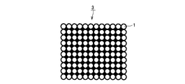
粉末材料1は、図3に示すように、基体11の周囲にコーティング層12が形成されてなる。
As shown in FIG. 3, the
基体11の粒径は、1μm〜20μm程度とされていることが好ましく、1〜10μmとされていることが更に好ましい。また、コーティング層12の厚さは、0.5μm〜1μm程度とされることが好ましい。
The particle diameter of the
粉末材料1の粒径が大きすぎると、目的とする立体造形物3の形状が複雑であるときなどに、正確に形成することが困難となり、加工精度が低下する。また、粒径が小さすぎると、後述する立体造形装置の隙間に粉末材料1が入りこんでしまうなどの理由により、立体造形に支障が生じてしまう。
If the particle size of the
基体11は、溶剤2によって溶解されない材料によって形成される。基体11は、ガラス及びセラミックによって形成されることが好ましい。基体11をガラス及びセラミックによって形成することにより、粉末材料1は白色となり、最終的に得られた立体造形物3に対して所望の着色を施すことが可能となる。また、基体11をガラス及びセラミックによって形成することにより、製造された立体造形物3は、密度が1.3g/cm3程度となるために、重量感を有するものとなる。また、基体11は、ガラスによって形成されることが最も好ましい。基体11をガラスによって形成することにより、粉末材料1を作成するときにかかるコストを抑えることが可能となる。
The
なお、粉末材料1が着色されていても良い場合には、基体11は、鉱物、岩石、金属、フッ素ゴムなどによって形成されていても良い。また、造形される立体造形物3の質量を軽くする場合には、基体11は、塩、小麦粉、砂糖、でんぷん、溶剤2により変質しない樹脂などによって形成されていても良い。
In addition, when the
すなわち、本発明によれば、粉末材料1の基体11の材料を変えることで、立体造形物3の色を変えることや、立体造形物3を所望の質量とすることなどが可能となる。
That is, according to the present invention, it is possible to change the color of the three-
コーティング層12は、溶剤2によって溶解される樹脂によって形成され、例えば、ポリスチレンやポリプロピレンなどによって形成される。コーティング層12の厚さは、例えば1μmとされる。
The
コーティング層12が溶剤2によって溶解することで、各粉末材料1のコーティング層12に使用されている樹脂が混ざり合う。そして、樹脂が混ざり合った状態で固化するために、基体11が固化された樹脂によって固定される。すなわち、コーティング層12が、粉末材料1を結合させるバインダとなる。
As the
溶剤2としては、コーティング層12を溶解し、基体11を溶解しないものが使用される。具体例を挙げると、基体11がガラスによって形成されておりコーティング層12がポリスチレンによって形成されている場合にはリモネンが使用され、基体11がガラスによって形成されておりコーティング層12がポリプロピレンによって形成されている場合にはトルエンが使用される。
As the solvent 2, a solvent that dissolves the
溶剤2としては、リモネンを使用することが最も好ましい。リモネンは、安全性が高く取り扱いが容易であるために、溶剤2としてリモネンを使用することにより、立体造形物3を、安全且つ簡易に造形することが可能となる。
As the solvent 2, it is most preferable to use limonene. Since limonene is highly safe and easy to handle, the use of limonene as the solvent 2 makes it possible to form the three-
溶剤2としてリモネンを使用することが最も好ましいために、コーティング層12は、リモネンによって溶解される樹脂によって形成されることが好ましい。リモネンによって溶解される樹脂としては、ポリスチレンが挙げられる。すなわち、コーティング層12は、ポリスチレンによって形成されることが最も好ましい。基材11をガラスによって形成し、コーティング層12をポリスチレンによって形成することにより、得られる立体造形物3は、製造にかかるコストが低減されたものとなる。
Since it is most preferable to use limonene as the solvent 2, the
以上説明したように、本発明を適用した立体造形物の製造方法によれば、基体11の周囲に樹脂によってコーティング層12を形成した粉末材料1を堆積させることと、粉末材料1の所定の領域に対して溶剤2を噴射してコーティング層12を溶解させることと、溶剤2が噴射された領域を乾燥させて溶解した樹脂を固化させることによって粉末材料1を結合させることとを繰り返しながら、立体造形物3が造形される。
As described above, according to the method for manufacturing a three-dimensional structure to which the present invention is applied, the
得られた立体造形物3は、図4に示すように、各基体11が、コーティング層12に使用されている樹脂によって固定されてなる。基体11が樹脂によって固定されることにより、樹脂が固化するときに生じる立体造形物2の収縮が低減される。したがって、本発明を適用した立体造形物3は、樹脂によって造形されており、且つ反りやヒケがなく、寸法が正確なものとなる。
As shown in FIG. 4, the obtained three-
また、立体造形物3は、コーティング層12として使用されているポリスチレンが溶剤によって溶解されて混ざり合った後に固化することによって造形されるために、粉末材料1が互いに強く結合し、強度が十分で破壊されにくいものとなる。
In addition, since the three-
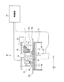
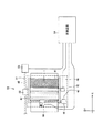
つぎに、図5及び図6に示すような、立体造形物3を製造するときに使用する立体造形装置30について説明する。なお、図5は立体造形装置30の側面図であり、図6は立体造形装置30の平面図である。
Next, a three-
立体造形装置30は、主面上に粉末材料1が堆積される造形テーブル31と、造形テーブル31を上下方向に移動させるテーブル駆動モータ32と、内壁が造形テーブル31の側面に接触しているシリンダ33とを備える。
The three-
また、立体造形装置30は、粉末材料1が貯えられており、造形テーブル31上に粉末材料1を供給する粉末バケット41と、造形テーブル31上に供給された粉末材料1を平坦化するローラ42と、ローラ42を駆動するローラ駆動モータ43と、溶剤2が貯えられている溶剤タンク44と、ローラ42によって平坦化された粉末材料1に対して溶剤2を噴射するインクジェットヘッド45と、インクジェットヘッド45を駆動するインクジェットヘッド駆動モータ46と、インクジェットヘッド45によって溶剤2が噴射された粉末材料1に対して熱を与えるヒータ47とが設けられた供給ユニット48を備える。
The three-
また、立体造形装置30は、溶剤バケット41、ローラ42、インクジェットヘッド45が並んだ方向に沿って設けられている軸51と、供給ユニット48を軸51の方向に沿って移動可能に支持する支持部材52と、供給ユニット48全体を軸51の方向に沿って移動させる供給ユニット駆動モータ53とを備える。
The three-
また、立体造形装置30は、テーブル駆動モータ32、ローラ駆動モータ43、インクジェットヘッド駆動モータ46、ヒータ47、及び供給ユニット駆動モータ53を駆動させる制御装置54を備える。
The three-
なお、以下では、軸51の方向に沿った方向、すなわち供給ユニット48の移動方向をX方向といい、軸51に対して垂直で且つ造形テーブル31の主面に沿った方向をY方向という。
Hereinafter, the direction along the direction of the
粉末バケット41は、X方向に移動しながら、造形テーブル31と対向する位置に設けられた吐出口41aから貯えている粉末材料1を吐出して、造形テーブル31上に供給する。吐出口41aは、長方形であり、Y方向の長さが造形テーブル31と略同一とされている。また、粉末バケット41の吐出口41aには、粉末パケット弁41bが設けられており、吐出口41aから吐出される粉末材料1の量や、吐出口41aから粉末材料1が吐出するときの速度などが制御される。
The
ローラ42は、回転しながらX方向に移動し、造形テーブル31上に堆積されている粉末材料1を平坦化して、シリンダ33の供給ユニット48との対抗面、すなわち、シリンダ33の上面33aと同一平面とする。ローラ42によって粉末材料1が平坦化されることにより、厚さTの粉末材料1が造形テーブル31上に堆積する。また、ローラ42は、ローラ駆動モータ43によって駆動されることで回転する。本実施の形態では、ローラ42は、1秒当たり約6回転しながら毎分1mの速度で移動する。
The
インクジェットヘッド45は、図7(A)に示すように、多数のノズル45aが設けられており、後述するスライスデータに従って、溶剤タンク44に貯えられている溶剤を噴射し、造形テーブル31に堆積されている粉末材料1の所望の領域に、溶剤を供給する。
As shown in FIG. 7A, the
本実施の形態では、インクジェットヘッド45は、ノズル45a間のY方向に沿った間隔が0.07mmとなるように設けられている。ノズル45a間の間隔が0.07mm以上であるときには、インクジェットヘッド45を、図7(B)に示すように、ノズル45aが配置されている方向がX方向に対して傾くように設置することにより、ノズル45a間のY方向に沿った間隔は0.07mm以下となる。立体造形装置30では、インクジェットヘッド45が、ノズル45a間のY方向に沿った間隔が0.07mmとなるように設けられることにより、所望の領域全体に均一に溶剤2を噴射することが可能となる。
In the present embodiment, the
また、本実施の形態では、ノズル45aの密度は360dpiとされている。ノズル45aの密度が360dpiとされており、溶剤2としてリモネンを使用する場合には、各ノズル45aから噴射されるリモネンの量は、40pl〜80plとされることが好ましい。各ノズル45aから噴射されるリモネンの量が40pl未満である場合には、リモネンの量が不充分であるために、粉末材料1の所望の領域全体にリモネンを噴射することが不可能となる。また、80plを超える場合には、リモネンの量が多すぎるために、リモネンが噴射された後に粉末材料1が固化するまでに時間を要する。
In the present embodiment, the density of the
なお、各ノズル45aから噴射されるリモネンの量は、粉末材料1の堆積回数が増加するに従って、増加することが好ましい。例えば、1層目に堆積させた粉末材料1の所定の領域にリモネンを噴射させるときには、各ノズル45aから噴射されるリモネンの量を40plとして、徐々に増やしていくことが好ましい。量を徐々に増やしながらリモネンを噴射することにより、粉末材料1が効率良く固化される。
Note that the amount of limonene sprayed from each
また、本実施の形態では、インクジェットヘッド45は、ピエゾ方式によって溶剤2を噴射する構成とされている。ピエゾ方式を採用することにより、水溶性ではないリモネンを、溶剤2として噴射することが可能となる。
In the present embodiment, the
ヒータ47は、粉末材料1に溶剤2が噴射された後に駆動され、粉末材料1全体に熱を加えることにより、粉末材料1を乾燥させ、溶剤2によって溶解されたコーティング層12を固化し、粉末材料1を互いに結合させる。
The
制御装置54は、CAD(Computer-Aided Design)により作成されることや、特定の物品を三次元測定機で測定することなどによって得られた三次元データを、平行に薄くスライスした場合の各層のデータ(以下、スライスデータという。)を生成して、インクジェットヘッド45に対して供給する。また、テーブル駆動モータ32、ローラ駆動モータ43、インクジェットヘッド駆動モータ46、及び供給ユニット駆動モータ51を駆動して、立体造形物3を製造する。
The
具体的には、制御装置54は、供給ユニット駆動モータ53を駆動させることによって、供給ユニット48全体を、X方向に沿ってシリンダ33の内壁の一方33bから他方33cに移動させる。制御装置54の制御に基づいて、供給ユニット駆動モータ53によって駆動されることにより、供給ユニット48は、粉末バケット41に貯えられている粉末材料1を造形テーブル31上に堆積させてローラ42で平坦化した後に溶剤2を噴射するときと、溶剤2の噴射が終了した後にヒータ47によって粉末材料1を加熱するときに移動する。
Specifically, the
また、制御装置54は、ローラ駆動モータ43を駆動させることによってローラ42の回転を制御する。ローラ42の回転が制御されることによって、造形テーブル31の主面31a上に堆積された粉末材料1の平坦化が円滑になされる。
The
また、制御装置54は、インクジェットヘッド駆動モータ46を駆動して、インクジェットヘッド45を、所望の位置に移動させる。
Further, the
また、制御装置54は、1層分のスライスデータに基づいた溶剤2の噴射が終了する毎に、ヒータ47を駆動させながら供給ユニット駆動モータ53を駆動させることで供給ユニット48をX方向に沿って移動させ、粉末材料1を加熱して乾燥させる。そして、粉末材料1の乾燥が終了すると、供給ユニット48全体を、シリンダ33の内壁の一方33b側に移動させる。
The
また、制御装置54は、粉末材料1の平坦化が終了する毎に、テーブル駆動モータ32を制御して、造形テーブル31の位置を下げる。具体的には、造形テーブル31は、粉末材料1の平坦化が終了したときに、主面31aに堆積される粉末材料1の厚さTと同じだけ下げられる。
Moreover, the
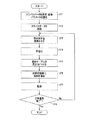
つぎに、立体造形装置30を使用した立体造形方法について、図8に示すフローチャートを使用して説明する。
Next, a three-dimensional modeling method using the three-
先ず、ステップST1で、制御装置54は、三次元データからスライスデータを作成して格納する。また、制御装置54は、例えば供給ユニット48の移動速度、単位時間当たりのローラ42の回転数、及び造形テーブル31の降下幅など、立体造形装置30の駆動に必要となるパラメータを設定したり、スライスデータの変換などを行う。
First, in step ST1, the
次に、ステップST2で、制御装置54は、インクジェットヘッド45に対して、スライスデータを送信する。
Next, in step ST <b> 2, the
そして、ステップST3で、制御装置54は、供給ユニット駆動モータ53を駆動させることにより、供給ユニット48のX方向への移動を開始して、造形テーブル31上に、粉末材料1を堆積させる。
In step ST <b> 3, the
次に、ステップST4で、制御装置54は、ローラ駆動モータ43を駆動させることにより、ローラ42を回転させて、造形テーブル31上の粉末材料1を平坦化し、粉末材料1とシリンダ33の上面33aを同一平面とする。ローラ42によって平坦化されることにより、造形テーブル31上に厚さTの粉末材料1が積層される。
Next, in step ST <b> 4, the
次に、ステップST5で、制御装置54は、テーブル駆動モータ32を駆動させることにより、造形テーブル8を厚さT分下げる。
Next, in step ST5, the
次に、ステップST6で、制御装置54は、インクジェットヘッド駆動モータ46を駆動させることによってインクジェットヘッド45の位置を移動させる。インクジェットヘッド45は、1層分のスライスデータに基づいて、粉末材料1の所定の領域に溶剤2を噴射する。溶剤2が噴射された領域では、粉末材料1の表面に形成されているコーティング層12が溶解して混ざり合う。
Next, in step ST6, the
次に、ステップST7で、制御装置54は、ヒータ47を駆動させるとともに、供給ユニット駆動モータ53を駆動させることで供給ユニット48全体をX方向に沿って移動させることにより、粉末材料1に熱を加え、粉末材料1を乾燥させる。粉末材料1が乾燥することにより、溶剤2によって溶解されたコーティング層12が固化し、粉末材料1が結合する。
Next, in step ST7, the
次に、ステップST8で、制御装置54は、立体造形が終了したか否かを判断する。立体造形が終了していないときには、ステップST3に戻り、立体造形が終了したと判断したときには立体造形装置30全体の駆動を停止させる。
Next, in step ST8, the
つぎに、本発明を適用した立体造形方法及び立体造形物について、実施例及び比較例に基づいて説明する。
実施例1
図9に示すように、粒形6μmのガラスビーズ61の周囲に、厚さ1μmのポリスチレン層62を形成することにより、粉末材料63を作成した。
Next, a three-dimensional modeling method and a three-dimensional modeled object to which the present invention is applied will be described based on examples and comparative examples.
Example 1
As shown in FIG. 9, a powder material 63 was prepared by forming a
この粉末材料63を粉末バケット41に投入し、溶剤タンク44にD−リモネンを投入して、立体造形装置30を駆動させた。
The powder material 63 was charged into the
そして、粉末材料63を造形テーブル31上に100μm堆積させることと、堆積させた粉末材料63内の30mm×10mmの領域にD−リモネンを噴射することと、D−リモネンを噴射した領域を乾燥させて粉末材料61を互いに結合させることとを10回繰り返して、30mm×10mm×1mmである平板状の立体造形物を造形した。
実施例2
図9に示す粉末材料63を粉末バケット41に投入し、溶剤タンク44にD−リモネンを投入して、立体造形装置30を駆動させた。
Then, 100 μm of the powder material 63 is deposited on the modeling table 31, D-limonene is sprayed on a 30 mm × 10 mm region in the deposited powder material 63, and the region where D-limonene is sprayed is dried. Then, the
Example 2
The powder material 63 shown in FIG. 9 was put into the
そして、粉末材料63を造形テーブル31上に100μmずつ堆積させることと、堆積させた粉末材料63内の一辺が10mmの領域に、D−リモネンを噴射することと、D−リモネンを噴射した領域を乾燥させて粉末材料61を互いに結合させることとを100回繰り返して、一辺が10mmの立方体形状の立体造形物を造形した。
比較例1
図9に示す粉末材料63の代わりに、ポリスチレンのみからなる粉末材料を作成して使用した以外は、実施例1と同様にして、30mm×10mm×1mmである平板状の立体造形物を造形した。
比較例2
図9に示す粉末材料63の代わりに、ポリスチレンのみからなる粉末材料を作成して使用した以外は、実施例2と同様にして、一辺が10mmの立方体形状の立体造形物を造形した。
Then, the powder material 63 is deposited on the modeling table 31 by 100 μm, D-limonene is sprayed on a region where one side of the deposited powder material 63 is 10 mm, and the region where D-limonene is sprayed. The process of drying and bonding the
Comparative Example 1
Instead of the powder material 63 shown in FIG. 9, a plate-shaped three-dimensional model having a size of 30 mm × 10 mm × 1 mm was formed in the same manner as in Example 1 except that a powder material made only of polystyrene was used. .
Comparative Example 2
Instead of the powder material 63 shown in FIG. 9, a cubic three-dimensional model having a side of 10 mm was modeled in the same manner as in Example 2 except that a powder material made only of polystyrene was used.
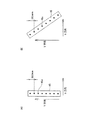
実施例1及び比較例2で造形された立体造形物について、反り、収縮率、密度を測定したところ、表1に示す通りとなった。なお、反りは、図10(A)に示すように、実施例1又は比較例1で造形された立体造形物70の上面の最も反り上がっている端部70a,70bを結んだ線L1から、上面の最も凹んだ部分70cまでの長さD1を測定することによって示した。
About the three-dimensional molded item modeled in Example 1 and Comparative Example 2, the warpage, shrinkage rate, and density were measured, and as shown in Table 1. In addition, as shown to FIG. 10 (A), curvature is from the line L1 which connected the

また、実施例2及び比較例2で造形された立体造形物について、ヒケ、収縮率、密度を測定したところ、表1に示す通りとなった。なお、ヒケは、図10(B)に示すように、実施例2又は比較例2で造形された立体造形物71の上面の最も反り上がっている端部71a,71bを結んだ線L2から、上面の最も凹んだ部分71cまでの長さD2を測定することによって示した。
Moreover, about the solid modeling thing modeled in Example 2 and Comparative Example 2, when sink marks, shrinkage rate, and density were measured, it became as shown in Table 1. In addition, as shown in FIG. 10 (B), sink marks are formed from a line L2 connecting
表1及び表2より、実施例1及び実施例2で造形された立体造形物は、比較例1及び比較例2で造形された立体造形物と比較して、収縮率が低く、反りやヒケが生じにくいものであることが確認された。また、実施例1及び実施例2で造形された立体造形物は、比較例1及び比較例2で造形された立体造形物と比較して、質量が重く、重量感を有するものであることが確認された。 From Table 1 and Table 2, the three-dimensional object modeled in Example 1 and Example 2 has a lower shrinkage rate than the three-dimensional object modeled in Comparative Example 1 and Comparative Example 2, and warps and sink marks. It was confirmed that is difficult to occur. In addition, the three-dimensional modeled object modeled in Example 1 and Example 2 is heavier than the three-dimensional modeled object modeled in Comparative Example 1 and Comparative Example 2, and has a heavy feeling. confirmed.
1 粉末材料、2 溶剤、3 立体造形物、11 基体、12 コーティング層、30 立体造形装置、31 造形テーブル、32 テーブル駆動モータ、33 シリンダ、41 粉末バケット、42 ローラ、43 ローラ駆動モータ、44 溶剤タンク、45 インクジェットヘッド、46 インクジェットヘッド駆動モータ、47 ヒータ、48 供給ユニット、51 軸、52 支持部材、53 駆動モータ、54 制御装置
DESCRIPTION OF
Claims (12)
The three-dimensional structure according to claim 10, wherein the base is made of ceramic.
Priority Applications (1)
| Application Number | Priority Date | Filing Date | Title |
|---|---|---|---|
| JP2004115767A JP2005297325A (en) | 2004-04-09 | 2004-04-09 | 3D modeling method and 3D model |
Applications Claiming Priority (1)
| Application Number | Priority Date | Filing Date | Title |
|---|---|---|---|
| JP2004115767A JP2005297325A (en) | 2004-04-09 | 2004-04-09 | 3D modeling method and 3D model |
Publications (1)
| Publication Number | Publication Date |
|---|---|
| JP2005297325A true JP2005297325A (en) | 2005-10-27 |
Family
ID=35329468
Family Applications (1)
| Application Number | Title | Priority Date | Filing Date |
|---|---|---|---|
| JP2004115767A Withdrawn JP2005297325A (en) | 2004-04-09 | 2004-04-09 | 3D modeling method and 3D model |
Country Status (1)
| Country | Link |
|---|---|
| JP (1) | JP2005297325A (en) |
Cited By (27)
| Publication number | Priority date | Publication date | Assignee | Title |
|---|---|---|---|---|
| JP2008105269A (en) * | 2006-10-25 | 2008-05-08 | Hirokazu Mizumoto | Schedule calendar |
| WO2009145069A1 (en) * | 2008-05-26 | 2009-12-03 | ソニー株式会社 | Shaping apparatus and shaping method |
| JP2010052331A (en) * | 2008-08-29 | 2010-03-11 | Nagano Japan Radio Co | Three dimensional shaping machine |
| JP2010052330A (en) * | 2008-08-29 | 2010-03-11 | Nagano Japan Radio Co | Three-dimensional shaping machine |
| WO2015046629A1 (en) | 2013-09-30 | 2015-04-02 | Ricoh Company, Ltd. | Powder material for three-dimensional object formation, hardening liquid and three-dimensional object formation kit, and formation method and formation apparatus of three-dimensional object |
| WO2015194399A1 (en) * | 2014-06-18 | 2015-12-23 | 株式会社放電精密加工研究所 | 3d molding device |
| JP2016137697A (en) * | 2015-01-27 | 2016-08-04 | 株式会社リコー | Three-dimensional molding apparatus, production method of three-dimensional molded object, and program |
| JP2016155362A (en) * | 2015-02-20 | 2016-09-01 | 株式会社リコー | 3D modeling apparatus, 3D molding method, program |
| EP3069801A2 (en) | 2015-03-19 | 2016-09-21 | Ricoh Company, Ltd. | Liquid material for forming three-dimensional object and material set for forming three-dimensional object, three-dimensional object producing method and three-dimensional object producing apparatus |
| EP3070136A1 (en) | 2015-03-19 | 2016-09-21 | Ricoh Company, Ltd. | Liquid material for forming three-dimensional object and material set for forming three-dimensional ojbect, three-dimensional object producing method and three-dimensional object producing apparatus |
| JP2016172429A (en) * | 2015-03-18 | 2016-09-29 | 株式会社リコー | Powder material for three-dimensional molding, three-dimensional molding kit, apparatus for manufacturing three-dimensional molded object, and method for manufacturing three-dimensional molded object |
| JP2016172416A (en) * | 2015-03-18 | 2016-09-29 | 株式会社リコー | Powder material for three-dimensional molding, three-dimensional molding material set, apparatus for manufacturing three-dimensional molded object, and method for manufacturing three-dimensional molded object |
| JP2016187918A (en) * | 2015-03-30 | 2016-11-04 | 株式会社リコー | Three-dimensional modeling powder material, three-dimensional modeling kit, three-dimensional model manufacturing apparatus, and three-dimensional model manufacturing method |
| JP2016190321A (en) * | 2015-03-30 | 2016-11-10 | 株式会社リコー | Powder material for three-dimensional molding, three-dimensional molding material set, apparatus for manufacturing three-dimensional molded object, and method for manufacturing three-dimensional molded object |
| JP2016223005A (en) * | 2015-03-18 | 2016-12-28 | 株式会社リコー | Powder material for stereo molding, kit for stereo molding, green body for stereo molding, manufacturing method of stereo molded article and green body for stereo molding, manufacturing device of stereo molded article and green body for stereo molding |
| CN106457395A (en) * | 2014-01-14 | 2017-02-22 | 株式会社放电精密加工研究所 | 3d molding device |
| CN106626376A (en) * | 2016-11-07 | 2017-05-10 | 广东工业大学 | Color inkjet three-dimensional printing method |
| US9708502B2 (en) | 2014-12-18 | 2017-07-18 | Ricoh Company, Ltd. | Powder for 3D modeling, set for 3D modeling, method of manufacturing 3D object, and device for manufacturing 3D object |
| WO2017196364A1 (en) | 2016-05-13 | 2017-11-16 | Hewlett-Packard Development Company, L.P. | Material sets |
| US9994702B2 (en) | 2015-01-09 | 2018-06-12 | Ricoh Company, Ltd. | Liquid material for forming three-dimensional object and material set for forming three-dimensional object, and three-dimensional object producing method and three-dimensional object producing apparatus |
| JP2019503907A (en) * | 2016-01-21 | 2019-02-14 | スリーエム イノベイティブ プロパティズ カンパニー | Lamination process of fluoroelastomer |
| US10293555B2 (en) | 2014-12-04 | 2019-05-21 | Ricoh Company, Ltd. | Liquid material for forming three-dimensional object and material set for forming three-dimensional object, and three-dimensional object producing method |
| US10464241B2 (en) | 2015-01-27 | 2019-11-05 | Ricoh Company, Ltd. | Stereoscopic modeling apparatus, method of manufacturing stereoscopic modeled product, and non-transitory recording medium |
| EP3760344A1 (en) | 2019-07-04 | 2021-01-06 | Ricoh Company, Ltd. | Powder material for producing three-dimensional object, kit for producing three-dimensional object, and three-dimensional object producing method and apparatus |
| WO2021002479A1 (en) | 2019-07-04 | 2021-01-07 | 株式会社リコー | Method and apparatus for producing additively manufactured article, curing solution for additive manufacturing, and kit for additive manufacturing |
| JP2021020371A (en) * | 2019-07-26 | 2021-02-18 | 株式会社リコー | Resin powder for stereoscopic molding and apparatus and method for forming stereoscopic molding |
| US11407033B2 (en) | 2014-01-14 | 2022-08-09 | Hoden Seimitsu Kako Kenkyusho Co., Ltd. | Three-dimensional shaping apparatus |
-
2004
- 2004-04-09 JP JP2004115767A patent/JP2005297325A/en not_active Withdrawn
Cited By (43)
| Publication number | Priority date | Publication date | Assignee | Title |
|---|---|---|---|---|
| JP2008105269A (en) * | 2006-10-25 | 2008-05-08 | Hirokazu Mizumoto | Schedule calendar |
| EP2305454A4 (en) * | 2008-05-26 | 2013-01-09 | Sony Corp | SHAPE APPARATUS AND SHAPING METHOD |
| WO2009145069A1 (en) * | 2008-05-26 | 2009-12-03 | ソニー株式会社 | Shaping apparatus and shaping method |
| US9636870B2 (en) | 2008-05-26 | 2017-05-02 | Sony Corporation | Modeling apparatus and modeling method |
| JPWO2009145069A1 (en) * | 2008-05-26 | 2011-10-06 | ソニー株式会社 | Modeling apparatus and modeling method |
| JP2010052331A (en) * | 2008-08-29 | 2010-03-11 | Nagano Japan Radio Co | Three dimensional shaping machine |
| JP2010052330A (en) * | 2008-08-29 | 2010-03-11 | Nagano Japan Radio Co | Three-dimensional shaping machine |
| US11628617B2 (en) | 2013-09-30 | 2023-04-18 | Ricoh Company, Ltd. | Formation method of three-dimensional object with metal and/or ceramic particles and thin organic resin |
| WO2015046629A1 (en) | 2013-09-30 | 2015-04-02 | Ricoh Company, Ltd. | Powder material for three-dimensional object formation, hardening liquid and three-dimensional object formation kit, and formation method and formation apparatus of three-dimensional object |
| US10828827B2 (en) | 2013-09-30 | 2020-11-10 | Ricoh Company, Ltd. | Powder material for three-dimensional object formation, hardening liquid and three-dimensional object formation kit, and formation method and formation apparatus of three-dimensional object |
| US11407033B2 (en) | 2014-01-14 | 2022-08-09 | Hoden Seimitsu Kako Kenkyusho Co., Ltd. | Three-dimensional shaping apparatus |
| CN106457395A (en) * | 2014-01-14 | 2017-02-22 | 株式会社放电精密加工研究所 | 3d molding device |
| WO2015194399A1 (en) * | 2014-06-18 | 2015-12-23 | 株式会社放電精密加工研究所 | 3d molding device |
| US11407032B2 (en) | 2014-06-18 | 2022-08-09 | Hoden Seimitsu Kako Kenkyusho Co., Ltd. | Three-dimensional shaping apparatus |
| US10293555B2 (en) | 2014-12-04 | 2019-05-21 | Ricoh Company, Ltd. | Liquid material for forming three-dimensional object and material set for forming three-dimensional object, and three-dimensional object producing method |
| US9708502B2 (en) | 2014-12-18 | 2017-07-18 | Ricoh Company, Ltd. | Powder for 3D modeling, set for 3D modeling, method of manufacturing 3D object, and device for manufacturing 3D object |
| US9994702B2 (en) | 2015-01-09 | 2018-06-12 | Ricoh Company, Ltd. | Liquid material for forming three-dimensional object and material set for forming three-dimensional object, and three-dimensional object producing method and three-dimensional object producing apparatus |
| JP2016137697A (en) * | 2015-01-27 | 2016-08-04 | 株式会社リコー | Three-dimensional molding apparatus, production method of three-dimensional molded object, and program |
| US10464241B2 (en) | 2015-01-27 | 2019-11-05 | Ricoh Company, Ltd. | Stereoscopic modeling apparatus, method of manufacturing stereoscopic modeled product, and non-transitory recording medium |
| JP2016155362A (en) * | 2015-02-20 | 2016-09-01 | 株式会社リコー | 3D modeling apparatus, 3D molding method, program |
| JP2016172429A (en) * | 2015-03-18 | 2016-09-29 | 株式会社リコー | Powder material for three-dimensional molding, three-dimensional molding kit, apparatus for manufacturing three-dimensional molded object, and method for manufacturing three-dimensional molded object |
| JP2016223005A (en) * | 2015-03-18 | 2016-12-28 | 株式会社リコー | Powder material for stereo molding, kit for stereo molding, green body for stereo molding, manufacturing method of stereo molded article and green body for stereo molding, manufacturing device of stereo molded article and green body for stereo molding |
| JP2016172416A (en) * | 2015-03-18 | 2016-09-29 | 株式会社リコー | Powder material for three-dimensional molding, three-dimensional molding material set, apparatus for manufacturing three-dimensional molded object, and method for manufacturing three-dimensional molded object |
| US9782935B2 (en) | 2015-03-18 | 2017-10-10 | Ricoh Company, Ltd. | Powder material for three-dimensional modeling, kit for three-dimensional modeling, device for manufacturing three-dimensional object, and method of manufacturing three-dimensional object |
| EP3069801A2 (en) | 2015-03-19 | 2016-09-21 | Ricoh Company, Ltd. | Liquid material for forming three-dimensional object and material set for forming three-dimensional object, three-dimensional object producing method and three-dimensional object producing apparatus |
| EP3070136A1 (en) | 2015-03-19 | 2016-09-21 | Ricoh Company, Ltd. | Liquid material for forming three-dimensional object and material set for forming three-dimensional ojbect, three-dimensional object producing method and three-dimensional object producing apparatus |
| JP2016175212A (en) * | 2015-03-19 | 2016-10-06 | 株式会社リコー | Composition liquid for three-dimensional molding and three-dimensional molding material set, and method and apparatus for manufacturing three-dimensional molding |
| JP2016175213A (en) * | 2015-03-19 | 2016-10-06 | 株式会社リコー | Composition liquid for three-dimensional molding and three-dimensional molding material set, and method and apparatus for manufacturing three-dimensional molding |
| US10767071B2 (en) | 2015-03-19 | 2020-09-08 | Ricoh Company, Ltd. | Liquid material for forming three-dimensional object and material set for forming three-dimensional object, three-dimensional object producing method and three-dimensional object producing apparatus |
| JP2016190321A (en) * | 2015-03-30 | 2016-11-10 | 株式会社リコー | Powder material for three-dimensional molding, three-dimensional molding material set, apparatus for manufacturing three-dimensional molded object, and method for manufacturing three-dimensional molded object |
| JP2016187918A (en) * | 2015-03-30 | 2016-11-04 | 株式会社リコー | Three-dimensional modeling powder material, three-dimensional modeling kit, three-dimensional model manufacturing apparatus, and three-dimensional model manufacturing method |
| US11148361B2 (en) | 2016-01-21 | 2021-10-19 | 3M Innovative Properties Company | Additive processing of fluoroelastomers |
| JP2019503907A (en) * | 2016-01-21 | 2019-02-14 | スリーエム イノベイティブ プロパティズ カンパニー | Lamination process of fluoroelastomer |
| US11230053B2 (en) | 2016-01-21 | 2022-01-25 | 3M Innovative Properties Company | Additive processing of fluoropolymers |
| US11179886B2 (en) | 2016-01-21 | 2021-11-23 | 3M Innovative Properties Company | Additive processing of fluoropolymers |
| EP3455056A4 (en) * | 2016-05-13 | 2020-01-22 | Hewlett-Packard Development Company, L.P. | MATERIAL SETS |
| US10710301B2 (en) | 2016-05-13 | 2020-07-14 | Hewlett-Packard Development Company, L.P. | Material sets |
| WO2017196364A1 (en) | 2016-05-13 | 2017-11-16 | Hewlett-Packard Development Company, L.P. | Material sets |
| CN106626376A (en) * | 2016-11-07 | 2017-05-10 | 广东工业大学 | Color inkjet three-dimensional printing method |
| WO2021002479A1 (en) | 2019-07-04 | 2021-01-07 | 株式会社リコー | Method and apparatus for producing additively manufactured article, curing solution for additive manufacturing, and kit for additive manufacturing |
| EP3760344A1 (en) | 2019-07-04 | 2021-01-06 | Ricoh Company, Ltd. | Powder material for producing three-dimensional object, kit for producing three-dimensional object, and three-dimensional object producing method and apparatus |
| US11426929B2 (en) | 2019-07-04 | 2022-08-30 | Ricoh Company, Ltd. | Powder material for producing three-dimensional object, kit for producing three-dimensional object, and three-dimensional object producing method and apparatus |
| JP2021020371A (en) * | 2019-07-26 | 2021-02-18 | 株式会社リコー | Resin powder for stereoscopic molding and apparatus and method for forming stereoscopic molding |
Similar Documents
| Publication | Publication Date | Title |
|---|---|---|
| JP2005297325A (en) | 3D modeling method and 3D model | |
| US6036777A (en) | Powder dispensing apparatus using vibration | |
| EP1915246B1 (en) | Method for fabricating three dimensional models | |
| EP1541321B1 (en) | System and method for fabricating three-dimensional objects using solid free-form fabrication | |
| US6596224B1 (en) | Jetting layers of powder and the formation of fine powder beds thereby | |
| US5740051A (en) | 3-D model making | |
| CA2293638C (en) | Jetting layers of powder and the formation of fine powder beds thereby | |
| CN100344440C (en) | Making process of 3D color object | |
| EP0644809B1 (en) | Three-dimensional printing techniques | |
| JP4785333B2 (en) | Parts production method by deposition method | |
| CN107336437B (en) | System and method for forming an integrated interface in a three-dimensional printed article | |
| KR102021406B1 (en) | Method for producing a moulded body and device | |
| CN108367464B (en) | Method of printing on a 3D jet printer | |
| US20100021638A1 (en) | Method for fabricating three dimensional models | |
| EP1524098B1 (en) | Hybrid organic-inorganic composition for solid freeform fabrication and solid freeform fabrication method | |
| JP2017524579A (en) | Multi-material 3D printer | |
| JP2005120475A (en) | Apparatus and method for manufacturing a three-dimensional metal object | |
| CN110545939B (en) | Method and system for additive manufacturing of materials using powders | |
| JP2015189024A (en) | Manufacturing method of shaped objects | |
| JPH08192468A (en) | Method and apparatus for manufacturing three-dimensional model | |
| JP7234716B2 (en) | Powder for three-dimensional modeling, container containing powder, method for producing three-dimensional model, and apparatus for producing three-dimensional model | |
| JP2019157201A (en) | Stereo model object producing process, stereo model object producing apparatus, and stereo model object producing program | |
| US20230321723A1 (en) | Method for producing a 3d shaped article, and device using a sieve plate | |
| JP2011143475A (en) | Parts producing method by deposition method | |
| JP2023528956A (en) | A method of making 3D structures in which the speed of movement of working tools, especially squeegees, is reduced in critical areas |
Legal Events
| Date | Code | Title | Description |
|---|---|---|---|
| A300 | Application deemed to be withdrawn because no request for examination was validly filed |
Free format text: JAPANESE INTERMEDIATE CODE: A300 Effective date: 20070703 |