JP2005297212A - Inkjet recording apparatus and inkjet recording method - Google Patents
Inkjet recording apparatus and inkjet recording method Download PDFInfo
- Publication number
- JP2005297212A JP2005297212A JP2004112213A JP2004112213A JP2005297212A JP 2005297212 A JP2005297212 A JP 2005297212A JP 2004112213 A JP2004112213 A JP 2004112213A JP 2004112213 A JP2004112213 A JP 2004112213A JP 2005297212 A JP2005297212 A JP 2005297212A
- Authority
- JP
- Japan
- Prior art keywords
- recording
- recording medium
- glossiness
- ink
- combination
- Prior art date
- Legal status (The legal status is an assumption and is not a legal conclusion. Google has not performed a legal analysis and makes no representation as to the accuracy of the status listed.)
- Granted
Links
Images

Classifications
-
- G—PHYSICS
- G06—COMPUTING OR CALCULATING; COUNTING
- G06K—GRAPHICAL DATA READING; PRESENTATION OF DATA; RECORD CARRIERS; HANDLING RECORD CARRIERS
- G06K15/00—Arrangements for producing a permanent visual presentation of the output data, e.g. computer output printers
- G06K15/02—Arrangements for producing a permanent visual presentation of the output data, e.g. computer output printers using printers
- G06K15/10—Arrangements for producing a permanent visual presentation of the output data, e.g. computer output printers using printers by matrix printers
- G06K15/102—Arrangements for producing a permanent visual presentation of the output data, e.g. computer output printers using printers by matrix printers using ink jet print heads
- G06K15/105—Multipass or interlaced printing
- G06K15/107—Mask selection
-
- B—PERFORMING OPERATIONS; TRANSPORTING
- B41—PRINTING; LINING MACHINES; TYPEWRITERS; STAMPS
- B41J—TYPEWRITERS; SELECTIVE PRINTING MECHANISMS, i.e. MECHANISMS PRINTING OTHERWISE THAN FROM A FORME; CORRECTION OF TYPOGRAPHICAL ERRORS
- B41J11/00—Devices or arrangements of selective printing mechanisms, e.g. ink-jet printers or thermal printers, for supporting or handling copy material in sheet or web form
- B41J11/009—Detecting type of paper, e.g. by automatic reading of a code that is printed on a paper package or on a paper roll or by sensing the grade of translucency of the paper
Landscapes
- Physics & Mathematics (AREA)
- Engineering & Computer Science (AREA)
- Mathematical Physics (AREA)
- General Engineering & Computer Science (AREA)
- General Physics & Mathematics (AREA)
- Theoretical Computer Science (AREA)
- Ink Jet (AREA)
- Particle Formation And Scattering Control In Inkjet Printers (AREA)
- Ink Jet Recording Methods And Recording Media Thereof (AREA)
- Inks, Pencil-Leads, Or Crayons (AREA)
Abstract
【課題】 顔料インクを用いて記録を行うシリアル型のインクジェット記録装置において、光沢を有する記録媒体に対しても、記録部分の光沢性を損なわず、良好な光沢感が維持可能な記録方法を提供する。
【解決手段】 記録ヘッドを記録媒体の同一画像領域に対しN(Nは1以上の整数)回の記録走査を行うことによって画像を形成するにあたって、記録媒体の光沢度に応じて記録走査の回数やマルチパスの際の用いられるマスクパターンを設定する。これにより、記録媒体表面における、顔料インクの堆積に伴う平滑性を制御することが出来るので、それぞれの記録媒体に好適な光沢を実現することが可能となる。
【選択図】 図5PROBLEM TO BE SOLVED: To provide a recording method capable of maintaining a good gloss feeling without losing the gloss of a recording portion even for a glossy recording medium in a serial type ink jet recording apparatus which performs recording using pigment ink. To do.
When forming an image by performing a recording scan N (N is an integer of 1 or more) times for the same image area of the recording medium with the recording head, the number of recording scans according to the glossiness of the recording medium Sets the mask pattern to be used for multipass. As a result, the smoothness associated with the deposition of the pigment ink on the surface of the recording medium can be controlled, so that gloss suitable for each recording medium can be realized.
[Selection] Figure 5
Description
本発明はインクジェット記録装置に関し、特に光沢度の高い記録媒体における記録部の光沢を制御する方法に関するものである。 The present invention relates to an ink jet recording apparatus, and more particularly to a method for controlling the gloss of a recording portion in a recording medium having a high glossiness.
インクジェット記録方法は、記録液(インク)の小滴を記録素子より吐出させ、これを紙などの記録媒体に付着させて記録を行うものである。インク滴を吐出させるためのエネルギ手段としては、様々なものが挙げられるが、特に、記録素子内部に電気熱変換体を用いた構成は、高密度なマルチオリフィス化が比較的容易に実現でき、高速かつ高密度な記録を実現できることから、近年広く有用されている(特許文献1、特許文献2および特許文献3参照。)。
In the ink jet recording method, recording is performed by ejecting small droplets of recording liquid (ink) from a recording element and attaching them to a recording medium such as paper. There are various energy means for ejecting ink droplets, and in particular, the configuration using an electrothermal transducer inside the recording element can realize high-density multi-orifice relatively easily, Since high-speed and high-density recording can be realized, it has been widely used in recent years (see
従来、インクジェット記録に用いられるインクにおいては、水を主成分し、色材として、主成分である水に溶解しやすい染料を適用する場合が多かった。このような染料インクでは、色材が水分とともに記録媒体の内部まで浸透しやすいものが多い。よって、表面の平滑性が高く光沢のある媒体に記録した場合にも、媒体の表面の平滑性は維持され、十分に高い光沢を有する記録物を得ることが可能であった。従って、画像に対して光沢性を付与するための技術課題に対しては、記録媒体の改良を施すことで対応が図られていた。 Conventionally, in inks used for ink jet recording, water is the main component, and a dye that is easily dissolved in water, which is the main component, is often used as a coloring material. Many of these dye inks easily allow the color material to penetrate into the inside of the recording medium together with moisture. Therefore, even when recording is performed on a glossy medium having a high surface smoothness, the smoothness of the surface of the medium is maintained and a recorded matter having a sufficiently high gloss can be obtained. Therefore, a technical problem for imparting gloss to an image has been addressed by improving the recording medium.
ところで近年では、記録物の耐光性や耐水性を、更に向上させることへの要求が高まっており、これに答えるために、顔料を色材としたインクの開発が進められて来ている。一般に顔料インクにおいては、色材が水分とともに記録媒体の内部まで浸透しにくい場合が多い。よって、記録媒体における定着性あるいは光沢性において、対応すべき問題が提起されている。定着性については、例えばマルチパス記録を採用することによってある程度解決することが出来る。 Incidentally, in recent years, there has been an increasing demand for further improving the light resistance and water resistance of recorded matter, and in order to answer this, the development of inks using pigments as color materials has been underway. In general, in a pigment ink, it is often difficult for a color material to penetrate into the inside of a recording medium together with moisture. Therefore, a problem to be addressed has been raised in the fixing property or glossiness of the recording medium. The fixability can be solved to some extent by employing, for example, multi-pass printing.
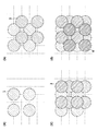
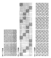
図1は、マルチパス記録を説明するための模式図である。マルチパス記録とは、一般にシリアル型のインクジェット記録装置で適用され、記録媒体の同一画像領域に対し、複数回の記録走査に分けて画像が段階的に形成されていく方法である。 FIG. 1 is a schematic diagram for explaining multi-pass printing. Multi-pass printing is a method that is generally applied to a serial type ink jet printing apparatus, and an image is formed stepwise for the same image area of a printing medium divided into a plurality of printing scans.
図において、図1(a)は、1回目の記録走査が行われた後の記録媒体の様子を示している。ここでは、1回目の記録走査で着弾されたドットを1と示し、互いに重ならない状態で記録されている例を示している。図1(b)は、2回目の記録走査が行われた後の記録媒体の様子を示している。2回目の記録走査で記録されたドットは2と示している。図1(c)は、3回目の記録走査が行われた後の、図1(d)は、4回目の記録走査が行われた後の記録媒体の様子をそれぞれ示しており、それぞれの記録走査で着弾されたドットは3および4として示している。以上4回の記録走査で同一画像領域への記録が完成している。それぞれの記録走査でどの位置への記録を可能とするかは、記録データと、マスクパターンと呼ばれる2値データとのAND処理をかけること等によって決定されている。 In FIG. 1, FIG. 1A shows the state of the recording medium after the first recording scan is performed. Here, the dot landed in the first recording scan is indicated as 1, and an example is shown in which the dots are recorded in a state where they do not overlap each other. FIG. 1B shows a state of the recording medium after the second recording scan is performed. The dot recorded in the second printing scan is indicated as 2. FIG. 1C shows the state of the recording medium after the third recording scan, and FIG. 1D shows the state of the recording medium after the fourth recording scan. Dots landed by scanning are shown as 3 and 4. The recording in the same image area is completed by the above four recording scans. Which position can be recorded in each recording scan is determined by performing an AND process on the recording data and binary data called a mask pattern.
マルチパス記録においては、各記録走査の間に記録媒体の搬送を行うので、記録媒体においては、所定の時間差をおいてインク滴が付与される。よって、普通紙など顔料インクの吸収速度が遅い記録媒体においても、付与されたインク滴を少しずつ乾燥させながら記録を進めて行くことが出来るので、定着の問題に対して良好な結果が得られるのである。 In multi-pass recording, since the recording medium is transported between recording scans, ink droplets are applied to the recording medium with a predetermined time difference. Therefore, even on a recording medium such as plain paper where the absorption speed of the pigment ink is slow, recording can proceed while drying the applied ink droplets little by little, so that a favorable result can be obtained for the problem of fixing. It is.
また、各記録走査の間には、記録媒体の搬送が行われているので、同一画像領域に記録する記録素子は各記録走査で異なっている。よって、記録素子毎の吐出ばらつきが生じた場合にも、これを分散させ、画像上目立たなくさせることが出来る。また、記録走査と記録走査の間に生じるつなぎ部では、搬送量のばらつきによって白スジや黒スジが生じてしまう場合があるが、これに対しても、マルチパス記録を行うことによって画像上目立たなくすることが出来る。上記記録素子単位の吐出ばらつきや搬送量のばらつきは、製造工程や精度の状態からどうしても生じてしまう画像劣化の要因である。よって、上述したマルチパス記録は、シリアル型のインクジェット記録装置において、画像品位を保持する上で重要な記録技術であり、極一般的に採用されている。 Further, since the recording medium is transported between the recording scans, the recording elements for recording in the same image area are different for each recording scan. Therefore, even when ejection variation occurs for each printing element, it can be dispersed and made inconspicuous on the image. In addition, white stripes and black stripes may occur due to variations in the conveyance amount at the connecting portion that occurs between the recording scans, but this is also noticeable on the image by performing multi-pass recording. Can be eliminated. The variation in ejection and the amount of conveyance in units of recording elements is a cause of image degradation that inevitably occurs from the manufacturing process and the state of accuracy. Therefore, the multi-pass recording described above is an important recording technique for maintaining image quality in a serial type ink jet recording apparatus, and is generally used.
しかしながら、光沢紙のように表面に特殊な加工が施された記録媒体に対してマルチパス記録を行うと、記録部における光沢を損なう場合があるという新たな課題を、本発明者は見出した。 However, the present inventor has found a new problem that, when multipass recording is performed on a recording medium whose surface is specially processed such as glossy paper, the gloss in the recording unit may be impaired.
一般に、光沢紙のような記録媒体においては、インク溶剤の吸収や色材の定着を向上させるための微細な孔が表面に設けられており、染料インクでは染料が水分とともに孔を介して吸収される。しかし、顔料インクの場合、顔料分子は水に溶解しにくいので、微粒子となって水分中に分散しており、その微粒子の大きさが上記孔の大きさよりも大きいために、色材が水分とともに記録媒体の内部まで浸透し難い。すなわち、顔料の微粒子は、記録媒体の表面に堆積した状態で定着してしまうので、記録媒体の表面における平滑性が損なわれ、これにより光沢が失われると考えられている。 In general, recording media such as glossy paper are provided with fine holes on the surface to improve the absorption of ink solvents and the fixing of coloring materials. In dye inks, dyes are absorbed together with moisture through the holes. The However, in the case of pigment ink, since pigment molecules are difficult to dissolve in water, they are dispersed in water as fine particles, and the size of the fine particles is larger than the size of the pores. It is difficult to penetrate into the recording medium. That is, since the fine pigment particles are fixed in a state where they are deposited on the surface of the recording medium, it is considered that the smoothness on the surface of the recording medium is impaired, thereby losing the gloss.
このように記録媒体に吸収されにくい顔料インクであっても、記録後の領域において所定の平滑性が保たれていれば、ある程度の光沢は得られる。しかしながら、本発明者らが鋭意検討を行ったところ、マルチパス記録を採用することにより、記録面における光沢は更に失われていくことが確認された。 Even if the pigment ink is difficult to be absorbed by the recording medium as described above, a certain degree of gloss can be obtained as long as a predetermined smoothness is maintained in the area after recording. However, as a result of extensive studies by the present inventors, it has been confirmed that the gloss on the recording surface is further lost by adopting multi-pass recording.
色材が水分とともに記録媒体の内部まで浸透し難い顔料インクでは、各記録走査で付与されたドットが記録媒体上で順々に乾燥し、重ねられながら定着する。よって、例えば図1で説明した4回のマルチパス記録の場合には、インクの層が4段階に重ねられる。これに対し、マルチパス記録を採用せずに1回の記録走査で全画像を完成された場合には、1段階のインク層が存在するのみである。よって、マルチパス記録を採用した場合のほうが、採用しなかった場合に比べ、記録媒体の表面における凹凸が激しく、光沢性が失われやすいのである。 In the pigment ink in which the coloring material does not easily penetrate into the recording medium together with moisture, the dots applied in each recording scan are sequentially dried on the recording medium and fixed while being superimposed. Therefore, for example, in the case of the multi-pass printing four times described with reference to FIG. 1, the ink layers are stacked in four stages. On the other hand, when all images are completed by one printing scan without adopting multi-pass printing, there is only one ink layer. Therefore, when the multi-pass recording is employed, the unevenness on the surface of the recording medium is more severe and the glossiness is more easily lost than when the multi-pass recording is not employed.
上記問題に対し、既にいくつかの解決案が提案されている。例えば、特許文献4によれば、インクを記録媒体に付与した後に、加熱ローラを用いて定着させることにより光沢度を向上させる方法が開示されている。
Several solutions have already been proposed for the above problem. For example,
また、特許文献5においては、顔料インク中に光硬化性モノマーやオリゴマーを含有させ、インクを記録媒体に付与した後に、紫外線等を照射してインクを硬化させる方法が開示されている。同文献によれば、紫外線等を照射することによりインク表面に樹脂皮膜が形成され、これにより表面の平滑性および光沢度が向上するという内容が記載されている。 Further, Patent Document 5 discloses a method in which a photocurable monomer or oligomer is contained in a pigment ink, the ink is applied to a recording medium, and then the ink is cured by irradiation with ultraviolet rays or the like. According to the document, a resin film is formed on the ink surface by irradiating ultraviolet rays or the like, thereby improving the smoothness and glossiness of the surface.
一方、光沢性を向上させるためのインクの条件として、平均粒径が200nm以下の顔料微粒子と、平均粒径が200nm以下の樹脂エマルジョンを少なくとも含む顔料インクも提案されている(例えば、特許文献6参照)。 On the other hand, as an ink condition for improving glossiness, a pigment ink including at least pigment fine particles having an average particle diameter of 200 nm or less and a resin emulsion having an average particle diameter of 200 nm or less has been proposed (for example, Patent Document 6). reference).
しかしながら上記特許文献4および特許文献5に記載されているような方法は、記録物を過熱するための加熱ローラや、紫外線などを照射するための光照射手段などを必要とするため、記録装置が大掛かりになり、画像形成プロセスも複雑になる。近年のインクジェット記録装置においては、高品位な画像やスピーディな記録速度のみならず、ユーザに対し低価格に提供可能であることも重要な課題である。よって、上記特許文献のように、光沢性を回復するための大掛かりな構成を新たに具備することは、あまり現実的な方法とは言えない。
However, the methods described in
また、特許文献6に開示されたインクのように、成分中に樹脂エマルジョンを含むようなものは、使用頻度が増すにつれて記録素子からの吐出安定性が不十分となり、固着したインクによって吐出口が塞がれて吐出不良を招く恐れがある。 In addition, as in the ink disclosed in Patent Document 6, those containing a resin emulsion in the component have insufficient ejection stability from the recording element as the frequency of use increases, and the ejection port is blocked by the fixed ink. There is a risk of ejection failure due to clogging.
本発明は上記問題を解決するためになされたものであり、その目的とするところは、成分中に樹脂エマルジョンを含まない顔料インクを用いながらも、また、加熱ローラによる定着や紫外線照射による硬化などの後処理を必要とせずとも、顔料インクを用いて記録を行うシリアル型のインクジェット記録装置において、光沢を有する記録媒体に対しても、記録部分の光沢性を極力損なわず、良好な光沢感が維持可能な記録方法を提供することである。 The present invention has been made in order to solve the above-mentioned problems. The object of the present invention is to use a pigment ink that does not contain a resin emulsion in its components, and to fix by a heating roller or cure by ultraviolet irradiation. Even in the case of a serial type ink jet recording apparatus that performs recording using a pigment ink, there is no need for post-treatment, and even on a glossy recording medium, the gloss of the recorded portion is not lost as much as possible, and a good gloss feeling is obtained. It is to provide a recording method that can be maintained.
そのために本発明においては、画像データに応じてインクを吐出する複数の記録素子を備えた記録ヘッドを、記録媒体の同一画像領域に対しN回の記録走査を行うことによって画像を形成するインクジェット記録装置において、前記記録媒体の光沢度に応じて前記Nの値を設定する設定手段を具備することを特徴とする。 To this end, in the present invention, an inkjet recording that forms an image by performing a recording scan N times on the same image area of a recording medium using a recording head that includes a plurality of recording elements that eject ink according to image data. The apparatus further comprises setting means for setting the value of N in accordance with the glossiness of the recording medium.
また、本発明は、画像データに応じてインクを吐出する複数の記録素子を備えた記録ヘッドを、記録媒体の同一画像領域に対しN(Nは1以上の整数)回の記録走査を行うことによって画像を形成するインクジェット記録装置において、所定の光沢度を有する第1の記録媒体と前記所定の光沢度よりも高い光沢度を有する第2の記録媒体とを含む複数種類の記録媒体の中から、記録に使用される記録媒体の種類を示す情報を取得する取得手段と、前記取得手段により取得された情報に基づいて前記Nの値を設定する設定手段とを具備し、前記設定手段は、前記取得手段が前記第2の記録媒体を示す情報を取得した場合、前記第1の記録媒体を示す情報を取得した場合に比べ、前記Nを小さい値に設定することを特徴とする。 According to the present invention, a recording head including a plurality of recording elements that eject ink according to image data is subjected to N (N is an integer of 1 or more) recording scans for the same image area of the recording medium. In the ink jet recording apparatus for forming an image by the above, a plurality of types of recording media including a first recording medium having a predetermined glossiness and a second recording medium having a glossiness higher than the predetermined glossiness An acquisition unit that acquires information indicating a type of a recording medium used for recording; and a setting unit that sets the value of N based on the information acquired by the acquisition unit, the setting unit including: When the acquisition unit acquires information indicating the second recording medium, the N is set to a smaller value than when the information indicating the first recording medium is acquired.
また、本発明は、画像データに応じてインクを吐出する複数の記録素子を備えた記録ヘッドを、記録媒体の同一画像領域に対し複数回の記録走査を行うことによって画像を形成するインクジェット記録装置において、所定の光沢度を有する第1の記録媒体と前記所定の光沢度よりも高い光沢度を有する第2の記録媒体とを含む複数種類の記録媒体の中から、記録に使用される記録媒体の種類を示す情報を取得する取得手段と、前記複数回の記録走査それぞれで使用されるマスクパターンの組合せとして、同じ走査で隣接して記録されるインクドットの割合が相対的に多い第1のマスクパターンの組合せと同じ走査で隣接して記録されるインクドットの割合が相対的に少ない第2のマスクパターンの組合せとを含む複数種類のマスクパターンの組合せを格納した格納部と、前記取得手段により取得された情報に基づいて、前記格納部に格納される複数種類の異なるマスクパターンの組合せの中から1種類のマスクパターンの組合せを選択する選択手段とを具備し、前記選択手段は、前記取得手段が前記第1の記録媒体を示す情報を取得した場合、前記第2のマスクパターンの組合せを選択し、前記取得手段が前記第2の記録媒体を示す情報を取得した場合、前記第1のマスクパターンの組合せを選択することを特徴とする。 The present invention also provides an ink jet recording apparatus that forms an image by performing a plurality of recording scans on the same image area of a recording medium using a recording head having a plurality of recording elements that eject ink according to image data. Recording medium used for recording from among a plurality of types of recording media including a first recording medium having a predetermined glossiness and a second recording medium having a glossiness higher than the predetermined glossiness As a combination of an acquisition unit that acquires information indicating the type of ink and a mask pattern that is used in each of the plurality of recording scans, a first ratio in which ink dots are recorded adjacently in the same scan is relatively high A plurality of types of mask patterns including a combination of mask patterns and a combination of second mask patterns in which the proportion of ink dots recorded adjacently in the same scan is relatively small And a selecting unit that selects one type of mask pattern combination from a plurality of different types of mask pattern combinations stored in the storage unit based on the information acquired by the acquiring unit. And the selection means selects the second mask pattern combination when the acquisition means acquires information indicating the first recording medium, and the acquisition means selects the second recording medium. When the information indicating is obtained, a combination of the first mask patterns is selected.
また、本発明は、画像データに応じてインクを吐出する複数の記録素子を備えた記録ヘッドを、記録媒体の同一画像領域に対しN回の記録走査を行うことによって画像を形成するインクジェット記録方法において、前記記録媒体の光沢度に応じて前記Nの値が設定されることを特徴とする。 The present invention also provides an ink jet recording method for forming an image by performing a recording scan N times on the same image area of a recording medium using a recording head having a plurality of recording elements that eject ink according to image data. The value of N is set according to the glossiness of the recording medium.
本発明によれば、記録媒体表面における、顔料インクの堆積に伴う平滑性を制御することが出来るので、それぞれの記録媒体に好適な光沢を実現することが可能となる。 According to the present invention, it is possible to control the smoothness associated with the accumulation of pigment ink on the surface of the recording medium, so that it is possible to realize a gloss suitable for each recording medium.
以下に本発明の実施形態を詳細に説明する。 Hereinafter, embodiments of the present invention will be described in detail.
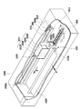
図2は、本実施形態に適用するインクジェット記録装置の要部を示す概略斜視図である。図において、インクジェット記録装置は、ケーシング1008内に長手方向に沿って設けられ、記録媒体としての用紙1028を矢印Pで示す方向に間欠的に搬送する搬送装置1030と、用紙1028の搬送方向Pに略直交する矢印S方向に略平行に、ガイド軸1014に沿って往復運動する記録部1010と、記録部1010を往復運動させる駆動手段としての移動駆動部1006とを含んで構成されている。 移動駆動部1006は、所定の間隔をもって対向配置される回転軸に配されるプーリ1026aおよび1026b、プーリ1026に巻きかけられたベルト1016、ローラユニット1022aおよび1022b、ローラユニット1022に略平行に配置され記録部1010のキャリッジ部材1010aに連結されるベルト1016を順方向及び逆方向に駆動させるモータ1018と、を含んで構成されている。
FIG. 2 is a schematic perspective view showing the main part of the ink jet recording apparatus applied to this embodiment. In the figure, an ink jet recording apparatus is provided in a
モータ1018が作動状態とされてベルト1016が矢印R方向に回転したとき、記録部1010のキャリッジ部材1010aは、矢印S方向に所定の移動量だけ移動される。また、モータ1018が作動状態とされて、ベルト1016が矢印R方向とは逆方向に回転したとき、記録部1010のキャリッジ部材1010aは、矢印S方向とは反対の方向に所定の移動量だけ移動される。更に、移動駆動部1006の一端部には、キャリッジ部材1010aのホームポジションとなる位置に、記録部1010の吐出回復処理を行うための回復ユニット1024が、記録部1010のインク吐出口配列に対向して設けられている。
When the
記録部1010は、4色のインクをそれぞれ記録するためのインクジェットカートリッジ(以下、単にカートリッジと記述する場合がある)1012Y、1012M、1012C及び1012Bによって構成されている。それぞれのカートリッジには、例えば、イエロー、マゼンタ、シアン及びブラックの顔料を含有した顔料インクが収容されており、キャリッジ部材1010aに対して着脱自在に備えられている。各カートリッジに収納されたインクは、それぞれ不図示の記録ヘッドに供給され、各記録ヘッドからは画像データに従ったインクの吐出が行われる。
The
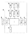
図3は、本実施形態のインクジェット記録装置における制御系の構成を説明するためのブロック図である。図において、400は、本実施形態のインクジェット記録装置であり、ホストコンピュータ2000と外部接続されている。402はCPUであり、インクジェット記録装置400内部の各種機能の制御を行っている。ホストコンピュータ2000から入力される記録すべき文字や画像のデータは、受信バッファ401を介して入力される。一方、正しくデータが受信されたか否かを通知するための信号や、記録装置400の動作状態を知らせるための信号も、受信バッファ401を介してホストコンピュータに送信される。受信バッファ401で授受されるデータは、CPU402の管理下においてメモリ部403に転送され、メモリ部403のRAMに一時的に記憶される。なお、このメモリ部403には、インクジェット記録装置で行われる記録動作や回復動作等を制御するための制御プログラムや、マルチパスの際に使用されるマスクパターンのデータが格納されている。
FIG. 3 is a block diagram for explaining a configuration of a control system in the ink jet recording apparatus of the present embodiment. In the figure,
機械コントロール部404は、CPU402からの指令により、キャリッジモータやラインフィードモータ等の機械部405の駆動制御を行う。センサ/SWコントロール部406は、各種センサやSW(スイッチ)からなるセンサ/SW部407からの信号を、CPU402に転送する。表示素子コントロール部408は、CPU402からの指令により、表示パネル群のLEDや液晶表示素子等からなる表示部409の制御を行う。記録ヘッドコントロール部410は、CPU402からの指令により、記録ヘッド104の制御を行う。また、記録ヘッドコントロール部410は、記録ヘッド104の状態を示す温度情報等を検出して、それらをCPU402に通知する。
The
図4は、本実施形態の1色分のインクジェット記録ヘッド104を示した概略斜視図である。本実施形態で適用する記録ヘッド104においては、ガラス、セラミックス、プラスチック或いは金属等からなる基板934が用いられている。このような基板の材質は、本発明の本質ではなく、流路構成部材の一部として機能し、インク吐出エネルギ発生素子、及び後述する液流路、吐出口を形成する材料層の支持体として、機能し得るものであれば特に限定されるものではない。ここでは、Si基板(ウエハ)を用いた構成で説明する。基板934上には、インク吐出口が形成されている。形成方法としては、レーザー光による形成方法の他、例えば、オリフィスプレート(吐出口プレート)935として感光性樹脂とを適用し、MPA(Mirror Projection Aliner)等の露光装置により形成する方法も挙げられる。
FIG. 4 is a schematic perspective view showing the
図において、基板934には、電気熱変換素子(以下、ヒータと記述する場合がある)931、及び、共通液室部としての長溝状の貫通口からなるインク供給口933が配備されている。ヒータ931は、インク供給口933の長手方向の両側に、それぞれ1列ずつ互いにずれた位置に配列されており、1列中では、600dpi(ドット/インチ;参考値)のピッチで各ヒータ931が配置されている。
In the figure, the
基板934には、インク流路を形成するためのインク流路壁936が設けられており、インク流路壁936には、更に各ヒータと対向した位置に配備された複数の吐出口832を備える吐出口プレート935が設けられている。
The
図においては、インク流路壁936と吐出口プレート935とは、別部材として示されているが、このインク流路壁936を、例えば、スピンコート等の手法によって基板934上に形成することにより、インク流路壁936と吐出口プレート935とを同一部材として同時に形成することも可能である。なお、吐出口面(上面)935a側は撥水処理が施されている。
In the drawing, the ink
図中示した矢印SおよびPは、図2と同様の方向を示しており、各吐出口より吐出を行いながら、矢印S方向へ記録ヘッドが移動走査する記録主走査と、記録媒体を矢印S方向へ搬送する副走査とを交互に繰り返すことにより、記録媒体である用紙1028には、1200dpiの記録密度で画像が形成される構成となっている。
The arrows S and P shown in the figure indicate the same direction as in FIG. 2. The recording main scan in which the recording head moves and scans in the arrow S direction while discharging from each discharge port, and the recording medium is indicated by the arrow S By alternately repeating the sub-scan transported in the direction, an image is formed on the
以下に、本実施形態で適用可能な顔料インクについて説明する。ここ挙げる例は、本実施形態に適用可能な例を列挙するものであって、本発明を限定するものはない。無論、背景技術の項で挙げた文献などで開示されている公知技術を利用することもできる。 Hereinafter, the pigment ink applicable in the present embodiment will be described. The examples given here list examples that can be applied to the present embodiment, and do not limit the present invention. Of course, a publicly known technique disclosed in the literature cited in the background section can also be used.
本実施形態で適用する顔料インクの顔料は、顔料インクの全重量に対して、重量比で1〜20重量%、好ましくは2〜12重量%の範囲で用いる。以下に適用可能な顔料の種類を色ごとに提示する。 The pigment of the pigment ink applied in this embodiment is used in the range of 1 to 20% by weight, preferably 2 to 12% by weight, based on the total weight of the pigment ink. The types of applicable pigments are presented below for each color.
黒色の顔料としてはカーボンブラックが挙げられ、例えば、ファーネス法、チャネル法で製造されたカーボンブラックであって、一次粒子径が15〜40mμ(nm)、BET法による比表面積が50〜300m2/g、DBP吸油量が40〜150ml/100g、揮発分が0.5〜10%、pH値が2〜9等の特性を有するものが好ましい。この様な特性を有する市販品としては、例えば、No.2300、No.900、MCF88、No.33、No.40、No.45、No.52、MA7、MA8、No.2200B(以上、三菱化成製)、RAVEN1255(以上、コロンビア製)、REGAL400R、REGAL330R、REGAL660R、MOGUL L(以上キャボット製)、Color Black FWl、COLOR Black FW18、Color Black S170、Color Black S150、Printex 35、Printex U(以上、デグッサ製)等が挙げられる。
Examples of the black pigment include carbon black. For example, carbon black produced by a furnace method or a channel method, having a primary particle diameter of 15 to 40 mμ (nm) and a specific surface area by a BET method of 50 to 300
イエローの顔料としては、例えば、C.I.Pigment Yellow 1、C.I.Pigment Yellow 2、C.I.Pigment Yellow 3、C.I.Pigment Yellow 13、C.I.Pigment Yellow 16、C.I.Pigment Yellow 83等が挙げられる。
Examples of yellow pigments include C.I. I.
マゼンタの顔料としては、例えば、C.I.Pigment Red 5、C.I.Pigment Red 7、C.I.Pigment Red 12、C.I.Pigment Red 48(Ca)、C.I.Pigment Red 48(Mn)、C.I.Pigment Red 57(Ca)、C.I.Pigment Red 112、C.I.Pigment Red 122等が挙げられる。 Examples of magenta pigments include C.I. I. Pigment Red 5, C.I. I. Pigment Red 7, C.I. I. Pigment Red 12, C.I. I. Pigment Red 48 (Ca), C.I. I. Pigment Red 48 (Mn), C.I. I. Pigment Red 57 (Ca), C.I. I. Pigment Red 112, C.I. I. Pigment Red 122 and the like.
シアンの顔料としては、例えば、C.I.Pigment Blue 1、C.I.Pigment Blue 2、C.I.Pigment Blue 3、C.I.Pigment Blue 15:3、C.I.Pigment Blue 16、C.I.Pigment Blue 22、C.I.Vat Blue 4、C.I.Vat Blue 6等が挙げられる。
Examples of cyan pigments include C.I. I.
なお、以上の他、自己分散型顔料など新たに製造された顔料も、使用することが可能である。 In addition to the above, newly produced pigments such as self-dispersing pigments can also be used.
顔料の分散剤としては、水溶性樹脂であればどの様なものでもよいが、重量平均分子量が1,000〜30,000の範囲のものが好ましく、更に好ましくは、3,000〜15,000の範囲のものが適当である。この様な分散剤として、具体的には、例えば、スチレン、スチレン誘導体、ビニルナフタレン、ビニルナフタレン誘導体、α,β−エチレン性不飽和カルボン酸の脂肪族アルコールエステル等、アクリル酸、アクリル酸誘導体、マレイン酸、マレイン酸誘導体、イタコン酸、イタコン酸誘導体、フマール酸、フマール酸誘導体、酢酸ビニル、ビニルピロリドン、アクリルアミド、及びその誘導体等から選ばれた少なくとも2つ以上の単量体(このうち少なくとも1つは親水性の重合性単量体)からなるブロック共重合体、或いは、ランダム共重合体、グラフト共重合体、又はこれらの塩等が挙げられる。或いは、ロジン、シェラック、デンプン等の天然樹脂も好ましく使用することができる。これらの樹脂は、塩基を溶解させた水溶液に可溶であり、アルカリ可溶型樹脂である。尚、これらの顔料分散剤として用いられる水溶性樹脂は、顔料インクの全重量に対して0.1〜5重量%の範囲で含有させるのが好ましいが、本発明の効果は、顔料インクの全重量に対してより少ない範囲で顕著に確認される。 The pigment dispersant may be any water-soluble resin, but preferably has a weight average molecular weight in the range of 1,000 to 30,000, more preferably 3,000 to 15,000. Those in the range of are suitable. Specifically, as such a dispersant, for example, styrene, styrene derivatives, vinyl naphthalene, vinyl naphthalene derivatives, aliphatic alcohol esters of α, β-ethylenically unsaturated carboxylic acid, acrylic acid, acrylic acid derivatives, At least two or more monomers selected from maleic acid, maleic acid derivatives, itaconic acid, itaconic acid derivatives, fumaric acid, fumaric acid derivatives, vinyl acetate, vinylpyrrolidone, acrylamide, and derivatives thereof (of which at least 1 One is a block copolymer comprising a hydrophilic polymerizable monomer), a random copolymer, a graft copolymer, or a salt thereof. Alternatively, natural resins such as rosin, shellac and starch can be preferably used. These resins are soluble in an aqueous solution in which a base is dissolved, and are alkali-soluble resins. The water-soluble resin used as the pigment dispersant is preferably contained in the range of 0.1 to 5% by weight with respect to the total weight of the pigment ink. Remarkably confirmed in a smaller range with respect to the weight.
特に、上記した様な顔料が含有されている顔料インクの場合には、顔料インクの全体が中性又はアルカリ性に調整されていることが好ましい。この様なものとすれば、顔料分散剤として使用される水溶性樹脂の溶解性を向上させ、長期保存性に一層優れた着色インクとすることができるのである。但し、この場合、インクジェット記録装置に使われている種々の部材の腐食の原因となる恐れがあるので、好ましくは、7〜10のpH範囲とするのがよい。この際に使用されるpH調整剤としては、例えば、ジエタノールアミン、トリエタノールアミン等の各種有機アミン、水酸化ナトリウム、水酸化リチウム、水酸化カリウム等のアルカリ金属の水酸化物等の無機アルカリ剤、有機酸や鉱酸等が挙げられる。上記に列挙した様な顔料及び分散剤である水溶性樹脂は、水性液媒体中に分散又は溶解される。 In particular, in the case of a pigment ink containing a pigment as described above, the entire pigment ink is preferably adjusted to be neutral or alkaline. With such a configuration, it is possible to improve the solubility of the water-soluble resin used as the pigment dispersant, and to obtain a colored ink having further excellent long-term storage stability. However, in this case, since it may cause corrosion of various members used in the ink jet recording apparatus, the pH range is preferably 7 to 10. Examples of the pH adjuster used in this case include various organic amines such as diethanolamine and triethanolamine, inorganic alkali agents such as alkali metal hydroxides such as sodium hydroxide, lithium hydroxide and potassium hydroxide, Examples include organic acids and mineral acids. The water-soluble resin, which is a pigment and a dispersant as listed above, is dispersed or dissolved in an aqueous liquid medium.
本発明で使用される顔料が含有された顔料インクにおいて好適な水性液媒体は、水及び水溶性有機溶剤の混合溶媒であり、水としては種々のイオンを含有する一般の水ではなく、イオン交換水(脱イオン水)を使用するのが好ましい。 In the pigment ink containing the pigment used in the present invention, a suitable aqueous liquid medium is a mixed solvent of water and a water-soluble organic solvent, and the water is not general water containing various ions but ion exchange. It is preferred to use water (deionized water).
水と混合して使用される水溶性有機溶剤としては、例えば、メチルアルコール、エチルアルコール、n−プロピルアルコール、イソプロピルアルコール、n−ブチルアルコール、sec−ブチルアルコール、tert−ブチルアルコール等の炭素数1〜4のアルキルアルコール類;ジメチルホルムアミド、ジメチルアセトアミド等のアミド類;アセトン、ジアセトンアルコール等のケトン又はケトアルコール類;テトラヒドロフラン、ジオキサン等のエーテル類;ポリエチレングリコール、ポリプロピレングリコール等のポリアルキレングリコール類;エチレングリコール、プロピレングリコール、ブチレングリコール、トリエチレングリコール、1,2,6−ヘキサントリオール、チオジグリコール、ヘキシレングリコール、ジエチレングリコール等のアルキレン基が2〜6個の炭素原子を含むアルキレングリコール類;グリセリン;エチレングリコールモノメチル(又はエチル)エーテル、ジエチレングリコールメチル(又はエチル)エーテル、トリエチレングリコールモノメチル(又はエチル)エーテル等の多価アルコールの低級アルキルエーテル類;N−メチル−2−ピロリドン、2−ピロリドン、1,3−ジメチル−2−イミダゾリジノン等が挙げられる。これらの多くの水溶性有機溶剤の中でも、ジエチレングリコール等の多価アルコール、トリエチレングリコールモノメチル(又はエチル)エーテル等の多価アルコールの低級アルキルエーテルが好ましい。 Examples of the water-soluble organic solvent used by mixing with water include carbon atoms of 1 such as methyl alcohol, ethyl alcohol, n-propyl alcohol, isopropyl alcohol, n-butyl alcohol, sec-butyl alcohol, tert-butyl alcohol, and the like. Alkyl alcohols of -4; amides such as dimethylformamide and dimethylacetamide; ketones or ketoalcohols such as acetone and diacetone alcohol; ethers such as tetrahydrofuran and dioxane; polyalkylene glycols such as polyethylene glycol and polypropylene glycol; Ethylene glycol, propylene glycol, butylene glycol, triethylene glycol, 1,2,6-hexanetriol, thiodiglycol, hexylene glycol, diethylene glycol Alkylene glycols having 2 to 6 carbon atoms, such as coal; glycerin; ethylene glycol monomethyl (or ethyl) ether, diethylene glycol methyl (or ethyl) ether, triethylene glycol monomethyl (or ethyl) ether, etc. Lower alkyl ethers of monohydric alcohols; N-methyl-2-pyrrolidone, 2-pyrrolidone, 1,3-dimethyl-2-imidazolidinone and the like. Among these many water-soluble organic solvents, polyhydric alcohols such as diethylene glycol and lower alkyl ethers of polyhydric alcohols such as triethylene glycol monomethyl (or ethyl) ether are preferred.
上記した様な水溶性有機溶剤の顔料インク中の含有量は、一般的には、顔料インクの全重量の3〜50重量%の範囲、より好ましくは3〜40重量%の範囲で使用する。又、使用される水の含有量としては、顔料インクの全重量の10〜90重量%、好ましくは30〜80重量%の範囲とする。 The content of the water-soluble organic solvent as described above in the pigment ink is generally 3 to 50% by weight, more preferably 3 to 40% by weight, based on the total weight of the pigment ink. The water content used is in the range of 10 to 90% by weight, preferably 30 to 80% by weight, based on the total weight of the pigment ink.
又、本発明および本実施形態に適用可能な顔料インクとしては、上記の成分の他に、必要に応じて所望の物性値を持つ着色インクとする為に、界面活性剤、消泡剤、防腐剤等を適宜に添加することができる。特に浸透促進剤として機能する界面活性剤は、記録媒体に顔料インクの液体成分を速やかに浸透させる役割を担うための適量を添加する必要がある。添加量の例としては、0.05〜10重量%、好ましくは0.5〜5重量%が好適である。アニオン性界面活性剤の例としては、カルボン酸塩型、硫酸エステル型、スルホン酸塩型、燐酸エステル型等、一般に使用されているものを何れも好ましく使用することができる。 In addition to the above components, the pigment ink applicable to the present invention and the present embodiment includes a surfactant, an antifoaming agent, an antiseptic, in order to obtain a colored ink having desired physical properties as required. An agent or the like can be appropriately added. In particular, the surfactant functioning as a penetration accelerator needs to be added in an appropriate amount to play a role of promptly penetrating the liquid component of the pigment ink into the recording medium. As an example of the addition amount, 0.05 to 10% by weight, preferably 0.5 to 5% by weight is suitable. As examples of the anionic surfactant, any commonly used ones such as a carboxylate type, a sulfate type, a sulfonate type, and a phosphate type can be preferably used.
上記した顔料インクの作製方法を説明する。始めに、分散剤としての水溶性樹脂と、水とが少なくとも含有された水性媒体に顔料を添加し、混合撹拌した後、後述の分散手段を用いて分散を行い、必要に応じて遠心分離処理を行って所望の分散液を得る。次に、この分散液にサイズ剤、及び、上記で挙げた様な適宜に選択された添加剤成分を加え撹拌して顔料インクとする。 A method for producing the above-described pigment ink will be described. First, a pigment is added to an aqueous medium containing at least a water-soluble resin as a dispersant and water, and after mixing and stirring, dispersion is performed using a dispersion means described later, and centrifugation is performed as necessary. To obtain the desired dispersion. Next, a sizing agent and appropriately selected additive components such as those mentioned above are added to this dispersion and stirred to obtain a pigment ink.
なお、分散剤として前記した様なアルカリ可溶型樹脂を使用する場合には、樹脂を溶解させる為に塩基を添加することが必要であるが、この際の塩基類としては、モノエタノールアミン、ジエタノールアミン、トリエタノールアミン、アミンメチルプロパノール、アンモニア等の有機アミン、或いは水酸化カリウム、水酸化ナトリウム等の無機塩基が好ましく使用される。 In addition, when using an alkali-soluble resin as described above as a dispersant, it is necessary to add a base in order to dissolve the resin. Examples of the base at this time include monoethanolamine, Organic bases such as diethanolamine, triethanolamine, amine methyl propanol and ammonia, or inorganic bases such as potassium hydroxide and sodium hydroxide are preferably used.
また、顔料インクの作製方法においては、顔料を含む水性媒体を攪拌し、分散処理する前に、プレミキシングを30分間以上行うのが効果的である。即ち、この様なプレミキシング操作は、顔料表面の濡れ性を改善し、顔料表面への分散剤の吸着を促進することができる為、好ましい。 In addition, in the method for producing the pigment ink, it is effective to perform premixing for 30 minutes or more before stirring and dispersing the aqueous medium containing the pigment. That is, such a premixing operation is preferable because it improves wettability of the pigment surface and promotes adsorption of the dispersant onto the pigment surface.
上記した顔料の分散処理の際に使用される分散機は、一般に使用される分散機なら、如何なるものでもよいが、例えば、ボールミル、ロールミル及びサンドミル等が挙げられる。その中でも、高速型のサンドミルが好ましく使用される。この様なものとしては、例えば、スーパーミル、サンドグラインダー、ビーズミル、アジテータミル、グレンミル、ダイノーミル、パールミル及びコボルミル(何れも商品名)等が挙げられる。 The disperser used in the above-described pigment dispersion treatment may be any disperser that is generally used, and examples thereof include a ball mill, a roll mill, and a sand mill. Among these, a high speed type sand mill is preferably used. Examples of such a material include a super mill, a sand grinder, a bead mill, an agitator mill, a glen mill, a dyno mill, a pearl mill, and a cobol mill (all are trade names).
また、顔料インクをインクジェット記録方法では、記録素子での目詰りを防止するために、最適な粒度分布を有する顔料を用いるが、所望の粒度分布を有する顔料を得る方法としては、分散機の粉砕メディアのサイズを小さくすること、粉砕メディアの充填率を大きくすること、処理時間を長くすること、吐出速度を遅くすること、粉砕後フィルタや遠心分離機等で分級すること、及びこれらの手法の組合せ等の手法が挙げられる。 In addition, in the ink jet recording method for pigment ink, a pigment having an optimum particle size distribution is used in order to prevent clogging in the recording element. As a method for obtaining a pigment having a desired particle size distribution, pulverization by a disperser is used. Reducing the size of the media, increasing the filling rate of the grinding media, increasing the processing time, slowing the discharge speed, classifying with a filter or centrifuge after grinding, and Examples of the method include a combination.
以下に、本実施形態のインクジェット記録装置における記録方法を説明する。本実施形態のインクジェット記録装置は、普通紙のほか、上質紙として表面に光沢を有する光沢紙、光沢を有さないマット紙などへの記録が可能となっている。どの記録媒体に対しても上述したマルチパス記録を適用するが、記録媒体の種類によってマルチパス数および適用するマスクの形態を異ならせている。図3で示したメモリ403には、各記録媒体に対応するマスクパターンが予め複数格納されているものとする。
Below, the recording method in the inkjet recording device of this embodiment is demonstrated. In addition to plain paper, the ink jet recording apparatus according to the present embodiment can perform recording on glossy paper having a gloss on the surface or matte paper having no gloss as a high-quality paper. The multi-pass recording described above is applied to any recording medium, but the number of multi-passes and the form of the mask to be applied differ depending on the type of the recording medium. In the
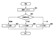
図5は、本実施形態のCPU402が行う、記録時の判断処理および記録処理を説明するためのフローチャートである。記録が開始されると、ステップS51にて、CPU402は、まずホストコンピュータ2000より画像データを受信する。画像データには、実際の画像データのほか、記録媒体の種類などの情報が含まれている。
FIG. 5 is a flowchart for explaining recording determination processing and recording processing performed by the
ステップS52では、受信した画像データの情報を解析し、これから記録する記録媒体の種類が普通紙であるか、光沢紙であるか、マット紙であるかを判断する。普通紙と判断された場合ステップS53に進み、2パスのマルチパス記録によって画像が形成される。光沢紙と判断された場合、S54へ進み、4パスのマルチパス記録によって画像が形成される。また、マット紙である場合には、ステップS55へ進み、やはり4パスのマルチパス記録によって画像が形成される。 In step S52, the information of the received image data is analyzed, and it is determined whether the type of recording medium to be recorded is plain paper, glossy paper, or matte paper. If it is determined to be plain paper, the process proceeds to step S53, and an image is formed by two-pass multi-pass printing. If it is determined that the paper is glossy, the process proceeds to S54, and an image is formed by 4-pass multi-pass printing. If it is mat paper, the process proceeds to step S55, where an image is formed by 4-pass multi-pass printing.
図6(a)〜(c)は、ステップS53〜S55のそれぞれで適用されるマスクパターンを示した図である。各格子は1つのインクドットが記録される領域(1画素)を示しており、ここでは、16画素×16画素の領域におけるマスクパターンを示している。実際の記録の際には、ここに示す16画素×16画素のマスクパターンが、縦横ともに繰り返されて適用されるものと考えてよい。 FIGS. 6A to 6C are diagrams showing mask patterns applied in steps S53 to S55, respectively. Each grid indicates an area (one pixel) in which one ink dot is recorded. Here, a mask pattern in an area of 16 pixels × 16 pixels is illustrated. In actual recording, it may be considered that the mask pattern of 16 pixels × 16 pixels shown here is repeatedly applied both vertically and horizontally.
図6(a)は、ステップS53において、普通紙に適用される2パスのマスクパターンを示している。記録媒体においては、まず第1の記録走査にて、1パス目のマスクパターンに従って間引かれた記録データが記録される。続く第2の記録走査では2パス目のマスクパターンに従って間引かれた記録データが記録される。1パス目と2パス目のマスクパターンは、互いに補完の関係にあるため、記録媒体の同一画像領域においては、以上2回の記録走査で画像データの全てが記録される。 FIG. 6A shows a two-pass mask pattern applied to plain paper in step S53. In the recording medium, firstly, the recording data thinned out in accordance with the first pass mask pattern is recorded in the first recording scan. In the subsequent second recording scan, the recording data thinned out according to the second pass mask pattern is recorded. Since the first-pass and second-pass mask patterns are complementary to each other, all the image data is recorded in the same image area of the recording medium by the above-described two recording scans.
図6(b)は、ステップS54において、光沢紙に適用される4パスのマスクパターンを示している。記録媒体においては、普通紙と同様に、まず第1の記録走査にて、1パス目のマスクパターンに従って間引かれた記録データが記録され、続く第2、第3、および第4の記録走査で、それぞれのマスクパターンに従って間引かれた記録データが記録される。1パス目〜4パス目のマスクパターンは、互いに補完の関係にあるため、記録媒体の同一画像領域においては、4回の記録走査で画像データの全てが記録される。 FIG. 6B shows a 4-pass mask pattern applied to glossy paper in step S54. In the recording medium, as in the case of plain paper, first, the recording data thinned out in accordance with the mask pattern of the first pass is recorded in the first recording scan, and then the second, third, and fourth recording scans are performed. Thus, the thinned recording data is recorded according to the respective mask patterns. Since the first to fourth pass mask patterns are complementary to each other, all of the image data is recorded in four recording scans in the same image area of the recording medium.
図6(c)は、ステップS55において、マット紙に適用される4パスのマスクパターンを示している。記録媒体においては、光沢紙と同様に、まず第1の記録走査にて、1パス目のマスクパターンに従って間引かれた記録データが記録され、続く第2、第3、および第4の記録走査で、それぞれのマスクパターンに従って間引かれた記録データが記録される。1パス目〜4パス目のマスクパターンは、互いに補完の関係にあるため、記録媒体の同一画像領域においては、4回の記録走査で画像データの全てが記録される。 FIG. 6C shows a 4-pass mask pattern applied to the matte paper in step S55. In the recording medium, like glossy paper, first, the recording data thinned out in accordance with the mask pattern of the first pass is recorded in the first recording scan, and the subsequent second, third, and fourth recording scans are performed. Thus, the thinned recording data is recorded according to the respective mask patterns. Since the first to fourth pass mask patterns are complementary to each other, all of the image data is recorded in four recording scans in the same image area of the recording medium.
ステップS54およびステップS55では、ともに4パスのマルチパス記録が行われるが、それぞれ適用されるマスクパターンが異なっている。図6(b)では、4画素×4画素が同じ走査で記録される単位領域を形成しており、この領域を単位として各記録走査でインクが付与されている。これに対して、図6(c)では、隣接した画素は同じ記録走査では記録されない構成となっており、記録媒体においては単独ドットが分散されて付与される形態となっている。 In steps S54 and S55, 4-pass multi-pass printing is performed, but the mask patterns to be applied are different. In FIG. 6B, a unit area in which 4 pixels × 4 pixels are recorded by the same scan is formed, and ink is applied in each recording scan using this area as a unit. On the other hand, in FIG. 6C, the adjacent pixels are not recorded by the same recording scan, and the single dots are distributed and applied on the recording medium.
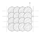
図7は、上記図6(b)のマスクを用いて記録媒体にインクを付与した場合の、ドットの記録状態を示した図である。ここに示される16ドットは、図1(d)と同様に広がって記録されているが、全て1回目の記録走査で記録されたドット1となっており、記録媒体上での堆積状態は一様となっている。
FIG. 7 is a diagram showing a dot recording state when ink is applied to the recording medium using the mask of FIG. 6B. The 16 dots shown here are spread and recorded in the same manner as in FIG. 1D, but all are
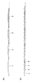
図8は、上記図6(b)および(c)のマスクを用いて記録媒体にインクを付与した場合の、記録媒体上でインクが堆積する状態を示した模式的断面図である。図8(a)は、図6(b)のマスクに従って4パスのマルチパス記録を行った場合のインクの堆積状態、図8(b)は、図6(c)のマスクに従って、4パスのマルチパス記録を行った場合のインクの堆積状態をそれぞれ示している。1パス目の記録走査で記録されたドット〜4パス目の記録走査で記録されたドットは、図1と同様に1〜4として示している。先行する記録走査で付与されたインクは記録媒体上で堆積しながらも、より下層に定着している。図からも判るように、適用するマスクパターンによって、記録媒体表面の平滑性に差が現れていることが分かる。 FIG. 8 is a schematic cross-sectional view showing a state in which ink is deposited on the recording medium when ink is applied to the recording medium using the masks of FIGS. 6B and 6C. FIG. 8A shows the state of ink accumulation when 4-pass multi-pass printing is performed according to the mask of FIG. 6B, and FIG. 8B shows the 4-pass print according to the mask of FIG. 6C. The ink accumulation states when multi-pass printing is performed are shown. The dots recorded in the first pass printing scan to the dots printed in the fourth pass printing scan are shown as 1 to 4 as in FIG. The ink applied in the preceding recording scan is fixed on the lower layer while being deposited on the recording medium. As can be seen from the figure, it can be seen that there is a difference in the smoothness of the surface of the recording medium depending on the mask pattern to be applied.
マット紙の場合、特に記録部の光沢感に関する問題は提起されないので、平滑性を保つための記録方法を特別駆使する必要はない。よって、本実施形態においては従来と同様に分散性に富んだマスクパターンを適用している。一方、光沢紙の場合、顔料インクを適用した場合には、記録部と非記録部の光沢感の差異が問題となる。よって、本実施形態においては、図6(b)に示したようなマスクパターンを適用することによって、記録媒体表面での平滑性を極力維持することに努めている。 In the case of matte paper, there is no particular problem with the glossiness of the recording portion, so there is no need to make full use of a recording method for maintaining smoothness. Therefore, in the present embodiment, a mask pattern with high dispersibility is applied as in the prior art. On the other hand, in the case of glossy paper, when pigment ink is applied, a difference in glossiness between the recording portion and the non-recording portion becomes a problem. Therefore, in the present embodiment, an effort is made to maintain the smoothness on the surface of the recording medium as much as possible by applying a mask pattern as shown in FIG.
なお、ここでは、4画素×4画素を単位領域としたマスクパターンを用いて説明してきたが、本実施形態の効果を得るための形態は、これに限ったものではない。記録媒体表面の凹凸は、異なる記録走査で記録される2つのドットの重なり部において発生するものである。本実施形態のように4画素×4画素を1度に記録することは、上記重なり部自体をなるべく発生させないという作用があり、これによって凹凸が減り平滑性が保たれているのである。よって、4画素×4画素でなくとも、n×m画素の単位、あるいは矩形でなくとも複数の画素が集中して記録される構成とすれば、本実施形態の効果は得られるのである。但し、単位領域内ではマルチパス記録の効果は得られないので、あまり大きな領域に設定すると、画像弊害が確認される恐れもある。単位領域の大きさや形状は、光沢の度合いと、マルチパス記録の効果とのバランスを保ちながら、状況に応じて好適に設定されればよい。 Here, the description has been given using the mask pattern having 4 pixels × 4 pixels as a unit region, but the form for obtaining the effect of the present embodiment is not limited to this. Irregularities on the surface of the recording medium occur at the overlapping portion of two dots recorded by different recording scans. Recording 4 pixels × 4 pixels at a time as in this embodiment has the effect of preventing the overlapping portion itself from being generated as much as possible, thereby reducing unevenness and maintaining smoothness. Therefore, the effect of the present embodiment can be obtained by using a configuration in which a plurality of pixels are concentrated and recorded in units of n × m pixels, or not rectangular, even if the pixels are not 4 pixels × 4 pixels. However, since the effect of multi-pass printing cannot be obtained in the unit area, if the area is set to be too large, there is a risk that image defects will be confirmed. The size and shape of the unit area may be suitably set according to the situation while maintaining a balance between the degree of gloss and the effect of multipass printing.
無論、マルチパス数も4パスに限ったものではない。より少ないパス数でも、またより多いパス数であっても、複数の画素が集中して構成される画素群を単位としたマルチパス記録であれば、本実施形態の効果を得ることは出来る。 Of course, the number of multipaths is not limited to four. Even with a smaller number of passes or a larger number of passes, the effect of the present embodiment can be obtained as long as multi-pass printing is performed in units of pixel groups formed by concentrating a plurality of pixels.
この様に、複数の画素が集中して構成される画素群を単位として記録・非記録を決定した形態のマスクパターン自体は、既に従来から様々な目的で適用されている。しかし、以上説明した本実施形態のように、光沢感を重視する記録媒体が選択された場合に、その表面の平滑性を維持することを目的として、上述したようなマスクパターンが複数の中から適用されるような構成は、未だ存在していなかった。 As described above, the mask pattern itself in which recording / non-recording is determined in units of a pixel group formed by concentrating a plurality of pixels has already been applied for various purposes. However, as in the present embodiment described above, when a recording medium that emphasizes glossiness is selected, the mask pattern as described above is selected from a plurality of masks for the purpose of maintaining the smoothness of the surface. There was still no configuration to apply.
以上説明したように、本実施形態によれば、光沢紙が記録される場合には、複数の画素が集中して構成される画素群を単位としたマスクパターンを適用することにより、記録部の光沢感を非記録部に対して極力損なわずに画像を形成することが可能となった。 As described above, according to the present embodiment, when glossy paper is recorded, by applying a mask pattern based on a pixel group in which a plurality of pixels are concentrated, An image can be formed without losing the gloss feeling as much as possible to the non-recording portion.
(第2の実施形態)
以下に本発明の第2の実施形態を説明する。本実施形態においても第1の実施形態と同様に、図2および図3で説明したインクジェット記録装置を適用するものとする。但し、本実施形態においては、光沢紙に記録を行う際には、マルチパス記録を行わずに、1パス記録を実施する構成とする。
(Second Embodiment)
The second embodiment of the present invention will be described below. In the present embodiment, the ink jet recording apparatus described with reference to FIGS. 2 and 3 is applied as in the first embodiment. However, in the present embodiment, when recording is performed on glossy paper, one-pass recording is performed without performing multi-pass recording.
すでに説明したように、マルチパス記録には、様々なノイズを分散させる効果や、吸収速度が遅いインクや記録媒体の場合にも良好な画像を得られるという効果がある。しかしながら、記録速度を遅くしてしまうと言う欠点もある。 As already described, multipass printing has an effect of dispersing various noises and an effect of obtaining a good image even in the case of an ink or a recording medium having a slow absorption speed. However, there is a drawback that the recording speed is slowed down.
一方、光沢紙のような特殊な記録媒体においては、吸収速度を速めるための工夫や改善が施されてきており、近年では、顔料インクを適用した場合でも、定着時間に関する問題は殆ど解決されている。また、記録素子の製造ばらつきや、記録媒体の搬送ばらつきについても、明確な改善効果が現れており、マルチパス記録が発揮する効果も、従来に比べて少なくなって来ている。 On the other hand, special recording media such as glossy paper have been devised and improved to increase the absorption speed. In recent years, even when pigment ink is applied, the problems related to fixing time are almost solved. Yes. In addition, there is a clear improvement effect with respect to the manufacturing variation of the recording element and the conveyance variation of the recording medium, and the effect of multi-pass recording is reduced compared to the conventional case.
このような状況において、マルチパスを採用した際の光沢感の劣化は顕著に目立ち、マルチパス記録を採用された場合の効果よりも、弊害のほうが大きく認識される場合も少なくない。 In such a situation, the deterioration of glossiness when the multi-pass is adopted is conspicuous, and the harmful effect is often recognized more than the effect when the multi-pass recording is adopted.
よって、本実施形態においては、光沢紙が選択された場合には、マルチパスを採用せずに、1パス記録を行うものとする。1パス記録であれば、上述したマスクパターンを適用せずとも、全ての画像データが同じ走査で記録されるので、記録媒体に付与されたインクも一様に堆積し、記録表面での平滑性を保つことが出来る。 Therefore, in this embodiment, when glossy paper is selected, one-pass printing is performed without using multi-pass. In the case of one-pass printing, all image data is recorded by the same scanning without applying the above-described mask pattern, so that the ink applied to the recording medium is uniformly deposited and smoothness on the recording surface is achieved. Can be kept.
以下に、本実施形態の効果を確認するために、実際に発明者らが行った検討内容およびその結果を報告する。尚、以下の記載において、部、%とあるものは特に断わらない限り重量基準である。 In the following, in order to confirm the effect of the present embodiment, the contents of examination and the results actually conducted by the inventors are reported. In the following description, “part” and “%” are based on weight unless otherwise specified.
まず下記に述べる様にして、夫々顔料とアニオン性化合物とを含むブラックの顔料インクを得た。 First, as described below, black pigment inks each containing a pigment and an anionic compound were obtained.
(顔料インクK1)
−顔料分散液の作製
スチレン-アクリル酸-アクリル酸エチル共重合体 (酸価240、重量平均分子量=5000) 1.5部
モノエタノールアミン 1.0部
ジエチレングリコール 5.0部
イオン交換水 81.5部
上記成分を混合し、ウォーターバスで70℃に加温し、樹脂分を完全に溶解させる。この溶液に新たに試作されたカーボンブラック(MCF88、三菱化成製)10部、イソプロピルアルコール1部を加え、30分間プレミキシングを行った後、下記の条件で分散処理を行った。
(Pigment ink K1)
-Preparation of pigment dispersion Styrene-acrylic acid-ethyl acrylate copolymer (acid value 240, weight average molecular weight = 5000) 1.5 parts monoethanolamine 1.0 part diethylene glycol 5.0 parts ion-exchanged water 81.5 Part The above components are mixed and heated to 70 ° C. in a water bath to completely dissolve the resin component. To this solution, 10 parts of newly produced carbon black (MCF88, manufactured by Mitsubishi Kasei) and 1 part of isopropyl alcohol were added, premixed for 30 minutes, and then dispersed under the following conditions.
分散機:サンドグラインダー(五十嵐機械製)
粉砕メディア:ジルコニウムビーズ、1mm径
粉砕メディアの充填率:50%(体積比)
粉砕時間:3時間
更に、遠心分離処理(12,000rpm.、20分間)を行い、粗大粒子を除去して顔料分散液とした。
Dispersing machine: Sand grinder (Igarashi Machine)
Grinding media: Zirconium beads, 1 mm diameter Filling rate of grinding media: 50% (volume ratio)
Grinding time: 3 hours Further, a centrifugal separation process (12,000 rpm, 20 minutes) was performed to remove coarse particles to obtain a pigment dispersion.
−顔料インクK1の作製
上記の分散液を使用し、下記の組成比を有する成分を混合し、顔料を含有するインクを作製して顔料インクとした。
—Preparation of Pigment Ink K1 Using the above dispersion, components having the following composition ratios were mixed to prepare an ink containing a pigment to obtain a pigment ink.
上記顔料分散液 30.0部
グリセリン 10.0部
エチレングリコール 5.0部
N−メチルピロリドン 5.0部
エチルアルコール 2.0部
アセチレノールEH(川研ファインケミカル製) 1.0部
イオン交換水 47.0部
Pigment dispersion 30.0 parts Glycerin 10.0 parts Ethylene glycol 5.0 parts N-methylpyrrolidone 5.0 parts Ethyl alcohol 2.0 parts Acetylenol EH (manufactured by Kawaken Fine Chemicals) 1.0 part Ion-exchanged water 47. 0 copies
次にインクジェット記録装置(PIXUS−850i/キヤノン製)で適用されているカラー用のインクタンクに顔料インクK1を充填し、上記インクジェット記録装置PIXUS−850iで適用する記録ヘッドに装着した。 Next, the pigment ink K1 was filled in the color ink tank applied in the ink jet recording apparatus (PIXUS-850i / manufactured by Canon) and mounted on the recording head applied in the ink jet recording apparatus PIXUS-850i.
記録媒体は、光沢を有しつつも、高画質な画像を実現可能なものとして、プロフェッショナルフォトペーパー(PR−101/キヤノン製)を適用した。記録する画像は、全画素に1ドットずつブラックのインク滴が付与される、いわゆるブラックのベタ画像とし、縦2cm、横2cmのパッチとした。 As the recording medium, professional photo paper (PR-101 / manufactured by Canon) was applied as a recording medium capable of realizing a high-quality image while having gloss. The image to be recorded was a so-called black solid image in which black ink droplets were applied to each pixel one dot at a time, and a patch of 2 cm in length and 2 cm in width.
記録方法は以下の4種類の記録方法にて行った。1つ目はマルチパス記録を採用しない1パス記録、2つ目は図6(a)で示したマスクを採用した2パス記録、3つ目は図6(c)で示したマスクを採用した4パス記録、4つ目は図6(c)のそれぞれを更に分割して得られる8種類のマスクを用いて行った8パス記録である。 The recording method was the following four types of recording methods. The first is one-pass printing that does not employ multi-pass printing, the second is two-pass printing that uses the mask shown in FIG. 6A, and the third is the mask shown in FIG. 6C. 4-pass printing, and the fourth is 8-pass printing performed using eight types of masks obtained by further dividing each of FIG.
それぞれの方法で記録されたパッチに対し、光沢度を測定した。光沢度計は、IG−330(堀場製作所製)を用い、20度モードで測定を行った。結果、1パス記録における光沢度は138、2パス記録における光沢度は97、4パス記録における光沢度は63、8パス記録における光沢度は50となった。すなわち、このように適用するマスクパターンやマルチパスの回数を調整することによって、記録媒体表面の平滑度よび光沢性を制御することが出来るのである。 Glossiness was measured for patches recorded by each method. The gloss meter used IG-330 (manufactured by HORIBA, Ltd.) and measured in a 20 degree mode. As a result, the glossiness in the 1-pass printing was 138, the glossiness in the 2-pass printing was 97, the glossiness in the 4-pass printing was 63, and the glossiness in the 8-pass printing was 50. That is, the smoothness and glossiness of the surface of the recording medium can be controlled by adjusting the mask pattern and the number of multi-passes applied in this way.
上記結果からも、本実施形態のように、光沢紙に記録を行う際にはマルチパス記録を行わずに、1パス記録を実施する構成とすることにより、記録部の光沢感を非記録部に対して極力損なわずに画像を形成することが可能となった。 From the above results, it can be seen that the glossiness of the recording unit is reduced to the non-recording unit by performing the one-pass recording without performing multi-pass recording when recording on glossy paper as in the present embodiment. As a result, it is possible to form an image without losing as much as possible.
(第3の実施形態)
以下に本発明の第3の実施形態を説明する。上記第2の実施形態では、光沢紙に対して常に1パス記録を行う構成としたが、全ての光沢紙において、1パス記録で得られる平滑性が適切であるとは限らない。別の記録方法のほうが光沢に関してより違和感がない場合もある。本実施形態では、以上の状況を踏まえ、記録媒体の種類に応じた記録方法を記録装置が自動で判断および制御する構成とする。
(Third embodiment)
The third embodiment of the present invention will be described below. In the second embodiment, the one-pass printing is always performed on the glossy paper. However, the smoothness obtained by the one-pass printing is not always appropriate for all glossy papers. In some cases, another recording method is less uncomfortable with respect to gloss. In the present embodiment, based on the above situation, the recording apparatus automatically determines and controls the recording method according to the type of the recording medium.
本実施形態でも上記実施形態と同様のインクジェット記録装置を適用するものとする。ただし、本実施形態においては、記録媒体を給紙するための給紙部に、光沢センサとして光沢度計測回路(フォトリフレクタKR640(新光電子製))を給紙部に取り付けた。図3のブロック図においては、センサ/SW部407にこの光沢センサが含まれる構成となる。光沢センサは、給紙動作が行われるたびに、記録媒体の光沢度を計測し、その情報をCPU402に転送する。CPU402は、得られた情報から適切な記録方法およびマスクパターンを選択し、記録を実行する。
In this embodiment, the same ink jet recording apparatus as that in the above embodiment is applied. However, in the present embodiment, a glossiness measurement circuit (photo reflector KR640 (manufactured by Shinko Denshi)) is attached to the paper feed unit as a gloss sensor in the paper feed unit for feeding the recording medium. In the block diagram of FIG. 3, the sensor /
例えば、上述した第2の実施形態での検討でも、プロフェッショナルフォトペーパー(PR−101)においては、2パスのマルチパス記録を行った場合の光沢が、最も適切であったとする。この場合、プロフェッショナルフォトペーパー(PR−101)が給紙された時点で、上記センサがこの光沢度を感知し、CPU402に結果を転送する。CPU402は、得られた結果より、2パス用のマスクをメモリ403から読み出し、2パスのマルチパス記録により記録を実行する。これにより、プロフェッショナルフォトペーパーにおいて、記録部と非記録部とで光沢感に殆ど差異がなくなり、違和感のない出力物を得ることが出来る。他の記録媒体についても、同様の工程に従って記録方法が選択され、適切な光沢が得られる方法で画像が形成される。
For example, even in the examination in the second embodiment described above, in professional photo paper (PR-101), it is assumed that the gloss when 2-pass multi-pass printing is performed is most appropriate. In this case, when the professional photo paper (PR-101) is fed, the sensor detects the glossiness and transfers the result to the
以上説明したように、本実施形態によれば、記録媒体の非記録部における光沢度を予め測定する手段を設け、測定結果より適切なマスクパターンとマルチパス数を選択可能な構成とすることにより、互いに異なる光沢度を有する複数の記録媒体に対しても、光沢感において、違和感のない出力物を安定して得ることが出来る。 As described above, according to this embodiment, by providing means for measuring the glossiness in the non-recording portion of the recording medium in advance, it is possible to select an appropriate mask pattern and multipass number from the measurement result. Even for a plurality of recording media having different glossinesses, it is possible to stably obtain an output product that does not feel uncomfortable in terms of glossiness.
なお、本実施形態においては、光沢センサとしてフォトリフレクタKR640(新光電子製)を採用したが、これは特に規定されるものではない。一般的な光学的手法を用いたものであれば、どの様なものを使用することができる。フォトリフレクタKR640のほか、例えば、KR641、KR650、KR651(いずれも新光電子製)などを用いることもできる。また、個々に発光ダイオードとフォトダイオードなどを組み合わせることもできる。 In the present embodiment, the photo reflector KR640 (manufactured by Shinko Denshi) is used as the gloss sensor, but this is not particularly specified. Any device that uses a general optical technique can be used. In addition to the photoreflector KR640, for example, KR641, KR650, KR651 (all manufactured by Shinko Electronics Co., Ltd.) can be used. In addition, a light emitting diode and a photodiode can be combined individually.
なお、記録部と非記録部における光沢感については、センサによる測定値と実際に目視で判断した場合とで異なる場合もある。このような場合には、予めインクジェット記録装置に測定結果に対して補正手段を有しても構わない。 Note that glossiness in the recording portion and the non-recording portion may differ depending on the value measured by the sensor and the case where it is actually determined visually. In such a case, the inkjet recording apparatus may have a correction unit for the measurement result in advance.
以上3つの実施形態では、記録部と非記録部とで極力同様の光沢感が得られるように記録方法を制御したが、あえて記録部の光沢感を非記録部と異ならせるように制御することも出来る。光沢感に対する要求が、ユーザの好みや使用目的に応じて様々である場合には、ユーザが状況に応じて、光沢度のレベルを設定可能な構成としても良い。いずれにせよ、記録媒体の表面における光沢度を記録方法によって制御可能な構成とすれば、本発明は有効なのである。 In the above three embodiments, the recording method is controlled so that the recording section and the non-recording section can obtain the same glossiness as much as possible, but the recording section is controlled so that the glossiness of the recording section is different from that of the non-recording section. You can also. When there are various demands for glossiness according to the user's preference and purpose of use, the user may set the gloss level according to the situation. In any case, the present invention is effective if the glossiness on the surface of the recording medium can be controlled by the recording method.
以上の実施形態で採用する記録ヘッドにおいては、図4で説明したように、熱エネルギを利用して飛翔的液滴を形成し、記録を行う構成を採用した。この代表的な構成や原理については、例えば、特許文献7及び特許文献8に開示されている基本的な原理を用いて行うものが好ましい。 In the recording head employed in the above embodiment, as described with reference to FIG. 4, a configuration is adopted in which flying droplets are formed using thermal energy and recording is performed. About this typical structure and principle, what is performed using the basic principle currently disclosed by patent document 7 and patent document 8, for example is preferable.
この方式は、いわゆるオンデマンド型及びコンティニュアス型のいずれにも適用可能であるが、特に、オンデマンド型の場合には、液体(インク)が保持されているシートや液路に対応して配置されている電気熱変換体に、記録情報に対応していて膜沸騰を超える急速な温度上昇を与える少なくとも一つの駆動信号を印加することによって、電気熱変換体に熱エネルギを発生せしめ、記録ヘッドの熱作用面に膜沸騰を生じさせて、結果的に、この駆動信号に一対一で対応した液体(インク)内の気泡を形成できるので有効である。この気泡の成長及び収縮により吐出用開口を介して液体(インク)を吐出させて、少なくとも一つの液滴を形成する。この駆動信号をパルス形状とすると、即時適切に気泡の成長収縮が行なわれるので、特に応答性に優れた液体(インク)の吐出が達成でき、より好ましい。 This method can be applied to both a so-called on-demand type and a continuous type. In particular, in the case of the on-demand type, it corresponds to a sheet or a liquid path that holds liquid (ink). By applying at least one drive signal that corresponds to the recorded information and gives a rapid temperature rise exceeding film boiling to the arranged electrothermal transducer, thermal energy is generated in the electrothermal transducer, and recording is performed. This is effective because film boiling occurs on the heat acting surface of the head, and as a result, bubbles in the liquid (ink) corresponding to the drive signal on a one-to-one basis can be formed. By the growth and contraction of the bubbles, liquid (ink) is ejected through the ejection opening to form at least one droplet. It is more preferable that the drive signal has a pulse shape, since the bubble growth and contraction is performed immediately and appropriately, and thus it is possible to achieve discharge of liquid (ink) having particularly excellent responsiveness.
この際のパルス形状の駆動信号としては、特許文献9及び特許文献10に記載されているようなものが適している。尚、上記熱作用面の温度上昇率についての発明に関する特許文献11に記載されている条件を採用すると、更に、優れた記録を行なうことができる。 As the pulse-shaped drive signal at this time, those described in Patent Document 9 and Patent Document 10 are suitable. In addition, if the conditions described in Patent Document 11 relating to the invention concerning the temperature rise rate of the heat acting surface are employed, further excellent recording can be performed.
本発明に適用可能な記録ヘッドの構成としては、上記に挙げた各明細書に開示されているような吐出口、液路及び電気熱変換体の組み合わせ構成(直線状液流路又は直角液流路)の他に、熱作用部が屈曲する領域に配置されている構成を開示する特許文献12及び特許文献13を用いた構成のものを使用することも好ましい。 As a configuration of the recording head applicable to the present invention, a combination configuration of a discharge port, a liquid path and an electrothermal transducer as disclosed in the above-mentioned specifications (a linear liquid flow path or a right-angle liquid flow) In addition to (path), it is also preferable to use a configuration using Patent Document 12 and Patent Document 13 that discloses a configuration in which the heat acting portion is arranged in a bent region.
加えて、複数の電気熱変換体に対して、共通するスリットを電気熱変換体の吐出部とする構成を開示する特許文献14や熱エネルギの圧力波を吸収する開孔を吐出部に対応させる構成を開示する特許文献15に基づいた構成としても有効である。 In addition, for a plurality of electrothermal transducers, Patent Document 14 that discloses a configuration in which a common slit is used as an ejection portion of the electrothermal transducer or an opening that absorbs a pressure wave of thermal energy is associated with the ejection portion. It is also effective as a configuration based on Patent Document 15 that discloses the configuration.
更に、熱エネルギを利用するものではなく、圧電素子を利用した記録ヘッドを利用することも可能である。 Furthermore, it is possible to use a recording head using a piezoelectric element instead of using thermal energy.
1〜5 インクドット
104 記録ヘッド
400 インクジェット記録装置
401 受信バッファ
402 CPU
403 メモリ
404 機械コントロール部
405 機械部
406 センサ/SWコントロール部
407 センサ/SW部
408 表示素子コントロール部
409 表示素子部
410 記録ヘッドコントロール部
832 吐出口
931 電気熱変換素子
933 インク供給口
934 基板
935 吐出口プレート
936 インク流路壁
1008 ケーシング
1010 記録部
1012 インクジェットカートリッジ
1014 ガイド軸
1016 移動駆動部
1018 モータ
1024 回復ユニット
1026 プーリ
1028 用紙(記録媒体)
1030 搬送装置
1 to 5
403
1030 Conveyor
Claims (12)
前記記録媒体の光沢度に応じて前記Nの値を設定する設定手段を具備することを特徴とするインクジェット記録装置。 An ink jet that forms an image by performing a recording scan N (N is an integer of 1 or more) times on the same image area of a recording medium by a recording head including a plurality of recording elements that eject ink according to image data. In the recording device,
An ink jet recording apparatus comprising: setting means for setting the value of N according to the glossiness of the recording medium.
前記記録媒体の光沢度に対応して前記複数種類の組み合わせの中から1つのマスクパターンの組み合わせを選択する選択手段と、を更に具備し、
前記N回の記録走査のそれぞれでは、前記選択手段によって選択された複数のマスクパターンに従って、前記画像データが間引かれて記録されることを特徴とする請求項1に記載のインクジェット記録装置。 Means for storing a plurality of types of combinations of a plurality of mask patterns complementary to each other;
Selecting means for selecting one mask pattern combination from the plurality of combinations corresponding to the glossiness of the recording medium,
2. The ink jet recording apparatus according to claim 1, wherein in each of the N recording scans, the image data is thinned and recorded according to a plurality of mask patterns selected by the selection unit.
前記設定手段および前記選択手段は、前記測定手段によって得られた光沢度に応じて前記Nの値および前記マスクパターンの組み合わせを設定することを特徴とする請求項1乃至3のいずれかに記載のインクジェット記録装置。 Further comprising a measuring means for measuring the glossiness of the non-recording portion of the recording medium,
The said setting means and the said selection means set the value of said N and the combination of the said mask pattern according to the glossiness obtained by the said measurement means, The Claim 1 thru | or 3 characterized by the above-mentioned. Inkjet recording device.
前記設定手段は、前記取得手段が前記第2の記録媒体を示す情報を取得した場合、前記第1の記録媒体を示す情報を取得した場合に比べ、前記Nを小さい値に設定することを特徴とすることを特徴とする請求項1に記載のインクジェット記録装置。 Types of recording media used for recording out of a plurality of types of recording media including a first recording medium having a predetermined glossiness and a second recording medium having a glossiness higher than the predetermined glossiness It further has an acquisition means for acquiring information indicating
The setting means sets the N to a smaller value when the acquisition means acquires information indicating the second recording medium than when the acquisition means acquires information indicating the first recording medium. The inkjet recording apparatus according to claim 1, wherein:
前記複数回の記録走査それぞれで使用されるマスクパターンの組合せとして、同じ走査で隣接して記録されるインクドットの割合が相対的に多い第1のマスクパターンの組合せと同じ走査で隣接して記録されるインクドットの割合が相対的に少ない第2のマスクパターンの組合せとを含む複数種類のマスクパターンの組合せを格納した格納部と、
前記取得手段により取得された情報に基づいて、前記格納部に格納される複数種類の異なるマスクパターンの組合せの中から1種類のマスクパターンの組合せを選択する選択手段とを更に具備し、
前記選択手段は、前記取得手段が前記第1の記録媒体を示す情報を取得した場合、前記第2のマスクパターンの組合せを選択し、前記取得手段が前記第2の記録媒体を示す情報を取得した場合、前記第1のマスクパターンの組合せを選択することを特徴とする請求項1に記載のインクジェット記録装置。 Types of recording media used for recording out of a plurality of types of recording media including a first recording medium having a predetermined glossiness and a second recording medium having a glossiness higher than the predetermined glossiness Acquisition means for acquiring information indicating
As a combination of mask patterns used in each of the plurality of recording scans, recording is performed adjacent to each other in the same scan as the combination of the first mask pattern in which the ratio of ink dots recorded adjacently in the same scan is relatively large. A storage unit storing a combination of a plurality of types of mask patterns including a combination of second mask patterns in which the ratio of ink dots to be performed is relatively small;
Selecting means for selecting one type of mask pattern combination from a plurality of types of different mask pattern combinations stored in the storage unit based on the information acquired by the acquisition unit;
The selection unit selects a combination of the second mask patterns when the acquisition unit acquires information indicating the first recording medium, and the acquisition unit acquires information indicating the second recording medium. 2. The inkjet recording apparatus according to claim 1, wherein a combination of the first mask patterns is selected.
所定の光沢度を有する第1の記録媒体と前記所定の光沢度よりも高い光沢度を有する第2の記録媒体とを含む複数種類の記録媒体の中から、記録に使用される記録媒体の種類を示す情報を取得する取得手段と、
前記取得手段により取得された情報に基づいて前記Nの値を設定する設定手段とを具備し、
前記設定手段は、前記取得手段が前記第2の記録媒体を示す情報を取得した場合、前記第1の記録媒体を示す情報を取得した場合に比べ、前記Nを小さい値に設定することを特徴とするインクジェット記録装置。 An ink jet that forms an image by performing a recording scan N (N is an integer of 1 or more) times on the same image area of a recording medium by a recording head including a plurality of recording elements that eject ink according to image data. In the recording device,
Types of recording media used for recording out of a plurality of types of recording media including a first recording medium having a predetermined glossiness and a second recording medium having a glossiness higher than the predetermined glossiness Acquisition means for acquiring information indicating
Setting means for setting the value of N based on the information acquired by the acquisition means;
The setting means sets the N to a smaller value when the acquisition means acquires information indicating the second recording medium than when the acquisition means acquires information indicating the first recording medium. An inkjet recording apparatus.
所定の光沢度を有する第1の記録媒体と前記所定の光沢度よりも高い光沢度を有する第2の記録媒体とを含む複数種類の記録媒体の中から、記録に使用される記録媒体の種類を示す情報を取得する取得手段と、
前記複数回の記録走査それぞれで使用されるマスクパターンの組合せとして、同じ走査で隣接して記録されるインクドットの割合が相対的に多い第1のマスクパターンの組合せと同じ走査で隣接して記録されるインクドットの割合が相対的に少ない第2のマスクパターンの組合せとを含む複数種類のマスクパターンの組合せを格納した格納部と、
前記取得手段により取得された情報に基づいて、前記格納部に格納される複数種類の異なるマスクパターンの組合せの中から1種類のマスクパターンの組合せを選択する選択手段とを具備し、
前記選択手段は、前記取得手段が前記第1の記録媒体を示す情報を取得した場合、前記第2のマスクパターンの組合せを選択し、前記取得手段が前記第2の記録媒体を示す情報を取得した場合、前記第1のマスクパターンの組合せを選択することを特徴とするインクジェット記録装置。 In an ink jet recording apparatus that forms an image by performing a plurality of recording scans on the same image area of a recording medium using a recording head that includes a plurality of recording elements that eject ink according to image data.
Types of recording media used for recording out of a plurality of types of recording media including a first recording medium having a predetermined glossiness and a second recording medium having a glossiness higher than the predetermined glossiness Acquisition means for acquiring information indicating
As a combination of mask patterns used in each of the plurality of recording scans, recording is performed adjacent to each other in the same scan as the combination of the first mask pattern in which the ratio of ink dots recorded adjacently in the same scan is relatively large. A storage unit storing a combination of a plurality of types of mask patterns including a combination of second mask patterns in which the ratio of ink dots to be performed is relatively small;
Selection means for selecting one type of mask pattern combination from among a plurality of types of different mask pattern combinations stored in the storage unit based on the information acquired by the acquisition unit;
The selection unit selects a combination of the second mask patterns when the acquisition unit acquires information indicating the first recording medium, and the acquisition unit acquires information indicating the second recording medium. In this case, an ink jet recording apparatus that selects a combination of the first mask patterns.
前記記録媒体の光沢度に応じて前記Nの値が設定されることを特徴とするインクジェット記録方法。 In an ink jet recording method for forming an image by performing a recording scan N times on the same image area of a recording medium using a recording head including a plurality of recording elements that eject ink according to image data.
The inkjet recording method, wherein the value of N is set according to the glossiness of the recording medium.
In each of the N recording scans, the image data is thinned and recorded by a plurality of complementary mask patterns, and the combination of the plurality of mask patterns corresponds to the glossiness of the recording medium. The inkjet recording method according to claim 11, wherein a plurality of the inkjet recording methods are prepared.
Priority Applications (2)
| Application Number | Priority Date | Filing Date | Title |
|---|---|---|---|
| JP2004112213A JP4383944B2 (en) | 2004-04-06 | 2004-04-06 | Inkjet recording apparatus and inkjet recording method |
| US11/099,442 US7661786B2 (en) | 2004-04-06 | 2005-04-06 | Ink jet recording apparatus and ink jet recording method |
Applications Claiming Priority (1)
| Application Number | Priority Date | Filing Date | Title |
|---|---|---|---|
| JP2004112213A JP4383944B2 (en) | 2004-04-06 | 2004-04-06 | Inkjet recording apparatus and inkjet recording method |
Publications (3)
| Publication Number | Publication Date |
|---|---|
| JP2005297212A true JP2005297212A (en) | 2005-10-27 |
| JP2005297212A5 JP2005297212A5 (en) | 2007-01-18 |
| JP4383944B2 JP4383944B2 (en) | 2009-12-16 |
Family
ID=35053774
Family Applications (1)
| Application Number | Title | Priority Date | Filing Date |
|---|---|---|---|
| JP2004112213A Expired - Fee Related JP4383944B2 (en) | 2004-04-06 | 2004-04-06 | Inkjet recording apparatus and inkjet recording method |
Country Status (2)
| Country | Link |
|---|---|
| US (1) | US7661786B2 (en) |
| JP (1) | JP4383944B2 (en) |
Cited By (13)
| Publication number | Priority date | Publication date | Assignee | Title |
|---|---|---|---|---|
| JP2008162095A (en) * | 2006-12-27 | 2008-07-17 | Canon Inc | Image forming apparatus and control method thereof |
| JP2008162096A (en) * | 2006-12-27 | 2008-07-17 | Canon Inc | Image forming apparatus and control method thereof |
| JP2008307870A (en) * | 2007-06-18 | 2008-12-25 | Canon Inc | Image processing apparatus and method |
| JP2009006611A (en) * | 2007-06-28 | 2009-01-15 | Canon Inc | Ink jet recording apparatus and recording method thereof |
| JP2009039944A (en) * | 2007-08-08 | 2009-02-26 | Canon Inc | Image processing apparatus, recording apparatus, and image processing method |
| JP2011031560A (en) * | 2009-08-04 | 2011-02-17 | Canon Inc | Image forming apparatus and control method for the same |
| JP2011255577A (en) * | 2010-06-08 | 2011-12-22 | Canon Inc | Information processing apparatus and method for controlling image forming apparatus |
| JP2012166372A (en) * | 2011-02-10 | 2012-09-06 | Ricoh Co Ltd | Image processing device, and image processing method |
| JP2012232445A (en) * | 2011-04-28 | 2012-11-29 | Canon Inc | Image processing apparatus and image processing method |
| US8651609B2 (en) | 2011-02-24 | 2014-02-18 | Canon Kabushiki Kaisha | Color processing device for determining colorless material recording amount data |
| US8740351B2 (en) | 2009-12-18 | 2014-06-03 | Canon Kabushiki Kaisha | Ink jet printing system, ink jet printing method, and storage medium |
| US9061517B2 (en) | 2009-12-18 | 2015-06-23 | Canon Kabushiki Kaisha | Ink jet printing apparatus, ink jet printing method, data generating apparatus, and storage medium |
| US9434194B2 (en) | 2008-11-20 | 2016-09-06 | Canon Kabushiki Kaisha | Ink jet recording apparatus and ink jet recording system using pixel division patterns |
Families Citing this family (11)
| Publication number | Priority date | Publication date | Assignee | Title |
|---|---|---|---|---|
| US20080218547A1 (en) * | 2007-03-06 | 2008-09-11 | Canon Kabushiki Kaisha | Ink jet printing apparatus and ink jet printing method |
| JP5541652B2 (en) * | 2009-03-31 | 2014-07-09 | キヤノン株式会社 | Recording apparatus and recording method |
| US9487039B2 (en) * | 2011-09-09 | 2016-11-08 | Hewlett-Packard Development Company, Lp. | Printer |
| US8814314B2 (en) | 2012-08-24 | 2014-08-26 | Xerox Corporation | Method and apparatus for control of gloss level in printed images |
| US10082760B2 (en) * | 2012-12-21 | 2018-09-25 | Hp Indigo B.V. | Printing system and method |
| US8770706B1 (en) * | 2012-12-31 | 2014-07-08 | Funai Electric Co., Ltd. | Scan and pause method for determining ink drying time in an inkjet printer |
| JP2015199552A (en) | 2014-04-04 | 2015-11-12 | キヤノン株式会社 | Printer and printing method |
| JP2015212030A (en) | 2014-05-01 | 2015-11-26 | キヤノン株式会社 | Image recording apparatus, image recording method, and image processing apparatus |
| US9707751B2 (en) | 2015-06-23 | 2017-07-18 | Canon Kabushiki Kaisha | Transfer-type ink jet recording apparatus |
| JP7463195B2 (en) | 2020-06-09 | 2024-04-08 | キヤノン株式会社 | Image recording device and image forming device |
| JP7580946B2 (en) | 2020-06-09 | 2024-11-12 | キヤノン株式会社 | Image recording device and image forming device |
Family Cites Families (19)
| Publication number | Priority date | Publication date | Assignee | Title |
|---|---|---|---|---|
| CA1127227A (en) | 1977-10-03 | 1982-07-06 | Ichiro Endo | Liquid jet recording process and apparatus therefor |
| US4330787A (en) | 1978-10-31 | 1982-05-18 | Canon Kabushiki Kaisha | Liquid jet recording device |
| US4345262A (en) | 1979-02-19 | 1982-08-17 | Canon Kabushiki Kaisha | Ink jet recording method |
| US4463359A (en) | 1979-04-02 | 1984-07-31 | Canon Kabushiki Kaisha | Droplet generating method and apparatus thereof |
| US4313124A (en) | 1979-05-18 | 1982-01-26 | Canon Kabushiki Kaisha | Liquid jet recording process and liquid jet recording head |
| US4558333A (en) | 1981-07-09 | 1985-12-10 | Canon Kabushiki Kaisha | Liquid jet recording head |
| JPS59123670A (en) | 1982-12-28 | 1984-07-17 | Canon Inc | Ink jet head |
| JPS59138461A (en) | 1983-01-28 | 1984-08-08 | Canon Inc | liquid jet recording device |
| JPS6159911A (en) | 1984-08-30 | 1986-03-27 | Nec Corp | Changeover switch circuit |
| JPS6159912A (en) | 1984-08-31 | 1986-03-27 | Fujitsu Ltd | Ttl circuit |
| JPS6159914A (en) | 1984-08-31 | 1986-03-27 | Fujitsu Ltd | Digital compressor |
| JP3320289B2 (en) * | 1995-02-13 | 2002-09-03 | キヤノン株式会社 | Ink jet head, ink jet cartridge, printing apparatus, and ink jet printing method |
| EP0767225B1 (en) | 1995-10-06 | 2003-04-23 | Seiko Epson Corporation | Ink composition for ink jet recording and ink jet recording process |
| JPH09208870A (en) | 1996-02-02 | 1997-08-12 | Seiko Epson Corp | Ink composition preferably used for inkjet recording |
| JP2001200183A (en) | 2000-01-18 | 2001-07-24 | Fujikura Kasei Co Ltd | Ink for ink jet and method for fixing the ink |
| JP2001323192A (en) | 2000-05-17 | 2001-11-20 | Konica Corp | Inkjet water-based pigment ink and ink-jet recording method |
| JP3734247B2 (en) | 2002-01-22 | 2006-01-11 | キヤノン株式会社 | Discrimination device for type of recording medium, discriminating method, and recording device |
| US7548347B2 (en) * | 2002-08-28 | 2009-06-16 | Canon Kabushiki Kaisha | Image printing apparatus and image printing method |
| US7121660B2 (en) * | 2002-09-30 | 2006-10-17 | Canon Kabushiki Kaisha | Print producing method and print producing apparatus |
-
2004
- 2004-04-06 JP JP2004112213A patent/JP4383944B2/en not_active Expired - Fee Related
-
2005
- 2005-04-06 US US11/099,442 patent/US7661786B2/en not_active Expired - Fee Related
Cited By (17)
| Publication number | Priority date | Publication date | Assignee | Title |
|---|---|---|---|---|
| US7914102B2 (en) | 2006-12-27 | 2011-03-29 | Canon Kabushiki Kaisha | Image forming apparatus and control method thereof |
| JP2008162096A (en) * | 2006-12-27 | 2008-07-17 | Canon Inc | Image forming apparatus and control method thereof |
| US8272712B2 (en) | 2006-12-27 | 2012-09-25 | Canon Kabushiki Kaisha | Image forming apparatus and control method thereof |
| JP2008162095A (en) * | 2006-12-27 | 2008-07-17 | Canon Inc | Image forming apparatus and control method thereof |
| JP2008307870A (en) * | 2007-06-18 | 2008-12-25 | Canon Inc | Image processing apparatus and method |
| JP2009006611A (en) * | 2007-06-28 | 2009-01-15 | Canon Inc | Ink jet recording apparatus and recording method thereof |
| US8184339B2 (en) | 2007-08-08 | 2012-05-22 | Canon Kabushiki Kaisha | Data generation and printing with binarization pattern selected as function of pixel number corresponding to conveying amount of print medium |
| JP2009039944A (en) * | 2007-08-08 | 2009-02-26 | Canon Inc | Image processing apparatus, recording apparatus, and image processing method |
| US9434194B2 (en) | 2008-11-20 | 2016-09-06 | Canon Kabushiki Kaisha | Ink jet recording apparatus and ink jet recording system using pixel division patterns |
| JP2011031560A (en) * | 2009-08-04 | 2011-02-17 | Canon Inc | Image forming apparatus and control method for the same |
| US8740351B2 (en) | 2009-12-18 | 2014-06-03 | Canon Kabushiki Kaisha | Ink jet printing system, ink jet printing method, and storage medium |
| US9061517B2 (en) | 2009-12-18 | 2015-06-23 | Canon Kabushiki Kaisha | Ink jet printing apparatus, ink jet printing method, data generating apparatus, and storage medium |
| JP2011255577A (en) * | 2010-06-08 | 2011-12-22 | Canon Inc | Information processing apparatus and method for controlling image forming apparatus |
| US9248678B2 (en) | 2010-06-08 | 2016-02-02 | Canon Kabushiki Kaisha | Information processing apparatus, and method for controlling image forming apparatus |
| JP2012166372A (en) * | 2011-02-10 | 2012-09-06 | Ricoh Co Ltd | Image processing device, and image processing method |
| US8651609B2 (en) | 2011-02-24 | 2014-02-18 | Canon Kabushiki Kaisha | Color processing device for determining colorless material recording amount data |
| JP2012232445A (en) * | 2011-04-28 | 2012-11-29 | Canon Inc | Image processing apparatus and image processing method |
Also Published As
| Publication number | Publication date |
|---|---|
| US20050219294A1 (en) | 2005-10-06 |
| JP4383944B2 (en) | 2009-12-16 |
| US7661786B2 (en) | 2010-02-16 |
Similar Documents
| Publication | Publication Date | Title |
|---|---|---|
| JP4383944B2 (en) | Inkjet recording apparatus and inkjet recording method | |
| JP5106687B2 (en) | Color separation table creation method and apparatus, and image forming apparatus | |
| JP7087443B2 (en) | Inkjet recording method and recording device | |
| JP5539118B2 (en) | Inkjet recording device | |
| US7922317B2 (en) | Ink jet printing apparatus, data generation apparatus and printed product | |
| JP3774714B2 (en) | Inkjet recording method and inkjet recording apparatus | |
| JP2012011727A (en) | Inkjet recording apparatus | |
| JP4164250B2 (en) | Inkjet recording method and recording apparatus | |
| JP4111103B2 (en) | Reaction liquid, ink set, and ink jet recording method | |
| US7988276B2 (en) | Ink jet printing method and ink jet printing apparatus | |
| JP4408739B2 (en) | Inkjet recording method and inkjet recording apparatus | |
| JP2008132670A (en) | Inkjet recording method and inkjet recording apparatus | |
| JPH11314449A (en) | Image forming method | |
| US7905589B2 (en) | Inkjet printing with pigmented inks | |
| JPH09272199A (en) | Method for ink-jet printing and apparatus for ink-jet printing | |
| JP4040584B2 (en) | Inkjet recording method | |
| JPH11315233A (en) | Image forming method | |
| JPH0820162A (en) | Liquid composition, ink set and image forming method using the same | |
| JP2005153382A (en) | Inkjet recording method and inkjet recording apparatus | |
| JP2006168353A (en) | Inkjet recording method and inkjet recording apparatus | |
| JP2008149513A (en) | Method for producing printed matter and printing apparatus | |
| JP2007301858A (en) | Inkjet recording apparatus and inkjet recording method | |
| JPH11192687A (en) | Image forming method and image forming apparatus | |
| JPH11314450A (en) | Image forming method | |
| JP2007152883A (en) | Inkjet recording method |
Legal Events
| Date | Code | Title | Description |
|---|---|---|---|
| A521 | Written amendment |
Free format text: JAPANESE INTERMEDIATE CODE: A523 Effective date: 20061128 |
|
| A621 | Written request for application examination |
Free format text: JAPANESE INTERMEDIATE CODE: A621 Effective date: 20061128 |
|
| A977 | Report on retrieval |
Free format text: JAPANESE INTERMEDIATE CODE: A971007 Effective date: 20090226 |
|
| A131 | Notification of reasons for refusal |
Free format text: JAPANESE INTERMEDIATE CODE: A131 Effective date: 20090324 |
|
| A521 | Written amendment |
Free format text: JAPANESE INTERMEDIATE CODE: A523 Effective date: 20090525 |
|
| TRDD | Decision of grant or rejection written | ||
| A01 | Written decision to grant a patent or to grant a registration (utility model) |
Free format text: JAPANESE INTERMEDIATE CODE: A01 Effective date: 20090911 |
|
| A01 | Written decision to grant a patent or to grant a registration (utility model) |
Free format text: JAPANESE INTERMEDIATE CODE: A01 |
|
| A61 | First payment of annual fees (during grant procedure) |
Free format text: JAPANESE INTERMEDIATE CODE: A61 Effective date: 20090924 |
|
| FPAY | Renewal fee payment (event date is renewal date of database) |
Free format text: PAYMENT UNTIL: 20121002 Year of fee payment: 3 |
|
| R150 | Certificate of patent or registration of utility model |
Free format text: JAPANESE INTERMEDIATE CODE: R150 |
|
| FPAY | Renewal fee payment (event date is renewal date of database) |
Free format text: PAYMENT UNTIL: 20131002 Year of fee payment: 4 |
|
| LAPS | Cancellation because of no payment of annual fees |