JP2005297096A - Laser level adapter - Google Patents
Laser level adapter Download PDFInfo
- Publication number
- JP2005297096A JP2005297096A JP2004113541A JP2004113541A JP2005297096A JP 2005297096 A JP2005297096 A JP 2005297096A JP 2004113541 A JP2004113541 A JP 2004113541A JP 2004113541 A JP2004113541 A JP 2004113541A JP 2005297096 A JP2005297096 A JP 2005297096A
- Authority
- JP
- Japan
- Prior art keywords
- laser level
- clamp
- shaft
- plate
- slide plate
- Prior art date
- Legal status (The legal status is an assumption and is not a legal conclusion. Google has not performed a legal analysis and makes no representation as to the accuracy of the status listed.)
- Granted
Links
- 230000007246 mechanism Effects 0.000 claims description 4
- 238000000034 method Methods 0.000 description 9
- 230000001678 irradiating effect Effects 0.000 description 7
- 230000002093 peripheral effect Effects 0.000 description 2
- 239000011347 resin Substances 0.000 description 2
- 229920005989 resin Polymers 0.000 description 2
- XAGFODPZIPBFFR-UHFFFAOYSA-N aluminium Chemical compound [Al] XAGFODPZIPBFFR-UHFFFAOYSA-N 0.000 description 1
- 229910052782 aluminium Inorganic materials 0.000 description 1
- 238000010276 construction Methods 0.000 description 1
- 238000003780 insertion Methods 0.000 description 1
- 230000037431 insertion Effects 0.000 description 1
- 238000009434 installation Methods 0.000 description 1
- 230000002452 interceptive effect Effects 0.000 description 1
Images


Landscapes
- Gripping Jigs, Holding Jigs, And Positioning Jigs (AREA)
Abstract
【課題】 レーザレベルを安定した状態でクランプ対象に固定すること。
【解決手段】
レーザレベルを支持するための支柱12の軸方向端部にクランプ用固定板26を固定し、この固定板26に相対向してスライド板56を配置し、スライド板56をスライダ62に連結するとともに、スライド板56の両端側にトグルクランプ58を装着し、支柱12の正面側にレーザレベル固定板34に連結されたスライダ32を摺動自在に装着し、アダプタ10を壁面に固定するときに、壁面に固定されたアングルあるいは梁などのクランプ対象を固定板26とスライド板56との間に挿入し、スライダ62の移動によってクランプ対象に押付具58eが接触したときに、スライダ62を固定するとともに、各トグルクランプ58のレバー58aを正面側から背面側に回動操作して、クランプ対象を2点でクランプする。
【選択図】 図1PROBLEM TO BE SOLVED: To fix a laser level to a clamp target in a stable state.
[Solution]
A clamp fixing plate 26 is fixed to the axial end of the support column 12 for supporting the laser level, a slide plate 56 is disposed opposite to the fixed plate 26, and the slide plate 56 is connected to the slider 62. When the toggle clamp 58 is attached to both ends of the slide plate 56, the slider 32 connected to the laser level fixing plate 34 is slidably attached to the front side of the support column 12, and the adapter 10 is fixed to the wall surface. An object to be clamped such as an angle or a beam fixed to the wall surface is inserted between the fixed plate 26 and the slide plate 56, and when the pressing tool 58e comes into contact with the object to be clamped by the movement of the slider 62, the slider 62 is fixed. The lever 58a of each toggle clamp 58 is rotated from the front side to the back side to clamp the clamp target at two points.
[Selection] Figure 1
Description
本発明は、アダプタに係り、特に、レーザレベルを壁などに設置するときの保持具として用いることができるレーザレベル用アダプタに関する。 The present invention relates to an adapter, and more particularly to a laser level adapter that can be used as a holder when a laser level is installed on a wall or the like.
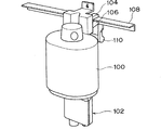
レーザレベルは水平面あるいは鉛直面に沿ってレーザ光を照射することができるため、例えば、建築現場などにおいて、天井の墨出し、ドア、窓の垂直出しなどの作業を行うときに利用されている。天井の墨出しを行う場合、図14に示すように、レーザレベル(レーザ墨出し機)100を保持するためのアダプタ(保持具)102の支持板104と支持板106との間に、壁面から突出されたアングル108を挿入し、支持板104と支持板106でアングル108を挟んだ後、レバー110を回動操作し、この回動操作による押圧力を支持板104、106に作用させて、アングル108をクランプし、レーザレベル100をアダプタ102を介して壁面に固定する構成が採用されている(特許文献1参照)。しかし、アダプタ100の場合、支持板104と支持板106との距離を十分に長くすることができず、しかも、レバー110の回動操作による押圧力を支持板106全体に作用させているので、板厚の厚い梁等をクランプするには十分ではない。
Since the laser level can irradiate laser light along a horizontal plane or a vertical plane, the laser level is used, for example, at a construction site or the like when performing work such as marking a ceiling, vertically exposing a door, or a window. When inking the ceiling, as shown in FIG. 14, between the
そこで、図15に示すように、レーザレベル(レーザ測量機)120を保持するアダプタ122として、スライド板124と、支持板126のねじ部に噛合されたクランプ用ねじ128とを備えたものが提案されている(特許文献2参照)。このアダプタ122は、スライド板124が広範囲に渡ってスライドするため、壁130に固定されたアングル132をクランプするときには、支持板126とスライド板124との間隔を狭くすることで、ねじ128とスライド板124でアングル132をクランプすることができる。一方、梁134をクランプするときには、支持板126とスライド板124との間隔を広げた後、ねじ128とスライド板124で梁134をクランプすることができる。
前記従来技術のうち後者のものは、スライド板124が広範囲に渡ってスライド可能に構成されているため、板厚の薄いアングル130や板厚の厚い梁132をクランプすることができる。しかし、アングル130や梁132をクランプするときに、一本のねじ128を回転操作して一点でクランプするようにしているため、ねじ128の締め付け状態によってはレーザレベル120が不安定な状態で固定されることがある。さらに、ねじ128を回転操作しなけらばならないので、クランプ作業が面倒である。
In the latter of the prior arts, since the
本発明は、前記従来技術の課題に鑑みて為されたもので、その目的は、レーザレベルを安定した状態でクランプ対象に固定することにある。 The present invention has been made in view of the above-described problems of the prior art, and an object thereof is to fix a laser level to a clamp target in a stable state.
前記目的を達成するために、請求項1に係るレーザレベル用アダプタにおいては、レーザレベルを支持するための軸状部材と、前記軸状部材のうち前記レーザレベルに相対向させるためのレーザレベル対向面側に前記軸状部材の軸方向と交差する方向に沿って配置されたレーザレベル固定板と、前記軸状部材のうち前記レーザレベル対向面の背面となるクランプ対象の対向面側に前記軸状部材の軸方向と交差する方向に沿って配置されたスライド板と、前記軸状部材のクランプ対象の対向面側において前記スライド板と相対向して配置されて前記軸状部材に固定されたクランプ用固定板と、前記レーザレベル対向面を囲む領域を第1の移動領域として前記軸状部材の軸方向に沿って往復動自在に配置されて前記レーザレベル固定板に連結された第1のスライダと、前記クランプ対象の対向面を囲む領域を第2の移動領域として前記軸状部材の軸方向に沿って往復動自在に配置されて前記スライド板に連結された第2のスライダと、前記スライド板の両端側に分かれて装着されて前記クランプ用固定板と前記スライド板との間に挿入されたクランプ対象をクランプする複数のクランプ機構とを備えて構成した。 To achieve the above object, in the laser level adapter according to claim 1, a shaft-shaped member for supporting the laser level and a laser level facing for opposing the laser level of the shaft-shaped member. A laser level fixing plate disposed on the surface side along a direction intersecting the axial direction of the shaft-shaped member, and the shaft on the facing surface side of the clamp target that is the back surface of the laser-level facing surface of the shaft-shaped member. A slide plate disposed along a direction intersecting the axial direction of the shaft-shaped member, and disposed opposite to the slide plate on the opposed surface side of the shaft-shaped member to be clamped and fixed to the shaft-shaped member. A clamp fixing plate and a region surrounding the laser level facing surface are disposed as a first moving region so as to be reciprocable along the axial direction of the shaft-like member and coupled to the laser level fixing plate. A first slider and a second slider connected to the slide plate and reciprocally moved along the axial direction of the shaft-like member with a region surrounding the opposing surface to be clamped as a second movement region And a plurality of clamp mechanisms that are mounted separately on both ends of the slide plate and clamp the clamp target inserted between the clamp fixing plate and the slide plate.
(作用)クランプ用固定板に相対向して配置されたスライド板が第2のスライダに連結されているので、第2のスライダを軸状部材の軸方向に沿ってスライド(往復動)させることで、クランプ用固定板とスライド板との間隔を調整することができ、クランプ対象として板厚の薄いもの、あるいは板厚の厚いものをクランプ対象にすることができる。そして、クランプ用固定板とスライド板との間に挿入されたクランプ対象物をクランプするときには、スライド板の両端側に別れて装着された各クランプ機構を操作することで、クランプ対象物が2点でクランプされるため、簡単な操作でクランプ対象物を安定した状態でクランプすることができる。クランプ対象物がクランプされた後は、レーザレベル固定板にレーザレベルを固定し、第1のスライダを軸状部材の軸方向に沿ってスライドさせることで、レーザレベルの位置を調整することができる。第1のスライダの位置が固定されると、レーザレベルはアダプタとクランプ対象物を介して壁等に安定した状態で固定されることになる。 (Operation) Since the slide plate arranged opposite to the clamp fixing plate is connected to the second slider, the second slider is slid (reciprocated) along the axial direction of the shaft-like member. Thus, the distance between the clamp fixing plate and the slide plate can be adjusted, and a thin plate or a thick plate can be clamped. And when clamping the clamp object inserted between the fixed plate for clamping and the slide plate, the clamp object is separated by operating each clamp mechanism separately attached to both ends of the slide plate. Therefore, the clamp object can be clamped in a stable state by a simple operation. After the clamping object is clamped, the laser level can be adjusted by fixing the laser level to the laser level fixing plate and sliding the first slider along the axial direction of the shaft-like member. . When the position of the first slider is fixed, the laser level is fixed in a stable state to the wall or the like via the adapter and the clamp object.
請求項2においては、請求項1に記載のレーザレベル用アダプタにおいて、前記軸状部材には、前記スライド板の移動範囲において前記第1の移動領域と前記第2の移動領域とを結ぶレーザ光照射用貫通孔が軸方向に沿って形成されるように構成した。 According to a second aspect of the present invention, in the laser level adapter according to the first aspect, the shaft-like member has a laser beam that connects the first moving region and the second moving region in the moving range of the slide plate. The irradiation through-hole was configured to be formed along the axial direction.
(作用)アダプタに支持されたレーザレベルから壁面に向けてレーザ光を照射する過程で、第2のスライダを用いてレーザレベルを支柱の軸方向に沿ってスライドするときに、レーザレベルから照射されたレーザ光がレーザ光照射用貫通孔を介して壁面に照射されるため、壁面に照射されたレーザ光の位置をレーザ光照射用貫通孔から確認することで、レーザレベルの位置決めを容易に行うことができる。 (Operation) In the process of irradiating the laser beam from the laser level supported by the adapter toward the wall surface, when the laser level is slid along the axial direction of the support column using the second slider, the laser level is irradiated from the laser level. Since the laser beam is irradiated to the wall surface through the laser beam irradiation through hole, the laser level can be easily positioned by checking the position of the laser beam irradiated on the wall surface from the laser beam irradiation through hole. be able to.
以上の説明から明らかなように、請求項1に係るアダプタによれば、レーザレベルを安定した状態でクランプ対象物に固定することができる。また、クランプ用固定板に固定されたレーザレベルを横置きとして、軸状部材を介して床等に設定したときに、レーザレベルから床等に対して垂直となるレーザ光を照射することで、ドア、窓等の垂直出しを行うことができる。さらに、レーザレベルから床等にレーザ光を照射するときに、床等に照射されるレーザ光の位置を確認しながら第1のスライダをスライドさせることで、レーザレベルの位置を容易に、かつ正確に調整することができる。 As apparent from the above description, according to the adapter according to claim 1, it is possible to fix the laser level to the clamp object in a stable state. Also, when the laser level fixed to the clamp fixing plate is set horizontally and set on the floor or the like via the shaft-like member, by irradiating the laser beam perpendicular to the floor or the like from the laser level, The doors and windows can be placed vertically. Furthermore, when irradiating the floor or the like with laser light from the laser level, the position of the laser level can be easily and accurately slid by sliding the first slider while checking the position of the laser light applied to the floor or the like. Can be adjusted.
請求項2によれば、レーザレベルの位置決めを容易に行うことができる。 According to the second aspect, the laser level positioning can be easily performed.
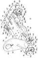
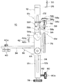
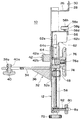
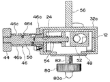
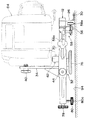
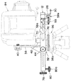
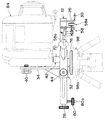
次に、本発明の実施形態を、実施例に基づいて説明する。図1は本発明の一実施例を示すレーザレベル用アダプタの斜視図、図2は同じく正面図、図3は同じく側面図、図4は同じく背面図、図5は同じく平面図、図6は図2のA−A線に沿う断面図、図7は図2のB−B線に沿う断面図である。 Next, embodiments of the present invention will be described based on examples. 1 is a perspective view of a laser level adapter according to an embodiment of the present invention, FIG. 2 is a front view, FIG. 3 is a side view, FIG. 4 is a rear view, FIG. 5 is a plan view, and FIG. 2 is a cross-sectional view taken along the line AA in FIG. 2, and FIG. 7 is a cross-sectional view taken along the line BB in FIG.
これらの図において、レーザレベル用アダプタ10は、レーザレベル(図示せず)を支持するための支柱12を備えており、支柱12は、例えば、アルミニウムを用いて、その断面がコ字状に形成された軸状部材として構成されている。支柱12の正面は、レーザレベルに相対向させるためのレーザレベル対向面12aとし設定され、支柱12の裏面(背面)は、壁などに固定されたアングルなどのクランプ対象に相対向させるためのクランプ対象対向面12bとして設定されている。レーザレベル対向面(正面)12aには、基準ラインとしての溝14と、オフセットラインとしての溝16が支柱12の軸心と直交する方向に沿って形成されているとともに、目盛ステッカ(センチメートルcmとインチinchによる目盛)18が固着されている。支柱12の上部側にはレーザ光照射用貫通孔(長孔)20が支柱12の軸方向に沿って形成されており、支柱12の側面にはガイド孔22、24が支柱12の軸方向に沿って形成されている。さらに支柱12の上部側にはクランプ用固定板26が支柱12に一体となって固着されている。
In these drawings, the
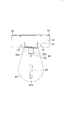
クランプ用固定板26は、断面形状が略L字状に形成されて、支柱12の軸方向と交差する方向、例えば、直交する方向に沿って配置されている。このクランプ用固定板26には、ロープ挿入用貫通孔27が2個形成されているとともに、取付孔28が3個互いに離れて形成されており、固定板26の両端側にはねじ30が固定されている。3個の取付孔28のうち真ん中の取付孔28は、支柱12の軸心の延長線上に形成されており、残りの2個の取付孔28は、真ん中の取付孔28から互いに等しい距離の位置に形成されている。また各ねじ30はクランプ用固定板26の上部側に支柱12から離れる方向に突出した状態で固定されている。
The
支柱12のレーザレベル対向面12aは平板状に形成されており、このレーザレベル対向面12a上にはスライダ(第1のスライダ)32が往復動自在(摺動自在)に配置されている。スライダ32は、レーザレベル対向面12aを囲む領域を移動領域(第1の移動領域)12cとして支柱12の軸方向に沿って往復動自在に支柱12に装着されている。
The laser
スライダ32は、略箱形形状に形成されて、支柱12に往復動自在に装着された本体32aを備えており、本体32aの正面側にはレーザレベル固定板34が固定されいる。レーザレベル固定板34は略平板状に形成されて、支柱12の軸方向と交差する方向、例えば、直交する方向に沿って配置されて、その底面側が、三角形形状の支持板36で支持された状態で本体32aに固定されている。レーザレベル固定板34には、レーザレベルを取り付けるための取付孔38が、長孔として、支柱12の軸心と直交する線に沿って形成されており、この取付孔38の端部にはねじ部38aが形成されている。このねじ部38aには、レーザレベル固定板32にレーザレベルを固定するための固定用ノブ40のねじ部40aが着脱自在に噛み合わされている。また本体32aにはレーザレベルをその底面側から支持するための機械支え42が固定されている。機械支え42は、樹脂を用いて略円柱状に形成された支持体42aと、支持体42aの頂部側に形成された凹部内に挿入されて、支持体42aの頂面からわずかに突出されたゴム製の円板42bとを備えて構成されている。
The
さらに、本体32aの側面側には操作ノブ44を支持するための支持体46が固定されており、本体32aの背面側にはガイド箱48が固定されている。支持体46は、円環状のベース46aと、円筒状に形成された筒体46bとが一体となって構成されて、ベース46aが本体32aに固定されている。筒体46bには、アンロック用の溝46cとロック用の溝46dとを結ぶクランク溝46eが形成されており、支持体46内には、操作ノブ44に連結されたシャフト50が摺動自在に挿入されている。
Further, a
シャフト50は、図7に示すように、ガイド孔24内に挿入されているとともに、ガイド箱48内に挿入されている。このシャフト50の外周面には、クランク溝46eに沿って移動可能に形成された位置決め用のピン50a固着されている。また、シャフト50の先端側は、ガイド箱48内に摺動自在に収納されたスライド板52に連結されており、シャフト50の外周側にはコイルスプリング54が装着されている。コイルスプリング54はスライド板52とガイド箱48の壁面との間に装着されており、操作ノブ44のアンロック操作により、ピン50aがアンロック用の溝46c内に挿入されたときには、スライド板52が操作ノブ44側に移動することに伴ってコイルスプリング54が縮小して、ガイド箱48と本体32aとの圧接が解除されるようになっている。この場合、スライダ32がアンロック状態となって支柱32の軸方向に沿って摺動可能になる。なお、ガイド箱48には調整ねじ56を挿入するための貫通孔(図示せず)が形成されており、スライダ32が支柱12の軸方向に沿って往復動、あるいは上下動するときに、ガイド箱48が調整ねじ56に沿って移動するとともに、シャフト50がガイド孔24に沿って移動できるようになっている。
As shown in FIG. 7, the
一方、操作ノブ44がロック操作されて、ピン50aが溝46cの位置からクランク溝46eを介して溝46dの位置まで移動したときには、シャフト50の移動に伴って、スライド板52が操作ノブ44から離れる方向に移動し、コイルスプリング54が伸び、コイルスプリング54の付勢力によってガイド箱48と本体32aとが圧接される。これにより、スライダ32がロック状態となって、指定の位置に固定されることになる。
On the other hand, when the
支柱12のクランプ対象の対向面(背面)12b側にはクランプ用固定板26と相対向してスライド板56が配置されている。スライド板56は、断面形状が略L字形状に形成されて、支柱12の軸方向と交差する方向、例えば、直交する方向に沿って配置されている。スライド板56の両端側にはそれぞれクランプ機構としてのトグルクランプ58が装着されている。各トグルクランプ58は、レバー58a、リンク58b、58c、ロッド58d、押付具58e、支持板58fを備えて構成されている。リンク58b、58cは互いに交差する方向に配置されて補助リンク58iを介して互いに連結されているとともに、各軸方向端部が支持板58fに連結されている。支持板58fはスライド板56の底部側に固定されている。リンク58bの軸方向端部にはレバー58aが装着され、リンク58cの軸方向端部にはロッド58dが固定されている。ロッド58dは、スライド板56に形成された孔60(図1参照)内に挿入されており、ロッド58dの軸方向端部に押付具58eが固定されている。押付具58eは、樹脂を用いて略円柱状に形成された支持体58gと、支持体58gの頂部側に形成された凹部内に装着されたゴム製の円板58hとを備えて構成されている。
A
各トグルクランプ58は、レバー58aが、図3に示す位置(支柱12と平行な位置)から正面側(レーザレベル固定板34側)に回動操作されたときに解除状態になる。一方、クランプ用固定板26とスライド板56との間にクランプ対象として、例えば、アングルが挿入されたときに、レバー58aが正面側から背面側に回動操作されて、図3に示す位置(支柱12と平行な位置)になると、レバー58aを回動操作したときの操作力がリンク58b、補助リンク58i、リンク58cを介してロッド58dに伝達され、押付具58eがアングルを固定板26側に押し付けて、クランプさせるようになっている。
Each
すなわち、本実施例においては、アングルなどのクランプ対象を複数のトグルクランプ58を用いて2点でクランプするように構成されている。また、クランプ対象をクランプするために、レバー58aを回動操作したときには、補助リンク58iがリンク58cと当接して、その移動が阻止されるようになっている。さらに、レバー58aがクランプを解除する方向に回動操作されたときには、押付具58eがスライド板56に当接して、その移動が阻止されるようになっている。即ち、レバー58aがクランプを解除する方向に回動操作されたときに、レバー58aがレーザレベル側(支柱12の正面側)に所定距離以上移動するのを阻止するようになっている。これによりレバー58aが支柱12の正面側に突出してレーザレベルに干渉するのを防止することができる。
That is, in the present embodiment, a clamp target such as an angle is clamped at two points using a plurality of toggle clamps 58. Further, when the
また、クランプ用スライド板56はスライダ(第2のスライダ)62に連結されている。スライダ62は、クランプ対象対向面12bを囲む領域を移動領域(第2の移動領域)12dとして、支柱12の軸方向に沿って往復動自在(摺動自在)配置されて、支柱12に装着されている。スライダ62は、平板状に形成されたスライド板62aと、スライド板62aの両側面側に一体となって形成された一対のスライド板62b、62cを備えて構成されており、スライド板62aとスライド板62b、62cの軸方向端部がクランプ用スライド板56に一体となって連結されている。スライド板62aの中央部には長孔62dが軸方向に沿って形成されている。スライド板62cには、図6に示すように、ガイド孔62eが軸方向に沿って形成されており、ガイド孔62e内には、支柱12の側面側に固定されたガイド板64のガイドピン64aが挿入されている。スライダ62のスライド板62cは、ガイド板64を支柱12に固定するためのガイドピン64aにガイドされた状態で摺動自在に支柱12に装着されている。
The
一方、スライド板62bには2枚のねじ受け板66、68が装着されており、各ねじ受け板66、68の中央部に形成された貫通孔(図示せず)内には操作ノブ70に連結されたシャフト72が挿入されている。ねじ受け板68の貫通孔にはねじ部が形成されており、このねじ部はシャフト72の先端側に形成されたねじ部と噛合うようになっている。即ち、操作ノブ70をアンロック方向に回転操作すると、ねじ受け板68がねじ受け板66から離れる方向に移動し、スライド板62bとねじ受け板66との圧接状態が解除され、スライダ62が支柱12の軸方向に沿ってスライド可能になる。
On the other hand, two
一方、操作ノブ70をロック方向に操作すると、シャフト72のねじ部とねじ受け板68のねじ部との噛合いによってねじ受け板68がねじ受け板66側に移動し、操作ノブ70に作用する操作力によってねじ受け板66がスライド板62bに圧接されて、スライダ62の移動が阻止され、スライダ62が指定の位置に固定されるようになっている。なお、シャフト72は、支柱12のガイド孔22内に挿入され、ガイド孔22に沿って移動可能になっている。
On the other hand, when the
また、支柱12の中央部には支持台74が固定されており、支持台74には三脚取付板76が固定されている。三脚取付板76は略円盤状に形成されており、三脚取付板76の中央部には、ねじ部76aが形成され、外周側には、三脚の平面脚頭を支持するための平面部(図示せず)、三脚の球面脚頭を支持するための球面部(図示せず)が形成されている。
A
また、支柱12の軸方向下端部には微動操作ノブ78が装着されており、微動操作ノブ78は調整ねじ56の軸方向端部に連結されている。微動操作ノブ78は、操作ノブ44のロック操作によってスライダ32がロックされたときに、ガイド箱48のねじ部と噛合い、スライダ32の位置を微調整できるようになっている。
A fine
また、支柱12の軸方向下端部には支柱12と壁面との距離を調整するための操作ノブ80が装着されており、操作ノブ80はシャフト82の軸方向端部に固定されている。シャフト82の外周側にはねじ部82aが形成されており、このねじ部82aは支柱12に形成された貫通孔内のねじ部(図示せず)と噛合うように構成されている。操作ノブ80を回転操作すると、シャフト82が支柱12と直交する方向に沿って移動するので、操作ノブ80の先端部80aと支柱12のクランプ対象の対向面12bとの距離を調整できるようになっている。即ち、クランプ用固定板26のねじ30と操作ノブ80の先端部80aを壁面に当てたときに、操作ノブ80を回転操作することで、壁面と支柱12のクランプ対象対向面12bとの距離が調整され、支柱12が壁面に対して垂直になるように調整できるようになっている。
Further, an
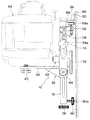
次に、アダプタ10の使用方法を図8に基づいて説明する。まず、レーザレベル84を壁86に固定するに際して、壁86の壁面に薄い板状のアングル88が形成されているときには、アングル88をクランプ対象として、支柱12のクランプ対象の対向面12bを壁面に向けてクランプ用固定板26とスライド板56との間にアングル88を挿入する。このあとクランプ用固定板26のねじ30を壁面に当接させるとともに、操作ノブ80の先端部80aを壁面に当接させる。このとき支柱12が壁面と略平行になっているときには、スライダ62を上昇移動させて、トグルクランプ58の押付具58eをアングル88の底面側に当接させる。このとき操作ノブ70を操作してスライダ62を支柱12に固定する。このあと各トグルクランプ58のレバー58aを順番にクランプ方向(正面側から壁86の方向)に操作して、各トグルクランプ58によってアングル88を2点でクランプする。
Next, the usage method of the
次に、レーザレベル固定板34上にレーザレベル84を装着し、固定用ノブ40を操作してレーザレベル84をレーザレベル固定板34上に固定する。このあと操作ノブ44をアンロック状態に操作してスライダ32を支柱12の軸方向に沿って移動させる。この際レーザレベル84から壁面に向けてレーザ光を照射するときに、レーザ光の照射位置をレーザ光照射用貫通孔20を介して確認しながらスライダ32をスライドさせることで、レーザレベル84の位置を容易に、かつ正確に調整することができる。そしてレーザレベル84をオフセット位置(基準ラインから2インチの位置)にセットするときには、レーザ光が溝16に沿って照射されるように、スライダ32の位置を調整し、レーザ光が溝16に沿って照射されたときには、その位置にスライダ32を固定することで、レーザレベル84をオフセット位置に固定することができる。スライダ32の位置が決定されたあとは、天井に対して鉛直方向に沿って配置された墨出し用の治具(標尺)に向けてレーザレベル84からレーザ光を照射することで、天井の墨出しを行うことができる。
Next, the
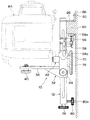
一方、図9に示すように、壁86にアングル88よりも板厚の厚い梁90が形成されているときには、クランプ用固定板26とスライド板56との間隔を最大にした状態でクランプ用固定板26とスライド板56との間に梁90を挿入する。このあとクランプ用固定板26のねじ30を壁面に当接させるとともに、操作ノブ80の先端部80aを壁面に当接させる。このあとスライダ62を上方にスライドさせて、トグルクランプ58の押付具58eを梁90の底面に当接させる。このあと操作ノブ70を操作してスライダ62を固定し、各トグルクランプ58のレバー58aをクランプ方向(正面側から壁86の方向)に操作して、各トグルクランプ58によって梁90を2点でクランプする。
On the other hand, as shown in FIG. 9, when a
本実施例によれば、レーザレベル84を壁86の壁面に固定する際に、クランプ対象が板厚の薄いアングル88や、板厚の厚い梁90であっても、レーザレベル84を壁面に固定することができるとともに、レーザレベル84を支持するための支柱12を、クランプ用固定板26とスライド板56を介して壁面に固定するときに、一対のトグルクランプ58でクランプ対象を2点でクランプするようにしたため、レーザレベル84を常に安定した状態でクランプ対象に固定することができる。さらに、各トグルクランプ58を支柱12の正面側から背面側に回動操作するだけで、いわゆる、ワンタッチ操作で、クランプ対象をクランプすることができるので、ねじを回しながらクランプするときよりも、クランプ操作を容易に行うことができる。
According to the present embodiment, when the
また、壁86のアングル88や梁90が固定されていないときには、図10に示すように、クランプ用固定板26の取付孔28内にビス92を挿入して、クランプ用固定26をビス92を介して壁86に固定する方法を採用することもできる。
Further, when the
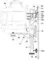
また、レーザレベル84を床に設置するときには、図11に示すように、支柱12を床94の壁面に沿って配置する。この場合、支柱12はクランプ用固定板26のねじ30と操作ノブ80の先端部80aが床94と接触した状態で床面に設置されることになる。このとき、レーザレベル84は横置きとして、レーザレベル固定板34に固定用ノブ40の操作によって固定されるとともに、底面側が機械支え42で支持された状態で固定される。この場合、レーザレベル84から床94に対して垂直となるレーザ光を照射することで、ドア、窓などの垂直出しを行うことできる。また、レーザレベル84から床94に向けてレーザ光を照射するときに、床94に照射されたレーザ光の照射位置をレーザ光照射用貫通孔20を介して確認しながらスライダ32をスライドさせることで、レーザレベル84の位置を容易に、かつ正確に調整することができる。
Further, when the
レーザレベル82の三脚に固定する際には、図12に示すように、三脚96として、球面脚頭96aを有するときには、三脚取付板76の球面部に球面脚頭96aを装着し、三脚96のねじをねじ部76aに噛合わせて、支柱12を三脚取付板76を介して三脚96に固定する。この場合、レーザレベル84は横置きとしてアダプタ10に支持され、レーザレベル84から支柱12の軸方向と直交する方向のレーザ光を照射することで、ドアや窓の垂直出しなどを行うことができる。
When fixing to the tripod of the
また、図13に示すように、三脚98として、平面脚頭98a有するものにレーザレベル84を固定するときには、三脚取付板76の平面部を平面脚頭98aに装着させ、このあと三脚98のねじをねじ部76aに噛合わせることで、レーザレベル84をアダプタ10を介して三脚98に固定することができる。この場合も、レーザレベル84は横置きとして、アダプタ10に支持され、レーザレベル84から支柱12の軸方向と直交する方向のレーザ光を照射することで、ドアや窓の垂直出しなどを行うことができる。
As shown in FIG. 13, when fixing the
10 アダプタ
12 支柱
26 クランプ用固定板
32 スライダ
34 レーザレベル固定板
56 スライド板
58 トグルクランプ
62 スライダ
10
Claims (2)
Priority Applications (1)
| Application Number | Priority Date | Filing Date | Title |
|---|---|---|---|
| JP2004113541A JP4514495B2 (en) | 2004-04-07 | 2004-04-07 | Laser level adapter |
Applications Claiming Priority (1)
| Application Number | Priority Date | Filing Date | Title |
|---|---|---|---|
| JP2004113541A JP4514495B2 (en) | 2004-04-07 | 2004-04-07 | Laser level adapter |
Publications (2)
| Publication Number | Publication Date |
|---|---|
| JP2005297096A true JP2005297096A (en) | 2005-10-27 |
| JP4514495B2 JP4514495B2 (en) | 2010-07-28 |
Family
ID=35329266
Family Applications (1)
| Application Number | Title | Priority Date | Filing Date |
|---|---|---|---|
| JP2004113541A Expired - Fee Related JP4514495B2 (en) | 2004-04-07 | 2004-04-07 | Laser level adapter |
Country Status (1)
| Country | Link |
|---|---|
| JP (1) | JP4514495B2 (en) |
Cited By (9)
| Publication number | Priority date | Publication date | Assignee | Title |
|---|---|---|---|---|
| KR101925615B1 (en) * | 2017-06-26 | 2018-12-05 | 장미희 | Wall mount assembly for laser leveler |
| CN109128845A (en) * | 2018-10-17 | 2019-01-04 | 东莞市鹏轩机电科技有限公司 | A lathe with a laser head |
| JP2020196096A (en) * | 2019-06-04 | 2020-12-10 | 株式会社Fuji | Detachable workpiece temporary receiver |
| CN113043237A (en) * | 2021-04-22 | 2021-06-29 | 宁夏恒泰化工设备有限公司 | Marking device for welding impact sample of pressure vessel |
| WO2022065982A1 (en) * | 2020-09-28 | 2022-03-31 | 주식회사 리츠 | Method for providing scanner inside silo or bin, and scanner provision device that is usable in method |
| WO2023009786A1 (en) | 2021-07-30 | 2023-02-02 | Milwaukee Electric Tool Corporation | Laser level mounting device |
| WO2023084328A1 (en) * | 2021-11-11 | 2023-05-19 | Cantillo Fernandez Juan Carlos | Alignment system |
| KR20240000205U (en) * | 2022-07-28 | 2024-02-06 | 주식회사 에임비랩 | Apparatus for measuring feed |
| EP4377635A4 (en) * | 2021-07-30 | 2025-08-27 | Milwaukee Electric Tool Corp | LASER LEVEL MOUNTING JIG |
Citations (3)
| Publication number | Priority date | Publication date | Assignee | Title |
|---|---|---|---|---|
| JPH09210687A (en) * | 1996-01-31 | 1997-08-12 | Topcon Corp | Laser level device |
| JP2005098736A (en) * | 2003-09-22 | 2005-04-14 | Mitsubishi Automob Eng Co Ltd | Dimension measuring method using laser floodlight and installing fixture for laser floodlight |
| JP2007517676A (en) * | 2004-01-06 | 2007-07-05 | ザ・ボーイング・カンパニー | Laser guided adjustment hole drilling |
-
2004
- 2004-04-07 JP JP2004113541A patent/JP4514495B2/en not_active Expired - Fee Related
Patent Citations (3)
| Publication number | Priority date | Publication date | Assignee | Title |
|---|---|---|---|---|
| JPH09210687A (en) * | 1996-01-31 | 1997-08-12 | Topcon Corp | Laser level device |
| JP2005098736A (en) * | 2003-09-22 | 2005-04-14 | Mitsubishi Automob Eng Co Ltd | Dimension measuring method using laser floodlight and installing fixture for laser floodlight |
| JP2007517676A (en) * | 2004-01-06 | 2007-07-05 | ザ・ボーイング・カンパニー | Laser guided adjustment hole drilling |
Cited By (13)
| Publication number | Priority date | Publication date | Assignee | Title |
|---|---|---|---|---|
| KR101925615B1 (en) * | 2017-06-26 | 2018-12-05 | 장미희 | Wall mount assembly for laser leveler |
| CN109128845A (en) * | 2018-10-17 | 2019-01-04 | 东莞市鹏轩机电科技有限公司 | A lathe with a laser head |
| JP7349267B2 (en) | 2019-06-04 | 2023-09-22 | 株式会社Fuji | Removable workpiece temporary holder |
| JP2020196096A (en) * | 2019-06-04 | 2020-12-10 | 株式会社Fuji | Detachable workpiece temporary receiver |
| WO2022065982A1 (en) * | 2020-09-28 | 2022-03-31 | 주식회사 리츠 | Method for providing scanner inside silo or bin, and scanner provision device that is usable in method |
| CN113043237A (en) * | 2021-04-22 | 2021-06-29 | 宁夏恒泰化工设备有限公司 | Marking device for welding impact sample of pressure vessel |
| CN113043237B (en) * | 2021-04-22 | 2022-12-27 | 宁夏恒泰化工设备有限公司 | Marking device for welding impact sample of pressure vessel |
| WO2023009786A1 (en) | 2021-07-30 | 2023-02-02 | Milwaukee Electric Tool Corporation | Laser level mounting device |
| EP4377635A4 (en) * | 2021-07-30 | 2025-08-27 | Milwaukee Electric Tool Corp | LASER LEVEL MOUNTING JIG |
| US12516931B2 (en) | 2021-07-30 | 2026-01-06 | Milwaukee Electric Tool Corporation | Laser level mounting device |
| WO2023084328A1 (en) * | 2021-11-11 | 2023-05-19 | Cantillo Fernandez Juan Carlos | Alignment system |
| KR20240000205U (en) * | 2022-07-28 | 2024-02-06 | 주식회사 에임비랩 | Apparatus for measuring feed |
| KR200499482Y1 (en) | 2022-07-28 | 2025-08-14 | 주식회사 에임비랩 | Apparatus for measuring feed |
Also Published As
| Publication number | Publication date |
|---|---|
| JP4514495B2 (en) | 2010-07-28 |
Similar Documents
| Publication | Publication Date | Title |
|---|---|---|
| JP4514495B2 (en) | Laser level adapter | |
| KR102142201B1 (en) | Wedge drive | |
| JP2016205592A (en) | Slide guide unit and measurement device | |
| JP3504623B2 (en) | Screen printing device and screen plate setting method | |
| RU2370607C2 (en) | Curb system | |
| CN116719140B (en) | Multi-axis adjusting device for micron-sized optical slit | |
| JP3144575U (en) | 2 axis plane moving stage | |
| JP5700540B2 (en) | Optical device and optical measuring device | |
| JP3984961B2 (en) | X-ray imaging apparatus and light irradiator | |
| KR20180107493A (en) | Thickness gauge | |
| KR20210069870A (en) | Laser light source module and jig for manufacturing the same | |
| US20120041585A1 (en) | Adjustable locator for a workpiece fixture | |
| CN220985743U (en) | Camera focusing test platform | |
| JP2003057031A (en) | Floodlight projector unit of semiconductor laser | |
| JPH077142B2 (en) | Device for positioning the optical components of a Fourier transform infrared spectrophotometer | |
| JP2016082138A (en) | Stage device | |
| JP2626881B2 (en) | Vertical laser target | |
| JPH05297865A (en) | Enclosure structure of electronic musical instrument | |
| CN223870385U (en) | A sample holder for a cutting instrument | |
| JPH074541Y2 (en) | Tissue embedding cassette mounting table for microtome | |
| CN223712002U (en) | An automatic focusing mechanism for a lithography machine lens with a scanning actuation structure | |
| JPH07191246A (en) | Optical member holder | |
| KR102410614B1 (en) | Key vise and key duplicating device including the same | |
| JP3869750B2 (en) | Laser light emitting device | |
| JP4693229B2 (en) | Pachinko machine mounting device |
Legal Events
| Date | Code | Title | Description |
|---|---|---|---|
| A621 | Written request for application examination |
Free format text: JAPANESE INTERMEDIATE CODE: A621 Effective date: 20070124 |
|
| TRDD | Decision of grant or rejection written | ||
| A01 | Written decision to grant a patent or to grant a registration (utility model) |
Free format text: JAPANESE INTERMEDIATE CODE: A01 Effective date: 20100427 |
|
| A01 | Written decision to grant a patent or to grant a registration (utility model) |
Free format text: JAPANESE INTERMEDIATE CODE: A01 |
|
| A61 | First payment of annual fees (during grant procedure) |
Free format text: JAPANESE INTERMEDIATE CODE: A61 Effective date: 20100511 |
|
| R150 | Certificate of patent or registration of utility model |
Free format text: JAPANESE INTERMEDIATE CODE: R150 |
|
| FPAY | Renewal fee payment (event date is renewal date of database) |
Free format text: PAYMENT UNTIL: 20130521 Year of fee payment: 3 |
|
| FPAY | Renewal fee payment (event date is renewal date of database) |
Free format text: PAYMENT UNTIL: 20130521 Year of fee payment: 3 |
|
| S531 | Written request for registration of change of domicile |
Free format text: JAPANESE INTERMEDIATE CODE: R313531 |
|
| FPAY | Renewal fee payment (event date is renewal date of database) |
Free format text: PAYMENT UNTIL: 20130521 Year of fee payment: 3 |
|
| R350 | Written notification of registration of transfer |
Free format text: JAPANESE INTERMEDIATE CODE: R350 |
|
| FPAY | Renewal fee payment (event date is renewal date of database) |
Free format text: PAYMENT UNTIL: 20130521 Year of fee payment: 3 |
|
| FPAY | Renewal fee payment (event date is renewal date of database) |
Free format text: PAYMENT UNTIL: 20140521 Year of fee payment: 4 |
|
| LAPS | Cancellation because of no payment of annual fees |