JP2005297072A - Disc-shaped object reference position teaching method, positioning method, and transport method, and disc-shaped reference position teaching apparatus, positioning apparatus, transport apparatus, and semiconductor manufacturing equipment using these methods - Google Patents
Disc-shaped object reference position teaching method, positioning method, and transport method, and disc-shaped reference position teaching apparatus, positioning apparatus, transport apparatus, and semiconductor manufacturing equipment using these methods Download PDFInfo
- Publication number
- JP2005297072A JP2005297072A JP2002157393A JP2002157393A JP2005297072A JP 2005297072 A JP2005297072 A JP 2005297072A JP 2002157393 A JP2002157393 A JP 2002157393A JP 2002157393 A JP2002157393 A JP 2002157393A JP 2005297072 A JP2005297072 A JP 2005297072A
- Authority
- JP
- Japan
- Prior art keywords
- disk
- shaped object
- center position
- coordinate system
- reference coordinate
- Prior art date
- Legal status (The legal status is an assumption and is not a legal conclusion. Google has not performed a legal analysis and makes no representation as to the accuracy of the status listed.)
- Granted
Links
Images


Classifications
-
- H—ELECTRICITY
- H10—SEMICONDUCTOR DEVICES; ELECTRIC SOLID-STATE DEVICES NOT OTHERWISE PROVIDED FOR
- H10P—GENERIC PROCESSES OR APPARATUS FOR THE MANUFACTURE OR TREATMENT OF DEVICES COVERED BY CLASS H10
- H10P72/00—Handling or holding of wafers, substrates or devices during manufacture or treatment thereof
- H10P72/50—Handling or holding of wafers, substrates or devices during manufacture or treatment thereof for positioning, orientation or alignment
-
- B—PERFORMING OPERATIONS; TRANSPORTING
- B25—HAND TOOLS; PORTABLE POWER-DRIVEN TOOLS; MANIPULATORS
- B25J—MANIPULATORS; CHAMBERS PROVIDED WITH MANIPULATION DEVICES
- B25J9/00—Program-controlled manipulators
- B25J9/16—Program controls
- B25J9/1679—Program controls characterised by the tasks executed
- B25J9/1692—Calibration of manipulator
-
- B—PERFORMING OPERATIONS; TRANSPORTING
- B25—HAND TOOLS; PORTABLE POWER-DRIVEN TOOLS; MANIPULATORS
- B25J—MANIPULATORS; CHAMBERS PROVIDED WITH MANIPULATION DEVICES
- B25J9/00—Program-controlled manipulators
- B25J9/16—Program controls
-
- H—ELECTRICITY
- H10—SEMICONDUCTOR DEVICES; ELECTRIC SOLID-STATE DEVICES NOT OTHERWISE PROVIDED FOR
- H10P—GENERIC PROCESSES OR APPARATUS FOR THE MANUFACTURE OR TREATMENT OF DEVICES COVERED BY CLASS H10
- H10P72/00—Handling or holding of wafers, substrates or devices during manufacture or treatment thereof
- H10P72/50—Handling or holding of wafers, substrates or devices during manufacture or treatment thereof for positioning, orientation or alignment
- H10P72/53—Handling or holding of wafers, substrates or devices during manufacture or treatment thereof for positioning, orientation or alignment using optical controlling means
Landscapes
- Engineering & Computer Science (AREA)
- Robotics (AREA)
- Mechanical Engineering (AREA)
- Container, Conveyance, Adherence, Positioning, Of Wafer (AREA)
- Numerical Control (AREA)
- Manipulator (AREA)
Abstract
【課題】位置決め装置と搬送ロボットとを具える半導体製造装置における従来の設備立ち上げの際の各ポートでの基準位置教示が全て手動で、熟練技術者による長時間作業が必要であり、定常生産工程でも位置決め装置が必要でウエハの受け渡し、測定と時間が掛かり生産性が低いという問題を解決することにある。
【解決手段】ウエハ等の円盤状物47の円周と検出手段の軌跡43とが交わる2点W1, W2を検出し、この2点とこれらを結ぶ線分の垂直二等分線42上の特定点Oと円盤状物の半径rとを用いて円盤状物の中心位置Aを算出する。これにより搬送ロボットに位置決め作業をさせ、その結果を用いて搬送経路の修正ばかりでなく設備立ち上げの際の基準位置教示も大部分自動化できた。切り欠き部がある場合は、円盤状物の円周を検出手段の2本の軌跡で検出し、正しい中心位置を見いだす。また半径未知の円盤状物の円周を検出手段の3本の軌跡で検出して半径を求めることで、直径の異なるウエハを用いる混合生産も可能となった。
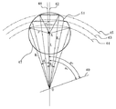
【選択図】 図4In a semiconductor manufacturing apparatus including a positioning device and a transfer robot, teaching of a reference position at each port at the time of starting up a conventional facility is all manual, requiring a long time operation by a skilled engineer, and steady production. In the process, a positioning device is required, and it is necessary to solve the problem that it takes time to transfer and measure the wafer, and the productivity is low.
SOLUTION: Two points W1 and W2 where the circumference of a disk-like object 47 such as a wafer and a trajectory 43 of a detection means intersect are detected, and the two bisects on a vertical bisector 42 connecting them. A center position A of the disk-like object is calculated using the specific point O and the radius r of the disk-like object. This allowed the transfer robot to perform positioning work, and using the results, not only correction of the transfer path but also the teaching of the reference position when starting up the equipment was largely automated. If there is a notch, the circumference of the disk-like object is detected by the two trajectories of the detection means to find the correct center position. Further, by detecting the circumference of a disk-like object having an unknown radius with three trajectories of the detecting means and obtaining the radius, mixed production using wafers having different diameters has become possible.
[Selection] Figure 4
Description
【0001】
【発明の属する技術分野】
本発明は、半導体ウエハ等の円盤状物を複数場所間で移送する等取り扱う際に必ず行う必要がある、その取扱装置の位置を含む基準座標系における円盤状物の位置の基準となる基準位置の教示のための方法および装置に関するとともに、その教示における中心位置の求め方を用いた位置決め方法および装置と、その位置決めを利用して搬送軌道を自動修正する搬送方法および装置とに関し、さらに、それらの装置を利用する半導体製造設備にも関するものである。
【0002】
【従来の技術】
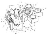
図1および図2に示すように、一般に半導体製造設備1は、半導体ウエハ等が棚段上に収納されているカセット6から各種多様な処理チャンバ7の搬送口であるロードロック室8へ、またそのロードロック室8から処理チャンバ7へとウエハを搬送ロボット4で搬送する又は搬送装置2を有している。この搬送ロボット4は、図3に示すように、ウエハ等を載置又は固定する保持部14を持つとともに屈伸、旋回および昇降動作することができる搬送アーム12を備えており、搬送ロボット4の各軸の動作は制御部11により制御されている。制御部11は、搬送ロボット4の位置座標を含む基準座標系における搬送の手順、経路および搬送位置の座標情報を記憶し、それを基に搬送ロボット4の各軸へと動作命令を出す。これにより搬送ロボット4はウエハ13等の円盤状物を所定の搬送位置へと自動的に搬送することができ、そのためには制御部11は、上記基準座標系での前記各種機器やウエハの位置座標をそれぞれ認識しておく必要がある。
【0003】
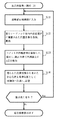
図26は、半導体製造設備1の立ち上げ時に原点座標を定めるための、図25に示す従来の搬送装置2における教示(ティーチング)工程のフローチャートの一部を示す。ここにおける「教示」とは、搬送ロボット4と、カセット6、ロードロック室8との間、必要ならば別途設ける位置決め装置10等との間でウエハ13等を受け渡しするための基準位置を決定するための作業である。
【0004】
例えば、カセット6に収納されているウエハ13等の円盤状物をロードロック室8へ搬送する工程に関して教示を行う場合、先ずステップS1で設計上の搬送ロボット4の仮位置情報(初期値)を制御部11に入力し、次いでステップS2により、基準位置としての、設計図面に基づいたカセット6との受け渡し位置へと、搬送ロボット4の保持部14を少しずつ手動操作(マニュアル)で移動させる。ただし、円盤状物はカセット6内の棚段の正常位置に載置されたままで、保持部14に固定されていない状態である。
【0005】
次いでステップS3で、図3に示すように、保持部14上に案内治具20を取り付け、円盤状物の載置位置と設計図上の保持位置とが完全に一致しているか否かを目視により確認する。ずれている場合はステップS4で、搬送ロボットを少しずつ手動操作で旋回、屈伸、昇降動作させて、保持部14の位置を適正な位置に修正し、続くステップS5で、ステップS4で得た位置情報を制御部11に伝達して初期位置情報を更新する。
【0006】
ステップS3での確認でずれが無い場合は、ステップS6で、保持した円盤状物をロードロック室8との受け渡し位置へ搬送し、次いでステップS7で、円盤状物の搬送位置が設計図面通りであるかを目視で確認する。実際の搬送位置にずれがある場合はステップS4へ戻ってステップS5へと進む。ずれがない場合、一連の教示は終了する。
【0007】
以下、搬送ロボット4に関しては位置決め装置10や他のカセット6、各ロードロック室8との間、また真空ロボット31に関しては各ロードロック室8や各処理チャンバ7等の他のポートとの間について、同様にステップS1からステップS7の手順に従って一つ一つ基準位置の教示作業を行っている。
【0008】
また、従来の生産工程中における、その都度の円盤状物の位置決めは、図25に示す如き位置決め装置(専用機)10を用いて行っている。図25に示す搬送装置2においては、搬送中のウエハ13の軌道がカセット6や各出入口の縁と干渉するのを防止するために、搬送ロボット4とは別途の円盤回転式位置決め装置10にウエハ13を一旦引き渡して正常位置に位置決めした後、再び搬送ロボット4がウエハ13を受け取って目的場所へ搬送するのが通常である。
【0009】
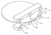
特公平7−27953号公報では、上記受け渡し工程を省略して生産性向上を図るために、ウエハを保持したまま搬送ロボットの搬送アームを動作させ、図27に示すような、各々発光部9aと受光部9bとを持ち光束9cでウエハ13を検出する3個のセンサ9が取り付けられた門型位置決め装置を通過させて、ウエハの中心位置を算出する方法を提案している。この方法では、ウエハの基準保持位置は予め教示してあり、教示位置と前記の門型位置決め装置で検出したウエハ中心位置との偏移量から保持部14の軌道を修正し、他の機器と干渉することなく目的場所に搬送する。これによって位置決め装置10に対する引き渡しと受け取りに要する時間が短縮され、上記方法は生産性の向上に寄与した。
【00010】
【発明が解決しようとする課題】
しかしながら、先に述べた従来の教示作業は、図26のフローチャートに示すように、搬送ロボット4が関与する全ての機器との間で、案内治具20を用いて黙視で確認しながら試行錯誤を繰り返し基準位置を設定するという、全手動方式のもので、非常に労力を要する方法である。これは熟練した技術者による緊張した作業の連続であるため、図25に示す搬送装置のみで、丸一日或いはそれ以上の時間が必要であった。
【0011】
また、生産中における円盤状物の位置決め用として、前述のように図27に示す特公平7−275953号公報記載の門型位置決め装置が提案されているが、ここでも初期の教示は前記従来の方法を用いるため、設備立ち上げに要する労力には何ら変わりはない。しかも、門を通過させる装置であるため各ロードロック室や各処理チャンバの入り口ごとに1台設置しなければならないという問題があり、またこの装置はウエハ等円盤状被検物の直径以上に大きな装置であるため投資額が大きくなるという問題があった。さらに、円盤状物を前記門型位置決め装置に挿入する前には位置決め工程がないため、円盤状物がこの装置に衝突しないように予め前述のような手間が掛かる手動による位置決めをしておく必要があった。そして万一衝突した場合は、ごみの発生は必定で、さらにウエハ等被検物の破損に繋がりかねないという問題もあった。
【0012】
さらに、上記特公平7−27953号公報記載の位置決め方法では、切り欠き部の判別の仕方は幾何学的には図示されているが、代数学的に判別する方法が見いだされていない。従って、近似式法である最少自乗法によって円盤中心を算出する方法をとるため、検出手段であるセンサ9を少なくとも3個必要とし、円盤の周縁上の少なくとも6点と円盤保持部の中心1点、合計少なくとも7点を測定しなければならない。しかも周縁上6点の中に、切り欠き部縁上にあって円周上にない点が必ず含まれ、厳密には正しい位置が算出されず精度が良くなかった。また、切り欠き部を含まない周縁上4点から、公知のピタゴラスの定理に基づいて円盤の半径を求める計算式を提示しているが、切り欠き部上の点を除外出来ないため、実際には正確な円盤半径を求めることはできなかった。
【0013】
【課題を解決するための手段】
本発明は、これらの問題点を解決するため鋭意検討した結果、新規、且つ、厳密な計算方法を開発してウエハ等円盤状物の中心位置の偏移量を測定、算出し、半導体設備の迅速な立ち上げを実現する新規な自動教示(オートティーチング)方法および位置決め方法を提案するものである。また、この理論に基づく教示装置、位置決め装置、算出した偏移量に基づいて搬送軌道の修正を行う搬送方法、搬送装置、さらにはこれらを利用した半導体設備をも提案するものである。ちなみに本発明でいう「教示」とは、円盤状物の搬送その他の取扱いを行う取扱装置の保持部等の動作の基準となる、円盤状物を置く場所の、その取扱装置の位置を含む基準座標系での位置座標である基準位置を、その取扱装置に入力して記憶させることをいい、また本発明における「位置決め」とは、保持部上等の任意の位置に載置された円盤状物やそれを保持する保持部等の位置が、先に入力された基準位置からどれだけずれているかを求めることをいう。
【0014】
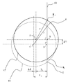
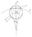
先ず始めに、本発明の原理を説明する。図4は、円盤の円周と1個のセンサの円弧状の軌跡とが交差する場合を示す。測定すべき円盤47は、既知半径rの上記円周とセンサの既知半径Rの円弧状の検出軌跡43との交点をW1 ,W2 、それらの交点間の上記円周の円弧の頂点をW3 とすると、円弧W1 W3 W2 を形成する。この円弧の両端が為す線分W1 W2 の垂直二等分線42は、測定円盤47の中心Aおよびセンサの円弧軌跡の中心Oの双方を通る。この垂直二等分線42と、予め教示した方向41との偏移角度αは、測定により求めることができる。また、垂直二等分線42と円弧の一端W1 との為す角度θも測定により求めることができる。
【0015】
次に測定円盤47の中心位置として、未知長さである線分AO(=L1 )を求める。W1 から垂直二等分線42の線分W3 Oに垂線を下ろしその交点をBとすると、
△W1 BOより、BO=Rcos θ,W1 B=Rsin θ ・・・(式1)
△W1 BAより、BO=rcos φ+ L1 ,W1 B=rsin φ・(式2)
即ち、Rcos θ=rcos φ+L1 ・・・・・・・・(式3)
Rsin θ=rsin φ ・・・・・・・・(式4)
移項して整理すると、rcos φ=Rcos θ−L1 ・・・・・(式5)
rsin φ=Rsin θ ・・・・・・・・(式6)
(式5)と(式6)を2乗し、左右両辺をそれぞれ加えると、
cos2φ+sin2φ=1だから、
r2 =(Rcos θ−L1)2 +R2sin2 θ ・・・・・(式7)
従って、L1 =Rcos θ±(r2 −R2sin2 θ)1/2 ・・・・(式8)
【0016】
ここで、図4の様にセンサの検出軌跡43に対し測定すべき円盤の中心Aがその検出軌跡の乗る円の内側にある場合は、
L1 =Rcos θ−(r2 −R2sin2 θ)1/2 ・・・・(式9)
外側にある場合は、
L1 =Rcos θ+(r2 −R2sin2 θ)1/2 ・・・(式10)
となる。
ここでは、予め教示した円盤46の中心位置Cは既知であるから、線分COをL0 とすると、
直径方向の偏移長さΔH=L1 −L0 ・・・・・・・(式11)
よって、前期偏移角度αと、(式11)による直径方向の偏移長さΔHとを用いて、円盤の位置決めをすることができる。
【0017】
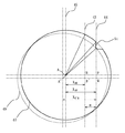
次に図5において、基準となる円盤状物46の円周を、1個のセンサの直線状の検出軌道43が円弧状に切る場合について説明する。予め教示した位置にある円盤46の円弧の両端が為す線分EFと、その垂直二等分線との交点をDとすると、中心Cとの距離CD(=X0)は予め教示してあるため判明している。
【0018】
同じく図5で、中心が未知の位置Aにある、既知半径rの測定すべき円盤状物47の円周を、センサの直線状検出軌道43によって円弧状に切る場合について述べる。前記円弧の両端点をW1 ,W2 とすると、線分W1 W2 の長さは測定により既知となる。線分W1 W2 の垂直二等分線とこの線分W1 W2 との交点をBとし、未知の距離AB=X1 とすると、
△ABW2 は直角三角形であるから、
X1 2+(BW2)2 =r2 ・・・・・・・(式12)
ここでBW2 =W1 W2 /2であるから、
X1 =±{r2 −(W1 W2 /2)2}1/2 ・・・・・(式13)
従って、X方向の偏移量は
ΔX=X0 −X1 ・・・・・・・(式14)
として算出される。
【0019】
ここで検知軌道43上のD点は教示位置であるから既知であり、B点は線分測定点W1 W2 の中点であるから測定により求まる。
従って、Y方向の偏移量
ΔY=BD ・・・・・・・(式15)
も測定により求まる。
よって偏移量(ΔX,ΔY)が算出される。
【0020】
請求項1および請求項2記載の発明は、前記原理を用いて基準位置を教示する方法に関する。即ち本発明は、円盤状物の取扱装置にその取扱装置の位置を含む基準座標系での前記円盤状物の位置の基準となる基準位置を教示する方法において、基準位置とする所定場所に半径既知の円盤状物を置く工程と、前記基準座標系での前記円盤状物の中心位置を求める工程と、前記中心位置に基づいて演算で求めた前記基準座標系での前記所定場所の位置を基準位置として前記取扱装置に記憶させる工程と、を含み、前記円盤状物の中心位置を求める工程が、前記円盤状物に対し検出手段を相対的に移動させて前記円盤状物の円周に対し前記検出手段の1本の軌跡を交叉させる工程と、前記交叉による2個の交点の、前記基準座標系での位置を求める工程と、前記2個の交点を結ぶ線分の垂直二等分線上の特定点と前記2個の交点と前記円盤状物の半径とを用いて前記中心位置を算出する工程と、を含むことを特徴とする円盤状物の基準位置教示方法を提案している。請求項7は、この方法を実現するための装置に関するものである。
【0021】
ここでの特定点とは、既知又は測定により定まる点と定義する。即ち、検出手段の軌跡が円である場合はこの円の旋回中心であり、これは既知である。また検出手段の軌跡が直線である場合は前記円周との2つの交点を結ぶ線分の中点で、測定により直ちに求まる。本教示方法においては、基準位置とする所定場所に円盤状物を置く時に、好ましくは手動で行い、その際、その円盤状物として市販のウエハを用いる場合には、好ましくはノッチやオリエンテーションフラットなどの凹部を検出軌道からさけて置くようにする。またウエハ以外の、凹部や凸部がない円盤状物を用いてもよい。なお、画像処理等で凸部や凹部の位置を自動的に認識して、自動的に凸部や凹部を検出軌道からさけて置くようにしてもよい。
【0022】
同様に前述の原理により、円盤状物に凹部や凸部がない場合、或いはこれらが上記のようにして避けられる場合について、1個の検出手段を用いて請求項3記載の円盤状物の位置決め方法および請求項9記載の位置決め装置を提案した。前述の教示装置および位置決め装置には、具体的形態として、公知のロボット、搬送装置、位置決め専用装置など、本発明の方法が機能として実現できる、すべての装置を含む。
本発明では、円盤状物を検出するためのセンサが固定され、円盤状物が運動してもよいし、或いは、円盤状物が固定され、センサが運動してもよい。また、この運動は直線運動でもよいし、円運動でもよい。
また、請求項3〜請求項5の方法においては、円盤状物の中心位置を予め教示する必要があるが、その際、請求項1または請求項2記載の方法を用いてもよいし、従来公知の方法を用いてもよい。
【0023】
〔切り欠き部をよける方法1〕
請求項4および請求項10記載の発明は、半導体ウエハのようにノッチやオリエンテーションフラット等の周縁上の基準場所としての切り欠き部(凹部)や、円盤に付けられた取手のような凸部がある場合について、その位置決め方法および位置決め装置を提案したものである。即ちここでは、円盤状物の中心位置を算出するに際し、図6に示すように、例えば2つの検出手段9を用いて異なる検出軌道43,44を設ける。検出軌道43が凹部である切り欠き部51を通った場合、そこに切り欠き部が無かった場合に比べて円盤の外周との2つの交点がなす線分は短くなり、前記計算法で算出すると円盤中心は旋回中心O寄りにあると算出される。
【0024】
さらに詳しく説明すると、検知軌道43,44が共に切り欠き部を通らなかった場合は、図6において、垂直二等分線42の左側2つの三角形から(式16)のように、円盤の中心Aと旋回中心Oとの距離は共にAOであると算出する。
【数1】

【数2】
【0025】
図7において、検出軌道44に切り欠き部がある場合も、同様にして大きい方の距離AOを選べばよい。
即ち、切り欠き部上を検出軌道が通れば、算出された円盤中心は必ず旋回中心O寄りにあって小さいと算出される。共には切り欠き部が入らないように2つの検出軌道を離間しておき、円盤の円周を2つの円弧状に切ってそれぞれの両端を測定し、旋回中心から見て外側にある円盤中心、即ち距離AOの値が大きい方を選べばよい。
ちなみに、2つの検出軌道43,44上にともに切り欠き部がない場合は、同じ場所に中心位置を見出すため、どちらを採用してもよい。
【0026】
〔切り欠き部をよける方法2、1つのセンサで2回通過する方法〕
請求項4では、次に図8,図9に示すように、1個のセンサと2回の旋回動作で2つの異なる円弧を形成させてもよい。即ち、円盤状物の中心を算出するに際し、旋回中心Oから検出軌道43までの距離Rはそのままに、2回目は円盤状物の中心位置を距離mだけずらして旋回する。ただし距離mは、2回の旋回動作で共には切り欠き部に掛らない程度に広げ、円盤の直径より狭い間隔とする必要がある。
【0027】
先ず、図8で検出軌道43が切り欠き部51を通らなかった場合と、通った場合とについて検出手順を説明する。先ず、検出軌道43が切り欠き部51に通らなかった場合は、垂直二等分線42の左側にある旋回角度θ1 の三角形から計算式(式18)により、円盤47を認識してその中心はAと算出する。
AO=Rcos θ1 −(r2 −R2sin2 θ1)1/2 ・・・・・(式18)
一方、検出軌道43が切り欠き部51を通った場合は、垂直二等分線42の右側にある旋回角度θ2 の三角形から、円弧の両端間距離が短いと誤認して円盤49を認識し、円盤中心はCであると誤認する。
CO=Rcos θ2 −(r2 −R2sin2 θ2)1/2 ・・・・(式19)
AO−CO=ΔL1 ・・・・・・・(式20)
即ち、切り欠き部に掛ると中心CはΔL1 だけ旋回中心O側に寄っていると算出している。
【0028】
次に、図9に示すように、距離mだけずらして2回目の旋回動作させた場合について述べる。1回目の旋回で円盤47の切り欠き部51を検出軌道43が通った場合、円弧が小さくなったと誤認して、式19と同様な計算により本来の中心A' からΔL1 だけ旋回中心O側に寄ったC' に円盤中心があると算出する。次いで距離mだけ旋回半径が大きくなる方向にずらし、検出軌道43が円盤50の切り欠き部51を通らないようにすると、式9から円盤中心はA" であると認識する。
従って、CO(=A' O−ΔL1 )とA" O−mとを比較して大きい方(A"O−m)を採用すればよい。
同様にして、1回目の旋回動作で切り欠き部を発見せず、2回目の旋回動作で発見しても、円盤の正しい中心と旋回中心との距離として、大きい方を選べばよい。
【0029】
次に、円盤の円周上に図示しない凸部がある場合は、これが無かった場合に比べて2つの交点がなす線分に比べて必ず大きくなる。従って、円盤の円周上に凸部がある場合は、これが無かった場合に比べて円盤中心が必ず旋回中心から遠い方にあると算出する。即ち、2つの線分から式9で計算される距離のうち、円盤中心と旋回中心との正しい距離として凸部がある場合は常に小さい方を選べばよい。従って、凹部や凸部に掛からない検出軌道による円盤中心を選ぶことができる。
凹部や凸部が2つの検出軌道上になかった場合は、前記同様同じ場所に中心位置を見出すため、どちらを採用してもよい。
【0030】
また、請求項4および請求項10において、2本の検出軌道43,44が直線の場合も同様のことがいえ、これらを図10、図11に示す。切り欠き部上を検出軌道が通れば、通らなかった場合に比べて、算出された円盤中心は検出軌道から必ず外寄りにあると算出される。2つの検出軌道43,44を切り欠き部が共には入らないように平行間距離mだけ離しておき、円盤の円周を2つの円弧に切ってそれぞれの両端を測定し、検出軌道から見て内側にある円盤中心を選べばよい。
【0031】
さらに詳しく説明すると、図10において、検出軌道43,44がともに切り欠き部がなければ、それぞれからの算出は、円盤状物の中心位置はAであるとなり、XAP=XAB+mとなる。
しかし、検出軌道44が切り欠き部に掛かった場合は、本発明の計算方法では円弧は小さく円は49と誤認し、その中心はA' であると算出する。
従って、XAP<XA'Q となるから、XAB+m<XA'Q となる。
即ち、検出軌道43と検出軌道44とでの検出結果による中心位置情報を比較し、小さい方の距離XAB+mを正しい値として選択すればよい。
【0032】
同様に、検出軌道43が切り欠き部に掛かった場合について、図11に示す。検出軌道43上に共に切り欠き部がない場合の算出結果は、XAB=XAP−mとなる。
検出軌道43上に切り欠き部がある場合は円49と認識し、XAB<XA'B` 即ち、XAP− m<XA'B` となる。
従って、検出軌道43と検出軌道44との検出結果での中心位置情報を比較して切り欠き部がない方の小さい距離XAP−mを正しい値として選択すればよい。即ち、検出軌道から見て近い方にある円盤中心を常に選べばよいことになる。
【0033】
さらに請求項4および請求項10は、1個のセンサと2回の直線動作で2つの異なる円弧を形成させる場合も含む。即ち、図10、図11において検出手段9の軌跡が、1回目動作で検出軌道43、2回目動作で検出軌道44を描くか、或いはその逆の順に軌跡を描くとすれば、前記説明がそのまま当てはまる。
次に請求項6および請求項12では、搬送機能を有する装置に本発明の原理を応用し、求めた中心位置の偏移量から、ウエハなど円盤状物を目的場所に搬送するに際し、衝突や干渉が起きないように搬送軌道を予め定めた軌道から修正する方法およびそのための搬送装置を提案している。
【0034】
〔3本の検出軌道でウエハ半径rを求める方法〕
円盤状物のうち半導体ウエハは、国際半導体製造装置材料協会によるSEMI規格によって、3インチ、4インチ、5インチ、6インチ、8インチ、300mmの6種類が定められ、それらの半径も規格化されており、且つ、サイズ毎に専用カセットに収納されている。従って、カセットが置かれた時点でウエハの半径rは分るため、前述の計算課程においては既知の値として扱ってきた。しかし、搬送工程中どのウエハサイズか確認する場合、また細かくは、ウエハ直径のメーカーによる差、ロット間のバラツキなどのための半径を測定したい場合がある。本発明では、そのような要求に応え、円盤状物の半径rも測定算出することができる。
【0035】
請求項13から請求項16では、半径未知の円盤状物を測定しその半径および中心位置を算出し、その算出結果に基づいて円盤状物を位置決めする方法および装置について述べ、さらに請求項17では、その算出結果に基づき搬送経路を修正する搬送装置について述べている。
【0036】
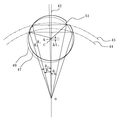
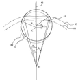
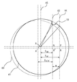
ここで円盤の半径を求める原理を、図12を用いて、円盤円周と3つのセンサの旋回軌道とを交叉させた場合について説明する。旋回基線40は、予め定めたものである。3本の検出軌道43,44,45のうち43が切り欠き部を通ったとすると、他の検出軌道44および検出軌道45のウエハ外周縁との交点2つずつのそれぞれの間の線分の垂直二等分線42は共通で、旋回基線40とのなす角度はα1 であるが、検出軌道43の場合の垂直二等分線48と旋回基線40とのなす角度はα2 で、先のα1 と異なっている。従って、一つだけ垂直二等分線の角度が異なる検出軌道43を除外する。
検出軌道44および検出軌道45のウエハ外周縁との交点2つずつのそれぞれと旋回中心Oとからなる三角形はともに二等辺三角形で、線42は直角三角形を4つ作っている。旋回角度θ1 、θ2 はともに測定角、旋回半径R1 、R2 はともに設定距離、Lは未知数である。
r2 =(R1cosθ1 −L)2+R1 2sin2θ1 ・・・(式21)
r2 =(R2cosθ2 −L)2+R2 2sin2θ2 ・・・(式22)
旋回中心からみて検出軌道44と45が円盤中心より遠い距離にある場合、
L=R1cosθ1 −(r2 −R1 2sin2θ1)1/2 ・・・(式23)
L=R2cosθ2 −(r2 −R2 2sin2θ2)1/2 ・・・(式24)
式21に式24を代入すると、
【数3】
ここで、
S=(r2 −R2 2sin2θ2)1/2 ・・・(式26)
とおき、式25に式26を代入すると、
【数4】
【数5】
【数6】
【数7】
ちなみに、半径未知の円盤状物の半径rは、正の数だから、(式33)で求められる。
【数8】
【0038】
請求項2,5,14および請求項8,11,16は、前述の原理を応用した教示方法や位置決め方法および教示装置や位置決め装置のうち、センサ軌跡が円軌道である新規な方法および装置に限定している。この円軌道上をセンサが運動してもよいし、円盤状物が旋回運動してもよい。
さらに、本発明は請求項18において、前記のような教示装置、位置決め装置および搬送装置のいずれか1つ又は複数を用いることによって、改善された半導体製造設備を提供する。
本発明は、位置決め専用装置においても、搬送装置においても実現できる。また、ここで言う搬送装置は、旋回運動機構および/又は直線運動機構をもつ搬送装置、例えば、スカラ型ロボット、多関節ロボット、XY軸移動テーブル等公知の装置を含む。
【0039】
前記円盤状物の外周上の2点を検知するセンサの種類としては、非接触型のセンサを用いることが好ましい。電子部品である半導体ウエハを取り扱うことが多いため、電磁気的センサや機械的センサではなく、透過型または反射型の光センサーが好ましく、その中で、画像処理手段を伴うCCD等の二次元センサであっても、光量が定量化されるラインセンサであっても、ON、OFFが分る点センサであってもよい。この光センサは本発明を実現するためには、最小限点センサ1個で充分であるが、前述の如くノッチやオリエンテーションフラットを検出させるために2個のセンサを用いてもよい。偏移角を測定するセンサとしては、エンコーダなど公知の角度センサを用いてもよいが、サーボモータやステッピングモータ等のパルスモータにより角度としてのパルス値を採用してもよい。
本発明において記述した上記各計算式は、通常のコンピュータプログラムにより、搬送装置の搬送ロボットの制御用等のコンピュータで構成する算出手段で容易にその計算を実行でき、その計算結果は、搬送装置のロボット等の制御用のコンピュータで構成する制御手段に用いれば、容易に搬送装置の各部の運動軌道に反映することができる。
また、本発明における基準座標系は、直角座標系だけでなく極座標系であってもよく、またその座標系での位置を座標値で直接的に表されるものだけでなく搬送ロボットの各軸の作動量等で間接的に表されるものでもよい。
【0040】
【発明の実施の形態】
以下に、本発明に係る半導体製造設備について、円盤状物を位置決めする方法の実施例を図面に基づいて説明する。
図1に示す半導体製造設備1は、円盤状物であるウエハ13をカセット6からロードロック室8等へ搬送する搬送装置2と、ロードロック室8に接続してウエハ13に対し成膜、拡散、エッチング等の各種処理を行う処理装置3とを具えてなる。そのうちの搬送装置2は、ウエハが棚段状に収納されるカセット6を載置できる1個又は複数個のステージ19と、搬送アーム12を有するスカラ型の搬送ロボット4と、その搬送ロボット4を並んでいる複数個のステージの前でその列に平行に動かす移動手段17と、検出手段としてのセンサ9と、それら搬送ロボット4と移動手段17とセンサ9との作動を制御する、通常のコンピュータを有する制御部11とを具えて構成されている。なお、円盤状物の正確な位置補正を行なったり、ウエハ縁部のノッチ等切り欠き部を検出するために、図25に示す如き従来の位置決め装置10を搬送装置2の構成に含めることもできる。
【0041】
同じく図1に示す処理装置3は、レジスト塗布、露光、エッチング等各種処理を行う1個ないし複数個のチャンバ7と、前記チャンバ7同士をつなぐ移載室16と、移載室16内に備えられ円盤状物を搬送する真空ロボット31と、検出手段であるセンサ9と、搬送装置2のスカラ型搬送ロボット4により搬送された円盤状物の受け渡しを行うロードロック室8と、それらチャンバ7と真空ロボット31とセンサ9とロードロック室8の後述するドアとの作動を制御する、搬送装置2と共用の制御部11とを具えて構成されている。
なお、ロードロック室8には、複数枚の円盤状物を棚段上に載置するための図示しないポケットを設けてある。また、ロードロック室8内を真空状態とするため、搬入出口にはロードロックドア32が配設されている。
【0042】
〔基準位置教示方法(1)〕
各カセット、各ロードロック室、各処理チャンバなど各ポートでの教示を行う前にまず保持部と円盤状物との位置関係を示す原点座標を教示する。
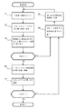
図2の半導体製造設備1内でウエハ13を自動搬送させるには、事前に、搬送装置2と処理装置3との制御部11に、搬送ロボット4および真空ロボット31の少なくとも一方の位置を含む基準座標系上で原点座標とする基準位置を教示した後に、搬送軌道を教示する必要がある。教示前の位置は通常余裕を含めて設計されているので、詳細は現場合わせが必要である。本発明の基準位置教示方法の一実施例を、一つのロードロック室8を用いる場合について、図13のフローチャートに示す。
【0043】
先ずステップS11で、教示前の設計上の、上記基準座標系での第1ロードロック室8の仮位置情報(初期値)を制御部11に入力する。次いでステップS12で、搬送ロボット4の保持部14をロードロックドア32経由で導入して、その保持部14で、第1ロードロック室8内の、基準位置とする所定場所に手作業で置いたウエハまたはそれと同一直径の他の板からなる円盤状物(ここではウエハと同一符号で示す)13を保持し搬出する。
次いでステップS13で、搬送ロボット4が、保持した円盤状物13を検知手段としてのセンサ9のところに搬送し、ロボット4の胴体軸を中心に旋回して、センサ9の光で円盤状物13の外周縁部を円弧に切ってその円盤状物13の外周縁とセンサ光との交点の2点の、保持部14に対する位置ひいては上記基準座標系での位置を検出する。そしてステップS14で、得られた外周縁上の2点の位置情報から先に述べた計算式で求めた、上記所定場所での円盤状物13の中心位置を、基準位置として、制御部11の持つ搬送ロボット作動制御プログラムへ伝達し、ステップS11で入力した仮位置情報を書きかえ、原点座標教示作業を終了する。
ちなみに、これらステップS11〜S14は、制御部11に予め与えられたプログラムにより、制御部11自身が実行する。
【0044】
同様にして、真空ロボット31を用いて他のロードロック室8など各ポートについてそれぞれ教示する。即ち、本発明では、各ポートに関し最初に手動で基準位置とする所定場所にウエハなど基準円盤を置く以外は、すべて自動教示(オートティーチング)することができる。その際、保持部14が円盤状物13を保持する時に保持部14の保持中心と円盤状物13の中心とが従来の教示方法のように完全一致する必要はなく、搬送ロボット4のアームがロードロックドア32や他の機器に干渉しない程度なら多少ずれていてもよい。
【0045】
〔基準位置教示方法(2)〕
本発明の基準位置の教示方法の他の実施例においては、従来の案内治具を使用してもよい。保持部14を人が作業し易い適当な位置に移動させて、図3に示す如き案内治具20を保持部14に設置し、円盤状物を保持部14上に載置してその案内治具20に手で押し当て、その時の円盤状物の中心位置を基準位置とする方法である。この案内治具20は、ウエハと合致する曲面と、保持部14からなる平面の基準面を以って、物理的にウエハの位置を固定するものである。図14は、図3の装置においてオートティーチング(自動教示)を実施するときの処理手順のフローチャートを示しており、この処理では、各カセット、各ロードロック室など各ポートでの教示を行う前に、先ず保持部と円盤状物との位置関係を基準位置として教示する。
【0046】
先ずステップT1で、保持部14に対する円盤状物の仮位置情報(初期値)を制御部11に入力する。次いでステップT2で、保持部14上に案内治具20と円盤状物13とを手作業で載置し、円盤状物の中心位置が適正な位置に来るように手作業で調整する。
次いでステップT3で、検知手段としてのセンサ9のところで円盤状物13を旋回運動させて、円盤状物13の外周縁とセンサ光との交点の2点の、保持部14に対する位置ひいては上記基準座標系での位置を検出する。そしてステップT4で、得られた位置情報から先に述べた計算式で求めた保持部14上での円盤状物13の中心位置を、保持部14上の基準位置として、制御部11の持つ搬送ロボット作動制御プログラムへ伝達し、制御部11に記憶させる。
ちなみに、これらステップT1〜T4は、ステップT2を除き、制御部11に予め与えられたプログラムにより、制御部11自身が実行する。
【0047】
〔その他のポートの教示方法〕
前述のように定めた基準位置を基に、オートティーチングにより円盤状物をカセットから搬出する場合の教示(位置決めおよび軌道修正を含む)の手順について、図15のフローチャートに示す。
【0048】
先ずステップU1で、搬送仮位置情報(初期値)および基準位置情報を制御部11に入力する。次いでステップU2で、カセット6および円盤状物13を手作業で設計上の位置へ載置する。
次いでステップU3で、搬送ロボット4がカセット6内の受け渡し場所から円盤状物13を受け取る。そしてステップU4で、搬送ロボット4が円盤状物13をセンサ9のところに移動させて旋回させ、上記と同様に外周縁の2点を検出する。
次いでステップU5で、ステップT4で得られた情報(測定値)を偏移量算出手段へ伝達する。次いでステップT6で、偏移量算出手段により測定値と基準位置を比較し偏移量を算出する。次いでステップU7で、ずれている場合、偏移量を制御部11の持つ搬送ロボット作動制御プログラムへ伝達する。
ちなみに、これらステップU1〜U7は、ステップU2を除き、制御部11に予め与えられたプログラムにより、制御部11自身が偏移量算出手段等となって実行する。
そしてステップU8で、制御部11は、上記偏移量を考慮して搬送ロボット4の軌道を修正する。つまりは設計図面上の搬送位置である初期値を更新する。ずれていなければ一連の教示は終了する。
【0049】
同様に、他のカセット6、各ロードロック室8など各ポートとの受け渡し場所についても、それぞれ図15のステップU1からステップU8までの手順に沿って行われる。本発明に基づく教示方法によって、ステップU2における円盤状物を手作業で設計図面上の位置へ載置する工程以外は、全て自動的に行うことができるようになった。
【0050】
また、メンテナンス時にカセット6等の位置を移動させた場合、従来は図26の手間の掛かるステップS1からS7まで工程を全て手動で再度行っていたが、本発明に基づくオートティーチングでは、図15のステップU2のみ手動で行えば、後は自動的に進む。また、保持部14を取り替えた場合は、基準位置の教示をステップU1から再び行い、新旧の情報を比べ、偏移量をそれぞれの測定値に反映させればよい。これにより、ロードロック室8への搬送位置は常に一定となり、各処理チャンバ7付近での干渉がなくなり、ごみも軽減される。
【0051】
図16は、本発明の円盤状物の位置決め装置の一実施例としての、搬送ロボット4と、検出手段である光学式点センサ9とを備えた搬送装置2を示す。この搬送ロボット4の搬送アーム12を動作させる駆動手段は、あらかじめ設定された基準点を持ち、偏移量は光学センサ9の出力信号と上記駆動手段のステッピングモータのパルスとを計測し演算して求める。搬送アーム12が始動する際、搬送ロボット4の全軸が基準点にあることを制御部11により確認し、制御部11からの命令により、搬送ロボット4の各軸を屈伸、昇降動作させ、センサ9のところで旋回させ、ウエハ13の位置決めを実施する。
【0052】
図16はまた、ウエハ13の基準位置が予め教示されている本発明の位置決め方法の一実施例を説明したものである。ウエハ13をカセット6から搬送アーム12の保持部14上に載置して搬出した搬送ロボット4は、その胴体の回転軸を中心に旋回して、検出手段としての固定された光学センサ9のコの字状枠の間にウエハ13を通過させ、ウエハ13の外周縁部をセンサ光で円弧に切る。これによってウエハ13の中心位置が計測算出され、偏移量とウエハ外周縁の位置座標とが上記偏移量算出手段により算出されて、搬送アーム12の保持部14上におけるウエハ位置が決まる。
【0053】
算出された偏移量は、搬送アーム12の動作を制御している制御部11に送られ、予め教示された搬送位置の情報に、偏移量を考慮した補正値を加えることにより、搬送位置および搬送軌道が修正される。また、図16中の検知手段としてのセンサ9は、ウエハ13を保持した搬送アーム12が旋回動作するとき、搬送ロボット4に対し定められた位置で、且つ、円盤状物13を検知することができる位置に設置される。
図16の右側の処理装置3内の真空ロボット31も、同様にして検出手段としてのセンサを用いて、各ロードロック室8、各処理チャンバ7における基準位置の教示、ウエハ13を受け取った後の位置補正のための位置決めを実施するものである。
【0054】
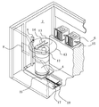
〔位置決め装置(アライナ)に採用した場合1〕
図17は、本発明の位置決め方法を位置決め装置に用いた一実施例について示すものである。この位置決め装置10はウエハ13を真空吸着できる保持台19を備え、保持台19の下方には回転手段と1軸ないしは2軸方向へ移動可能にするX軸移動手段、Y軸移動手段と、昇降手段21を備えている。ここでは、搬送ロボット4等により載置されたウエハ13が静置された状態で、ステージ上に設けられた検出アーム24が旋回して検出軌跡43を描き、検出アーム24の先端部に設けられた検出手段としての光学式センサ9によりウエハ13の外周縁上の2点が検出される。この2点の位置を用い、前述した本発明の計算方法を適用してウエハ中心を算出し、X,Y軸方向の修正を行い、持ち替えて正常位置におかれたウエハを回転させ、別のセンサがそのウエハ13の縁部にある切り欠き部を検出し回転を停止する。
【0055】
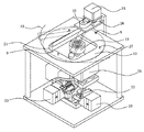
〔位置決め装置(アライナ)に採用した場合2〕
図18は、検出アーム24がウエハ半径より短い場合についての位置決め装置10を示し、動作方法および位置決め方法は図17と同様である。
【0056】
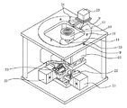
〔位置決め装置(アライナ)に採用した場合3〕
図19は、従来の位置決め装置で本発明の位置検出方法を実施する場合について示したものである。この位置決め装置10は、回転しうる保持台19とX軸移動手段およびY軸移動手段と昇降手段と検知手段としての点センサ9とを備えている。回転するウエハ13が偏芯している場合は、回転によりウエハ13と同じ半径の検出軌道43で、ウエハ縁部が切られ2点を検出する。それ以降の位置決め方法は図17の装置と同様である。
【0057】
従来、搬送ロボット等により載置台に搬送された円盤状物は、光学式のラインセンサを用いる特開平6−224285で示される検出方法等で円盤状物の中心位置情報が得られる。この方法では載置部を回転駆動させ、1周分の縁部の位置情報を検知する必要があり、図20に示すように縁部の一部がラインセンサの検出範囲外にある場合については、X軸、Y軸の移動手段を駆動させ検出範囲内に入るように円盤状物を持ち替えることを前提に位置決め動作を行っている。そこで、本発明の位置決め方法を用いると、縁部の一部が検出範囲外に出ていても、ウエハの回転により必ず他の部分がセンサに入るので、ラインセンサ上の1点を検出点として定めておけば、図19と同様、本発明の中心位置算出方法により円盤状物の中心位置情報が算出される。即ち、持ち替えは全く不要でウエハの中心を算出することができる。
なお、ウエハの中心位置が分れば、位置決め装置のX,Y駆動部は不要で、図21に示すように、搬送ロボット4を動作させることにより、載置前に保持部14を正常位置に移動させて円盤状物13の位置決めをすることができる。
【0058】
〔保持部にセンサ〕
図22に示すように、搬送ロボット4の保持部14の先端ないし側部にセンサ9を設けて、搬送ロボット4の旋回や屈伸動作により、載置された円盤状物13の外周縁の2点を検出し、円盤状物13の中心位置を算出することができる。なお、検出軌道上に切り欠き部等が重なるか否かの判別をする場合、図10、図11に示した方法により、保持部14に2つの検出手段を配設するか、1つの検出手段で円盤状物13を2回走査させればよい。
【0059】
〔ポートドアにセンサ〕
図23は、搬送装置2のカセット用ドアにセンサ9を2個を取り付け(図では片方のみ示す)、搬送ロボット4の搬送アーム12を駆動して直線運動させ、ウエハ13を取り出す際、その中心を算出して位置決めし、搬送すべき他のポートへの正しい軌道に修正する。計算方法は図10、図11に示した通りである。
【0060】
〔直線運動〕
図24は、請求項9記載の本発明の位置決め装置の一実施例である。搬送ロボット4に付属させてセンサ1個からなる検出手段9を設け、搬送ロボット4の搬送アーム12を駆動してウエハ13を直線運動させ、ウエハ13の外周縁上の2点を検出する。これらによって中心を算出して位置決めし、搬送すべき他のポートへの正しい軌道に修正する。計算方法は先に(式12)から(式15)に示した通りである。
なお、本発明の教示方法や位置決め方法や搬送方法を実施するための位置計算等は、上記実施例では搬送装置2の制御部11が行ったが、本発明はこれに限られず、上記制御部11に接続した別途のコンピュータ等が行ってもよい。
また、図13のステップS11と、図14のステップT1と、図15のステップU1とでの初期値の入力は、上記実施例ではプログラムの実行により自動的に行っているが、キーボード操作等で人手で行ってもよい。
【0061】
【発明の効果】
以上説明したように、本発明の円盤状物の基準位置教示方法および位置決め方法により、位置決め専用機を特に必要しないので、省スペース化が図れ、装置コストも押さえることができる。また、検出手段であるセンサも1個又は2個の安価な点センサで充分であり、コスト低下に貢献できた。
【0062】
さらに、本発明を基にした自動教示により、図1の半導体製造設備の場合、作業工数が大幅に短縮でき、作業時間も従来の約10分の1の1〜2時間程度に短縮することができた。さらに、搬送位置の目視確認等の人為的な誤差がなくなったので、メンテナンスを行っても作業前の状態に容易に回復できる。また円盤状物の搬送中に偏移量を算出することができるため、位置決め装置へ搬送する往復時間が省かれ、生産性も向上した。そして検出手段を常時作動させておき必要に応じて検出手段9を通過させれば、位置ずれ検出が行われるため、搬送が正常に行われているかを管理し、常に正常運転させることができる。
【0063】
加えて、未知の円盤状物の半径も測定、判別することができるため、枚葉毎に本発明の装置で半径を確認すれば、サイズが異なるウエハを同時に半導体処理装置に供給して処理することができ、ライン稼働率と生産性の向上を実現することができる。
【図面の簡単な説明】
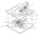
【図1】本発明を実施するための半導体製造設備の一実施例を示す一部切り欠き斜視図である。
【図2】上記実施例の半導体製造設備を示す平面図である。
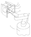
【図3】上記実施例の半導体製造設備における搬送ロボットを示す一部切り欠き斜視図である。
【図4】本発明の方法の原理を示す平面図である。
【図5】本発明の方法の原理を示す他の平面図である。
【図6】本発明の方法の2個の検出手段による切り欠き部検出原理を示す平面図である。
【図7】本発明の方法の2個の検出手段による切り欠き部検出原理を示す他の平面図である。
【図8】本発明の方法の1個の検出手段による切り欠き部検出原理を示す平面図である。
【図9】本発明の方法の1個の検出手段による切り欠き部検出原理を示す他の平面図である。
【図10】本発明の方法の2個の検出手段による切り欠き部検出と位置決めの原理を示す平面図である。
【図11】本発明の方法の2個の検出手段による切り欠き部検出と位置決めの原理を示す他の平面図である。
【図12】本発明の方法に基づく円盤半径の算出原理を示す平面図である。
【図13】本発明の教示方法の一実施例を用いた搬送装置への教示手順を示すフローチャートである。
【図14】本発明の教示方法の一実施例を用いた搬送装置への教示手順を示すフローチャートである。
【図15】本発明の位置決め方法の一実施例を用いた搬送装置へのその他のポートの教示手順を示すフローチャートである。
【図16】本発明を実施するための搬送装置の一実施例を示す一部切り欠き斜視図である。
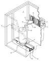
【図17】本発明を実施するための位置決め装置の一実施例を示す一部切り欠き斜視図である。
【図18】本発明を実施するための位置決め装置の他の一実施例を示す一部切り欠き斜視図である。
【図19】本発明を実施するための位置決め装置の他の一実施例を示す一部切り欠き斜視図である。
【図20】本発明を実施するための位置決め装置の他の一実施例を示す一部切り欠き斜視図である。
【図21】本発明を実施するための位置決め装置の他の一実施例を示す一部切り欠き斜視図である。
【図22】本発明の1個の検出手段による切り欠き部検出と位置決めの一実施例を示す一部切り欠き斜視図である。
【図23】本発明の2個の検出手段による切り欠き部検出と位置決めの一実施例を示す一部切り欠き斜視図である。
【図24】本発明を実施するための搬送装置の一実施例を示す一部切り欠き斜視図である。
【図25】従来の搬送装置を示す一部切り欠き斜視図である。
【図26】従来の搬送装置における教示手順を示すフローチャートである。
【図27】従来の位置決め装置の例を示す斜視図である。
【符号の説明】
1 半導体製造設備
2 搬送装置
3 処理装置
4 搬送ロボット
5 ロードポート
6 カセット
7 処理チャンバ
8 ロードロック室
9 検出手段(センサ)
10 位置決め装置
11 制御部
12 搬送アーム
13 円盤状物(ウエハ)
14 保持部
15 カセット載置台
16 移載室
17 直線移動手段
18 ネジ軸
19 保持台
20 案内治具
21 昇降手段
22 ネジ軸
23 モータ
24 検出アーム
25 プーリ
26 タイミングベルト
27 ウエハ載置台
31 真空ロボット
32 ロードロックドア
40 旋回基線
41 旋回中心から基準円盤状物の中心へ向かう直線
42 旋回中心から円盤状物の中心へ向かう直線
43 検出軌道
44 43と異なる検出軌道
45 44と異なる検出軌道
46 基準となる円盤状物
47 測定しようとする円盤状物
48 凹部を検出した際の垂直二等分線
49 仮想の円盤状物
50 47と異なる旋回半径上にある円盤状物
51 切り欠き部(ノッチ)[0001]
BACKGROUND OF THE INVENTION
The present invention must be performed when handling a disk-shaped object such as a semiconductor wafer between a plurality of locations, and is a reference position that serves as a reference for the position of the disk-shaped object in the reference coordinate system including the position of the handling device. A positioning method and apparatus using the method for determining the center position in the teaching, and a transport method and apparatus for automatically correcting the transport trajectory using the positioning, and further, The present invention also relates to a semiconductor manufacturing facility using the above apparatus.
[0002]
[Prior art]
As shown in FIGS. 1 and 2, in general, the semiconductor manufacturing facility 1 moves from a
[0003]
FIG. 26 shows a part of a flowchart of a teaching (teaching) process in the
[0004]
For example, when teaching about the process of transporting a disk-shaped object such as the
[0005]
Next, in step S3, as shown in FIG. 3, a
[0006]
If there is no deviation in the confirmation in step S3, in step S6, the held disk-like object is transferred to the delivery position with the
[0007]
Hereinafter, with respect to the
[0008]
Further, in the conventional production process, the disk-shaped object is positioned each time by using a positioning device (dedicated machine) 10 as shown in FIG. In the
[0009]
In Japanese Examined Patent Publication No. 7-27953, in order to improve the productivity by omitting the transfer step, the transfer arm of the transfer robot is operated while holding the wafer, and each of the
[00010]
[Problems to be solved by the invention]
However, in the conventional teaching work described above, as shown in the flowchart of FIG. 26, trial and error is performed with all the equipments involved in the
[0011]
Further, as described above, a portal type positioning apparatus described in Japanese Patent Publication No. 7-275953 shown in FIG. 27 has been proposed for positioning a disk-shaped object during production. Since the method is used, there is no change in the labor required for starting up the equipment. In addition, since it is a device that passes through a gate, there is a problem that one device must be installed at each load lock chamber or each entrance of each processing chamber, and this device is larger than the diameter of a disk-shaped specimen such as a wafer. There was a problem that the investment amount was large because it was a device. Furthermore, since there is no positioning step before inserting the disk-shaped object into the portal type positioning device, it is necessary to perform manual positioning that takes time and effort as described above so that the disk-shaped object does not collide with the device. was there. In the event of a collision, the generation of dust is indispensable, and there is also a problem that it may lead to damage of the test object such as a wafer.
[0012]
Further, in the positioning method described in the above Japanese Patent Publication No. 7-27953, the method of discriminating the notch is illustrated geometrically, but no method of algebraically discriminating has been found. Therefore, in order to take the method of calculating the center of the disk by the least square method which is an approximate expression method, at least three
[0013]
[Means for Solving the Problems]
As a result of intensive investigations to solve these problems, the present invention has developed a new and rigorous calculation method to measure and calculate the amount of deviation of the center position of a disk-like object such as a wafer, The present invention proposes a new automatic teaching method (auto teaching) and positioning method that realize quick start-up. The present invention also proposes a teaching device based on this theory, a positioning device, a transport method for correcting a transport trajectory based on the calculated deviation amount, a transport device, and semiconductor equipment using these. By the way, “teaching” as used in the present invention is a standard that includes the position of the handling device at the place where the disk-like material is placed, which is the standard for the operation of the holding unit of the handling device that carries the disk-like material and other handling. The reference position, which is the position coordinate in the coordinate system, is to be input and stored in the handling device, and “positioning” in the present invention is a disk-like shape placed at an arbitrary position on the holding unit or the like. This refers to finding out how much the position of the object and the holding part for holding it deviates from the previously inputted reference position.
[0014]
First, the principle of the present invention will be described. FIG. 4 shows a case where the circumference of the disk intersects with the arc-shaped trajectory of one sensor. The
[0015]
Next, as a center position of the
△ W1 From BO, BO = Rcos θ, W1 B = Rsin θ (Formula 1)
△ W1 From BA, BO = rcos φ + L1 , W1 B = rsin φ (Formula 2)
That is, Rcos θ = rcos φ + L1 ... (Formula 3)
Rsin θ = rsin φ (Equation 4)
When rearranged, rcos φ = Rcos θ-L1 ... (Formula 5)
rsin φ = Rsin θ (Equation 6)
When (Equation 5) and (Equation 6) are squared and both left and right sides are added,
cos2φ + sin2Because φ = 1
r2 = (Rcos θ-L1)2 + R2sin2 θ (Equation 7)
Therefore, L1 = Rcos θ ± (r2 -R2sin2 θ)1/2 .... (Formula 8)
[0016]
Here, as shown in FIG. 4, when the center A of the disk to be measured with respect to the
L1 = Rcos θ- (r2 -R2sin2 θ)1/2 .... (Formula 9)
If it ’s on the outside,
L1 = Rcos θ + (r2 -R2sin2 θ)1/2 ... (Formula 10)
It becomes.
Here, since the center position C of the previously taught
Diameter deviation length ΔH = L1 -L0 .... (Formula 11)
Therefore, the disk can be positioned by using the previous shift angle α and the shift length ΔH in the diameter direction according to (Equation 11).
[0017]
Next, referring to FIG. 5, a case will be described in which the
[0018]
Similarly, in FIG. 5, a case will be described in which the circumference of a disk-
△ ABW2 Is a right triangle,
X1 2+ (BW2)2 = R2 .... (Formula 12)
Where BW2 = W1 W2 / 2, so
X1 = ± {r2 -(W1 W2 / 2)2}1/2 (Equation 13)
Therefore, the amount of deviation in the X direction is
ΔX = X0 -X1 .... (Formula 14)
Is calculated as
[0019]
Here, the point D on the
Therefore, the amount of deviation in the Y direction
ΔY = BD (Equation 15)
Is also determined by measurement.
Therefore, the shift amount (ΔX, ΔY) is calculated.
[0020]
The invention according to claim 1 and
[0021]
The specific point here is defined as a point that is known or determined by measurement. That is, when the locus of the detecting means is a circle, it is the turning center of this circle, which is known. If the locus of the detection means is a straight line, it can be obtained immediately by measurement at the midpoint of the line connecting the two intersections with the circumference. In this teaching method, when placing a disk-like object at a predetermined place as a reference position, it is preferably performed manually, and when using a commercially available wafer as the disk-like object, preferably a notch, an orientation flat, etc. The recess is placed away from the detection trajectory. Moreover, you may use the disk shaped object which does not have a recessed part and a convex part other than a wafer. Note that the position of the convex portion or the concave portion may be automatically recognized by image processing or the like, and the convex portion or the concave portion may be automatically placed away from the detection trajectory.
[0022]
Similarly, according to the above-described principle, when the disk-like object has no recesses or protrusions, or when these are avoided as described above, the positioning of the disk-like object according to
In the present invention, a sensor for detecting a disk-shaped object may be fixed and the disk-shaped object may move, or the disk-shaped object may be fixed and the sensor may move. This motion may be a linear motion or a circular motion.
Further, in the methods of
[0023]
[Method 1 for avoiding the notch]
The invention according to
[0024]
More specifically, when both of the detection tracks 43 and 44 do not pass through the notch, the center A of the disk is obtained from the two triangles on the left side of the
[Expression 1]
[Expression 2]
[0025]
In FIG. 7, when there is a notch in the
That is, if the detected trajectory passes over the notch, the calculated disk center is always near the turning center O and is calculated to be small. In both cases, the two detection tracks are separated so that the notch does not enter, the circumference of the disk is cut into two arcs, and both ends are measured. That is, the one with the larger distance AO value may be selected.
Incidentally, when there is no notch on the two
[0026]
[
Next, as shown in FIGS. 8 and 9, two different arcs may be formed by one sensor and two swiveling operations. That is, when calculating the center of the disk-like object, the distance R from the turning center O to the
[0027]
First, the detection procedure will be described with respect to the case where the
AO = Rcos θ1 -(R2 -R2sin2 θ1)1/2 (Equation 18)
On the other hand, when the
CO = Rcos θ2 -(R2 -R2sin2 θ2)1/2 ... (Formula 19)
AO-CO = ΔL1 .... (Formula 20)
That is, when it hits the notch, the center C becomes ΔL1 It is calculated that only the turning center O side is approached.
[0028]
Next, as shown in FIG. 9, a case where the second turning operation is performed by shifting the distance m will be described. When the
Therefore, CO (= A ′ O−ΔL1 ) And A "Om, the larger one (A" Om) may be adopted.
Similarly, if the notch portion is not found in the first turning operation, but the second turning operation is found, the larger one may be selected as the distance between the correct center of the disk and the turning center.
[0029]
Next, when there is a convex part (not shown) on the circumference of the disk, it is always larger than the line segment formed by the two intersections as compared with the case where there is no convex part. Therefore, when there is a convex part on the circumference of the disk, it is calculated that the center of the disk is always farther from the turning center than when there is no protrusion. In other words, among the distances calculated from the two line segments according to
If the concave portion or the convex portion is not on the two detection trajectories, either one may be adopted to find the center position at the same place as described above.
[0030]
Further, in the fourth and tenth aspects, the same can be said for the case where the two
[0031]
More specifically, in FIG. 10, if both the
However, when the
Therefore, XAP<XA'Q XAB+ M <XA'Q It becomes.
That is, the center position information based on the detection results in the
[0032]
Similarly, FIG. 11 shows a case where the
If there is a notch on the
Therefore, the center position information in the detection results of the
[0033]
Further, claims 4 and 10 include a case where two different circular arcs are formed by one linear motion with one sensor. That is, in FIG. 10 and FIG. 11, if the trajectory of the detection means 9 draws the
Next, in
[0034]
[Method for Determining Wafer Radius r Using Three Detection Trajectories]
Of the disk-shaped products, six types of semiconductor wafers, 3 inch, 4 inch, 5 inch, 6 inch, 8 inch, and 300 mm, are defined by the SEMI standard by the International Semiconductor Manufacturing Equipment Material Association, and their radii are also standardized. In addition, each size is stored in a dedicated cassette. Therefore, since the radius r of the wafer is known when the cassette is placed, it has been treated as a known value in the above calculation process. However, when checking which wafer size during the transfer process, there is a case where it is desired to measure the radius due to a difference in wafer diameter by a manufacturer or variation between lots. In the present invention, in response to such a requirement, the radius r of the disk-shaped object can also be measured and calculated.
[0035]
[0036]
Here, the principle of obtaining the radius of the disk will be described with reference to FIG. 12 in the case of intersecting the disk circumference and the turning trajectories of the three sensors. The turning
The triangle formed by each of the two intersections of the
r2 = (R1cosθ1 -L)2+ R1 2sin2θ1 ... (Formula 21)
r2 = (R2cosθ2 -L)2+ R2 2sin2θ2 ... (Formula 22)
When the detection tracks 44 and 45 are at a distance from the center of the disk when viewed from the turning center,
L = R1cosθ1 -(R2 -R1 2sin2θ1)1/2 ... (Formula 23)
L = R2cosθ2 -(R2 -R2 2sin2θ2)1/2 ... (Formula 24)
Substituting
[Equation 3]
here,
S = (r2 -R2 2sin2θ2)1/2 ... (Formula 26)
When substituting
[Expression 4]
[Equation 5]
[Formula 6]
[Expression 7]
Incidentally, since the radius r of the disk-shaped object whose radius is unknown is a positive number, it can be obtained by (Expression 33).
[Equation 8]
[0038]
Furthermore, the present invention provides, in
The present invention can be realized in both a positioning apparatus and a transport apparatus. Further, the transfer device referred to here includes a known device such as a transfer device having a turning motion mechanism and / or a linear motion mechanism, such as a SCARA robot, an articulated robot, or an XY axis movement table.
[0039]
As a type of sensor for detecting two points on the outer periphery of the disk-like object, it is preferable to use a non-contact type sensor. Since a semiconductor wafer, which is an electronic component, is often handled, a transmissive or reflective optical sensor is preferable instead of an electromagnetic sensor or a mechanical sensor. Among them, a two-dimensional sensor such as a CCD with image processing means is used. Even if it is, it may be a line sensor in which the light quantity is quantified, or it may be a point sensor that shows ON and OFF. In order to realize the present invention, a single point sensor is sufficient as the optical sensor. However, as described above, two sensors may be used to detect notches and orientation flats. As the sensor for measuring the deviation angle, a known angle sensor such as an encoder may be used, but a pulse value as an angle may be employed by a pulse motor such as a servo motor or a stepping motor.
The above-described calculation formulas described in the present invention can be easily executed by calculation means configured by a computer for controlling the transfer robot of the transfer apparatus, etc., by a normal computer program. If it is used as a control means composed of a control computer such as a robot, it can be easily reflected in the motion trajectory of each part of the transport apparatus.
Further, the reference coordinate system in the present invention may be not only a rectangular coordinate system but also a polar coordinate system, and the position in the coordinate system is not only directly expressed by coordinate values, but also each axis of the transport robot. It may be expressed indirectly by the amount of operation.
[0040]
DETAILED DESCRIPTION OF THE INVENTION
Embodiments of a method for positioning a disk-like object will be described below with reference to the drawings for semiconductor manufacturing equipment according to the present invention.
The semiconductor manufacturing facility 1 shown in FIG. 1 has a
[0041]
Similarly, the
The
[0042]
[Reference position teaching method (1)]
Before teaching at each port such as each cassette, each load lock chamber, each processing chamber, etc., first, the origin coordinates indicating the positional relationship between the holding portion and the disk-like object are taught.
In order to automatically transfer the
[0043]
First, in step S11, the temporary position information (initial value) of the first
Next, in step S13, the
Incidentally, these steps S11 to S14 are executed by the
[0044]
Similarly, each port such as another
[0045]
[Reference position teaching method (2)]
In another embodiment of the reference position teaching method of the present invention, a conventional guide jig may be used. The holding
[0046]
First, in step T <b> 1, temporary position information (initial value) of the disk-shaped object with respect to the holding
Next, in step T3, the disk-
Incidentally, these steps T1 to T4 are executed by the
[0047]
[Other port teaching methods]
The flowchart of FIG. 15 shows the procedure of teaching (including positioning and trajectory correction) when a disc-shaped object is carried out from the cassette by auto teaching based on the reference position determined as described above.
[0048]
First, in step U1, the transport temporary position information (initial value) and the reference position information are input to the
Next, at step U3, the
Next, in step U5, the information (measured value) obtained in step T4 is transmitted to the deviation amount calculating means. Next, in step T6, the deviation amount is calculated by comparing the measurement value with the reference position. Next, in step U7, when there is a deviation, the deviation amount is transmitted to the transfer robot operation control program of the
Incidentally, these steps U1 to U7 are executed by the
In step U8, the
[0049]
Similarly, the delivery location with each port such as another
[0050]
Further, when the position of the
[0051]
FIG. 16 shows a
[0052]
FIG. 16 also illustrates an embodiment of the positioning method of the present invention in which the reference position of the
[0053]
The calculated deviation amount is sent to the
Similarly, the
[0054]
[When used in a positioning device (aligner) 1]
FIG. 17 shows an embodiment in which the positioning method of the present invention is used in a positioning device. The
[0055]
[When used in a positioning device (aligner) 2]
FIG. 18 shows the
[0056]
[When used in a positioning device (aligner) 3]
FIG. 19 shows a case where the position detection method of the present invention is carried out with a conventional positioning device. The
[0057]
Conventionally, a disk-shaped object conveyed to a mounting table by a conveying robot or the like can obtain center position information of the disk-shaped object by a detection method shown in JP-A-6-224285 using an optical line sensor. In this method, it is necessary to detect the position information of the edge part for one rotation by rotating the mounting part. As shown in FIG. 20, when the part of the edge part is outside the detection range of the line sensor. The positioning operation is performed on the premise that the disc-shaped object is moved so as to be within the detection range by driving the moving means of the X axis and the Y axis. Therefore, when the positioning method of the present invention is used, even if a part of the edge is out of the detection range, the other part always enters the sensor due to the rotation of the wafer, so one point on the line sensor is used as the detection point. If determined, the center position information of the disk-like object is calculated by the center position calculation method of the present invention as in FIG. In other words, the center of the wafer can be calculated without having to change the wafer at all.
If the center position of the wafer is known, the X and Y driving units of the positioning device are not necessary, and the holding
[0058]
[Sensor in the holding part]
As shown in FIG. 22, the
[0059]
[Sensor on port door]
FIG. 23 shows two
[0060]
[Linear motion]
FIG. 24 shows an embodiment of the positioning device according to the ninth aspect of the present invention. A detection means 9 consisting of a single sensor is attached to the
The position calculation for carrying out the teaching method, the positioning method, and the conveying method of the present invention is performed by the
In addition, the input of the initial value in step S11 of FIG. 13, step T1 of FIG. 14, and step U1 of FIG. 15 is automatically performed by executing the program in the above embodiment, but it is performed by a keyboard operation or the like. It may be done manually.
[0061]
【The invention's effect】
As described above, according to the disk-like reference position teaching method and positioning method of the present invention, a positioning machine is not particularly required, so that space can be saved and the apparatus cost can be reduced. In addition, one or two inexpensive point sensors are sufficient as the detection means, which can contribute to cost reduction.
[0062]
Furthermore, with the automatic teaching based on the present invention, in the case of the semiconductor manufacturing facility shown in FIG. did it. Furthermore, since there is no human error such as visual confirmation of the transport position, it is possible to easily recover the state before work even if maintenance is performed. In addition, since the amount of deviation can be calculated during the conveyance of the disk-shaped object, the round-trip time for conveyance to the positioning device is saved, and the productivity is improved. If the detection means is always operated and the detection means 9 is allowed to pass as necessary, misregistration detection is performed. Therefore, it is possible to manage whether the conveyance is normally performed and to always perform normal operation.
[0063]
In addition, since the radius of an unknown disk-shaped object can be measured and discriminated, if the radius is confirmed by the apparatus of the present invention for each wafer, wafers of different sizes are simultaneously supplied to the semiconductor processing apparatus for processing. It is possible to improve the line operation rate and productivity.
[Brief description of the drawings]
FIG. 1 is a partially cutaway perspective view showing one embodiment of a semiconductor manufacturing facility for carrying out the present invention.
FIG. 2 is a plan view showing the semiconductor manufacturing facility of the embodiment.
FIG. 3 is a partially cutaway perspective view showing a transfer robot in the semiconductor manufacturing facility of the embodiment.
FIG. 4 is a plan view showing the principle of the method of the present invention.
FIG. 5 is another plan view showing the principle of the method of the present invention.
FIG. 6 is a plan view showing a notch detection principle by two detection means of the method of the present invention.
FIG. 7 is another plan view showing the notch detection principle by two detection means of the method of the present invention.
FIG. 8 is a plan view showing the notch detection principle by one detection means of the method of the present invention.
FIG. 9 is another plan view showing the notch detection principle by one detection means of the method of the present invention.
FIG. 10 is a plan view showing the principle of notch detection and positioning by two detection means of the method of the present invention.
FIG. 11 is another plan view showing the principle of notch detection and positioning by two detection means of the method of the present invention.
FIG. 12 is a plan view showing the principle of calculation of the disk radius based on the method of the present invention.
FIG. 13 is a flowchart showing a teaching procedure for a conveying apparatus using an embodiment of the teaching method of the present invention.
FIG. 14 is a flowchart showing a teaching procedure for a conveying apparatus using an embodiment of the teaching method of the present invention.
FIG. 15 is a flowchart showing a procedure for teaching other ports to the transfer device using an embodiment of the positioning method of the present invention.
FIG. 16 is a partially cutaway perspective view showing an embodiment of a transport apparatus for carrying out the present invention.
FIG. 17 is a partially cutaway perspective view showing an embodiment of a positioning device for carrying out the present invention.
FIG. 18 is a partially cutaway perspective view showing another embodiment of a positioning device for carrying out the present invention.
FIG. 19 is a partially cutaway perspective view showing another embodiment of a positioning device for carrying out the present invention.
FIG. 20 is a partially cutaway perspective view showing another embodiment of a positioning device for carrying out the present invention.
FIG. 21 is a partially cutaway perspective view showing another embodiment of a positioning device for carrying out the present invention.
FIG. 22 is a partially cutaway perspective view showing an embodiment of notch detection and positioning by one detection means of the present invention.
FIG. 23 is a partially cutaway perspective view showing an embodiment of notch detection and positioning by two detection means of the present invention.
FIG. 24 is a partially cutaway perspective view showing an embodiment of a transport apparatus for carrying out the present invention.
FIG. 25 is a partially cutaway perspective view showing a conventional transport device.
FIG. 26 is a flowchart showing a teaching procedure in a conventional transport device.
FIG. 27 is a perspective view showing an example of a conventional positioning device.
[Explanation of symbols]
1 Semiconductor manufacturing equipment
2 Transport device
3 processing equipment
4 Transfer robot
5 Load port
6 cassettes
7 Processing chamber
8 Load lock room
9 Detection means (sensor)
10 Positioning device
11 Control unit
12 Transfer arm
13 Disc (Wafer)
14 Holding part
15 Cassette mounting table
16 Transfer room
17 Linear moving means
18 Screw shaft
19 Holding stand
20 Guide jig
21 Lifting means
22 Screw shaft
23 Motor
24 Detection arm
25 pulley
26 Timing belt
27 Wafer mounting table
31 Vacuum robot
32 Load lock door
40 swivel baseline
41 A straight line from the turning center to the center of the reference disk
42 Straight line from the turning center to the center of the disk
43 Detection trajectory
44 or 43 different detection trajectory
45 or 44 different detection trajectory
46 Standard disk
47 Disc-shaped object to be measured
48 Vertical bisector when a recess is detected
49 Virtual disk
Discs on a turning radius different from 50 47
51 Notch
Claims (18)
基準位置とする所定場所に半径既知の円盤状物を置く工程と、
前記基準座標系での前記円盤状物の中心位置を求める工程と、
前記中心位置に基づいて演算で求めた前記基準座標系での前記所定場所の位置を基準位置として前記取扱装置に記憶させる工程と、
を含み、
前記円盤状物の中心位置を求める工程は、
前記円盤状物に対し検出手段を相対的に移動させて前記円盤状物の円周に対し前記検出手段の1本の軌跡を交叉させる工程と、
前記交叉による2個の交点の、前記基準座標系での位置を求める工程と、
前記2個の交点を結ぶ線分の垂直二等分線上の特定点と前記2個の交点と前記円盤状物の半径とを用いて前記中心位置を算出する工程と、
を含むことを特徴とする、円盤状物の基準位置教示方法。In a method of teaching a reference position serving as a reference of the position of the disk-shaped object in a reference coordinate system including the position of the handling apparatus to the disk-shaped object handling apparatus,
Placing a disk-shaped object with a known radius at a predetermined location as a reference position;
Obtaining a center position of the disk-like object in the reference coordinate system;
Storing the position of the predetermined location in the reference coordinate system obtained by calculation based on the center position in the handling device as a reference position;
Including
The step of obtaining the center position of the disk-shaped object is:
Moving the detection means relative to the disk-shaped object to cross one trajectory of the detection means with respect to the circumference of the disk-shaped object;
Obtaining the positions of the two intersections by the intersection in the reference coordinate system;
Calculating the center position using a specific point on a perpendicular bisector of a line segment connecting the two intersections, the two intersections, and the radius of the disk-like object;
A method for teaching a reference position of a disk-like object, comprising:
前記基準座標系での前記円盤状物の中心位置を求める工程と、
前記基準座標系での予め教示された中心位置から前記求められた中心位置への偏移量を算出する工程と、
を含み、
前記円盤状物の中心位置を求める工程は、
前記円盤状物に対し検出手段を相対的に移動させて前記円盤状物の円周に対し前記検出手段の1本の軌跡を交叉させる工程と、
前記交叉による2個の交点の、前記基準座標系での位置を求める工程と、
前記2個の交点を結ぶ線分の垂直二等分線上の特定点と前記2個の交点と前記円盤状物の半径とを用いて前記中心位置を算出する工程と、
を含むことを特徴とする、円盤状物の位置決め方法。In a method for positioning the disk-shaped object having a known radius in a reference coordinate system including the position of the disk-shaped object handling device,
Obtaining a center position of the disk-like object in the reference coordinate system;
Calculating a shift amount from the previously taught center position in the reference coordinate system to the determined center position;
Including
The step of obtaining the center position of the disk-shaped object is:
Moving the detection means relative to the disk-shaped object to cross one trajectory of the detection means with respect to the circumference of the disk-shaped object;
Obtaining the positions of the two intersections by the intersection in the reference coordinate system;
Calculating the center position using a specific point on a perpendicular bisector of a line segment connecting the two intersections, the two intersections, and the radius of the disk-like object;
A method for positioning a disk-shaped object, comprising:
前記基準座標系での、前記凹部又は凸部を有する円盤状物の中心位置を求める工程と、
前記基準座標系での、予め教示された中心位置から前記求められた中心位置への偏移量を算出する工程と、
を含み、
前記凹部又は凸部を有する円盤状物の中心位置を求める工程は、
前記円盤状物に対し検出手段を相対的に移動させて前記円盤状物の周縁に対し前記検出手段の2本の軌跡を交叉させる工程と、
前記円盤状物の周縁と前記2本の軌跡との交叉による各組2点からなる2組の交点の、前記基準座標系での位置を求める工程と、
前記2組についてそれぞれ、前記2個の交点を結ぶ線分の垂直二等分線上の特定点と前記2個の交点と前記円盤状物の半径とを用いてそれらの交点が前記凹部又は凸部を除いた前記周縁を含む円周上にあるとした場合の円の中心位置を算出する工程と、
前記算出した2個の中心位置を対比して前記交点が前記凹部又は凸部に位置する場合の中心点の位置ずれ方向に基づき前記円盤状物の中心位置を選択する工程と、
を含むことを特徴とする、円盤状物の位置決め方法。In a method for positioning a disk-shaped object having a known radius having one concave portion or one convex portion at a part of the periphery in a reference coordinate system including the position of a disk-shaped handling device,
Obtaining a center position of the disk-shaped object having the concave portion or the convex portion in the reference coordinate system;
Calculating a shift amount from a previously taught center position to the determined center position in the reference coordinate system;
Including
The step of determining the center position of the disk-shaped object having the concave portion or the convex portion,
Moving the detection means relative to the disk-shaped object to cross two trajectories of the detection means with respect to the periphery of the disk-shaped object;
Obtaining a position in the reference coordinate system of two sets of intersections each consisting of two sets of intersections of the periphery of the disk-like object and the two trajectories;
For each of the two sets, a specific point on a vertical bisector connecting the two intersections, the two intersections, and the radius of the disk-like object, and these intersections are the concave or convex portions Calculating the center position of the circle when it is on the circumference including the peripheral edge excluding
Selecting the center position of the disk-shaped object based on the displacement direction of the center point when the calculated two center positions are contrasted and the intersection is located in the concave or convex portion;
A method for positioning a disk-shaped object, comprising:
前記位置決め方法で算出した偏移量に基づいて、前記取扱装置としての搬送装置の保持部の予め教示された搬送軌道を修正する工程と、
前記修正した搬送軌道に沿って前記搬送装置の前記保持部で前記円盤状物を所定の搬送位置に搬送する工程と、
を含むことを特徴とする、円盤状物の搬送方法。Performing the disk-shaped object positioning method according to any one of claims 3 to 5, and
Correcting the pre-taught transport trajectory of the holding unit of the transport device as the handling device based on the deviation amount calculated by the positioning method;
A step of transporting the disk-like object to a predetermined transport position by the holding unit of the transport device along the corrected transport track;
A method for conveying a disk-like object, comprising:
基準位置とする所定場所に置かれた半径既知の円盤状物の、前記基準座標系での中心位置を求める手段と、
前記中心位置に基づいて演算で求めた前記基準座標系での前記所定場所の位置を基準位置として前記取扱装置に記憶させる手段と、
を具え、
前記円盤状物の中心位置を求める手段は、
前記円盤状物に対し検出手段を相対的に移動させて前記円盤状物の円周に対し前記検出手段の1本の軌跡を交叉させる手段と、
前記交叉による2個の交点の、前記基準座標系での位置を求める手段と、
前記2個の交点を結ぶ線分の垂直二等分線上の特定点と前記2個の交点と前記円盤状物の半径とを用いて前記中心位置を算出する手段と、
を有することを特徴とする、円盤状物の基準位置教示装置。In an apparatus for teaching a reference position serving as a reference for the position of the disk-like object in a reference coordinate system including the position of the handling apparatus in a disk-like object handling apparatus,
Means for obtaining a center position in the reference coordinate system of a disk-shaped object having a known radius placed at a predetermined place as a reference position;
Means for storing the position of the predetermined place in the reference coordinate system obtained by calculation based on the center position in the handling device as a reference position;
With
Means for obtaining the center position of the disk-shaped object,
Means for moving the detection means relative to the disk-shaped object to cross one trajectory of the detection means with respect to the circumference of the disk-shaped object;
Means for determining the positions of the two intersections by the crossing in the reference coordinate system;
Means for calculating the center position using a specific point on a perpendicular bisector of a line segment connecting the two intersections, the two intersections, and the radius of the discoid;
An apparatus for teaching a reference position of a disk-like object, comprising:
前記基準座標系での前記円盤状物の中心位置を求める手段と、
前記基準座標系での、予め教示された中心位置から前記求められた中心位置への偏移量を算出する手段と、
を具え、
前記円盤状物の中心位置を求める手段は、
前記円盤状物に対し検出手段を相対的に移動させて前記円盤状物の円周に対し前記検出手段の1本の軌跡を交叉させる手段と、
前記交叉による2個の交点の、前記基準座標系での位置を求める手段と、
前記2個の交点を結ぶ線分の垂直二等分線上の特定点と前記2個の交点と前記円盤状物の半径とを用いて前記中心位置を算出する手段と、
を有することを特徴とする、円盤状物の位置決め装置。In an apparatus for positioning the disk-shaped object having a known radius in a reference coordinate system including the position of the disk-shaped object handling apparatus,
Means for determining a center position of the disk-like object in the reference coordinate system;
Means for calculating a shift amount from a previously taught center position to the determined center position in the reference coordinate system;
With
Means for obtaining the center position of the disk-shaped object,
Means for moving the detection means relative to the disk-shaped object to cross one trajectory of the detection means with respect to the circumference of the disk-shaped object;
Means for determining the positions of the two intersections by the crossing in the reference coordinate system;
Means for calculating the center position using a specific point on a perpendicular bisector of a line segment connecting the two intersections, the two intersections, and the radius of the discoid;
A disk-shaped object positioning device characterized by comprising:
前記基準座標系での、前記凹部又は凸部を有する円盤状物の中心位置を求める手段と、
前記基準座標系での、予め教示された中心位置から前記求められた中心位置への偏移量を算出する手段と、
を具え、
前記凹部又は凸部を有する円盤状物の中心位置を求める手段は、
前記円盤状物に対し検出手段を相対的に移動させて前記円盤状物の周縁に対し前記検出手段の2本の軌跡を交叉させる手段と、
前記円盤状物の周縁と前記2本の軌跡との交叉による各組2点からなる2組の交点の、前記基準座標系での位置を求める手段と、
前記2組についてそれぞれ、前記2個の交点を結ぶ線分の垂直二等分線上の特定点と前記2個の交点と前記円盤状物の半径とを用いてそれらの交点が前記凹部又は凸部を除いた前記周縁を含む円周上にあるとした場合の円の中心位置を算出する手段と、
前記算出した2個の中心位置を対比して前記交点が前記凹部又は凸部に位置する場合の中心点の位置ずれ方向に基づき前記円盤状物の中心位置を選択する手段と、
を有することを特徴とする、円盤状物の位置決め装置。In an apparatus for positioning a disk-shaped object having a known radius having one concave portion or one convex portion in a part of the periphery in a reference coordinate system including the position of a disk-shaped handling device,
Means for obtaining a center position of the disk-shaped object having the concave portion or the convex portion in the reference coordinate system;
Means for calculating a shift amount from a previously taught center position to the determined center position in the reference coordinate system;
With
Means for obtaining the center position of the disk-shaped object having the concave portion or the convex portion,
Means for moving the detection means relative to the disk-shaped object to cross two trajectories of the detection means with respect to the periphery of the disk-shaped object;
Means for determining a position in the reference coordinate system of two sets of intersections each consisting of two points by crossing the periphery of the disk-like object and the two trajectories;
For each of the two sets, a specific point on a vertical bisector connecting the two intersections, the two intersections, and the radius of the disk-like object, and these intersections are the concave or convex portions Means for calculating the center position of the circle when it is on the circumference including the periphery excluding
Means for comparing the calculated two center positions and selecting the center position of the disk-shaped object based on the position shift direction of the center point when the intersection is located in the recess or projection;
A disk-shaped object positioning device characterized by comprising:
前記円盤状物の位置決め装置が算出した偏移量に基づいて搬送装置の保持部の予め教示された搬送軌道を修正する手段と、
前記搬送装置の前記保持部の作動を制御して、前記修正した搬送軌道に沿って前記保持部で前記円盤状物を所定の搬送位置に搬送する手段と、
を具えることを特徴とする、円盤状物の搬送装置。A disk-shaped object positioning device according to any one of claims 9 to 11,
Means for correcting the pre-taught transport trajectory of the holding unit of the transport device based on the amount of shift calculated by the disk-shaped object positioning device;
Means for controlling the operation of the holding unit of the transfer device to transfer the disk-like object to a predetermined transfer position by the holding unit along the corrected transfer path;
A disk-shaped object conveying device characterized by comprising:
前記基準座標系での、前記凹部又は凸部を有する円盤状物の中心位置を求める工程と、
前記基準座標系での、予め教示された中心位置から前記求められた中心位置への偏移量を算出する工程と、
を含み、
前記凹部又は凸部を有する円盤状物の中心位置を求める工程は、
前記円盤状物に対し検出手段を相対的に移動させて前記円盤状物の周縁に対し前記検出手段の軌跡を3本交叉させて1組2点からなる3組の交点の、前記基準座標系での位置を求める工程と、
前記3組の交点のそれぞれについての3本の垂直二等分線のうち共通する垂直二等分線を選択する工程と、
前記共通する垂直二等分線上の特定点とその共通する垂直二等分線についての2組の交点とから前記円盤状物の半径および中心位置を算出する工程と、
を含むことを特徴とする、円盤状物の位置決め方法。In a method of positioning a disk-like object of unknown radius having one concave part or one convex part in a part of the periphery in a reference coordinate system including the position of a disk-like handling device,
Obtaining a center position of the disk-shaped object having the concave portion or the convex portion in the reference coordinate system;
Calculating a shift amount from a previously taught center position to the determined center position in the reference coordinate system;
Including
The step of determining the center position of the disk-shaped object having the concave portion or the convex portion,
The reference coordinate system of three sets of intersections consisting of one set and two points by crossing three trajectories of the detection means relative to the periphery of the disk-like object by moving the detection means relative to the disk-like object The process of finding the position at
Selecting a common vertical bisector among three vertical bisectors for each of the three sets of intersections;
Calculating a radius and a center position of the disk-like object from a specific point on the common vertical bisector and two sets of intersection points of the common vertical bisector; and
A method for positioning a disk-shaped object, comprising:
前記基準座標系での、前記凹部又は凸部を有する円盤状物の中心位置を求める手段と、
前記基準座標系での、予め教示された中心位置から前記求められた中心位置への偏移量を算出する手段と、
を具え、
前記凹部又は凸部を有する円盤状物の中心位置を求める手段は、
前記円盤状物に対し検出手段を相対的に移動させて前記円盤状物の周縁に対し前記検出手段の軌跡を3本交叉させて1組2点からなる3組の交点の、前記基準座標系での位置を求める手段と、
前記3組の交点のそれぞれについての3本の垂直二等分線のうち共通する垂直二等分線を選択する手段と、
前記共通する垂直二等分線上の特定点とその共通する垂直二等分線についての2組の交点とから前記円盤状物の半径および中心位置を算出する手段と、
を有することを特徴とする、円盤状物の位置決め装置。In an apparatus for positioning a disk-like object having an unknown radius having one concave part or one convex part in a part of the periphery in a reference coordinate system including the position of a disk-like handling apparatus,
Means for obtaining a center position of the disk-shaped object having the concave portion or the convex portion in the reference coordinate system;
Means for calculating a shift amount from a previously taught center position to the determined center position in the reference coordinate system;
With
Means for obtaining the center position of the disk-shaped object having the concave portion or the convex portion,
The reference coordinate system of three sets of intersections consisting of one set and two points by crossing three trajectories of the detection means relative to the periphery of the disk-like object by moving the detection means relative to the disk-like object Means for determining the position at
Means for selecting a common vertical bisector among three vertical bisectors for each of the three sets of intersections;
Means for calculating a radius and a center position of the disk-like object from a specific point on the common vertical bisector and two sets of intersection points of the common vertical bisector;
A disk-shaped object positioning device characterized by comprising:
請求項15または16記載の円盤状物の位置決め装置と、
前記位置決め装置が算出した偏移量に基づいて搬送装置の保持部の予め教示された搬送軌道を修正する修正手段と、
前記搬送装置の前記保持部の作動を制御して、前記修正した搬送軌道に沿って前記保持部で前記円盤状物を所定の搬送位置に搬送する手段と、
を具えることを特徴とする、円盤状物の搬送装置。In a disk-shaped object transporter having an unknown radius having one concave portion or one convex portion at a part of the periphery,
The disk-shaped object positioning device according to claim 15 or 16,
Correction means for correcting the pre-taught transport trajectory of the holding unit of the transport device based on the deviation amount calculated by the positioning device;
Means for controlling the operation of the holding unit of the transfer device to transfer the disk-like object to a predetermined transfer position by the holding unit along the corrected transfer path;
A disk-shaped object conveying device characterized by comprising:
請求項9から請求項11までの何れか記載の円盤状物の位置決め装置と、
請求項12記載の円盤状物の搬送装置と、
請求項15または請求項16記載の円盤状物の位置決め装置と、
請求項17記載の円盤状物の搬送装置と、
の少なくとも一つを具えることを特徴とする、半導体製造設備。A disk-like reference position teaching device according to claim 7 or 8,
A disk-shaped object positioning device according to any one of claims 9 to 11,
The disk-shaped material conveying apparatus according to claim 12,
The disk-shaped object positioning device according to claim 15 or 16,
The disc-shaped object conveying device according to claim 17,
A semiconductor manufacturing facility comprising at least one of the following.
Priority Applications (8)
| Application Number | Priority Date | Filing Date | Title |
|---|---|---|---|
| JP2002157393A JP4260423B2 (en) | 2002-05-30 | 2002-05-30 | Disc-shaped object reference position teaching method, positioning method, and transport method, and disc-shaped reference position teaching apparatus, positioning apparatus, transport apparatus, and semiconductor manufacturing equipment using these methods |
| AU2003203257A AU2003203257A1 (en) | 2002-05-30 | 2003-01-17 | Automatic reference position teaching method, automatic positioning method, and automatic carrying method for disk-like object, automatic reference position teaching device, automatic positioning device, and automatic carrying device for disk-like object using these methods, and automatic semiconductor manufacturing equipme |
| CNB03818138XA CN100355538C (en) | 2002-05-30 | 2003-01-17 | Method and device for automatic teaching, positioning, and delivery of reference position of disc-shaped objects |
| KR1020047019547A KR100683456B1 (en) | 2002-05-30 | 2003-01-17 | Automatic teaching of reference position of disc shape, automatic positioning method and automatic conveying method, and automatic teaching of reference position of disc shape using this method, automatic positioning device, automatic conveying device, and automatic semiconductor manufacturing equipment |
| PCT/JP2003/000381 WO2003101677A1 (en) | 2002-05-30 | 2003-01-17 | Automatic reference position teaching method, automatic positioning method, and automatic carrying method for disk-like object, automatic reference position teaching device, automatic positioning device, and automatic carrying device for disk-like object using these methods, and automatic semiconductor manufacturing equipme |
| KR1020067023491A KR100785682B1 (en) | 2002-05-30 | 2003-01-17 | Automatic reference position teaching method, automatic positioning method, and automatic carrying method for disk-like object, automatic reference position teaching device, automatic positioning device, and automatic carrying device for disk-like object using these methods, and automatic semiconductor manufacturing equipment |
| US10/516,337 US7933665B2 (en) | 2002-05-30 | 2003-01-17 | Method and system for teaching reference position of semiconductor wafer in automated wafer handling manufacturing equipment |
| JP2004509011A JPWO2003101677A1 (en) | 2002-05-30 | 2003-01-17 | Reference position automatic teaching method, automatic positioning method and automatic transfer method for disk-shaped objects, and automatic reference position teaching apparatus, automatic positioning method apparatus, automatic transfer apparatus, and semiconductor automatic manufacturing equipment using these methods |
Applications Claiming Priority (1)
| Application Number | Priority Date | Filing Date | Title |
|---|---|---|---|
| JP2002157393A JP4260423B2 (en) | 2002-05-30 | 2002-05-30 | Disc-shaped object reference position teaching method, positioning method, and transport method, and disc-shaped reference position teaching apparatus, positioning apparatus, transport apparatus, and semiconductor manufacturing equipment using these methods |
Related Child Applications (1)
| Application Number | Title | Priority Date | Filing Date |
|---|---|---|---|
| JP2008299857A Division JP4607994B2 (en) | 2008-11-25 | 2008-11-25 | Disk-shaped object positioning method, disk-shaped object positioning device using the method, transfer device, and semiconductor manufacturing equipment |
Publications (2)
| Publication Number | Publication Date |
|---|---|
| JP2005297072A true JP2005297072A (en) | 2005-10-27 |
| JP4260423B2 JP4260423B2 (en) | 2009-04-30 |
Family
ID=29706459
Family Applications (2)
| Application Number | Title | Priority Date | Filing Date |
|---|---|---|---|
| JP2002157393A Expired - Fee Related JP4260423B2 (en) | 2002-05-30 | 2002-05-30 | Disc-shaped object reference position teaching method, positioning method, and transport method, and disc-shaped reference position teaching apparatus, positioning apparatus, transport apparatus, and semiconductor manufacturing equipment using these methods |
| JP2004509011A Pending JPWO2003101677A1 (en) | 2002-05-30 | 2003-01-17 | Reference position automatic teaching method, automatic positioning method and automatic transfer method for disk-shaped objects, and automatic reference position teaching apparatus, automatic positioning method apparatus, automatic transfer apparatus, and semiconductor automatic manufacturing equipment using these methods |
Family Applications After (1)
| Application Number | Title | Priority Date | Filing Date |
|---|---|---|---|
| JP2004509011A Pending JPWO2003101677A1 (en) | 2002-05-30 | 2003-01-17 | Reference position automatic teaching method, automatic positioning method and automatic transfer method for disk-shaped objects, and automatic reference position teaching apparatus, automatic positioning method apparatus, automatic transfer apparatus, and semiconductor automatic manufacturing equipment using these methods |
Country Status (6)
| Country | Link |
|---|---|
| US (1) | US7933665B2 (en) |
| JP (2) | JP4260423B2 (en) |
| KR (2) | KR100785682B1 (en) |
| CN (1) | CN100355538C (en) |
| AU (1) | AU2003203257A1 (en) |
| WO (1) | WO2003101677A1 (en) |
Cited By (11)
| Publication number | Priority date | Publication date | Assignee | Title |
|---|---|---|---|---|
| JP2007251090A (en) * | 2006-03-20 | 2007-09-27 | Tokyo Electron Ltd | Method for aligning transfer position of vacuum processing apparatus, vacuum processing apparatus, and computer storage medium |
| KR100855877B1 (en) * | 2007-02-23 | 2008-09-03 | 세메스 주식회사 | Substrate processing apparatus and substrate alignment method in the apparatus |
| JP2008218903A (en) * | 2007-03-07 | 2008-09-18 | Olympus Corp | Centripetal apparatus and centripetal method for wafer |
| JP2011508975A (en) * | 2007-12-27 | 2011-03-17 | ラム リサーチ コーポレーション | System and method for dynamic alignment beam calibration |
| KR20130090346A (en) * | 2012-02-03 | 2013-08-13 | 도쿄엘렉트론가부시키가이샤 | Substrate transfer apparatus, substrate transfer method and storage medium |
| JP2014099576A (en) * | 2012-10-15 | 2014-05-29 | Tokyo Electron Ltd | Positioning method of conveyance mechanism, positional displacement amount calculation method of object to be processed and correction method of teaching data of conveyance mechanism |
| US8752449B2 (en) | 2007-05-08 | 2014-06-17 | Brooks Automation, Inc. | Substrate transport apparatus with multiple movable arms utilizing a mechanical switch mechanism |
| JP2014135340A (en) * | 2013-01-09 | 2014-07-24 | Dainippon Screen Mfg Co Ltd | Heat treatment apparatus |
| JP2019216264A (en) * | 2013-07-08 | 2019-12-19 | ブルックス オートメーション インコーポレイテッド | Processing device including on-the-fly substrate centering |
| JP2022044512A (en) * | 2020-09-07 | 2022-03-17 | 株式会社Screenホールディングス | Position determination device, board transfer device, position determination method, and board transfer method |
| WO2026004139A1 (en) * | 2024-06-28 | 2026-01-02 | 株式会社Kokusai Electric | Substrate processing device, teaching method for transfer machine, production method for semiconductor device, substrate transfer system, and program |
Families Citing this family (62)
| Publication number | Priority date | Publication date | Assignee | Title |
|---|---|---|---|---|
| US7751922B2 (en) * | 2004-10-06 | 2010-07-06 | Hitachi Kokusai Electric Inc. | Semiconductor manufacturing apparatus and manufacturing of a semiconductor device |
| TWI397969B (en) * | 2005-07-11 | 2013-06-01 | 布魯克斯自動機械公司 | Processing device with rapid workpiece centering function |
| JP4892225B2 (en) * | 2005-10-28 | 2012-03-07 | 株式会社日立ハイテクノロジーズ | Vacuum processing method, vacuum transfer apparatus, and semiconductor processing apparatus |
| CN100416791C (en) * | 2005-12-09 | 2008-09-03 | 北京圆合电子技术有限责任公司 | A method of placing the center of a silicon wafer in the center of an electrostatic chuck |
| DE102006008997A1 (en) * | 2006-02-23 | 2007-10-11 | Integrated Dynamics Engineering Inc., Randolph | Method and device for picking up and / or transporting substrates |
| WO2008120575A1 (en) * | 2007-04-03 | 2008-10-09 | Advantest Corporation | Mounting method of contactor |
| US7946800B2 (en) | 2007-04-06 | 2011-05-24 | Brooks Automation, Inc. | Substrate transport apparatus with multiple independently movable articulated arms |
| KR101571180B1 (en) | 2007-12-27 | 2015-11-23 | 램 리써치 코포레이션 | Arrangements and methods for determining positions and offsets |
| US8751047B2 (en) | 2007-12-27 | 2014-06-10 | Lam Research Corporation | Systems and methods for calibrating end effector alignment in a plasma processing system |
| US8954287B2 (en) | 2007-12-27 | 2015-02-10 | Lam Research Corporation | Systems and methods for calibrating end effector alignment using at least a light source |
| JP5450401B2 (en) * | 2008-05-27 | 2014-03-26 | ローツェ株式会社 | Conveying device, position teaching method, and sensor jig |
| JP5135081B2 (en) * | 2008-06-30 | 2013-01-30 | パナソニック株式会社 | Centering method and automatic centering system |
| JP5340795B2 (en) * | 2009-04-27 | 2013-11-13 | 株式会社荏原製作所 | Polishing method and polishing apparatus |
| DE102010017082A1 (en) | 2010-05-26 | 2011-12-01 | Aixtron Ag | Device and method for loading and unloading, in particular a coating device |
| CN102591306B (en) * | 2012-03-08 | 2013-07-10 | 南京埃斯顿机器人工程有限公司 | Dual-system assembly type industrial robot controller |
| JP6148025B2 (en) * | 2013-02-04 | 2017-06-14 | 株式会社Screenホールディングス | Delivery position teaching method, delivery position teaching apparatus, and substrate processing apparatus |
| CN103198174B (en) * | 2013-02-27 | 2016-03-16 | 湖北华昌达智能装备股份有限公司 | Orbit transports equipment moving parts based on planimetric map pass through property analytical approach |
| US9196518B1 (en) | 2013-03-15 | 2015-11-24 | Persimmon Technologies, Corp. | Adaptive placement system and method |
| US9111979B2 (en) * | 2013-05-16 | 2015-08-18 | Kevin P Fairbairn | System and method for real time positioning of a substrate in a vacuum processing system |
| CN104517878B (en) * | 2013-09-26 | 2017-03-29 | 北京北方微电子基地设备工艺研究中心有限责任公司 | Pallet original point position system and pallet original point position method |
| CN104637850A (en) * | 2013-11-08 | 2015-05-20 | 沈阳芯源微电子设备有限公司 | Dynamic wafer centering method |
| CN104626147A (en) * | 2013-11-11 | 2015-05-20 | 沈阳芯源微电子设备有限公司 | Automatic mechanical arm demonstration system and method |
| CN104949636B (en) * | 2014-03-28 | 2018-11-06 | 北京北方华创微电子装备有限公司 | A kind of equipment of wafer position detection method and device and processing chip |
| JP6285275B2 (en) * | 2014-04-30 | 2018-02-28 | 株式会社Screenホールディングス | Substrate processing apparatus and substrate processing method |
| KR20150146095A (en) | 2014-06-20 | 2015-12-31 | 삼성전자주식회사 | Substrate transporting apparatus and method of operating the same |
| CN105252516A (en) * | 2014-07-14 | 2016-01-20 | 沈阳芯源微电子设备有限公司 | Automatic teaching system and control method for mechanical arm |
| JP6422695B2 (en) | 2014-07-18 | 2018-11-14 | 株式会社Screenホールディングス | Substrate processing apparatus and substrate processing method |
| CN107107336B (en) | 2014-11-18 | 2021-04-02 | 柿子技术公司 | Robotic Adaptive Placement System with End-Effector Position Estimation |
| CN104626205B (en) * | 2014-12-11 | 2016-06-08 | 珠海格力电器股份有限公司 | Detection method and device for robot manipulator |
| JP2016134526A (en) * | 2015-01-20 | 2016-07-25 | リンテック株式会社 | Transfer device and transfer method |
| US9796086B2 (en) * | 2015-05-01 | 2017-10-24 | Kawasaki Jukogyo Kabushiki Kaisha | Method of teaching robot and robot |
| US9824908B2 (en) * | 2015-05-05 | 2017-11-21 | Kawasaki Jukogyo Kabushiki Kaisha | Conveying system, conveying robot and teaching method of the same |
| KR101740480B1 (en) * | 2015-05-29 | 2017-06-08 | 세메스 주식회사 | Teaching method and substrate treating apparatus using the same |
| JP6463227B2 (en) * | 2015-07-07 | 2019-01-30 | 東京エレクトロン株式会社 | Substrate transfer method |
| CN105097629A (en) * | 2015-07-08 | 2015-11-25 | 上海华力微电子有限公司 | Locating device between mechanical arm and cooling cavity |
| US9831110B2 (en) | 2015-07-30 | 2017-11-28 | Lam Research Corporation | Vision-based wafer notch position measurement |
| US10515834B2 (en) | 2015-10-12 | 2019-12-24 | Lam Research Corporation | Multi-station tool with wafer transfer microclimate systems |
| CN106610265B (en) * | 2015-10-22 | 2019-08-02 | 沈阳新松机器人自动化股份有限公司 | Center location acquisition methods |
| JP2017084975A (en) * | 2015-10-28 | 2017-05-18 | オムロン株式会社 | Position detecting apparatus, position detecting method, information processing program, and recording medium |
| JP6671506B2 (en) | 2016-01-04 | 2020-03-25 | 浙江立▲ビアオ▼机器人有限公司Zhejiang Libiao Robots Co., Ltd. | Robot wheel diameter complementing method and device |
| US9987747B2 (en) * | 2016-05-24 | 2018-06-05 | Semes Co., Ltd. | Stocker for receiving cassettes and method of teaching a stocker robot disposed therein |
| CN108735644A (en) * | 2017-04-25 | 2018-11-02 | 北京中科信电子装备有限公司 | A kind of method of silicon chip orientation and position compensation |
| CN107153065B (en) * | 2017-05-31 | 2019-09-17 | 上海华力微电子有限公司 | A kind of wafer particle detection system and method |
| DE102018100003B4 (en) * | 2017-08-08 | 2020-03-12 | Taiwan Semiconductor Manufacturing Co., Ltd. | Methodology for automatic teaching of an EFEM robot |
| WO2019081010A1 (en) * | 2017-10-25 | 2019-05-02 | Applied Materials, Inc. | Carrier for use in a vacuum chamber, system for testing a transport arrangement in a vacuum chamber, vacuum processing system, and method for testing a transport arrangement in a vacuum chamber |
| CN108334075B (en) * | 2018-01-08 | 2021-08-20 | 浙江立石机器人技术有限公司 | Robot tire absolute error calibration method, device and system |
| JP7008573B2 (en) * | 2018-05-16 | 2022-01-25 | 東京エレクトロン株式会社 | Transport method and transport device |
| KR102099115B1 (en) * | 2018-06-08 | 2020-04-10 | 세메스 주식회사 | Apparatus for transferring substrate, apparatus for treating substrate and method for compensating distortion of substrate |
| US10867821B2 (en) * | 2018-09-11 | 2020-12-15 | Kawasaki Jukogyo Kabushiki Kaisha | Substrate transfer robot and method of teaching edge position of target body |
| US10796940B2 (en) * | 2018-11-05 | 2020-10-06 | Lam Research Corporation | Enhanced automatic wafer centering system and techniques for same |
| CN109866072B (en) * | 2019-01-28 | 2020-08-04 | 浙江工业大学 | A calculation method for automatic positioning of discharge holes in circular silo of truss manipulator |
| CN113906546B (en) | 2019-03-29 | 2025-03-18 | 朗姆研究公司 | Wafer placement correction in an indexed multi-station processing chamber |
| CN114466728B (en) | 2019-07-26 | 2025-05-27 | 朗姆研究公司 | Integrated adaptive positioning system and routines for automated wafer handling robot teaching and health checking |
| CN111326009B (en) * | 2019-08-16 | 2021-06-11 | 杭州海康威视系统技术有限公司 | Method, device, server and storage medium for determining driving track |
| KR20210039523A (en) * | 2019-10-01 | 2021-04-12 | 삼성전자주식회사 | Apparatus for transferring wafer and method for transferring wafer using the same |
| CN112786475B (en) * | 2019-11-08 | 2024-07-30 | 沈阳新松半导体设备有限公司 | A wafer automatic deviation correction method |
| JP7560249B2 (en) * | 2020-01-16 | 2024-10-02 | 株式会社ディスコ | Processing Equipment |
| CN113380686B (en) * | 2021-05-18 | 2025-03-11 | 沈阳芯源微电子设备股份有限公司 | A wafer automatic centering method |
| CN113206031B (en) * | 2021-07-05 | 2021-10-29 | 宁波润华全芯微电子设备有限公司 | Automatic wafer positioning teaching system and method |
| KR20240008588A (en) | 2022-07-12 | 2024-01-19 | 삼성전자주식회사 | Wafer transfer apparatus capable of automatic teaching and semiconductor processing system including the same |
| KR102767874B1 (en) * | 2022-12-27 | 2025-02-18 | 세메스 주식회사 | Substrate processing device and substrate processing method |
| CN117878017B (en) * | 2024-01-12 | 2024-07-26 | 苏州海通机器人系统有限公司 | Wafer positioning and correcting method, system and device |
Family Cites Families (19)
| Publication number | Priority date | Publication date | Assignee | Title |
|---|---|---|---|---|
| US4819167A (en) * | 1987-04-20 | 1989-04-04 | Applied Materials, Inc. | System and method for detecting the center of an integrated circuit wafer |
| JPH0722178B2 (en) | 1987-08-28 | 1995-03-08 | 東京エレクトロン株式会社 | Wafer optical pre-alignment device |
| JPH0620097B2 (en) * | 1987-10-20 | 1994-03-16 | 富士通株式会社 | Wafer positioning device |
| JP3272481B2 (en) * | 1992-05-15 | 2002-04-08 | 東京エレクトロン株式会社 | Control method and transfer method of transfer device for processed object |
| EP0597637B1 (en) * | 1992-11-12 | 2000-08-23 | Applied Materials, Inc. | System and method for automated positioning of a substrate in a processing chamber |
| US5706201A (en) * | 1996-05-07 | 1998-01-06 | Fortrend Engineering Corporation | Software to determine the position of the center of a wafer |
| TW350115B (en) * | 1996-12-02 | 1999-01-11 | Toyota Automatic Loom Co Ltd | Misregistration detection device and method thereof |
| JPH10223732A (en) | 1996-12-02 | 1998-08-21 | Toyota Autom Loom Works Ltd | Positional deviation detecting device and method |
| WO1999002996A2 (en) | 1997-07-11 | 1999-01-21 | Genmark Automation | Multiple point position scanning system |
| US6126380A (en) * | 1997-08-04 | 2000-10-03 | Creative Design Corporation | Robot having a centering and flat finding means |
| JP3295915B2 (en) * | 1997-08-28 | 2002-06-24 | 株式会社 日立インダストリイズ | Semiconductor wafer positioning method and apparatus |
| US6198976B1 (en) * | 1998-03-04 | 2001-03-06 | Applied Materials, Inc. | On the fly center-finding during substrate handling in a processing system |
| JP2000068359A (en) | 1998-08-24 | 2000-03-03 | Hitachi Techno Eng Co Ltd | Wafer transfer device |
| US6405101B1 (en) * | 1998-11-17 | 2002-06-11 | Novellus Systems, Inc. | Wafer centering system and method |
| JP2001264015A (en) * | 2000-03-21 | 2001-09-26 | Nikon Corp | Position detecting method, position detecting apparatus, and exposure apparatus |
| JP2002319612A (en) | 2001-04-20 | 2002-10-31 | Shin Etsu Handotai Co Ltd | Wafer transfer apparatus, vapor phase growth system, and method of transferring wafer |
| US7315373B2 (en) * | 2001-11-14 | 2008-01-01 | Rorze Corporation | Wafer positioning method and device, wafer process system, and wafer seat rotation axis positioning method for wafer positioning device |
| US6900877B2 (en) * | 2002-06-12 | 2005-05-31 | Asm American, Inc. | Semiconductor wafer position shift measurement and correction |
| US7433759B2 (en) * | 2004-07-22 | 2008-10-07 | Applied Materials, Inc. | Apparatus and methods for positioning wafers |
-
2002
- 2002-05-30 JP JP2002157393A patent/JP4260423B2/en not_active Expired - Fee Related
-
2003
- 2003-01-17 KR KR1020067023491A patent/KR100785682B1/en not_active Expired - Fee Related
- 2003-01-17 AU AU2003203257A patent/AU2003203257A1/en not_active Abandoned
- 2003-01-17 WO PCT/JP2003/000381 patent/WO2003101677A1/en not_active Ceased
- 2003-01-17 JP JP2004509011A patent/JPWO2003101677A1/en active Pending
- 2003-01-17 KR KR1020047019547A patent/KR100683456B1/en not_active Expired - Lifetime
- 2003-01-17 US US10/516,337 patent/US7933665B2/en not_active Expired - Fee Related
- 2003-01-17 CN CNB03818138XA patent/CN100355538C/en not_active Expired - Lifetime
Cited By (19)
| Publication number | Priority date | Publication date | Assignee | Title |
|---|---|---|---|---|
| US8740535B2 (en) | 2006-03-20 | 2014-06-03 | Tokyo Electron Limited | Delivery position aligning method for use in vacuum processing apparatus, vacuum processing apparatus and computer storage medium |
| JP2007251090A (en) * | 2006-03-20 | 2007-09-27 | Tokyo Electron Ltd | Method for aligning transfer position of vacuum processing apparatus, vacuum processing apparatus, and computer storage medium |
| KR100855877B1 (en) * | 2007-02-23 | 2008-09-03 | 세메스 주식회사 | Substrate processing apparatus and substrate alignment method in the apparatus |
| JP2008218903A (en) * | 2007-03-07 | 2008-09-18 | Olympus Corp | Centripetal apparatus and centripetal method for wafer |
| US10335945B2 (en) | 2007-05-08 | 2019-07-02 | Brooks Automation, Inc. | Substrate transport appartatus with multiple movable arms utilizing a mechanical switch mechanism |
| US8752449B2 (en) | 2007-05-08 | 2014-06-17 | Brooks Automation, Inc. | Substrate transport apparatus with multiple movable arms utilizing a mechanical switch mechanism |
| JP2011508975A (en) * | 2007-12-27 | 2011-03-17 | ラム リサーチ コーポレーション | System and method for dynamic alignment beam calibration |
| KR20130090346A (en) * | 2012-02-03 | 2013-08-13 | 도쿄엘렉트론가부시키가이샤 | Substrate transfer apparatus, substrate transfer method and storage medium |
| KR101676519B1 (en) | 2012-02-03 | 2016-11-15 | 도쿄엘렉트론가부시키가이샤 | Substrate transfer apparatus, substrate transfer method and storage medium |
| JP2013161915A (en) * | 2012-02-03 | 2013-08-19 | Tokyo Electron Ltd | Substrate transfer device, substrate transfer method, and storage medium |
| JP2014099576A (en) * | 2012-10-15 | 2014-05-29 | Tokyo Electron Ltd | Positioning method of conveyance mechanism, positional displacement amount calculation method of object to be processed and correction method of teaching data of conveyance mechanism |
| JP2014135340A (en) * | 2013-01-09 | 2014-07-24 | Dainippon Screen Mfg Co Ltd | Heat treatment apparatus |
| JP2019216264A (en) * | 2013-07-08 | 2019-12-19 | ブルックス オートメーション インコーポレイテッド | Processing device including on-the-fly substrate centering |
| US10879101B2 (en) | 2013-07-08 | 2020-12-29 | Brooks Automation, Inc. | Process apparatus with on-the-fly substrate centering |
| JP6997144B2 (en) | 2013-07-08 | 2022-01-17 | ブルックス オートメーション インコーポレイテッド | Processing equipment including on-the-fly board centering |
| US11664259B2 (en) | 2013-07-08 | 2023-05-30 | Brooks Automation Us, Llc | Process apparatus with on-the-fly substrate centering |
| JP2022044512A (en) * | 2020-09-07 | 2022-03-17 | 株式会社Screenホールディングス | Position determination device, board transfer device, position determination method, and board transfer method |
| JP7579657B2 (en) | 2020-09-07 | 2024-11-08 | 株式会社Screenホールディングス | Substrate transport device and substrate transport method |
| WO2026004139A1 (en) * | 2024-06-28 | 2026-01-02 | 株式会社Kokusai Electric | Substrate processing device, teaching method for transfer machine, production method for semiconductor device, substrate transfer system, and program |
Also Published As
| Publication number | Publication date |
|---|---|
| US7933665B2 (en) | 2011-04-26 |
| KR20060126627A (en) | 2006-12-07 |
| CN1684803A (en) | 2005-10-19 |
| JPWO2003101677A1 (en) | 2005-09-29 |
| WO2003101677A1 (en) | 2003-12-11 |
| KR20050010849A (en) | 2005-01-28 |
| US20060100740A1 (en) | 2006-05-11 |
| CN100355538C (en) | 2007-12-19 |
| KR100785682B1 (en) | 2007-12-14 |
| KR100683456B1 (en) | 2007-02-20 |
| AU2003203257A1 (en) | 2003-12-19 |
| JP4260423B2 (en) | 2009-04-30 |
Similar Documents
| Publication | Publication Date | Title |
|---|---|---|
| JP4260423B2 (en) | Disc-shaped object reference position teaching method, positioning method, and transport method, and disc-shaped reference position teaching apparatus, positioning apparatus, transport apparatus, and semiconductor manufacturing equipment using these methods | |
| JP4607994B2 (en) | Disk-shaped object positioning method, disk-shaped object positioning device using the method, transfer device, and semiconductor manufacturing equipment | |
| JP4674705B2 (en) | Transport position adjusting method and transport system of transport system | |
| US5783834A (en) | Method and process for automatic training of precise spatial locations to a robot | |
| US6195619B1 (en) | System for aligning rectangular wafers | |
| CN100499060C (en) | Wafer positioning method and apparatus, processing system, and method for positioning wafer seat rotating axis of wafer positioning apparatus | |
| JP4305652B2 (en) | Wafer position teaching method | |
| EP1062687B1 (en) | On the fly center-finding during substrate handling in a processing system | |
| JPH02311288A (en) | Alignment device and method of element transfer and alignment device of element | |
| JP4064361B2 (en) | Method for acquiring position information of transfer position of transfer device | |
| KR102184953B1 (en) | Robot and teaching method of robot | |
| US20020068992A1 (en) | Self teaching robot | |
| JP4226241B2 (en) | Wafer positioning method, positioning apparatus and processing system | |
| US7596425B2 (en) | Substrate detecting apparatus and method, substrate transporting apparatus and method, and substrate processing apparatus and method | |
| JP4395873B2 (en) | Displacement amount detection method and displacement amount correction method for thin plate-like object | |
| JP2008530804A (en) | Method for positioning a wafer | |
| JP2005005608A (en) | Teaching apparatus for substrate transfer robot and teaching method | |
| JP2002124556A (en) | Wafer-conveying device | |
| KR102783064B1 (en) | Control device of substrate return robot and control method of joint motor | |
| JP2626582B2 (en) | Wafer position measurement unit and wafer alignment unit and method | |
| JP2558484B2 (en) | Wafer positioning device | |
| JPH0864654A (en) | Method and apparatus for transferring substrate | |
| JPH11243131A (en) | Wafer positioning method | |
| JPH0737967A (en) | Wafer alignment device and alignment method | |
| JP2024085664A (en) | Automatic robot teaching method and robot control device |
Legal Events
| Date | Code | Title | Description |
|---|---|---|---|
| A131 | Notification of reasons for refusal |
Free format text: JAPANESE INTERMEDIATE CODE: A131 Effective date: 20080617 |
|
| A521 | Request for written amendment filed |
Free format text: JAPANESE INTERMEDIATE CODE: A523 Effective date: 20080818 |
|
| A131 | Notification of reasons for refusal |
Free format text: JAPANESE INTERMEDIATE CODE: A131 Effective date: 20080924 |
|
| A521 | Request for written amendment filed |
Free format text: JAPANESE INTERMEDIATE CODE: A523 Effective date: 20081125 |
|
| TRDD | Decision of grant or rejection written | ||
| A01 | Written decision to grant a patent or to grant a registration (utility model) |
Free format text: JAPANESE INTERMEDIATE CODE: A01 Effective date: 20090113 |
|
| A01 | Written decision to grant a patent or to grant a registration (utility model) |
Free format text: JAPANESE INTERMEDIATE CODE: A01 |
|
| A61 | First payment of annual fees (during grant procedure) |
Free format text: JAPANESE INTERMEDIATE CODE: A61 Effective date: 20090204 |
|
| FPAY | Renewal fee payment (event date is renewal date of database) |
Free format text: PAYMENT UNTIL: 20120220 Year of fee payment: 3 |
|
| R150 | Certificate of patent or registration of utility model |
Ref document number: 4260423 Country of ref document: JP Free format text: JAPANESE INTERMEDIATE CODE: R150 Free format text: JAPANESE INTERMEDIATE CODE: R150 |
|
| FPAY | Renewal fee payment (event date is renewal date of database) |
Free format text: PAYMENT UNTIL: 20130220 Year of fee payment: 4 |
|
| R250 | Receipt of annual fees |
Free format text: JAPANESE INTERMEDIATE CODE: R250 |
|
| R250 | Receipt of annual fees |
Free format text: JAPANESE INTERMEDIATE CODE: R250 |
|
| R250 | Receipt of annual fees |
Free format text: JAPANESE INTERMEDIATE CODE: R250 |
|
| R250 | Receipt of annual fees |
Free format text: JAPANESE INTERMEDIATE CODE: R250 |
|
| R250 | Receipt of annual fees |
Free format text: JAPANESE INTERMEDIATE CODE: R250 |
|
| R250 | Receipt of annual fees |
Free format text: JAPANESE INTERMEDIATE CODE: R250 |
|
| R250 | Receipt of annual fees |
Free format text: JAPANESE INTERMEDIATE CODE: R250 |
|
| R250 | Receipt of annual fees |
Free format text: JAPANESE INTERMEDIATE CODE: R250 |
|
| R250 | Receipt of annual fees |
Free format text: JAPANESE INTERMEDIATE CODE: R250 |
|
| R250 | Receipt of annual fees |
Free format text: JAPANESE INTERMEDIATE CODE: R250 |
|
| LAPS | Cancellation because of no payment of annual fees |