JP2005297003A - Method for producing semi-solidified slurry of light metal or light alloy, and casting method therefor - Google Patents
Method for producing semi-solidified slurry of light metal or light alloy, and casting method therefor Download PDFInfo
- Publication number
- JP2005297003A JP2005297003A JP2004116854A JP2004116854A JP2005297003A JP 2005297003 A JP2005297003 A JP 2005297003A JP 2004116854 A JP2004116854 A JP 2004116854A JP 2004116854 A JP2004116854 A JP 2004116854A JP 2005297003 A JP2005297003 A JP 2005297003A
- Authority
- JP
- Japan
- Prior art keywords
- light
- cooling body
- crucible
- semi
- passage
- Prior art date
- Legal status (The legal status is an assumption and is not a legal conclusion. Google has not performed a legal analysis and makes no representation as to the accuracy of the status listed.)
- Pending
Links
- 239000002184 metal Substances 0.000 title claims abstract description 40
- 239000002002 slurry Substances 0.000 title claims abstract description 34
- 238000000034 method Methods 0.000 title claims abstract description 24
- 229910001234 light alloy Inorganic materials 0.000 title claims abstract description 16
- 229910001092 metal group alloy Inorganic materials 0.000 title claims abstract description 12
- 238000005266 casting Methods 0.000 title claims description 13
- 238000004519 manufacturing process Methods 0.000 title claims description 10
- 238000001816 cooling Methods 0.000 claims abstract description 66
- 229910052751 metal Inorganic materials 0.000 claims abstract description 28
- 238000010438 heat treatment Methods 0.000 claims abstract description 21
- 230000002093 peripheral effect Effects 0.000 claims abstract description 16
- 239000000463 material Substances 0.000 claims abstract description 14
- 238000003756 stirring Methods 0.000 claims abstract description 13
- 239000000956 alloy Substances 0.000 claims abstract description 4
- 239000007787 solid Substances 0.000 claims description 15
- 239000003507 refrigerant Substances 0.000 claims description 9
- 239000000155 melt Substances 0.000 claims description 3
- 239000013078 crystal Substances 0.000 abstract description 15
- 238000007711 solidification Methods 0.000 description 25
- 230000008023 solidification Effects 0.000 description 25
- 229910052782 aluminium Inorganic materials 0.000 description 16
- XAGFODPZIPBFFR-UHFFFAOYSA-N aluminium Chemical compound [Al] XAGFODPZIPBFFR-UHFFFAOYSA-N 0.000 description 15
- 238000000465 moulding Methods 0.000 description 9
- 239000000047 product Substances 0.000 description 9
- 239000007790 solid phase Substances 0.000 description 6
- 239000007788 liquid Substances 0.000 description 5
- XEEYBQQBJWHFJM-UHFFFAOYSA-N Iron Chemical compound [Fe] XEEYBQQBJWHFJM-UHFFFAOYSA-N 0.000 description 4
- 230000007797 corrosion Effects 0.000 description 4
- 238000005260 corrosion Methods 0.000 description 4
- 239000006185 dispersion Substances 0.000 description 4
- 229910000838 Al alloy Inorganic materials 0.000 description 2
- OKTJSMMVPCPJKN-UHFFFAOYSA-N Carbon Chemical compound [C] OKTJSMMVPCPJKN-UHFFFAOYSA-N 0.000 description 2
- 229910000831 Steel Inorganic materials 0.000 description 2
- 229910002804 graphite Inorganic materials 0.000 description 2
- 239000010439 graphite Substances 0.000 description 2
- 229910052742 iron Inorganic materials 0.000 description 2
- 150000002739 metals Chemical class 0.000 description 2
- 239000010959 steel Substances 0.000 description 2
- 229910000640 Fe alloy Inorganic materials 0.000 description 1
- FYYHWMGAXLPEAU-UHFFFAOYSA-N Magnesium Chemical compound [Mg] FYYHWMGAXLPEAU-UHFFFAOYSA-N 0.000 description 1
- 229910052581 Si3N4 Inorganic materials 0.000 description 1
- RTAQQCXQSZGOHL-UHFFFAOYSA-N Titanium Chemical compound [Ti] RTAQQCXQSZGOHL-UHFFFAOYSA-N 0.000 description 1
- CSDREXVUYHZDNP-UHFFFAOYSA-N alumanylidynesilicon Chemical compound [Al].[Si] CSDREXVUYHZDNP-UHFFFAOYSA-N 0.000 description 1
- PNEYBMLMFCGWSK-UHFFFAOYSA-N aluminium oxide Inorganic materials [O-2].[O-2].[O-2].[Al+3].[Al+3] PNEYBMLMFCGWSK-UHFFFAOYSA-N 0.000 description 1
- 239000011324 bead Substances 0.000 description 1
- 238000007664 blowing Methods 0.000 description 1
- 239000000919 ceramic Substances 0.000 description 1
- 230000007423 decrease Effects 0.000 description 1
- 230000007547 defect Effects 0.000 description 1
- 230000000694 effects Effects 0.000 description 1
- 230000005496 eutectics Effects 0.000 description 1
- 238000001125 extrusion Methods 0.000 description 1
- 239000012467 final product Substances 0.000 description 1
- 238000005187 foaming Methods 0.000 description 1
- 239000007770 graphite material Substances 0.000 description 1
- 229910052749 magnesium Inorganic materials 0.000 description 1
- 239000011777 magnesium Substances 0.000 description 1
- 238000005058 metal casting Methods 0.000 description 1
- 230000006911 nucleation Effects 0.000 description 1
- 238000010899 nucleation Methods 0.000 description 1
- 239000002994 raw material Substances 0.000 description 1
- 239000011819 refractory material Substances 0.000 description 1
- HQVNEWCFYHHQES-UHFFFAOYSA-N silicon nitride Chemical compound N12[Si]34N5[Si]62N3[Si]51N64 HQVNEWCFYHHQES-UHFFFAOYSA-N 0.000 description 1
- 238000004781 supercooling Methods 0.000 description 1
- 239000010936 titanium Substances 0.000 description 1
- 229910052719 titanium Inorganic materials 0.000 description 1
Images
Landscapes
- Continuous Casting (AREA)
Abstract
Description
本発明は、軽金属または軽合金の半凝固スラリーを製造する方法およびこの半凝固スラリーから鋳造品を得る方法に関する。 The present invention relates to a method for producing a semisolid slurry of light metal or light alloy and a method for obtaining a cast product from this semisolid slurry.
軽金属,軽合金材料、例えばアルミ(アルミニウム合金を含む。以下同じ)の鋳造品を製造する場合には、アルミを液相線温度以上に加熱して溶解し、この溶湯を常温の鋳型に流し込んで急冷凝固させる。この鋳造品は、軽量かつ低コストで製造できる利点を有するが、デントライトアームスペーシング(DAS)のサイズが大きくなって、加工性,強度が劣る。 When manufacturing castings of light metals and light alloy materials such as aluminum (including aluminum alloys; the same applies hereinafter), aluminum is heated to the liquidus temperature or higher and melted, and this molten metal is poured into a mold at room temperature. Rapidly solidify. This cast product has an advantage that it can be manufactured at a low cost and at a low cost. However, the size of the dent light arm spacing (DAS) becomes large, and the workability and strength are inferior.
上記アルミ鋳造品の強度を上げる方法の一つが特許文献1に開示されている。この特許文献1の方法では、液相線温度以上に加熱されたアルミ溶湯を坩堝に入れ、坩堝の外周側から圧縮エアを吹き付けて冷却し、半凝固スラリーを得る。この冷却の過程において溶湯を撹拌棒で撹拌し、必要に応じて撹拌棒を振動させることにより、微小な凝固核を多数生成する。次に、半凝固スラリーを上記圧縮エアによってさらに冷却して結晶を成長させた後、例えば鋳型に鋳込んで凝固させる。
特許文献1の方法では、坩堝の外側から冷却しているため、凝固核の生成効率が悪い。なぜなら、この方法では、溶湯において坩堝の内周面近傍の温度が最も低く、この内周面に集中的に凝固核が生成される傾向にあるが、坩堝が静止しているため、凝固核の分散は中央に位置する撹拌棒の撹拌に依存することになり、分散効率が悪く、それ故に凝固核の生成効率も悪くなるのである。
なお、特許文献2には本願発明方法で用いられる装置と似た装置が開示されており、坩堝内でアルミ溶湯中に埋没させた冷却体を回転させるようになっている。しかし、この特許文献2の方法は、冷却体の周面に高純度のアルミニウムを晶出させるものであり、本願発明方法と基本的に異なる。
In the method of
上記課題を解決するため、本発明に係わる軽金属または軽合金の半凝固スラリー製造方法は、内部に冷媒が通る冷却体を、坩堝に収容された軽金属または軽合金材料の溶湯中に埋没させて回転させることにより、溶湯を撹拌しながら冷却して半凝固スラリーを得、この過程で、上記冷却体の外周面に凝固核を生成して材料中に分散させることを特徴とする。 In order to solve the above-described problems, the light metal or light alloy semi-solid slurry manufacturing method according to the present invention is rotated by immersing a cooling body through which a refrigerant passes inside a melt of light metal or light alloy material contained in a crucible. Thus, the molten metal is cooled with stirring to obtain a semi-solid slurry, and in this process, solidified nuclei are generated on the outer peripheral surface of the cooling body and dispersed in the material.
上記方法によれば、溶湯ないしはスラリー状態の原料は、冷却体の外周面近傍が最も低くなるような温度勾配をもつので、冷却体の外周面に凝固核が集中的に生成される。冷却体が回転するため、この冷却体の周面に生成された凝固核は溶湯中に分散される。そのため新たな凝固核を冷却体の外周面に生成しやすくなる。この生成,分散の繰り返しにより、効率良く多くの凝固核を生成することができる。これら凝固核は上記冷却の過程で成長して初晶となる。これら初晶は上記スラリーの凝固によって、微細化した球状の結晶粒となる。このような球状の微細化結晶組織により、製品の強度,加工性を向上させることができる。 According to the above method, the raw material in the molten or slurry state has a temperature gradient such that the vicinity of the outer peripheral surface of the cooling body is the lowest, so that solidification nuclei are intensively generated on the outer peripheral surface of the cooling body. Since the cooling body rotates, the solidification nuclei generated on the peripheral surface of the cooling body are dispersed in the molten metal. Therefore, it becomes easy to generate new solidification nuclei on the outer peripheral surface of the cooling body. By repeating this generation and dispersion, many solidification nuclei can be generated efficiently. These solidification nuclei grow and become primary crystals during the cooling process. These primary crystals become fine spherical crystal grains by solidification of the slurry. Such a spherical refined crystal structure can improve the strength and workability of the product.
好ましくは、上記冷却体は、大径の胴部と小径の首部とを有し、上記溶湯中に胴部を埋没させ首部を溶湯の液面に位置させた状態で、回転する。これにより、大径の胴部での冷却面積を広くして冷却効率を高めることができる。また、凝固核の生成される領域を広くすることができるとともに、撹拌効率を高めることができるので、凝固核の生成効率をより一層向上させることができる。しかも、溶湯液面が小径の首部に位置するので、冷却体の回転に伴う液面の乱れを抑制でき、空気の取り込みに伴う製品欠陥の発生を抑制することができる。 Preferably, the cooling body has a large-diameter body portion and a small-diameter neck portion, and rotates in a state where the body portion is buried in the molten metal and the neck portion is positioned on the liquid surface of the molten metal. Thereby, the cooling area in a large diameter trunk | drum can be enlarged and cooling efficiency can be improved. Moreover, since the area | region where a solidification nucleus is produced | generated can be enlarged and stirring efficiency can be improved, the production efficiency of a solidification nucleus can be improved further. In addition, since the liquid surface of the molten metal is located at the neck portion having a small diameter, it is possible to suppress the disturbance of the liquid surface that accompanies the rotation of the cooling body, and it is possible to suppress the occurrence of product defects accompanying the intake of air.
好ましくは、上記冷却体の胴部は外殻と内殻とで2重構造をなし、首部も外管と内管とで2重構造をなし、上記内殻と内管とが連結されてその内側に第1通路が形成され、上記外殻と外管とが連結され、これら外殻,外管と上記内殻,内管との間に第2通路が形成され、上記内殻には上記第1通路と第2通路を連通させる通孔が形成されており、上記冷媒は、上記第1通路から供給され、上記通孔から噴出して上記外殻を冷却し、上記第2通路から排出される。これにより、冷却体の外殻の外面全域にわたり、ほぼ均等な冷却効果を発揮することができる。 Preferably, the body of the cooling body has a double structure with an outer shell and an inner shell, and the neck has a double structure with an outer tube and an inner tube, and the inner shell and the inner tube are connected to each other. A first passage is formed on the inner side, the outer shell and the outer tube are connected, and a second passage is formed between the outer shell, the outer tube, the inner shell, and the inner tube. A through hole for communicating the first passage and the second passage is formed, and the refrigerant is supplied from the first passage, is ejected from the through hole, cools the outer shell, and is discharged from the second passage. Is done. Thereby, a substantially uniform cooling effect can be exhibited over the entire outer surface of the outer shell of the cooling body.
好ましくは、上記坩堝の周囲に加熱装置を配置し、この加熱装置による坩堝の加熱又は保温と、上記冷媒の流通による冷却体の冷却とを並行して行なう。これにより、溶湯ないしはスラリー状態の材料の温度勾配をつけて冷却体の外周面近傍での集中的な凝固核生成をより一層促進させることができる。また、内側で冷却し外側で加熱するため、冷却制御と加熱制御を両者が直接干渉することなく実行できるので、上記材料中での温度勾配や、時間軸での温度勾配を最適にすることができる。 Preferably, a heating device is arranged around the crucible, and the crucible is heated or kept warm by the heating device, and the cooling body is cooled in parallel with the circulation of the refrigerant. Thereby, it is possible to further promote intensive solidification nucleation in the vicinity of the outer peripheral surface of the cooling body by providing a temperature gradient of the molten or slurry material. In addition, since cooling is performed on the inner side and heating is performed on the outer side, both the cooling control and the heating control can be performed without direct interference, so that the temperature gradient in the material and the temperature gradient on the time axis can be optimized. it can.
好ましくは、上記冷媒が圧縮エアである。これにより、低コストで冷却体の冷却を行うことができる。また冷却能力を調節する必要がある場合でもその調節は簡単である。 Preferably, the refrigerant is compressed air. Thereby, a cooling body can be cooled at low cost. Even if it is necessary to adjust the cooling capacity, the adjustment is simple.
上記方法で得られた半凝固スラリーを過冷状態のまま鋳型に供給し、この鋳型で凝固させることにより、小さな結晶粒径の鋳物品を得ることができる。 A semi-solid slurry obtained by the above method is supplied to a mold in a supercooled state and solidified with this mold, whereby a cast article having a small crystal grain size can be obtained.
本発明によれば、微細な球状の結晶組織を有する軽金属ないしは軽合金製の製品を、効率良く生産することができる。 According to the present invention, a product made of a light metal or a light alloy having a fine spherical crystal structure can be efficiently produced.
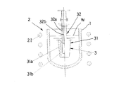
以下、本発明に係わる軽金属または軽合金の鋳造方法の一実施形態を図面を参照しながら説明する。まず、図1,図2を参照しながら本発明方法を実施するための装置について説明する。この装置は、耐火性材料である黒鉛からなる坩堝1と、加熱装置2と、冷却体3とを備えている。
Hereinafter, an embodiment of a light metal or light alloy casting method according to the present invention will be described with reference to the drawings. First, an apparatus for carrying out the method of the present invention will be described with reference to FIGS. This apparatus includes a
上記坩堝1は図示しない基台に取り外し可能に設置されている。上記加熱装置2は、坩堝1の外周から離間されて、囲みかつ巻くようにして配置された加熱線21を有している。この加熱線21への電流は電流制御器(図示しない)により制御され、供給熱量が制御されるようになっている。上記冷却体3は、図示しない昇降機構により、坩堝1に収容される下位位置と坩堝2から外された上位位置との間で昇降されるようになっている。
The
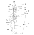
上記冷却体3は、大径の胴部31と小径の首部32とを備えている。胴部31は、下に向かってテーパをなす有底筒状の外殻31aと、有底円筒状の内殻31bの2重殻構造をなしている。また、首部32も外管32aと内管32bの2重管構造をなしている。外殻31aの上壁にはねじ穴31cが形成されており、このねじ穴31cに外管32aの下端をねじ込むことにより、外殻31aが外管32aに固定されている。内殻31bは、上端に連結筒部31dを有し、この連結筒部31dが内管32bの下端に嵌るようにして固定されている。なお、外殻31aと外管32aは伝熱性が高く耐食性材料である黒鉛により形成され、内殻31bと内管32bは鋼材からなる。
The
上記外管32aの下端より所定長さ上方の部位の外周には環状の鍔32cが形成されており、この鍔32cと外殻31aの上端面との間には、外殻31aと外管32aとの連結部を覆うカバー33が取り付けられている。このカバー33の円筒部は首部32の一部を構成し、下端鍔部は胴部31の一部を構成している。
An
上記外管32aの下端には径方向,内方向に張り出した鍔32dが形成されており、その内縁が内管32bの下端外周に嵌るようにして固定されている。鍔32dには周方向に等間隔をなして多数の通孔32eが形成されている。
A
上記内管32bと内殻31bの内側の空間は、第1通路35を構成している。また、上記外殻31aと内殻31bとの間の空間は、上記通孔32eを介して外管32aと内管32bとの間の空間と連なっており、これら空間は第2通路36を構成している。内殻31bの周壁には、第1通路35と,第2通路36とを連通させる多数の通孔31eが形成されている。これら第1通路35と第2通路36とで媒体通路が構成される。
A space inside the
上記外管32aの上端は、連結管37を介して図示しない回転機構に連結され、この回転機構を介して上記昇降機構に連結されている。回転機構は、冷却体3をその軸芯回りに回転させるようになっている。上記内管32bの上端は、圧縮エア(冷媒)の供給装置の出力端に回転自在に接続されている。
The upper end of the
上記構成をなす装置の作用を説明する。材料として例えば鋳造用アルミ合金を用いる。加熱装置2により坩堝1を予め所定温度Ta(アルミの液相温度より高い温度)に加熱しておく。この坩堝1に所定温度Taに加熱されたアルミ溶湯Wを注いだ後、溶湯W中に冷却体3の胴部31を埋没させる。冷却体3は予め図示しない加熱手段により上記所定温度Taまたはそれより若干低い温度に加熱されている。この冷却体3の予熱は、上記溶湯Wの上方近傍に位置させることにより行なってもよい。
The operation of the apparatus having the above configuration will be described. For example, a casting aluminum alloy is used as the material. The
上記冷却体3は回転することにより溶湯Wを撹拌する。溶湯Wの液面が冷却体3の小径の首部32に位置しているため、液面の乱れが少なく、空気の取りこみ量を抑制することができる。
The cooling
上記冷却体3は、回転と同時に圧縮エアの供給を受ける。常温の圧縮エアは内管32bの上端から第1通路35を通り、内殻31bの通孔31eから外殻31aに向かって噴出し、外殻31aを冷却した後、第2通路36を上昇して外部に排出される。これにより液相線温度以上の溶湯Wが冷却されて、液相線温度と固相線温度の間の所定温度Tbとなり、半凝固状態のスラリーとなる。上述したように溶湯W中に埋没された大径の胴部31が広い面積を有しているので、溶湯Wを効率良く冷却することができる。冷却時間は例えば30秒〜5分間である。
The cooling
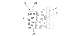
溶湯Wないしはスラリー状態の材料が上記冷却体3の外面に接すると多くの微小の凝固核(図3において符号Gで示す)が生成され、この凝固核が冷却体3の回転遠心力や材料との摩擦により冷却体3の外面から離れて溶湯中ないしはスラリー中に分散する。この凝固核分散は上記冷却体3の回転による撹拌作用でさらに促進される。生成された凝固核が冷却体3の外面から離れるので新たな凝固核がこの外面に形成されることになる。この繰り返しにより、凝固核を効率良く生成することができる。なお、胴部31が広い面積を有しているので、この点からも凝固核を効率良く生成することができる。この凝固核を基に初晶が形成される。成長しすぎた大きいサイズの結晶はこの撹拌により壊されて小さくなる。
When the molten W or slurry material comes into contact with the outer surface of the
上記冷却体3による溶湯Wの冷却と並行して、加熱装置2による坩堝1の加熱が続けられる。ただし、上記溶湯Wの冷却が開始されてから、供給熱量を徐々に低減し、坩堝1の外周面の温度を冷却終了時点で所定温度Tcにする。この温度Tcは上記Taより低いが液相線温度より高い。
In parallel with the cooling of the molten metal W by the cooling
上記坩堝1の外側からの加熱により、溶湯ないしはスラリー状態の材料の温度勾配が得られ、冷却体3の周面近傍で凝固核が集中的に生成される。しかも、冷却体3の冷却による溶湯の温度低下の勾配を緩めることができ、半凝固状態を十分な時間維持して十分な量の凝固核を生成することができる。この際、内側で冷却,外側で加熱を行なうので、互いに直接的な干渉をすることなく、良好な制御を行なうことができる。
By heating from the outside of the
上記凝固核は半凝固状態で成長して初晶となる。冷却終了時点において、スラリーは冷却体3の回転撹拌作用により過冷状態となっている。すなわち、撹拌が無い場合の温度に対応する固相率より固相率が低い。換言すれば、実際の固相率に対応する温度よりスラリー温度が低くなっている。
The solidification nuclei grow in a semi-solid state and become primary crystals. At the end of cooling, the slurry is supercooled by the rotating stirring action of the
上記スラリーを鋳型に鋳込むことにより、鋳物品が得られる。鋳型は、例えばポーラスな黒鉛材料からなる断熱性の下型と、通常の鋼材からなる上型とを有している。上記のようにスラリーは過冷されているので、急速に凝固する。この際多くの初晶が成長して球状の微小の結晶粒となる。微細な組織であるため、強度,加工性を高めることができる。上記下型は凝固速度を緩和するために断熱性にしているが、過冷度が小さい場合には、断熱性にしなくてもよい。 A cast article is obtained by casting the slurry into a mold. The mold has, for example, a heat insulating lower mold made of a porous graphite material and an upper mold made of a normal steel material. Since the slurry is supercooled as described above, it rapidly solidifies. At this time, many primary crystals grow into spherical fine crystal grains. Since it is a fine structure, strength and workability can be improved. The lower mold is made heat-insulating in order to reduce the solidification rate. However, when the degree of supercooling is small, it does not have to be made heat-insulating.
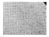
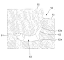
次に、鋳造用アルミ(JIS規格AC4CH)を材料として用いた場合のより具体的な実施例について説明する。このアルミの液相線温度は620°Cであり、固相線温度は555°Cである。坩堝1の内径は100mmであり冷却体3の最大径部の外径は50mmである。6Kgのアルミ溶湯をTa=700°Cにして坩堝1に注ぎ、この後、冷却体3を上述したように溶湯中に埋没させて、600rpmで回転させながら圧縮エアで冷却することにより、1分間でTb=590°Cの半凝固のスラリーを得る。この590°Cでの固相率は非撹拌状態であれば50〜55%であるが、撹拌しているので過冷状態となり、固相率は40〜45%となっている。なお、加熱装置2の加熱制御により、坩堝1の外周温度は700°Cから徐々に低下し、冷却終了時点で650°Cになる。次に、スラリーを図示しない鋳型に鋳込んで、鋳造品を得る。その結果、図4に示すように微細なαアルミの球状結晶粒とその間のアルミ・シリコンの共晶からなる組織を得ることができた。
Next, a more specific example in the case of using aluminum for casting (JIS standard AC4CH) as a material will be described. The liquidus temperature of this aluminum is 620 ° C., and the solidus temperature is 555 ° C. The inner diameter of the
図5は、鋳物品が車両用ホイールである場合の鋳型50を示す。この鋳型50は下型51と上型52とを備えている。下型51にスラリーを注いだ後に上型52を被せて型締めして成形する。鋳型50が型締め状態にある時、成形用キャビティ60が形成され、この成形用キャビティ60は、ディスク成形用空間61と、リム原形部成形用空間62とを有している。このリム原形部成形用空間62は、フランジ成形部62aと厚肉成形部62bとを有している。
FIG. 5 shows a
鋳造された車両ホイールは、ディスク成形用空間61に対応するディスクと、リム原形部成形用空間62に対応するリム原形部を有している。リム原形部は、フランジ成形部62aに対応する環状のフランジと、厚肉成形部62bに対応する環状の厚肉部とを有している。上記鋳造後に、厚肉部をスピニング加工して一対のビードシート,リムドロップ,他方のフランジを得る。
The cast vehicle wheel has a disk corresponding to the
本発明は上記実施形態に制約されず、種々の態様を採用可能である。例えば材料を坩堝1で加熱装置2により溶かすようにしてもよい。
上記坩堝は、熔解したアルミに耐食性のある鉄合金で作られた鉄坩堝、もしくは鉄坩堝の内面に耐食材を被覆したものでも良い。また、坩堝を使用しない反射炉方式の炉で耐食性のあるセラミック(窒化珪素やアルミナなど)を内張りにした炉を使用することもできる。
上記鋳造品は、上記鋳造により最終製品またはそれに近い製品としてもよいし、一次加工品とし、その後で押出成形等の2次加工をしてもよい。なお、鋳造せずに固相率の高いスラリーの状態で押出成形してもよい。
また、アルミ以外のマグネシウム,チタン等の軽金属,軽合金を材料として用いても良い。
過冷状態を解消してから、鋳造を行なってもよい。
スポンジ金属の鋳造品を製造する場合には、冷却終了後にスラリーに発泡材を添加する。
The present invention is not limited to the above embodiment, and various aspects can be adopted. For example, the material may be melted by the
The crucible may be an iron crucible made of an iron alloy having corrosion resistance on melted aluminum, or an inner surface of the iron crucible coated with a corrosion resistant material. Further, it is also possible to use a furnace with a corrosion-resistant ceramic (such as silicon nitride or alumina) lined in a reflection furnace type furnace that does not use a crucible.
The cast product may be a final product or a product close thereto by the casting, or may be a primary processed product, and then subjected to secondary processing such as extrusion. In addition, you may extrude in the state of a slurry with a high solid-phase rate, without casting.
Moreover, you may use light metals, such as magnesium other than aluminum, titanium, and a light alloy other than aluminum.
Casting may be performed after the overcooling state is eliminated.
In the case of producing a sponge metal casting, a foaming material is added to the slurry after cooling.
1 坩堝
2 加熱装置
3 冷却体
31 胴部
31a 外殻
31b 内殻
31e 通孔
32 首部
32a 外管
32b 内管
35 第1通路
36 第2通路
W 溶湯
G 凝固核
1
Claims (6)
Priority Applications (1)
| Application Number | Priority Date | Filing Date | Title |
|---|---|---|---|
| JP2004116854A JP2005297003A (en) | 2004-04-12 | 2004-04-12 | Method for producing semi-solidified slurry of light metal or light alloy, and casting method therefor |
Applications Claiming Priority (1)
| Application Number | Priority Date | Filing Date | Title |
|---|---|---|---|
| JP2004116854A JP2005297003A (en) | 2004-04-12 | 2004-04-12 | Method for producing semi-solidified slurry of light metal or light alloy, and casting method therefor |
Publications (1)
| Publication Number | Publication Date |
|---|---|
| JP2005297003A true JP2005297003A (en) | 2005-10-27 |
Family
ID=35329183
Family Applications (1)
| Application Number | Title | Priority Date | Filing Date |
|---|---|---|---|
| JP2004116854A Pending JP2005297003A (en) | 2004-04-12 | 2004-04-12 | Method for producing semi-solidified slurry of light metal or light alloy, and casting method therefor |
Country Status (1)
| Country | Link |
|---|---|
| JP (1) | JP2005297003A (en) |
Cited By (6)
| Publication number | Priority date | Publication date | Assignee | Title |
|---|---|---|---|---|
| CN105665654A (en) * | 2016-04-06 | 2016-06-15 | 上海应用技术学院 | Method and device for preparing semi-solid state slurry through intensive cooling stirring |
| WO2016115954A1 (en) * | 2015-01-21 | 2016-07-28 | 中兴通讯股份有限公司 | Device and method for preparing semi-solid metal slurry |
| JP2018536544A (en) * | 2015-12-02 | 2018-12-13 | ジュハイ ルンシンタイ エレクトリカル カンパニー リミテッド | Method and apparatus for producing semi-solid slurry |
| CN109226700A (en) * | 2018-10-25 | 2019-01-18 | 上海应用技术大学 | U-shaped water cooling stirring prepares semi-solid metal slurry device and method |
| CN113198983A (en) * | 2021-04-23 | 2021-08-03 | 上海应用技术大学 | Method and device for preparing medium cooling planetary stirring semi-solid slurry |
| CN113275520A (en) * | 2020-02-19 | 2021-08-20 | 丰田自动车株式会社 | Method for producing semi-solidified molten metal |
-
2004
- 2004-04-12 JP JP2004116854A patent/JP2005297003A/en active Pending
Cited By (10)
| Publication number | Priority date | Publication date | Assignee | Title |
|---|---|---|---|---|
| WO2016115954A1 (en) * | 2015-01-21 | 2016-07-28 | 中兴通讯股份有限公司 | Device and method for preparing semi-solid metal slurry |
| JP2018536544A (en) * | 2015-12-02 | 2018-12-13 | ジュハイ ルンシンタイ エレクトリカル カンパニー リミテッド | Method and apparatus for producing semi-solid slurry |
| US11059094B2 (en) | 2015-12-02 | 2021-07-13 | Zhuhai Runxingtai Electrical Co., Ltd. | Method and device for preparing semi-solid slurry |
| CN105665654A (en) * | 2016-04-06 | 2016-06-15 | 上海应用技术学院 | Method and device for preparing semi-solid state slurry through intensive cooling stirring |
| CN109226700A (en) * | 2018-10-25 | 2019-01-18 | 上海应用技术大学 | U-shaped water cooling stirring prepares semi-solid metal slurry device and method |
| CN109226700B (en) * | 2018-10-25 | 2020-06-23 | 上海应用技术大学 | U-shaped water-cooled stirring device and method for preparing semi-solid metal slurry |
| CN113275520A (en) * | 2020-02-19 | 2021-08-20 | 丰田自动车株式会社 | Method for producing semi-solidified molten metal |
| JP2021130118A (en) * | 2020-02-19 | 2021-09-09 | トヨタ自動車株式会社 | Manufacturing method of semi-solidified molten metal |
| JP7247917B2 (en) | 2020-02-19 | 2023-03-29 | トヨタ自動車株式会社 | Method for producing semi-solidified molten metal |
| CN113198983A (en) * | 2021-04-23 | 2021-08-03 | 上海应用技术大学 | Method and device for preparing medium cooling planetary stirring semi-solid slurry |
Similar Documents
| Publication | Publication Date | Title |
|---|---|---|
| JP3211754B2 (en) | Equipment for manufacturing metal for semi-solid molding | |
| CN100566890C (en) | A kind of equipment for preparation and rheological molding of semi-solid alloy slurry | |
| CN104232953B (en) | A kind of light metal alloy preparation method of semisolid state slurry thereof | |
| EP0841406A1 (en) | Method of shaping semisolid metals | |
| JP3549054B2 (en) | Method and apparatus for producing metallic material in solid-liquid coexistence state, method and apparatus for producing semi-solid metal slurry | |
| JPH1133692A (en) | Manufacture of metallic slurry for semi-solidified casting | |
| JP2005297003A (en) | Method for producing semi-solidified slurry of light metal or light alloy, and casting method therefor | |
| JP5157684B2 (en) | Hypereutectic Al-Si alloy casting method and ingot | |
| JP3246363B2 (en) | Forming method of semi-molten metal | |
| CN113069971A (en) | Preparation device and preparation method of metal semi-solid slurry | |
| CN100574939C (en) | A device for preparing and forming semi-solid alloy slurry | |
| JPH0910893A (en) | Equipment for manufacturing metal for semi-solid molding | |
| JPH09137239A (en) | Forming method of semi-molten metal | |
| JP3246358B2 (en) | Forming method of semi-molten metal | |
| JP2003183756A (en) | Aluminum alloy for semi-solid molding | |
| JP3919810B2 (en) | Method for producing semi-solid metal slurry, molding method and molded product | |
| JP3491468B2 (en) | Method for forming semi-solid metal | |
| CN110387478A (en) | A kind of semi-continuous casting method of Al-Si alloy ingots | |
| JP7724100B2 (en) | METAL REFINING METHOD AND METAL REFINING APPARATUS | |
| JPH0987773A (en) | Forming method of semi-molten metal | |
| JPS6039133A (en) | Manufacturing apparatus of alloy slurry | |
| JP2004255422A (en) | Apparatus and method for producing solid-liquid metal slurry | |
| JPH11138248A (en) | Semisolid forming method and production of semisolidified metallic slurry used to this | |
| JP4748688B2 (en) | Method for preparing semi-solid metal slurry | |
| JP4931455B2 (en) | Method for producing semi-solid metal slurry for rheocast |
Legal Events
| Date | Code | Title | Description |
|---|---|---|---|
| A621 | Written request for application examination |
Effective date: 20060615 Free format text: JAPANESE INTERMEDIATE CODE: A621 |
|
| A977 | Report on retrieval |
Free format text: JAPANESE INTERMEDIATE CODE: A971007 Effective date: 20061228 |
|
| A131 | Notification of reasons for refusal |
Free format text: JAPANESE INTERMEDIATE CODE: A131 Effective date: 20090324 |
|
| A521 | Written amendment |
Effective date: 20090521 Free format text: JAPANESE INTERMEDIATE CODE: A523 |
|
| A02 | Decision of refusal |
Effective date: 20090616 Free format text: JAPANESE INTERMEDIATE CODE: A02 |