JP2005296986A - Repair welding method for welded structures with excellent brittle crack propagation resistance - Google Patents
Repair welding method for welded structures with excellent brittle crack propagation resistance Download PDFInfo
- Publication number
- JP2005296986A JP2005296986A JP2004115000A JP2004115000A JP2005296986A JP 2005296986 A JP2005296986 A JP 2005296986A JP 2004115000 A JP2004115000 A JP 2004115000A JP 2004115000 A JP2004115000 A JP 2004115000A JP 2005296986 A JP2005296986 A JP 2005296986A
- Authority
- JP
- Japan
- Prior art keywords
- welded
- brittle crack
- brittle
- welding
- weld
- Prior art date
- Legal status (The legal status is an assumption and is not a legal conclusion. Google has not performed a legal analysis and makes no representation as to the accuracy of the status listed.)
- Granted
Links
Images
Landscapes
- Butt Welding And Welding Of Specific Article (AREA)
- Arc Welding In General (AREA)
Abstract
【課題】万一、溶接継手に脆性き裂が発生した場合に、補修溶接部にて脆性き裂の伝播を防止して溶接構造体の致命的な破断を防止できる溶接構造体の補修溶接方法を提供する。
【解決手段】 突合せ溶接継手に発生した脆性き裂の伝播を妨げる耐脆性き裂伝播性に優れた溶接構造体の補修溶接方法であって、溶接部に沿って脆性き裂が伝播する可能性のある溶接継手の、脆性き裂を停止させたい領域に対し、該領域の突合せ溶接継手の一部を、両表面よりガウジング、あるいは機械加工により、板厚中心部を板厚の1/10以上かつ1/3以下残存させながら部分的に除去した後、該除去部分に破壊靭性の優れた溶接材料で補修溶接を実施することにより、突合せ溶接継手に沿って伝播している脆性き裂を当該突合せ溶接部から逸らせて母材部に脆性き裂を導きだすことを特徴とする、耐脆性き裂伝播性に優れた溶接構造体の溶接方法。
【選択図】図3[PROBLEMS] To repair a welded structure capable of preventing a fatal fracture of a welded structure by preventing the propagation of the brittle crack in a repair weld in the event of a brittle crack occurring in a welded joint. I will provide a.
SOLUTION: A welding method for repairing a welded structure excellent in brittle crack propagation resistance that prevents the propagation of brittle cracks generated in a butt weld joint, and the possibility of brittle cracks propagating along the welded portion. For a welded joint with an area where it is desired to stop brittle cracks, part of the butt welded joint in this area is gouged or machined from both surfaces, and the center of the thickness is 1/10 or more of the thickness. In addition, after partially removing while remaining 1/3 or less, by carrying out repair welding with a welding material having excellent fracture toughness to the removed portion, the brittle crack propagating along the butt weld joint is A welding method for a welded structure excellent in brittle crack propagation resistance, characterized by deviating from a butt weld and introducing a brittle crack in a base material.
[Selection] Figure 3
Description
本発明は、突合せ溶接継手に発生した脆性き裂の伝播を妨げる耐脆性き裂伝播性に優れた溶接構造体の補修溶接方法に関する。
具体的には、厚板を用いて大入熱溶接を適用した溶接構造物の溶接継手に発生する可能性のある脆性き裂の伝播を妨げる耐脆性き裂伝播性に優れた溶接構造体の補修溶接方法に関するものであり、建築構造物や土木鋼構造物等の安全性を向上させうる技術に関する。
The present invention relates to a repair welding method for a welded structure excellent in brittle crack propagation resistance that prevents the propagation of a brittle crack generated in a butt weld joint.
Specifically, a welded structure excellent in brittle crack propagation resistance that hinders the propagation of brittle cracks that may occur in welded joints of welded structures to which large heat input welding is applied using thick plates. The present invention relates to a repair welding method, and relates to a technique capable of improving the safety of a building structure, a civil engineering steel structure, and the like.
鋼構造物を建造するためには溶接を用いることが必須であるが、建造コストを低減させたり建造能率を向上させる目的で、大入熱溶接が広く適用されている。特に、鋼板の板厚が増大すると、溶接の工数が飛躍的に増加するため、極限まで大入熱で溶接しようとする要求が高い。
しかし、大入熱溶接を適用すると、溶接熱影響(HAZ)部の靭性値が低下し、HAZ部の幅も増大するため、脆性破壊に対する破壊靭性値が低下する傾向にある。
そのため、大入熱溶接を適用してもHAZ部の破壊靭性が低下しにくい鋼材として、たとえば特許文献1、2等で開示されている発明がなされている。これらの発明では脆性破壊の発生に対する抵抗値である破壊靭性値は向上されているため、通常の使用環境では脆性破壊する可能性は極めて低く抑えられているが、地震や構造物同士の衝突、といった事故、災害等の非常時に万一脆性破壊が発生してしまうと、脆性き裂はHAZ部を伝播し、大規模な破壊に至る危険性が有る。
これまで、板厚25mm程度のTMCP鋼板等が使用されている溶接継手では、脆性き裂が発生しても、溶接部の残留応力により、脆性き裂が溶接継手部から母材側に逸れていくので、母材のアレスト性能を確保しさえすれば、万一、溶接継手部で脆性き裂が発生しても母材で脆性き裂を停止できると考えられてきた。
In order to build a steel structure, it is essential to use welding, but large heat input welding is widely applied for the purpose of reducing the construction cost and improving the construction efficiency. In particular, as the thickness of the steel sheet increases, the number of welding steps increases dramatically, so that there is a high demand for welding with high heat input to the limit.
However, when high heat input welding is applied, the toughness value of the weld heat affected (HAZ) portion decreases and the width of the HAZ portion also increases, so the fracture toughness value against brittle fracture tends to decrease.
Therefore, inventions disclosed in, for example, Patent Documents 1 and 2 and the like have been made as steel materials in which the fracture toughness of the HAZ portion is not easily lowered even when high heat input welding is applied. In these inventions, since the fracture toughness value, which is a resistance value against the occurrence of brittle fracture, has been improved, the possibility of brittle fracture in a normal use environment is extremely low, but earthquakes and collisions between structures, If a brittle fracture occurs in an emergency such as an accident or disaster, the brittle crack propagates through the HAZ part and there is a risk of large-scale fracture.
Until now, in welded joints where TMCP steel sheets with a thickness of about 25 mm have been used, even if a brittle crack occurs, the brittle crack is displaced from the welded joint to the base metal side due to residual stress in the weld. Therefore, it has been considered that if the arresting performance of the base metal is ensured, the base metal can stop the brittle crack even if a brittle crack occurs in the welded joint.
しかしながら、鋼構造物が大型化することで、より板厚の大きい鋼板が使用されるようになり、また構造を簡素化するためにも鋼板の厚肉化が有効であるため、設計応力が高い高張力鋼の厚鋼板が使用されるようになってきている。このような厚鋼板では、溶接継手部の破壊靭性の程度によっては、脆性き裂が母材に逸れることなく、溶接継手部の熱影響域に沿って伝播することが本発明者の8000トン大型試験機による大型破壊試験により明らかとなった。
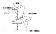
本発明者らによる鋼板の脆性破壊に係る試験によれば、板厚50mm以下の鋼板に、図1に示すように、鋼板の溶接継手部と交差するように隅肉溶接により骨材(補強板)を取り付けると、鋼板に脆性き裂が発生しても骨材により脆性き裂の伝播が止められて(アレスト)、鋼板の破断に至らないことも多い。
しかし、板厚が50mmを超え、70mm程度と板厚が厚くなると、骨材が取り付けられていても、骨材とは無関係に、母材に逸れることなく、HAZ部あるいは溶接金属部に沿って脆性き裂が伝播してしまうことのあることを知見した。
According to the test relating to the brittle fracture of a steel sheet by the present inventors, an aggregate (reinforcing plate) is formed on a steel sheet having a thickness of 50 mm or less by fillet welding so as to intersect the welded joint portion of the steel sheet as shown in FIG. ), Even if a brittle crack occurs in the steel sheet, the propagation of the brittle crack is stopped by the aggregate (arrest), and the steel sheet often does not break.
However, if the plate thickness exceeds 50 mm and the plate thickness is as thick as about 70 mm, even if the aggregate is attached, the HAZ portion or the weld metal portion does not deviate from the base material regardless of the aggregate. It has been found that a brittle crack may propagate.
そこで、本発明は、万一、突合せ溶接継手に脆性き裂が発生した場合に、溶接部にて脆性き裂の伝播を防止して溶接構造体の致命的な破断を防止できる溶接構造体の補修溶接方法を提供することを課題とする。 Therefore, the present invention provides a welded structure that can prevent the fatal fracture of the welded structure by preventing the propagation of the brittle crack in the welded part in the event that a brittle crack occurs in the butt weld joint. It is an object to provide a repair welding method.
本発明者らは、溶接構造体において、特定の補修溶接を行うことによって、溶接継手の脆性き裂伝播を防止して大規模破壊を未然に防止することができることを見出し本発明を完成したものであり、その要旨とするところは、下記のとおりである。
(1) 突合せ溶接継手に発生した脆性き裂の伝播を妨げる耐脆性き裂伝播性に優れた溶接構造体の補修溶接方法であって、溶接部に沿って脆性き裂が伝播する可能性のある溶接継手の、脆性き裂を停止させたい領域に対し、該領域の突合せ溶接継手の一部を、両表面よりガウジング、あるいは機械加工により、板厚中心部を板厚の1/10以上かつ1/3以下残存させながら部分的に除去した後、該除去部分に破壊靭性の優れた溶接材料で補修溶接を実施することにより、突合せ溶接継手に沿って伝播している脆性き裂を当該突合せ溶接部から逸らせて母材部に脆性き裂を導きだすことを特徴とする、耐脆性き裂伝播性に優れた溶接構造体の溶接方法。
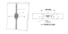
(2) 前記溶接部の部分的な除去に際し、除去加工部端部と鋼板表面とのなす角度を45°以下とすることを特徴とする、上記(1)に記載の耐脆性き裂伝播性に優れた溶接構造体の溶接方法。
(3) 前記溶接部の部分的な除去に際し、除去加工部部分の表面での幅を、溶接ビード幅と板厚との和以上とすることを特徴とする、上記(1)または(2)に記載の耐脆性き裂伝播性に優れた溶接構造体の溶接方法。
The inventors of the present invention have found that by performing specific repair welding in a welded structure, brittle crack propagation of a welded joint can be prevented and large-scale fracture can be prevented in advance. The gist of this is as follows.
(1) A repair welding method for welded structures with excellent brittle crack propagation that prevents the propagation of brittle cracks generated in butt welded joints, and the possibility of brittle cracks propagating along the weld For an area where a brittle crack is to be stopped in a welded joint, a part of the butt welded joint in this area is gouged or machined from both surfaces, and the center of the thickness is 1/10 or more of the thickness. After partially removing while remaining 1/3 or less, repair welding is performed on the removed portion with a welding material having excellent fracture toughness, thereby preventing the brittle crack propagating along the butt weld joint A method for welding a welded structure excellent in brittle crack propagation resistance, characterized in that a brittle crack is led to a base metal part by deviating from a welded part.
(2) The brittle crack propagation property according to (1) above, wherein an angle formed between an end portion of the removed processed portion and the steel plate surface is set to 45 ° or less during partial removal of the welded portion. Excellent welding method for welded structures.
(3) In the partial removal of the welded portion, the width at the surface of the removed processed portion is not less than the sum of the weld bead width and the plate thickness, (1) or (2) The welding method of the welded structure excellent in the brittle crack propagation property described in 1.
本発明によれば、万一、溶接継手に脆性き裂が発生した場合に、溶接部にて脆性き裂の伝播を防止して溶接構造体の致命的な破断を防止できる溶接構造体の補修溶接方法を提供することができ、産業上有用な著しい効果を奏する。 According to the present invention, in the unlikely event that a brittle crack occurs in a welded joint, repair of the welded structure that can prevent the fatal fracture of the welded structure by preventing the propagation of the brittle crack at the welded portion. A welding method can be provided, and the industrially useful remarkable effect is produced.
本発明を実施するための最良の形態について図2乃至図4を用いて詳細に説明する。
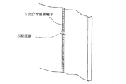
図2は、本発明の溶接方法を適用する鋼板の突合せ溶接継手を示す図である。図2において、5は突合せ溶接継手、6は補修溶接部を示す。本発明の補修溶接は、図2に示すような、脆性き裂が伝播する可能性のある突合せ溶接継手5において、脆性き裂を停止させる領域に対し、当該領域の突合せ溶接継手の一部をガウジング、あるいは機械加工により除去した後、当該部分に破壊靭性の優れた溶接材料で補修溶接を実施することを特徴とする。溶接継手にて発生した脆性き裂は、突合せ溶接継手5を伝播するが、脆性き裂を停止させる領域に対し、当該領域の突合せ溶接継手の一部をガウジング、あるいは機械加工により除去した後、当該部分に破壊靭性の優れた溶接材料で補修溶接を実施することによって、この部分の靭性を高くしてき裂の伝播を防止することができる。
The best mode for carrying out the present invention will be described in detail with reference to FIGS.
FIG. 2 is a view showing a butt weld joint of steel plates to which the welding method of the present invention is applied. In FIG. 2, 5 is a butt weld joint, and 6 is a repair weld. In the repair welding of the present invention, as shown in FIG. 2, in the
図3は、本発明の溶接方法に用いる補修溶接部の詳細図である。図3において、5は突合せ溶接継手、6は補修溶接部、7は溶接部除去加工部を示す。本発明者等は、脆性き裂が伝播する可能性のある突合せ溶接部5において、除去加工部の形状を変えて実験を行い、除去加工部に残存板厚(図3のd)があるほうが、耐脆性き裂伝播性に優れることを見出した。これは、除去加工部を板厚中心部で板厚の1/10以上かつ1/3以下残存させることにより、脆性き裂の伝播位置を板厚中央部では母材熱影響部の細粒部とすることが可能となるため、溶接部での耐脆性き裂伝播性が向上し、脆性き裂を母材に逸らすことができるためである。また,除去加工部に残存板厚がある場合、補修溶接の施工上、溶接金属の裏側への溶け落ち等を防止するため、施工性が上がり溶接部の特性も向上する。本発明者等は、除去加工に際し片側からの施工と両側からの施工を比較する実験を行い、両側からの加工の方が耐脆性破壊伝播性に優れていることを見出した。
これと類似の現象は、非特許文献1において、溶接部の耐脆性破壊伝播性について、同等の鋼板と溶接材料の組み合わせで、片側からの溶接であるV開先と両側からの溶接であるX開先を比較した場合、両表面からの溶接であるX開先の方が良好であることが示されている。
FIG. 3 is a detailed view of the repair weld used in the welding method of the present invention. In FIG. 3, 5 is a butt weld joint, 6 is a repair weld, and 7 is a weld removal part. The inventors conducted an experiment by changing the shape of the removal processing portion in the
In Non-Patent Document 1, a phenomenon similar to this is described in the non-patent document 1, with respect to the brittle fracture propagation property of a welded part, a combination of an equivalent steel plate and a welding material, and a V groove that is welded from one side and X that is welded from both sides. When comparing the grooves, it is shown that the X groove, which is a weld from both surfaces, is better.
本発明者らは、種々の実験の結果、除去加工部端部と鋼板表面とのなす角度が溶接部の耐脆性き裂伝播性に大きく影響することを見出した。これは、脆性き裂は、主応力方向に垂直な経路を取る傾向があり、そのため、通常開先が傾いた継手の場合は、き裂の経路が部分的に母材にそれる傾向があることによると考えられる。例えば,溶接部の耐脆性破壊伝播性は、同等の鋼板と溶接材料の組み合わせの場合、溶接線が鋼板表面法線方向と一致するレ型開先やK開先より、溶接線が鋼板表面法線方向との角度が傾いているV開先やX開先の方が良好であることが知られている。これは脆性破面の面積を増加させることにより、脆性破壊の伝播に要するエネルギーを増加させ、伝播抵抗を上げることによると考えられる。
本発明者等は、実験の結果、除去加工部端部と鋼板表面との角度を45°以下とすることにより、溶接部での耐脆性き裂伝播性が向上し、脆性き裂を母材に逸らすことができることを見出した。
As a result of various experiments, the present inventors have found that the angle formed between the end portion of the removed processed portion and the steel plate surface greatly affects the brittle crack propagation property of the welded portion. This is because brittle cracks tend to take a path perpendicular to the principal stress direction, and in the case of joints with inclined grooves, the crack path tends to partially shift to the base metal. It is thought that. For example, the brittle fracture propagation resistance of the welded part is determined by the steel plate surface method in the case of a combination of an equivalent steel plate and welding material, with a weld line having a steel line surface method or a K groove with a weld line matching the steel plate surface normal direction. It is known that a V groove or an X groove whose angle with the line direction is inclined is better. This is considered to be due to increasing the propagation resistance by increasing the energy required for the propagation of brittle fracture by increasing the area of the brittle fracture surface.
As a result of the experiment, the inventors have determined that the angle between the end portion of the removed processed portion and the steel sheet surface is 45 ° or less, thereby improving the brittle crack propagation property at the welded portion and removing the brittle crack from the base material. I found out that it can be diverted to.
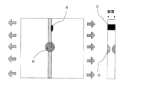
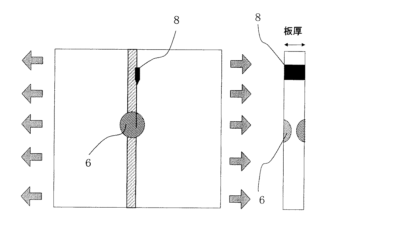
突合せ溶接部の一部に、ガウジング等により溶接部の一部を削除し、その部分に補修溶接を施し、その補修溶接部が脆性き裂の伝播を阻止しうる性能を発揮できるか否かを種々の試験を行った。試験にあたっては、直進してくる脆性き裂を阻止しうるか否かを評価するため、図4に示すように、2500mm×2500mmの鋼板を用い、その試験片中央部に種々の除去加工をガウジングまたは機械加工にて行い、補修溶接をした試験片を作製した。そして、その試験片端部から200mmの位置に楔を挿入して脆性き裂を発生させるためのV字の切り欠き加工を突き合わせ溶接部(エレクトロガス溶接による大入熱溶接継手)のフュージョンラインに一致するように施し、試験片端部を−40℃程度の低温に冷却し、試験片中央部をー10℃にコントロールして、所定の応力を負荷した後、V切り欠き部に楔を打ち込み、脆性き裂を発生させ、突合せ溶接部のフュージョンラインに沿って、脆性き裂を伝播させた。伝播した脆性き裂が、付加溶接部に到達した後、その脆性き裂が伝播するか否かを評価した。 Whether or not part of the butt weld is removed by gouging, etc., and repair welding is applied to the part, and whether or not the repair weld can exhibit the ability to prevent the propagation of brittle cracks. Various tests were performed. In the test, in order to evaluate whether or not a brittle crack that goes straight can be prevented, a 2500 mm × 2500 mm steel plate is used as shown in FIG. A test piece was prepared by machining and repair welding. Then, insert a wedge 200 mm from the end of the test piece to match the V-shaped notch for generating a brittle crack and match the fusion line of the butt weld (high heat input welded joint by electrogas welding) The test piece end is cooled to a low temperature of about −40 ° C., the center of the test piece is controlled at −10 ° C., and a predetermined stress is applied. A crack was generated and a brittle crack was propagated along the fusion line of the butt weld. After the propagated brittle crack reached the additional weld, it was evaluated whether the brittle crack propagated.
本発明の実施例を表1に示す。No.1〜No.11は、本発明に従って、溶接部を除去して補修溶接を行った本発明例であって、いずれの実施例も、耐き裂伝播性が良好であった。伝播位置がFL(Fusion Line)とは、き裂が溶融線に沿って伝播したことを示し、停止とは、き裂が補修溶接領域内で停止したことを示し、停止位置が母材とは、き裂が補修溶接領域内を伝播し母材に逸れて停止し、破断しなかった。
一方、No.12〜No.17は比較例であって、No.14〜No.17は溶接部の除去および補修溶接を行ったが、残存板厚d、除去加工部角度θ、除去加工部幅Wが本発明の範囲外のため、き裂が伝播した。即ち、No.12及びNo.13は残存板厚が0で除去角度が大きすぎたためき裂が溶融線に沿って伝播した。また、No.14及びNo.15は残存板厚が0で除去幅が小さすぎたためき裂が溶接金属に伝播した。また、No.16及びNo.17は、溶接部の除去および補修溶接を行わなかったので、突合せ溶接部で発生させた脆性き裂が、その溶接継ぎ手に沿って伝播し、試験片が真っ二つに破断した。
On the other hand, no. 12-No. No. 17 is a comparative example. 14-No. No. 17 removed and repaired the weld, but the crack propagated because the remaining thickness d, the removed portion angle θ, and the removed portion width W were outside the scope of the present invention. That is, no. 12 and no. In No. 13, the remaining plate thickness was 0 and the removal angle was too large, so the crack propagated along the melt line. No. 14 and no. In No. 15, the remaining plate thickness was 0 and the removal width was too small, so that the crack propagated to the weld metal. No. 16 and no. In No. 17, since the welded portion was not removed and repair welding was not performed, the brittle crack generated in the butt welded portion propagated along the weld joint, and the test piece broke into two.
1 鋼板
2 突合せ溶接継手部
3 骨材(補強材)
4 隅肉溶接部
5 突合せ溶接継手
6 補修溶接部
7 除去加工部、
8 切欠き
1 Steel plate 2 Butt weld joint 3 Aggregate (reinforcing material)
4 Fillet welded
8 Notch
Claims (3)
Priority Applications (2)
| Application Number | Priority Date | Filing Date | Title |
|---|---|---|---|
| JP2004115000A JP4858936B2 (en) | 2004-04-09 | 2004-04-09 | Method of imparting brittle crack propagation to welded structures |
| MYPI20051534 MY144819A (en) | 2004-04-09 | 2005-04-06 | Welded structure having excellent resistance to brittle crack propagation and welding method therefor |
Applications Claiming Priority (1)
| Application Number | Priority Date | Filing Date | Title |
|---|---|---|---|
| JP2004115000A JP4858936B2 (en) | 2004-04-09 | 2004-04-09 | Method of imparting brittle crack propagation to welded structures |
Publications (2)
| Publication Number | Publication Date |
|---|---|
| JP2005296986A true JP2005296986A (en) | 2005-10-27 |
| JP4858936B2 JP4858936B2 (en) | 2012-01-18 |
Family
ID=35329166
Family Applications (1)
| Application Number | Title | Priority Date | Filing Date |
|---|---|---|---|
| JP2004115000A Expired - Fee Related JP4858936B2 (en) | 2004-04-09 | 2004-04-09 | Method of imparting brittle crack propagation to welded structures |
Country Status (1)
| Country | Link |
|---|---|
| JP (1) | JP4858936B2 (en) |
Cited By (7)
| Publication number | Priority date | Publication date | Assignee | Title |
|---|---|---|---|---|
| JP4818467B1 (en) * | 2010-07-14 | 2011-11-16 | 新日本製鐵株式会社 | Welded joint and welded structure excellent in brittle crack propagation resistance |
| KR101197884B1 (en) | 2009-04-29 | 2012-11-05 | 주식회사 포스코 | Weld Structure |
| KR101724413B1 (en) | 2015-12-21 | 2017-04-10 | 주식회사 포스코 | Welded structure having excellent brittle crack propagation stopping performance and method for manufacturing the same |
| JP2017533828A (en) * | 2014-10-24 | 2017-11-16 | ゲーコーエヌ エアロスペース スウェーデン アーベー | Crack stopper for welds |
| WO2018122929A1 (en) * | 2016-12-26 | 2018-07-05 | 三菱電機株式会社 | Weld repair method and container |
| KR20190048313A (en) | 2017-10-31 | 2019-05-09 | 주식회사 포스코 | High Efficient Welded Joint Having Excellent Brittle Crack Propagation Stopping Performance and Method for Manufacturing the Same |
| CN116532758A (en) * | 2023-05-08 | 2023-08-04 | 安徽马钢设备检修有限公司 | Online welding device and repairing process for cracks of large ball mill cylinder |
Citations (2)
| Publication number | Priority date | Publication date | Assignee | Title |
|---|---|---|---|---|
| JPS51116141A (en) * | 1975-04-04 | 1976-10-13 | Mitsubishi Heavy Ind Ltd | Welding method |
| JPS63194801A (en) * | 1987-02-10 | 1988-08-12 | Sumitomo Metal Ind Ltd | Production of crack arrester steel product |
-
2004
- 2004-04-09 JP JP2004115000A patent/JP4858936B2/en not_active Expired - Fee Related
Patent Citations (2)
| Publication number | Priority date | Publication date | Assignee | Title |
|---|---|---|---|---|
| JPS51116141A (en) * | 1975-04-04 | 1976-10-13 | Mitsubishi Heavy Ind Ltd | Welding method |
| JPS63194801A (en) * | 1987-02-10 | 1988-08-12 | Sumitomo Metal Ind Ltd | Production of crack arrester steel product |
Cited By (10)
| Publication number | Priority date | Publication date | Assignee | Title |
|---|---|---|---|---|
| KR101197884B1 (en) | 2009-04-29 | 2012-11-05 | 주식회사 포스코 | Weld Structure |
| JP4818467B1 (en) * | 2010-07-14 | 2011-11-16 | 新日本製鐵株式会社 | Welded joint and welded structure excellent in brittle crack propagation resistance |
| WO2012008055A1 (en) * | 2010-07-14 | 2012-01-19 | 新日本製鐵株式会社 | Welded joint and welded structure having excellent brittle crack propagation resistance |
| JP2017533828A (en) * | 2014-10-24 | 2017-11-16 | ゲーコーエヌ エアロスペース スウェーデン アーベー | Crack stopper for welds |
| US11311972B2 (en) | 2014-10-24 | 2022-04-26 | Gkn Aerospace Sweden Ab | Crack stopper for welds |
| KR101724413B1 (en) | 2015-12-21 | 2017-04-10 | 주식회사 포스코 | Welded structure having excellent brittle crack propagation stopping performance and method for manufacturing the same |
| WO2018122929A1 (en) * | 2016-12-26 | 2018-07-05 | 三菱電機株式会社 | Weld repair method and container |
| JPWO2018122929A1 (en) * | 2016-12-26 | 2019-06-24 | 三菱電機株式会社 | Welding repair method and container |
| KR20190048313A (en) | 2017-10-31 | 2019-05-09 | 주식회사 포스코 | High Efficient Welded Joint Having Excellent Brittle Crack Propagation Stopping Performance and Method for Manufacturing the Same |
| CN116532758A (en) * | 2023-05-08 | 2023-08-04 | 安徽马钢设备检修有限公司 | Online welding device and repairing process for cracks of large ball mill cylinder |
Also Published As
| Publication number | Publication date |
|---|---|
| JP4858936B2 (en) | 2012-01-18 |
Similar Documents
| Publication | Publication Date | Title |
|---|---|---|
| JP4733955B2 (en) | Welding method of welded structure with excellent brittle crack propagation resistance | |
| JP4528089B2 (en) | Large heat input butt welded joints for ship hulls with brittle fracture resistance | |
| CN101443150A (en) | Welded structure excellent in brittle-cracking propagation stopping characteristics | |
| JP6744274B2 (en) | Welded structure | |
| CN103796786B (en) | Welded structure | |
| CN111433585B (en) | Evaluation method for brittle crack propagation stop performance of thick steel plate | |
| CN103874557B (en) | Welded structure | |
| JP5935395B2 (en) | Welding assembly groove part for square welding of four-sided box section | |
| JP4858936B2 (en) | Method of imparting brittle crack propagation to welded structures | |
| KR101197884B1 (en) | Weld Structure | |
| TWI332877B (en) | ||
| JP3811479B2 (en) | Weld metal for welded structure having excellent brittle fracture propagation resistance, its construction method, and welded structure | |
| KR20120111436A (en) | Weld structure and method for manufacturing the same | |
| CN102712063A (en) | Welded structures with resistance to brittle crack growth | |
| CN100537108C (en) | High heat input butt welding joint exhibiting excellent characteristics in resistance to occurrence of brittle fracture | |
| JP2009012049A (en) | Multilayer butt-welded joint and welded structure with excellent brittle crack propagation characteristics | |
| JP4091893B2 (en) | Butt weld joint excellent in brittle crack propagation resistance, method for producing the joint, and welded structure | |
| JP6720106B2 (en) | Welded structure | |
| JP2007268551A (en) | Multi-electrode one side submerged arc welding method | |
| KR102046957B1 (en) | High Efficient Welded Joint Having Excellent Brittle Crack Propagation Stopping Performance and Method for Manufacturing the Same | |
| JP6251463B1 (en) | Welded structure with excellent brittle crack propagation stop properties | |
| US20070000968A1 (en) | Weld structure having excellent resistance brittle crack propagation resistance and method of welding the weld structure | |
| KR100925621B1 (en) | Welding seam of steel and welding method of steel | |
| JP6852797B2 (en) | Laminated laser welded joints, manufacturing methods of lap laser welded joints and skeleton parts for automobiles | |
| KR101449209B1 (en) | Welding joint |
Legal Events
| Date | Code | Title | Description |
|---|---|---|---|
| A621 | Written request for application examination |
Free format text: JAPANESE INTERMEDIATE CODE: A621 Effective date: 20061113 |
|
| A977 | Report on retrieval |
Free format text: JAPANESE INTERMEDIATE CODE: A971007 Effective date: 20090410 |
|
| A131 | Notification of reasons for refusal |
Free format text: JAPANESE INTERMEDIATE CODE: A131 Effective date: 20090421 |
|
| A521 | Written amendment |
Free format text: JAPANESE INTERMEDIATE CODE: A523 Effective date: 20090622 |
|
| A131 | Notification of reasons for refusal |
Free format text: JAPANESE INTERMEDIATE CODE: A131 Effective date: 20100330 |
|
| A521 | Written amendment |
Free format text: JAPANESE INTERMEDIATE CODE: A523 Effective date: 20100528 |
|
| A02 | Decision of refusal |
Free format text: JAPANESE INTERMEDIATE CODE: A02 Effective date: 20110301 |
|
| A521 | Written amendment |
Free format text: JAPANESE INTERMEDIATE CODE: A523 Effective date: 20110721 |
|
| A01 | Written decision to grant a patent or to grant a registration (utility model) |
Free format text: JAPANESE INTERMEDIATE CODE: A01 |
|
| A61 | First payment of annual fees (during grant procedure) |
Free format text: JAPANESE INTERMEDIATE CODE: A61 Effective date: 20111026 |
|
| R151 | Written notification of patent or utility model registration |
Ref document number: 4858936 Country of ref document: JP Free format text: JAPANESE INTERMEDIATE CODE: R151 |
|
| FPAY | Renewal fee payment (event date is renewal date of database) |
Free format text: PAYMENT UNTIL: 20141111 Year of fee payment: 3 |
|
| FPAY | Renewal fee payment (event date is renewal date of database) |
Free format text: PAYMENT UNTIL: 20141111 Year of fee payment: 3 |
|
| S533 | Written request for registration of change of name |
Free format text: JAPANESE INTERMEDIATE CODE: R313533 |
|
| FPAY | Renewal fee payment (event date is renewal date of database) |
Free format text: PAYMENT UNTIL: 20141111 Year of fee payment: 3 |
|
| R350 | Written notification of registration of transfer |
Free format text: JAPANESE INTERMEDIATE CODE: R350 |
|
| S533 | Written request for registration of change of name |
Free format text: JAPANESE INTERMEDIATE CODE: R313533 |
|
| R350 | Written notification of registration of transfer |
Free format text: JAPANESE INTERMEDIATE CODE: R350 |
|
| LAPS | Cancellation because of no payment of annual fees |