JP2005296972A - Mold cooling structure - Google Patents
Mold cooling structure Download PDFInfo
- Publication number
- JP2005296972A JP2005296972A JP2004113402A JP2004113402A JP2005296972A JP 2005296972 A JP2005296972 A JP 2005296972A JP 2004113402 A JP2004113402 A JP 2004113402A JP 2004113402 A JP2004113402 A JP 2004113402A JP 2005296972 A JP2005296972 A JP 2005296972A
- Authority
- JP
- Japan
- Prior art keywords
- cooling
- cooling water
- hole
- valve block
- mold
- Prior art date
- Legal status (The legal status is an assumption and is not a legal conclusion. Google has not performed a legal analysis and makes no representation as to the accuracy of the status listed.)
- Pending
Links
- 238000001816 cooling Methods 0.000 title claims abstract description 143
- 239000000498 cooling water Substances 0.000 claims abstract description 190
- 238000011084 recovery Methods 0.000 claims abstract description 26
- XLYOFNOQVPJJNP-UHFFFAOYSA-N water Substances O XLYOFNOQVPJJNP-UHFFFAOYSA-N 0.000 claims abstract description 23
- 239000012778 molding material Substances 0.000 claims abstract description 13
- 230000002093 peripheral effect Effects 0.000 claims description 34
- 239000011799 hole material Substances 0.000 claims 27
- 238000007664 blowing Methods 0.000 abstract description 3
- 238000003860 storage Methods 0.000 description 8
- 238000004512 die casting Methods 0.000 description 7
- 229910052751 metal Inorganic materials 0.000 description 5
- 239000002184 metal Substances 0.000 description 5
- 229910000838 Al alloy Inorganic materials 0.000 description 4
- 230000033001 locomotion Effects 0.000 description 4
- 238000000465 moulding Methods 0.000 description 4
- 238000003825 pressing Methods 0.000 description 4
- 230000000694 effects Effects 0.000 description 3
- 230000007774 longterm Effects 0.000 description 3
- 239000000463 material Substances 0.000 description 3
- 229910045601 alloy Inorganic materials 0.000 description 2
- 239000000956 alloy Substances 0.000 description 2
- 238000005266 casting Methods 0.000 description 2
- 238000004891 communication Methods 0.000 description 2
- 239000002826 coolant Substances 0.000 description 2
- 238000003780 insertion Methods 0.000 description 2
- 230000037431 insertion Effects 0.000 description 2
- 238000007711 solidification Methods 0.000 description 2
- 230000008023 solidification Effects 0.000 description 2
- 239000007921 spray Substances 0.000 description 2
- 208000025599 Heat Stress disease Diseases 0.000 description 1
- 229910052782 aluminium Inorganic materials 0.000 description 1
- XAGFODPZIPBFFR-UHFFFAOYSA-N aluminium Chemical compound [Al] XAGFODPZIPBFFR-UHFFFAOYSA-N 0.000 description 1
- 230000000903 blocking effect Effects 0.000 description 1
- 230000026058 directional locomotion Effects 0.000 description 1
- 238000010438 heat treatment Methods 0.000 description 1
- 239000007788 liquid Substances 0.000 description 1
- 238000004519 manufacturing process Methods 0.000 description 1
- 238000004904 shortening Methods 0.000 description 1
- 238000005507 spraying Methods 0.000 description 1
Images
Landscapes
- Molds, Cores, And Manufacturing Methods Thereof (AREA)
- Moulds For Moulding Plastics Or The Like (AREA)
Abstract
【課題】 入子の破損に伴う湯吹きを回避すると共に破損の影響を極力抑制して補修コストの削減及び補修作業の短縮が可能な金型の冷却構造を提供する。
【解決手段】 金型1の入子7内に形成された冷却穴9に接続された冷却パイプ11に形成したバルブブロック収容部14に摺動可能にバルブブロック31を設ける。通常時はバルブブロック31が通常位置に保持されて冷却パイプ11及びバルブブロック31を経て冷却穴9に冷却水を供給及び回収して入子7を冷却する。一方、入子7の破損に伴い、キャビティ10から冷却穴9へ進入する溶融状態の成形材料による圧力でバルブブロック31が後退位置に移動して冷却水供給通路I及び冷却水回収通路IIを遮蔽する。
【選択図】 図1
PROBLEM TO BE SOLVED: To provide a mold cooling structure capable of avoiding hot water blowing due to breakage of an insert and suppressing the influence of breakage as much as possible to reduce repair cost and shorten repair work.
A valve block 31 is slidably provided in a valve block accommodating portion 14 formed in a cooling pipe 11 connected to a cooling hole 9 formed in a insert 7 of a mold 1. During normal operation, the valve block 31 is held in the normal position, and cooling water is supplied to and recovered from the cooling holes 9 through the cooling pipe 11 and the valve block 31 to cool the insert 7. On the other hand, when the insert 7 is damaged, the valve block 31 is moved to the retracted position by the pressure of the molten molding material entering the cooling hole 9 from the cavity 10 to shield the cooling water supply passage I and the cooling water recovery passage II. To do.
[Selection] Figure 1
Description
本発明は、ダイカスト鋳造等に使用される金型の冷却構造に関し、特に入子またはピンを備えた金型の冷却構造に関する。 The present invention relates to a mold cooling structure used for die casting or the like, and more particularly to a mold cooling structure having a nest or a pin.
ダイカスト鋳造は、精密に機械加工した金型のキャビティ内に成形材料、例えばアルミニウム合金等の溶融合金を高温で高圧力をかけて強制的に圧入し、短時間で凝固させることによって高精度で鋳肌が平滑な優れた鋳物を短時間で大量生産できることから、寸法精度の要求が高い自動車部品等の製造に広く利用されている。 Die casting is a highly accurate casting process in which a molding material, for example, a molten alloy such as an aluminum alloy, is forcibly press-fitted at a high temperature and solidified in a short time. Since it can mass-produce excellent castings with smooth skin in a short time, it is widely used in the production of automobile parts and the like that require high dimensional accuracy.
このダイカスト鋳造においては、安定した生産性や成形品の寸法精度等の品質を維持するために金型の温度を一定に保持することが好ましい。特に金型に設けられてキャビティ内に突出する入子はキャビティ内に圧入される湯、即ち高温のアルミニウム合金等の溶融合金からなる成形材料による熱的影響が大きい。この対策として入子内に形成された冷却穴に冷却パイプを接続すると共に、この冷却パイプ内に供給パイプを配置して供給パイプ内に供給路を形成すると共に供給パイプと冷却パイプとの間に戻し路を形成して、供給路側から冷却穴内に冷却水を供給して入子を冷却し、入子を冷却した冷却水を戻し路側から回収する金型の冷却構造が知られている(例えば、特許文献1、特許文献2参照)。 In this die casting, it is preferable to keep the temperature of the mold constant in order to maintain quality such as stable productivity and dimensional accuracy of a molded product. In particular, the insert provided in the mold and projecting into the cavity is greatly affected by the thermal effect of the molding material made of hot water press-fitted into the cavity, that is, a molten alloy such as a high-temperature aluminum alloy. As a countermeasure, a cooling pipe is connected to a cooling hole formed in the insert, and a supply pipe is arranged in the cooling pipe to form a supply path in the supply pipe and between the supply pipe and the cooling pipe. A mold cooling structure is known in which a return path is formed, cooling water is supplied into the cooling hole from the supply path side to cool the insert, and the cooling water that has cooled the insert is recovered from the return path side (for example, , See Patent Document 1 and Patent Document 2).
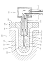
この種の金型の冷却構造について図4を参照して説明する。図4はダイカスト鋳造用の金型100の要部を示す断面図であり、図中矢印は冷却水の流れを示している。金型100は固定型101と可動型105を有し、固定金型101の製品成形面となるキャビティサイド102と可動型105のキャビティサイド106によって成形空間であるキャビティ110が形成される。可動型105にキャビティ110内に突出する入子107が取り付けられ、入子107の裏面108に一端が開口する有底の冷却穴109が形成されている。
This type of mold cooling structure will be described with reference to FIG. FIG. 4 is a cross-sectional view showing the main part of a
冷却穴109の一端に、先端側が螺合して冷却パイプ111が取り付けられ、冷却パイプ111の外方端に冷却水貯留室112が連設されている。冷却パイプ111内に先端113aが冷却パイプ111の先端111aより突出する供給パイプ113が貫通して、供給パイプ113内に供給路114を形成すると共に供給パイプ113と冷却パイプ111との間に冷却穴109と冷却水貯留室112内を連通する戻し路115を形成する。供給パイプ113は冷却水導入パイプ116を介して図示しない冷却水供給源に接続され、かつ冷却水貯留室112には冷却水回収パイプ117が連通されている。
The
この金型冷却構成により、冷却水供給源から冷却水導入パイプ116を介して送給される冷却水が供給パイプ113によって形成された供給路114を経て冷却穴109内に送られ、冷却穴109内で熱交換されて入子107を冷却した冷却水は冷却パイプ111と供給パイプ113の間に形成された戻し路115を経て冷却水貯留室112に送られ、更に冷却水貯留室112から冷却水回収パイプ117を介して回収される。
With this mold cooling configuration, the cooling water fed from the cooling water supply source via the cooling
上記図4に示す金型冷却構造によると、冷却水が冷却水導入パイプ116から供給パイプ113によって形成された供給路114を経て冷却穴109内に供給され、冷却穴109内で熱交換された冷却水が供給パイプ113と冷却パイプ111とによって形成された戻し路115を経て冷却水貯留室112に送られ、冷却水貯留室112から冷却水回収パイプ117によって回収される冷却水循環経路が形成されて入子107を冷却することができる。
According to the mold cooling structure shown in FIG. 4, the cooling water is supplied from the cooling
しかし、キャビティ110内に突出する入子107は、長期の使用によりキャビティ110内に圧入される湯、例えば高温のアルミニウム合金等の加熱溶融された成形材料による加熱の繰り返しに起因する熱疲労及び湯の凝固に伴う成形材料の収縮による応力付与によって図5に示すように破損することがある。
However, the
入子107が破損すると、キャビティ110内に高圧で圧入された高温の湯がその破損部分107aから矢印で示すように入子107に形成された冷却穴109内に進入し、供給路114及び戻し路115等を介して冷却水貯留室112から可動型105の裏面側に湯吹きし、更に、高温で高圧の湯が冷却水導入パイプ116や冷却水回収パイプ117に進入して冷却水導入パイプ116や冷却水回収パイプ117までの広範囲にわたって破損することが懸念される。
When the
このような湯吹きや冷却水導入パイプ116や冷却水回収パイプ117等の広範囲にわたって破損が発生すると、その補修に多くのコストを要すると共に、長期にわたる補修作業が必要となる。また、入子に代えてピンを備えた金型冷却構造においても同様なことが懸念される。
When such hot water spray, cooling
従って、かかる点に鑑みなされた本発明の目的は、入子またはピンの破損に伴う湯吹きを回避すると共に破損の影響を極力抑制して補修コストの削減及び補修作業の短縮が可能な金型の冷却構造を提供することにある。 Therefore, an object of the present invention made in view of the above points is to provide a mold capable of avoiding the hot water spray accompanying the breakage of the insert or the pin and reducing the repair cost and the repair work by suppressing the influence of the damage as much as possible. It is to provide a cooling structure.
上記目的を達成する請求項1に記載の金型冷却構造の発明は、固定型或いは可動型に設けられキャビティ内に突出する入子を有し、該入子内に形成されて入子の裏面に開口する有底の冷却穴に冷却水を供給及び回収して入子を冷却する金型の冷却構造において、上記冷却穴に接続されて上記入子の裏面から突出する冷却パイプと、上記入子の裏面から突出する上記冷却パイプの基端側に形成されたバルブブロック収容部と、該バルブブロック収容部内に通常位置と後退位置との間で摺動可能に収容されたバルブブロックとを有し、上記バルブブロックが通常位置において上記冷却パイプ及びバルブブロックを経て冷却水供給源からの冷却水を上記冷却穴に供給する冷却水供給通路及び冷却穴から冷却水を回収する冷却水回収通路が形成される一方、上記入子の破損に伴うキャビティ内から冷却穴へ進入する成形材料の圧力で上記バルブブロックが後退位置に移動して上記冷却水供給通路及び冷却水回収通路が遮蔽することを特徴とする。 The invention of the mold cooling structure according to claim 1, which achieves the above object, has a nest that is provided in a fixed mold or a movable mold and projects into a cavity, and is formed in the nest and is formed on the back surface of the nest. In a mold cooling structure that cools the insert by supplying and collecting cooling water to a bottomed cooling hole that opens to the bottom, a cooling pipe that is connected to the cooling hole and protrudes from the back surface of the insert, and the inlet A valve block housing portion formed on the base end side of the cooling pipe protruding from the rear surface of the child, and a valve block housed in the valve block housing portion so as to be slidable between a normal position and a retracted position. A cooling water supply passage for supplying cooling water from the cooling water supply source to the cooling hole via the cooling pipe and the valve block at a normal position and a cooling water recovery passage for collecting the cooling water from the cooling hole. It is formed On the other hand, the valve block is moved to the retracted position by the pressure of the molding material entering the cooling hole from the cavity due to the breakage of the insert, and the cooling water supply passage and the cooling water recovery passage are shielded. .
上記目的を達成する請求項2に記載の金型冷却構造の発明は、固定型或いは可動型に設けられキャビティ内に突出する入子を有し、該入子内に形成されて入子の裏面に開口する有底の冷却穴に冷却水を供給及び回収して入子を冷却する金型の冷却構造において、上記冷却穴に接続されて上記入子の裏面から突出する冷却パイプと、上記入子の裏面から突出する上記冷却パイプの基端側に形成された冷却水導入口及び冷却水排出口が開口するバルブブロック収容部と、該バルブブロック収容部内に通常位置と後退位置との間で摺動可能に収容されて冷却水供給孔及び冷却水戻し孔が形成されたバルブブロックとを有し、上記バルブブロックが通常位置において上記冷却水供給孔によって上記冷却水導入口と冷却穴が連通して冷却水供給源からの冷却水を上記冷却穴に供給する冷却水供給通路を形成し、かつ冷却水戻し孔によって上記冷却穴と冷却水排出口が連通して冷却穴から冷却水を回収する冷却水回収通路を形成する一方、上記入子の破損に伴うキャビティ内から冷却穴へ進入する成形材料の圧力でバルブブロックが後退位置に移動して上記冷却水供給通路及び冷却水回収通路が遮蔽することを特徴とする。
The invention of a mold cooling structure according to
請求項3に記載の発明は、請求項2の金型冷却構造において、上記バルブブロック収容部は、内周面を有する円筒状で周壁に上記冷却水導入口及び冷却水排出口が開口し、上記バルブブロックは、上記内周面に摺動可能に嵌合する外周面及び冷却穴内に対向する前面を有する円柱状で上記冷却水供給孔の入口及び冷却水戻し孔の出口がそれぞれ外周面に開口し冷却水供給孔の出口及び冷却水戻し孔の入口が前面に開口し、上記バルブブロックが通常位置において冷却水供給孔の入口及び冷却水戻し孔の出口がそれぞれ冷却水導入口及び冷却水排出口と連通し、後退位置において冷却水供給孔の入口及び冷却水戻し孔の出口がそれぞれバルブブロック収容部の内周面で遮蔽されることを特徴とする。
The invention according to
請求項4に記載の発明は、請求項1〜3のいずれか1つの金型冷却構造において、通常時において上記バルブブロックを通常位置に保持するバルブ保持手段を備えたことを特徴とする。 A fourth aspect of the present invention is the mold cooling structure according to any one of the first to third aspects, further comprising valve holding means for holding the valve block in a normal position in a normal state.
請求項5に記載の発明は、請求項3の金型冷却構造において、バルブブロックの前面に、基端が冷却水供給孔の出口に連通し先端が冷却穴内に突出する供給パイプを有することを特徴とする。 According to a fifth aspect of the present invention, in the mold cooling structure of the third aspect, the valve block has a supply pipe on the front surface of the valve block, the base end communicating with the outlet of the cooling water supply hole and the front end protruding into the cooling hole. Features.
請求項6に記載の発明は、請求項1〜5の金型冷却構造において、上記入子に代えてピンであることを特徴とする。 A sixth aspect of the present invention is the mold cooling structure according to any one of the first to fifth aspects, wherein a pin is used instead of the insert.
請求項1の発明によると、入子が破損してキャビティ内に高圧な溶融状態の成形材料が冷却穴内に進入した際には、その成形材料の圧力でバルブブロックが退避位置に移動して冷却水供給通路及び冷却水回収通路を冷却パイプ内で遮蔽する。この冷却パイプ内での冷却水供給通路及び冷却水回収通路の遮蔽により金型の湯吹きが防止でき、かつ入子及び入子に設けられた冷却パイプ等の極めて小範囲の破損に抑制することができ、その破損に伴う補修が、入子の交換修理、或いは入子及び冷却パイプ等の交換修理等の極めて容易な補修作業によって行え、補修コストの削減及び大幅な補修期間の短縮が可能になる。 According to the first aspect of the present invention, when the insert is damaged and a high-pressure molten molding material enters the cooling hole, the valve block is moved to the retracted position by the pressure of the molding material and cooled. The water supply passage and the cooling water recovery passage are shielded in the cooling pipe. By blocking the cooling water supply passage and the cooling water recovery passage in the cooling pipe, it is possible to prevent hot water from blowing in the mold, and to suppress the damage to a very small range such as the cooling pipe provided in the insertion and the insertion. Can be repaired by replacing the nesting or repairing the nesting and cooling pipes, etc., with extremely easy repair work, reducing repair costs and greatly shortening the repair period. Become.
請求項2の発明は、請求項1の構成をより具体的にしたもので、バルブブロック収容部に冷却水導入口及び冷却水排出口が開口し、バルブブロック収容部内に通常位置と後退位置との間で摺動可能に収容されたバルブブロックに冷却水供給孔及び冷却水戻し孔を形成して、バルブブロックの通常位置において冷却水供給孔によって冷却水導入口と冷却穴が連通する冷却水供給通路を形成し、かつ冷却水戻し孔によって冷却穴と冷却水排出口が連通する冷却水回収通路を形成する一方、上記入子の破損に伴うキャビティ内から冷却穴へ進入する溶融状態の成形材料の圧力でバルブブロックが後退位置に移動して冷却水供給通路及び冷却水回収通路が遮蔽する。この遮蔽により金型の湯吹きが防止でき、かつ入子及び入子に設けられた冷却パイプ等の極めて小範囲の破損に抑制することができ、その破損に伴う補修が入子の交換修理、或いは入子及び冷却パイプ等の交換修理等の極めて容易な補修作業によって行える。
The invention of
請求項3の発明は、バルブブロック収容部及びバルブブロックのより具体的構成に限定するもので、バルブブロックが通常位置では、冷却水供給孔の入口及び冷却水戻し孔の出口がそれぞれ外周面に開口し冷却水供給孔の出口及び冷却水戻し孔の入口が前面に開口して冷却水供給孔の入口及び冷却水戻し孔の出口がそれぞれ冷却水導入口及び冷却水排出口と連通し、後退位置において冷却水供給孔の入口及び冷却水戻し孔の出口がそれぞれバルブブロック収容部の内周面で遮蔽される。
The invention of
請求項4の発明によると、バルブ保持手段によって通常時においては、バルブブロックを通常位置に安定的に保持することができる。 According to the invention of claim 4, the valve block can be stably held at the normal position by the valve holding means in the normal time.
請求項5の発明によると、バルブブロックの前面に、基端が冷却水供給孔の出口に連通し先端が冷却穴内に突出する供給パイプを備えることによって、供給パイプ内に冷却水を冷却穴の先端側に誘導する冷却水供給路が形成され、供給パイプと冷却パイプとの間に入子を冷却した冷却水を戻す冷却水戻し路が形成されて効率的に入子を冷却することができる。 According to the fifth aspect of the present invention, the supply pipe having the base end communicating with the outlet of the cooling water supply hole and the front end protruding into the cooling hole is provided on the front surface of the valve block. A cooling water supply path that leads to the tip side is formed, and a cooling water return path that returns the cooling water that has cooled the insert is formed between the supply pipe and the cooling pipe, so that the insert can be efficiently cooled. .
請求項6の発明によると、ピンを備えた金型においても、上記請求項1〜5と同様の作用効果が得られる。 According to the sixth aspect of the present invention, the same effects as those of the first to fifth aspects of the present invention can be obtained even in a mold having pins.
本発明による金型冷却構造の実施の形態を図1乃至図3を参照して詳細に説明する。 An embodiment of a mold cooling structure according to the present invention will be described in detail with reference to FIGS.
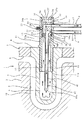
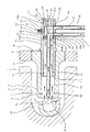
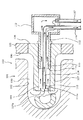
図1は、ダイカスト鋳造用の金型1の要部を示す断面図であり、図2及び図3は入子の破損状態における説明図である。なお、図1において矢印は冷却水の流れを示し、図2及び図3において矢印は湯、即ち溶融された成形材料の流れを示している。 FIG. 1 is a cross-sectional view showing a main part of a die 1 for die casting, and FIGS. 2 and 3 are explanatory views in a damaged state of the insert. In FIG. 1, the arrows indicate the flow of cooling water, and in FIGS. 2 and 3, the arrows indicate the flow of hot water, that is, the molten molding material.
金型1は成形機の固定盤に取り付けられる固定型2と可動盤に取り付けられる可動型5を有し、固定型2の製品成形面となるキャビティサイド3と可動型5のキャビティサイド6によって成形空間となるキャビティ10が形成される。可動型5にキャビティ10内に突出する入子7が取り付けられている。入子7内に、その裏面8に一端が開口する有底の冷却穴9が形成されている。
The mold 1 has a fixed
冷却穴9に冷却パイプ11が取り付けられている。冷却パイプ11は、先端側が冷却穴9に螺合して入子7に取り付けられ基端側が裏面8から突出する円筒状で、裏面8から突出する基端側の内周には先端側内周面12に段部13を介して連続する大径の内周面14aを有する円筒状のバルブブロック収容部14が形成されている。更にバルブブロック収容部14の周壁に軸方向に互いに離間してバルブブロック収容部14内に連通する冷却水導入口14b及び冷却水排出口14cが開口している。冷却水導入口14bに図示しない冷却水供給源から冷却水を送給する冷却水導入パイプ16が接続され、冷却水排出口14cに冷却水回収パイプ17が接続されている。バルブブロック収容部14の端部は、冷却パイプ11に螺合する円板状のストッパ19によって封止されている。
A cooling
また、冷却パイプ11の基端側にバルブ保持手段21が設けられている。バルブ保持手段21は、バルブブロック収容部14に連通してボール22を移動可能に保持する冷却パイプ11に穿設されたボール保持穴23及びボール22をバルブブロック収容部14の内周面14aより内方に突出するように押圧付勢するボール付勢手段となるスプリング24を有し、後述するバルブブロック収容部14の内周面14aに摺動可能に嵌合して収容されるバルブブロック31の係止部35にボール22を押接して嵌合することによってバルブブロック31を通常位置に保持する。
A valve holding means 21 is provided on the proximal end side of the cooling
バルブブロック31は、冷却パイプ11に形成されたバルブブロック収容部14の内周面14aに摺動自在に嵌合する外周面32及び前面33、後面34を有する円柱状で、図1に示すように前面33の外周縁が段部13に当接する通常位置と、図3に示すように後面34がストッパ19に当接して移動が規制される後退位置との間で摺動可能にバルブブロック収容部14内に配置される。外周面32に係止部35が凹設され、この係止部35にバルブ保持手段21のスプリング24に押圧付勢されたボール22を嵌合して押圧することによってバルブブロック31の回転及び軸方向の移動が拘束されて通常位置に保持される。また、前面33に予め設定された以上の押圧力が作用すると、バルブブロック31の移動によって係止部35とボール22との係合が解除されて後面34がストッパ19に当接する後退位置まで移動する。
The
バルブブロック31には、外周面32に入口36aが開口し前面33のほぼ中央位置に出口36bが開口する冷却水供給孔36が穿設され、かつ前面33に入口37aが開口し外周面32に出口37bが開口する冷却水戻し孔37が穿設されている。外周面32に開口する冷却水供給孔36の入口36a及び冷却水戻し孔37の出口37bは、それぞれバルブブロック31が図1に示す通常位置においてバルブブロック収容部14に開口する冷却水導入口14b及び冷却水排出口14cに連通し、かつ図3に示すようにバルブブロック31が後退位置において入口36a及び出口37bがバルブブロック収容部14の内周面14aによって遮蔽される。また、バルブブロック31の外周面32に、前面33に沿って環状のリング溝38が形成され、リング溝38にバルブブロック31の外周面32とバルブブロック収容部14の内周面14aとの間を液密状にシールするOリング39が嵌装されている。
The
バルブブロック31の前面33に、基端が冷却水供給孔36の出口36bに連通し、先端41aが冷却パイプ11の先端11aから突出する供給パイプ41が冷却パイプ11とほぼ同芯上に取り付けられ、この供給パイプ41によって冷却水供給孔36に連続する冷却水供給路42が形成されている。また、この供給パイプ41と冷却パイプ11との間に冷却穴9と冷却水戻し孔37の入口37aを連通する冷却水戻し路43が形成される。
A
これら冷却水導入パイプ16、バルブブロック31の冷却水供給孔36、及び供給パイプ41によって形成された冷却水供給路42によって冷却水供給源からの冷却水を供給パイプ41の先端41aから入子7に形成された冷却穴9内に送給する冷却水供給通路Iが形成される。一方、冷却パイプ11と供給パイプ41との間に形成された冷却水戻し路43、バルブブロック31の冷却水戻し孔37及び冷却水回収パイプ17によって冷却穴9内の冷却水を回収する冷却水回収通路IIが形成される。
The cooling
このように構成された金型冷却構造において、通常時には、図1に示すようにバルブブロック31の外周面32に凹設された係止部35にバルブ保持手段21のスプリング24によって押圧付勢されたボール22が嵌合してバルブブロック31の回転及び軸方向の移動が拘束されて通常位置に保持されている。
In the mold cooling structure configured as described above, in a normal state, as shown in FIG. 1, the locking
この通常状態においては、冷却水供給源からの冷却水が冷却水導入パイプ16を介して冷却パイプ11の冷却水導入口14bからバルブブロック31に穿設された冷却水供給孔36及び供給パイプ41に形成された冷却水供給路42を経て、供給パイプ41の先端41aから入子7に形成された冷却穴9内の先端部分に送給されて冷却穴9の周面に沿って流れ、冷却穴9内で熱交換されて入子7を冷却する。入子7を冷却した冷却水は冷却パイプ11と供給パイプ41との間に形成された冷却水戻し路43を介してバルブブロック31に穿設された冷却水戻し孔37を経て冷却パイプ11に穿設された冷却水排出口14cから冷却水回収パイプ17よって回収され、冷却水供給通路I及び冷却水回収通路IIを循環する冷却水によって入子7が有効的に冷却される。
In this normal state, the cooling water from the cooling water supply source is supplied from the cooling
一方、長期の使用によりキャビティ10内に突出する入子7が、キャビティ10内に圧入される湯、例えば高温のアルミニウム合金等の溶融金属による加熱が繰り返されて熱疲労及び湯の凝固に伴う成形材料の収縮による応力付与によって例えば図2に示すように破損することがある。
On the other hand, the
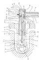
入子7が破損すると、キャビティ10内に高圧で圧入供給された高温の湯、即ち溶融されたアルミニウム等の成形材料が、破損部分7aから入子7に形成された冷却穴9内に進入する。冷却穴9内に進入した湯は冷却パイプ11と供給パイプ41との間に形成された冷却水戻し通路43内に進入し、バルブブロック31の前面33を押圧する。その湯の圧力によってバルブブロック31はストッパ19側に押しやられ、バルブブロック31の移動によって係止部35を押圧されていたボール22がスプリング24の付勢に抗して押しやられてバルブブロック収容部14の内周面14a内から退避してバルブ保持手段21による拘束が解除され、図3に示すように後面34がストッパ19に当接する後退位置までバルブブロック収容部14内を摺動移動する。
When the
後退位置までバルブブロック31が移動して停止すると、バルブブロック31に穿設された冷却水供給孔36の入口36a及び冷却水戻し孔37の出口37bがバルブブロック収容部14の内周面14aによって遮断され、キャビティ10内から冷却穴9内に進入した湯は冷却パイプ11内で進入が止められる。よって可動型5の裏面8側への湯吹きが防止できると共に、冷却水導入パイプ16及び冷却水回収パイプ17側に湯が進入することなく、冷却水導入パイプ16や冷却水回収パイプ17の破損が防止できる。
When the
従って、入子7の破損に伴って、キャビティ10内に圧入された湯が冷却穴9内に進入しても入子7の破損或いは入子7及び入子7に設けられた冷却パイプ11等の極めて小範囲の破損に抑制することができ、入子7の破損に伴う補修が、入子7の交換修理、或いは入子7及び冷却パイプ11等の交換修理等の極めて容易な補修作業によって行え、補修コストの削減及び大幅な補修期間の短縮が可能になる。
Therefore, even if the hot water press-fitted into the
なお、本発明は上記実施の形態に限定されることなく、発明の趣旨を逸脱しない範囲で種々変更可能である。例えば上記実施の形態では可動型5に入子7を設けた金型1を例に説明したが、固定型2に入子7を設けた金型に上記構成を適用することもできる。また、上記実施の形態では冷却穴9が形成された入子7を備えた金型1を例に説明したが、詳細な説明を省略するが入子7に代えて冷却穴が形成されたピンを備えた金型の冷却構造においても同様の構成を採用することにより同様の作用効果を得ることができる。
In addition, this invention is not limited to the said embodiment, A various change is possible in the range which does not deviate from the meaning of invention. For example, in the above-described embodiment, the mold 1 in which the movable mold 5 is provided with the
1 金型
2 固定型
3 キャビティサイド
5 可動型
6 キャビティサイド
7 入子
8 裏面
9 冷却穴
10 キャビティ
11 冷却パイプ
14 バルブブロック収容部
14a 内周面
14b 冷却水導入口
14c 冷却水排出口
16 冷却水導入パイプ
17 冷却水回収パイプ
19 ストッパ
21 バルブ保持手段
31 バルブブロック
32 外周面
33 前面
34 後面
36 冷却水供給孔
36a 入口
36b 出口
37 冷却水戻し孔
37a 入口
37b 出口
41 供給パイプ
41a 先端
42 冷却水供給路
43 冷却水戻し路
I 冷却水供給通路
II 冷却水回収通路
DESCRIPTION OF SYMBOLS 1
Claims (6)
上記冷却穴に接続されて上記入子の裏面から突出する冷却パイプと、
上記入子の裏面から突出する上記冷却パイプの基端側に形成されたバルブブロック収容部と、
該バルブブロック収容部内に通常位置と後退位置との間で摺動可能に収容されたバルブブロックとを有し、
上記バルブブロックが通常位置において上記冷却パイプ及びバルブブロックを経て冷却水供給源からの冷却水を上記冷却穴に供給する冷却水供給通路及び冷却穴から冷却水を回収する冷却水回収通路が形成される一方、上記入子の破損に伴うキャビティ内から冷却穴へ進入する成形材料の圧力で上記バルブブロックが後退位置に移動して上記冷却水供給通路及び冷却水回収通路が遮蔽することを特徴とする金型冷却構造。 A fixed mold or movable mold is provided and has a nest protruding into the cavity, and cooling water is supplied to and recovered from a bottomed cooling hole formed in the nest and opened on the back surface of the nest. In the mold cooling structure for cooling
A cooling pipe connected to the cooling hole and projecting from the back surface of the nest;
A valve block housing portion formed on the base end side of the cooling pipe protruding from the back surface of the nest;
A valve block accommodated in the valve block accommodating portion so as to be slidable between a normal position and a retracted position;
A cooling water supply passage for supplying cooling water from a cooling water supply source to the cooling hole through the cooling pipe and the valve block and a cooling water recovery passage for collecting the cooling water from the cooling hole are formed at the normal position of the valve block. On the other hand, the valve block is moved to the retracted position by the pressure of the molding material entering the cooling hole from the cavity due to breakage of the insert, and the cooling water supply passage and the cooling water recovery passage are shielded. Mold cooling structure.
上記冷却穴に接続されて上記入子の裏面から突出する冷却パイプと、
上記入子の裏面から突出する上記冷却パイプの基端側に形成された冷却水導入口及び冷却水排出口が開口するバルブブロック収容部と、
該バルブブロック収容部内に通常位置と後退位置との間で摺動可能に収容されて冷却水供給孔及び冷却水戻し孔が形成されたバルブブロックとを有し、
上記バルブブロックが通常位置において上記冷却水供給孔によって上記冷却水導入口と冷却穴が連通して冷却水供給源からの冷却水を上記冷却穴に供給する冷却水供給通路を形成し、かつ冷却水戻し孔によって上記冷却穴と冷却水排出口が連通して冷却穴から冷却水を回収する冷却水回収通路を形成する一方、上記入子の破損に伴うキャビティ内から冷却穴へ進入する成形材料の圧力でバルブブロックが後退位置に移動して上記冷却水供給通路及び冷却水回収通路が遮蔽することを特徴とする金型冷却構造。 A fixed mold or movable mold is provided and has a nest protruding into the cavity, and cooling water is supplied to and recovered from a bottomed cooling hole formed in the nest and opened on the back surface of the nest. In the mold cooling structure for cooling
A cooling pipe connected to the cooling hole and projecting from the back surface of the nest;
A valve block housing portion in which a cooling water introduction port and a cooling water discharge port formed on the base end side of the cooling pipe projecting from the back surface of the insert are opened;
A valve block that is slidably housed between a normal position and a retracted position in the valve block housing portion and has a cooling water supply hole and a cooling water return hole formed therein,
When the valve block is in a normal position, the cooling water inlet and the cooling hole communicate with each other through the cooling water supply hole to form a cooling water supply passage for supplying the cooling water from the cooling water supply source to the cooling hole, and Molding material that enters the cooling hole from the cavity due to breakage of the insert while the cooling hole and the cooling water discharge port communicate with each other by the water return hole to form a cooling water recovery passage that collects the cooling water from the cooling hole The mold block cooling structure is characterized in that the valve block is moved to the retracted position by the pressure of and the cooling water supply passage and the cooling water recovery passage are shielded.
上記バルブブロックは、上記内周面に摺動可能に嵌合する外周面及び冷却穴内に対向する前面を有する円柱状で上記冷却水供給孔の入口及び冷却水戻し孔の出口がそれぞれ外周面に開口し冷却水供給孔の出口及び冷却水戻し孔の入口が前面に開口し、
上記バルブブロックが通常位置において冷却水供給孔の入口及び冷却水戻し孔の出口がそれぞれ冷却水導入口及び冷却水排出口と連通し、後退位置において冷却水供給孔の入口及び冷却水戻し孔の出口がそれぞれバルブブロック収容部の内周面で遮蔽されることを特徴とする請求項2に記載の金型冷却構造。 The valve block accommodating portion has a cylindrical shape having an inner peripheral surface, and the cooling water inlet and the cooling water outlet are opened on the peripheral wall.
The valve block has a cylindrical shape having an outer peripheral surface slidably fitted to the inner peripheral surface and a front surface facing the cooling hole, and an inlet of the cooling water supply hole and an outlet of the cooling water return hole are respectively provided on the outer peripheral surface. Open the outlet of the cooling water supply hole and the inlet of the cooling water return hole to the front,
When the valve block is in the normal position, the inlet of the cooling water supply hole and the outlet of the cooling water return hole communicate with the cooling water introduction port and the cooling water discharge port, respectively, and in the retracted position, the inlet of the cooling water supply hole and the cooling water return hole 3. The mold cooling structure according to claim 2, wherein the outlets are respectively shielded by the inner peripheral surface of the valve block housing portion.
Priority Applications (1)
| Application Number | Priority Date | Filing Date | Title |
|---|---|---|---|
| JP2004113402A JP2005296972A (en) | 2004-04-07 | 2004-04-07 | Mold cooling structure |
Applications Claiming Priority (1)
| Application Number | Priority Date | Filing Date | Title |
|---|---|---|---|
| JP2004113402A JP2005296972A (en) | 2004-04-07 | 2004-04-07 | Mold cooling structure |
Publications (1)
| Publication Number | Publication Date |
|---|---|
| JP2005296972A true JP2005296972A (en) | 2005-10-27 |
Family
ID=35329154
Family Applications (1)
| Application Number | Title | Priority Date | Filing Date |
|---|---|---|---|
| JP2004113402A Pending JP2005296972A (en) | 2004-04-07 | 2004-04-07 | Mold cooling structure |
Country Status (1)
| Country | Link |
|---|---|
| JP (1) | JP2005296972A (en) |
Cited By (13)
| Publication number | Priority date | Publication date | Assignee | Title |
|---|---|---|---|---|
| KR100874976B1 (en) | 2007-08-30 | 2008-12-19 | 한국단자공업 주식회사 | Cooling device of mold assembly |
| KR101119344B1 (en) * | 2011-05-09 | 2012-03-06 | 주식회사 윤일정밀 | The core insert-method cooling-equipment of plastic injection molding |
| JP2013158805A (en) * | 2012-02-06 | 2013-08-19 | Suguro Tekko:Kk | Cooling pipe for dies |
| JP2014136243A (en) * | 2013-01-17 | 2014-07-28 | Mazda Motor Corp | Die-casting metal mold structure |
| KR101499438B1 (en) * | 2009-04-09 | 2015-03-06 | 현대자동차 주식회사 | Apparatus for cooling of die-casting mold |
| KR101726723B1 (en) * | 2015-11-17 | 2017-04-13 | (주)유성 | Equipment for clinker removing of combustion chamber with cooler |
| CN109332646A (en) * | 2018-12-14 | 2019-02-15 | 宁波隆源精密机械有限公司 | A kind of gas-vapor mix cooling structure of die casting |
| CN109454215A (en) * | 2019-01-07 | 2019-03-12 | 盐城泰欧昌机械有限公司 | A kind of melting cup of die casting machine uniformly cooled down |
| CN109822830A (en) * | 2019-03-27 | 2019-05-31 | 河北铁科翼辰新材科技有限公司 | A kind of gauge apron injection mold mold core and edge column |
| CN112024829A (en) * | 2020-09-30 | 2020-12-04 | 中信戴卡股份有限公司 | Water-cooling mold |
| CN113306085A (en) * | 2021-05-17 | 2021-08-27 | 珠海格力精密模具有限公司 | Pen cap forming die structure |
| CN114309532A (en) * | 2021-11-26 | 2022-04-12 | 芜湖禾田汽车工业有限公司 | Die-casting die for aluminum alloy damping tower |
| KR102708148B1 (en) * | 2023-12-13 | 2024-09-20 | 구자갑 | Hole parts priority cooling mold system |
-
2004
- 2004-04-07 JP JP2004113402A patent/JP2005296972A/en active Pending
Cited By (15)
| Publication number | Priority date | Publication date | Assignee | Title |
|---|---|---|---|---|
| KR100874976B1 (en) | 2007-08-30 | 2008-12-19 | 한국단자공업 주식회사 | Cooling device of mold assembly |
| KR101499438B1 (en) * | 2009-04-09 | 2015-03-06 | 현대자동차 주식회사 | Apparatus for cooling of die-casting mold |
| KR101119344B1 (en) * | 2011-05-09 | 2012-03-06 | 주식회사 윤일정밀 | The core insert-method cooling-equipment of plastic injection molding |
| JP2013158805A (en) * | 2012-02-06 | 2013-08-19 | Suguro Tekko:Kk | Cooling pipe for dies |
| JP2014136243A (en) * | 2013-01-17 | 2014-07-28 | Mazda Motor Corp | Die-casting metal mold structure |
| KR101726723B1 (en) * | 2015-11-17 | 2017-04-13 | (주)유성 | Equipment for clinker removing of combustion chamber with cooler |
| CN109332646A (en) * | 2018-12-14 | 2019-02-15 | 宁波隆源精密机械有限公司 | A kind of gas-vapor mix cooling structure of die casting |
| CN109454215A (en) * | 2019-01-07 | 2019-03-12 | 盐城泰欧昌机械有限公司 | A kind of melting cup of die casting machine uniformly cooled down |
| CN109822830A (en) * | 2019-03-27 | 2019-05-31 | 河北铁科翼辰新材科技有限公司 | A kind of gauge apron injection mold mold core and edge column |
| CN109822830B (en) * | 2019-03-27 | 2024-03-29 | 河北铁科翼辰新材科技有限公司 | Gauge baffle injection mold core and insert column |
| CN112024829A (en) * | 2020-09-30 | 2020-12-04 | 中信戴卡股份有限公司 | Water-cooling mold |
| CN113306085A (en) * | 2021-05-17 | 2021-08-27 | 珠海格力精密模具有限公司 | Pen cap forming die structure |
| CN114309532A (en) * | 2021-11-26 | 2022-04-12 | 芜湖禾田汽车工业有限公司 | Die-casting die for aluminum alloy damping tower |
| CN114309532B (en) * | 2021-11-26 | 2024-04-26 | 芜湖禾田汽车工业有限公司 | Aluminum alloy shock tower die casting mold |
| KR102708148B1 (en) * | 2023-12-13 | 2024-09-20 | 구자갑 | Hole parts priority cooling mold system |
Similar Documents
| Publication | Publication Date | Title |
|---|---|---|
| JP2005296972A (en) | Mold cooling structure | |
| JP5684225B2 (en) | Spout sleeve | |
| JP2009050855A (en) | Casting apparatus and casting method | |
| JP6231836B2 (en) | Injection mold | |
| CN110248793B (en) | Molding die | |
| JP5011271B2 (en) | Core pin | |
| JP2003231165A (en) | Mold | |
| JP2016107286A (en) | Slide pin cooling device | |
| JP4847782B2 (en) | Mold injection mold | |
| JP4869990B2 (en) | Injection mold and injection molding method using the same | |
| JP2007229782A (en) | Pin locking device | |
| JP4474397B2 (en) | Injection mold equipment | |
| JP2010234541A (en) | Mold device having hot runner | |
| US12036603B2 (en) | Casting mold | |
| JP2003220633A (en) | Molding equipment for molding | |
| JP4818733B2 (en) | Die casting plunger | |
| JP3713707B2 (en) | Mold equipment for molding | |
| JP7382619B2 (en) | Casting mold manufacturing equipment | |
| JP2006192754A (en) | Molding mold for resin lens | |
| JP3532107B2 (en) | Nozzle for vacuum die casting machine | |
| KR20080081463A (en) | Injection sleeve cooling system for die casting | |
| JP2005280002A (en) | Mold assembly, molded product, molding method thereof and molding machine | |
| JP3987453B2 (en) | Hot runner nozzle mounting structure | |
| JP2010089390A (en) | Molding die | |
| JP2007196640A (en) | Resin injection mold |