JP2005296936A - Ceramic honeycomb filter and exhaust gas cleaning apparatus - Google Patents
Ceramic honeycomb filter and exhaust gas cleaning apparatus Download PDFInfo
- Publication number
- JP2005296936A JP2005296936A JP2005036802A JP2005036802A JP2005296936A JP 2005296936 A JP2005296936 A JP 2005296936A JP 2005036802 A JP2005036802 A JP 2005036802A JP 2005036802 A JP2005036802 A JP 2005036802A JP 2005296936 A JP2005296936 A JP 2005296936A
- Authority
- JP
- Japan
- Prior art keywords
- exhaust gas
- ceramic honeycomb
- honeycomb filter
- outflow side
- partition wall
- Prior art date
- Legal status (The legal status is an assumption and is not a legal conclusion. Google has not performed a legal analysis and makes no representation as to the accuracy of the status listed.)
- Pending
Links
Images

Landscapes
- Processes For Solid Components From Exhaust (AREA)
- Filtering Materials (AREA)
- Filtering Of Dispersed Particles In Gases (AREA)
- Exhaust Gas Treatment By Means Of Catalyst (AREA)
Abstract
Description
本発明は、ディーゼルエンジンの排気ガス中の粒子状物質を捕集、浄化するセラミックハニカムフィルタ及び排気ガス浄化装置に関する。 The present invention relates to a ceramic honeycomb filter and an exhaust gas purification device for collecting and purifying particulate matter in exhaust gas of a diesel engine.
近年、ディーゼルエンジンの排気ガス中から粒子状物質を除去するため、セラミックハニカム構造体の複数の流路を両端部で交互に目封止したセラミックハニカムフィルタが使用されるようになってきた。 In recent years, a ceramic honeycomb filter in which a plurality of flow paths of a ceramic honeycomb structure are alternately plugged at both ends has been used in order to remove particulate matter from exhaust gas of a diesel engine.
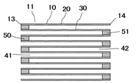
通常、セラミックハニカムフィルタは、図1に示すように、外周壁20と、この外周壁の内周側で隔壁30により囲まれた多数の流路を有する多孔質セラミックハニカム構造体10の排気ガス流入側端面、及び流出側端面で、所望の流路が交互に目封止されている。
ハニカムフィルタに流入した排気ガスは、排気ガス流入側端面13に開口した流路41からハニカムフィルタ内に侵入し、隔壁に形成された細孔内(図示せず)を通過して、隣接する排気ガス流出側端面14に開口した流路42から排出される。この隔壁に形成された細孔は例えば平均細孔径で10〜40μmのものなどが知られている。このとき、排気ガス中に含まれる粒子状物質などは、隔壁表面や隔壁内部に形成された細孔に捕集され、排気ガスが浄化される。従って、このセラミックハニカムフィルタの特性に関しては、微粒子の捕集効率が高いこと、圧力損失が低いこと、という相反する特性を満足させることが要求されている。
Normally, as shown in FIG. 1, the ceramic honeycomb filter has an
Exhaust gas that has flowed into the honeycomb filter enters the honeycomb filter from the
この細孔に捕集された粒子状物質が一定量以上になると細孔の目詰まりが発生して、ハニカムフィルタの圧力損失が上昇し、エンジンの出力低下につながり好ましくないため、バーナーや電気ヒーターにより捕集された粒子状物質を燃焼させ、ハニカムフィルタの再生が行われる。この時、捕集された粒子状物質が多い程、ハニカムフィルタ内の温度を均一に制御することが困難であり、特に高濃度に粒子状物質が堆積した箇所の温度が上昇し易く、燃焼に伴い発生する熱応力によりハニカムフィルタが破損することがあった。また、場合によっては隔壁を構成するセラミック材料の溶融温度以上にハニカムフィルタの温度が上昇し、隔壁に溶損が発生するという問題もあった。一方、ハニカムフィルタの最高温度を、破損や、溶損が起きないように抑えようとすると、粒子状物質の燃え残りが発生し、燃え残り粒子状物質により、再生処理を行ってもハニカムフィルタの圧力損失を低減することができないという問題があった。 If the amount of particulate matter collected in the pores exceeds a certain level, clogging of the pores occurs and the pressure loss of the honeycomb filter increases, leading to a decrease in engine output. The particulate matter collected by is burned, and the honeycomb filter is regenerated. At this time, the more particulate matter collected, the more difficult it is to control the temperature in the honeycomb filter uniformly, and the temperature of the portion where the particulate matter is deposited at a high concentration is likely to rise, resulting in combustion. The honeycomb filter may be damaged due to the thermal stress generated. In some cases, the temperature of the honeycomb filter rises above the melting temperature of the ceramic material constituting the partition walls, and there is a problem that the partition walls are melted. On the other hand, if the maximum temperature of the honeycomb filter is suppressed so as not to break or melt, particulate matter remains unburned. There was a problem that pressure loss could not be reduced.
このような問題を解決するため、特許文献1に記載されている発明では、排気系の上流に酸化触媒、その下流に粒子状物質捕集用のフィルタとを配置し、上流側の酸化触媒で排気ガス中のNO(一酸化窒素)を酸化してNO2 (二酸化窒素)を生成し、下流のフィルタで排気ガス中の粒子状物質を捕集するとともに、この捕集された粒子状物質を前記酸化触媒で生成したNO2 を用いて燃焼させることにより、フィルタ上の粒子状物質を除去するディーゼル排ガスの微粒子除去方法とその装置が開示されている。この技術によれば、例えば225℃から300℃などの低温下でもフィルタに集積されている粒子状物質を効果的に燃焼させ、それによって、従来技術ではフィルタに集積された粒子状物質が原因で生じる背圧を低減させる効果があるとしている。 In order to solve such a problem, in the invention described in Patent Document 1, an oxidation catalyst is disposed upstream of the exhaust system, and a filter for collecting particulate matter is disposed downstream thereof. NO (nitrogen monoxide) in the exhaust gas is oxidized to produce NO 2 (nitrogen dioxide), and the particulate matter in the exhaust gas is collected by the downstream filter, and the collected particulate matter is collected. Disclosed is a diesel exhaust particulate removal method and apparatus for removing particulate matter on a filter by burning using NO 2 generated by the oxidation catalyst. According to this technology, particulate matter accumulated in the filter is effectively burned even at a low temperature, for example, 225 ° C. to 300 ° C., thereby causing the particulate matter accumulated in the filter in the prior art. It is said that there is an effect of reducing the generated back pressure.
また、特許文献2に記載の発明では、隔壁表面に担持した白金族金属及びアルカリ土類金属酸化物を含んでなる触媒の作用により粒子状物質の燃焼が始まる温度を低下させ、この粒子状物質を連続的に除去するディ−ゼル排気粒子用フィルタが開示されている。このフィルタによれば、ディーゼルエンジンの作動条件下で得られる排気ガス温度程度の低い温度条件であっても例えばセラミックハニカム構造体から成るフィルタ中に蓄積した粒子をフィルタの損傷する危険無しに除去することができるとしている。 In the invention described in Patent Document 2, the temperature at which the particulate matter starts to burn is lowered by the action of a catalyst comprising a platinum group metal and an alkaline earth metal oxide supported on the partition wall surface. A diesel exhaust particulate filter that continuously removes water is disclosed. According to this filter, particles accumulated in, for example, a filter made of a ceramic honeycomb structure can be removed without risk of damage to the filter even under low temperature conditions such as exhaust gas temperatures obtained under diesel engine operating conditions. You can do that.
いずれの上記従来技術においても、触媒物質の作用により、セラミックハニカムフィルタ上での粒子状物質の燃焼を低温で且つ良好に行うことにより、排気ガス中の粒子状物質を除去すると共にセラミックハニカムフィルタの溶損を防ぐ技術が提案されている。 In any of the above prior arts, the particulate matter in the exhaust gas is removed and the ceramic honeycomb filter is removed by performing the combustion of the particulate matter on the ceramic honeycomb filter at a low temperature and favorably by the action of the catalyst substance. Technologies for preventing melting damage have been proposed.
しかしながら、従来技術のセラミックハニカムフィルタを、上記特許文献記載のディーゼル排気ガスの微粒子除去装置やディーゼル排気粒子用フィルタに適用してディーゼルエンジンからの排気ガスを浄化しようとした場合、排気ガス中の粒子状物質の大半は、除去できるものの、完全に除去することは難しく、有害な粒子状物質が僅かに排出されるという問題を抱えていた。すなわち、ディーゼルエンジンの排気ガス中に含まれる粒子状物質は、主として燃料、潤滑油の不完全燃焼により生成するカーボンからなる煤、未燃焼の燃料分、潤滑油分であるSOF(Soluble Organic Fraction;可溶性有機成分)、燃料中の硫黄分が酸化されミスト状硫酸塩として排出される微量のサルフェートから成っているが、その粒径は主にナノメートルオーダーであることから、従来技術のセラミックハニカムフィルタの隔壁に形成された平均細孔径10〜40μmの細孔では、粒子状物質全てを捕集することは困難であり、更なる捕集率の向上が望まれていた。 However, when the ceramic honeycomb filter of the prior art is applied to the diesel exhaust gas particulate removal device or diesel exhaust particle filter described in the above-mentioned patent document to purify the exhaust gas from the diesel engine, the particles in the exhaust gas Although most of the particulate matter can be removed, it is difficult to remove completely, and there is a problem that a little harmful particulate matter is discharged. That is, the particulate matter contained in the exhaust gas of the diesel engine is mainly composed of fuel, carbon generated by incomplete combustion of the lubricating oil, unburned fuel, and SOF (Solid Organic Fraction) as the lubricating oil; Soluble organic components), and a small amount of sulfate that is oxidized as sulfur in the fuel and discharged as a mist-like sulfate. Its particle size is mainly on the order of nanometers. In the pores having an average pore diameter of 10 to 40 μm formed in the partition walls, it is difficult to collect all the particulate matter, and further improvement in the collection rate has been desired.
したがって、本発明の目的は、多孔質セラミックハニカム構造体の流路を目封止することによりハニカム構造体の隔壁に形成された細孔に排気ガスを通過させる構造のセラミックハニカムフィルタを使用した場合における上記問題を解決して、圧力損失を大きく上昇させることなく、粒子状物質の排出量をより低減することができるセラミックハニカムフィルタ、及び排気ガス浄化装置を提供することにある。 Therefore, an object of the present invention is to use a ceramic honeycomb filter having a structure in which exhaust gas is allowed to pass through pores formed in the partition walls of the honeycomb structure by plugging the flow path of the porous ceramic honeycomb structure. It is an object of the present invention to provide a ceramic honeycomb filter and an exhaust gas purification device that can further reduce the discharge amount of particulate matter without greatly increasing the pressure loss.
本発明のセラミックハニカムフィルタは、多孔質セラミックハニカム構造体の流路を目封止することによりハニカム構造体の隔壁に形成された細孔に排気ガスを通過させる構造のセラミックハニカムフィルタにおいて、少なくとも排気ガス流出側目封止部の一部がセラミックハニカムフィルタの排気ガス流出側端面より離れて配置されていることを特徴とする。 The ceramic honeycomb filter of the present invention is a ceramic honeycomb filter having a structure in which exhaust gas is allowed to pass through pores formed in partition walls of a honeycomb structure by plugging a flow path of the porous ceramic honeycomb structure. A part of the gas outflow side plugging portion is disposed away from the exhaust gas outflow side end surface of the ceramic honeycomb filter.
本発明のセラミックハニカムフィルタにおいて、前記排気ガス流出側目封止部より排気ガス流出側の隔壁の少なくとも一部に吸着剤が担持されていることが好ましい。また、本発明のセラミックハニカムフィルタにおいて、前記排気ガス流出側目封止部より排気ガス流出側の隔壁の少なくとも一部に触媒物質が担持されていることが好ましい。 In the ceramic honeycomb filter of the present invention, it is preferable that an adsorbent is supported on at least a part of the partition wall on the exhaust gas outflow side from the exhaust gas outflow side plugging portion. In the ceramic honeycomb filter of the present invention, it is preferable that a catalyst material is supported on at least a part of the partition wall on the exhaust gas outflow side from the exhaust gas outflow side plugged portion.
本発明のセラミックハニカムフィルタにおいて、前記排気ガス流出側目封止部より排気ガス流入側の隔壁の少なくとも一部に触媒物質が担持されていることが好ましい。 In the ceramic honeycomb filter of the present invention, it is preferable that a catalyst material is supported on at least a part of the partition wall on the exhaust gas inflow side from the exhaust gas outflow side plugging portion.
本発明のセラミックハニカムフィルタにおいて、前記セラミックハニカムフィルタの排気ガス流出側端面より離れて配置された排気ガス流出側目封止部の排気ガス流出側端面と、セラミックハニカムフィルタの排気ガス流出側端面との流路方向の間隔が、前記セラミックハニカムフィルタ全長の0.5倍以下であることが好ましい。 In the ceramic honeycomb filter of the present invention, the exhaust gas outflow side end surface of the exhaust gas outflow side plugging portion disposed away from the exhaust gas outflow side end surface of the ceramic honeycomb filter, and the exhaust gas outflow side end surface of the ceramic honeycomb filter It is preferable that the interval in the flow path direction is 0.5 times or less the total length of the ceramic honeycomb filter.
本発明のセラミックハニカムフィルタにおいて、前記セラミックハニカム構造体の隔壁の結晶相主成分がコーディエライトであり、気孔率が50〜80%であって、前記セラミックハニカム構造体の隔壁がFeを含むとともに、スピネルを含み、該スピネルの含有量はX線回折強度比にして4%以下であり、該スピネルの粒径は0.01〜5μmのものが含まれることが好ましい。 In the ceramic honeycomb filter of the present invention, the main component of the crystal phase of the partition walls of the ceramic honeycomb structure is cordierite, the porosity is 50 to 80%, and the partition walls of the ceramic honeycomb structure include Fe. The spinel content is preferably 4% or less in terms of the X-ray diffraction intensity ratio, and the spinel particle size is preferably 0.01 to 5 μm.
本発明のセラミックハニカムフィルタにおいて、前記スピネルのうち粒径が0.01〜5μmであるスピネルの個数割合が80%以上であることが好ましい。 In the ceramic honeycomb filter of the present invention, the number ratio of spinels having a particle diameter of 0.01 to 5 μm among the spinels is preferably 80% or more.
本発明のセラミックハニカムフィルタにおいて、前記スピネルに含有されるFeの濃度が、Fe2O3換算で0.1〜10質量%であることが好ましい。 In the ceramic honeycomb filter of the present invention, the concentration of Fe contained in the spinel is preferably 0.1 to 10% by mass in terms of Fe 2 O 3 .
本発明の排気ガス浄化装置は、多孔質セラミックハニカム構造体の流路を目封止することによりハニカム構造体の隔壁に形成された細孔に排気ガスを通過させる構造のセラミックハニカムフィルタと、その上流側に配置された排気ガスの温度を上昇させるための燃料添加装置とから構成され、前記セラミックハニカムフィルタは、少なくとも排気ガス流出側目封止部の一部がセラミックハニカムフィルタの排気ガス流出側端面より離れて配置され、前記排気ガス流出側目封止部より排気ガス流入側の隔壁の少なくとも一部に触媒物質が担持されると共に、前記排気ガス流出側目封止部より排気ガス流出側の隔壁の少なくとも一部に吸着剤及び/又は触媒物質が担持されていることを特徴とする。 An exhaust gas purification device of the present invention includes a ceramic honeycomb filter having a structure in which exhaust gas is passed through pores formed in partition walls of a honeycomb structure by plugging the flow path of the porous ceramic honeycomb structure, and And a fuel addition device for raising the temperature of the exhaust gas arranged upstream, wherein the ceramic honeycomb filter has at least a part of the exhaust gas outlet side plugging portion of the ceramic honeycomb filter. The catalyst material is supported on at least a part of the partition wall on the exhaust gas inflow side from the exhaust gas outflow side plugging portion, and is separated from the end surface, and the exhaust gas outflow side from the exhaust gas outflow side plugging portion An adsorbent and / or a catalyst substance is supported on at least a part of the partition walls.
次に、本発明の作用効果について説明する。
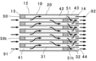
図2に模式断面図を示すように、本発明のセラミックハニカムフィルタ12は、多孔質セラミックハニカム構造体10の流路を目封止することによりハニカム構造体の隔壁31に形成された細孔に排気ガスを通過させる構造のセラミックハニカムフィルタであって、少なくとも排気ガス流出側目封止部51の一部がセラミックハニカムフィルタの排気ガス流出側端面14より離れて配置されている。ディーゼルエンジンからの排気ガス91は、排気ガス流入側端面13に開口した流路41から流入し、多孔質隔壁31中に形成された細孔(図示せず)を通過する際に排気ガス中の粒子状物質の大半が除去され、排気ガス流出側に開口した流路42に排出された後、排気ガス流出側に開口した流路のうち排気ガス流出側目封止部51より排気ガス流出側に配置された流路43を通過して排出される。このため、隔壁31を通過した排気ガス中に僅かに残存する微細な粒子状物質は、排気ガス流出側目封止部51より排気ガス流出側の隔壁32を利用して、例えば吸着剤或いは触媒物質等を担持させることにより、捕集或いは浄化される。このため多孔質セラミックハニカム構造体の所望の流路を両端部で目封止した従来技術のセラミックハニカムフィルタに比べて、粒子状物質の排出量を低減することができる。
Next, the function and effect of the present invention will be described.
As shown in the schematic cross-sectional view of FIG. 2, the
上記のような粒子状物質の排出量を低減させる作用効果は、従来技術の図1に示すセラミックハニカムフィルタの排気ガス流出側に、吸着剤或いは触媒物質等を担持させたストレートフロータイプのセラミックハニカム構造体を直列に配置させた構成としても具現不可能ではないが、このような構成とした場合、圧力損失が上昇したり、浄化性能が低下するという問題が発生する。即ち、セラミックハニカムフィルタの排気ガス流出側に吸着剤或いは触媒物質等を担持させたセラミックハニカム構造体を配置する際には、両者は脆性材料であるため、近接することができないことから、把持部材などを介して、両者の間に隙間を設けて流路方向に配置する必要があるため、排気ガスがセラミックハニカムフィルタから排出する際に発生する圧力損失、セラミックハニカム構造体に流入する際に発生する圧力損失により、排気ガス浄化装置の圧力損失が上昇するが、本発明のセラミックハニカムフィルタの場合、多孔質隔壁31を通過した排気ガスは、排気ガス流出側に開口した流路42から43へと直接流入することから、前記のような圧力損失は発生せず、排気ガス浄化装置の圧力損失を低く押さえることができるという効果を有している。また、セラミックハニカムフィルタの排気ガス流入側に燃料を添加し、多孔質隔壁31に捕集された粒子状物質を燃焼させる場合、或いは多孔質隔壁31に触媒物質を担持して触媒物質により粒子状物質を燃焼させる場合には、多孔質隔壁31を通過した高温となった排気ガスが、排気ガス流出側に開口した流路42から43へと直接高温となった状態で流入することから、排気ガス中に僅かに残存する微細な粒子状物質が、排気ガス流出側目封止部51より排気ガス流出側の隔壁32に担持された吸着剤或いは触媒物質等により、捕集或いは浄化される効果が大きくなる。
The effect of reducing the discharge amount of the particulate matter as described above is the straight flow type ceramic honeycomb in which an adsorbent or a catalytic substance is supported on the exhaust gas outflow side of the ceramic honeycomb filter shown in FIG. Although it is not impossible to implement a configuration in which the structures are arranged in series, such a configuration causes problems such as an increase in pressure loss and a decrease in purification performance. That is, when a ceramic honeycomb structure carrying an adsorbent or a catalyst substance is disposed on the exhaust gas outflow side of the ceramic honeycomb filter, since both are brittle materials, they cannot be brought close to each other. Because there is a need to provide a gap between the two via the flow path, etc., pressure loss that occurs when exhaust gas is discharged from the ceramic honeycomb filter, occurs when it flows into the ceramic honeycomb structure However, in the case of the ceramic honeycomb filter of the present invention, the exhaust gas that has passed through the
本発明のセラミックハニカムフィルタの場合、流出側目封止部51より排気ガス流出側の流路44の隔壁は気孔率が大きい多孔質体としているため、流路43を排気ガスが流れるときの流路43内の圧力上昇と、流路43よりフィルタ外へ流出した排気ガス92による流路44内の気体の吸出し効果による流路44内の圧力減少とにより、流路43と流路44との圧力差が生じ、このため流出側目封止部51より排気ガス流出側の隔壁32を排気ガスが通過し、この際、隔壁32内の細孔により微粒子状物質が捕集されると共に、流出側目封止部51より排気ガス流出側の流路44の隔壁32に担持された吸着剤或いは触媒物質などにより排気ガス中の微粒子状物質を更に捕集或いは浄化できる。更に一つのセラミックハニカムフィルタで対応できるので排気ガス浄化装置がコンパクトになるという効果も有している。
In the case of the ceramic honeycomb filter of the present invention, since the partition wall of the
ここで、排気ガス流出側目封止部は、全てのものがセラミックハニカムフィルタの排気ガス流出側端面より離れて配置されている必要はなく、排気ガス流出側目封止部のうち個数割合にして80%以上のものが、セラミックハニカムフィルタの排気ガス流出側端面より離れて配置されていれば良い。より好ましくは個数割合で90%以上である。 Here, the exhaust gas outflow side plugged portions do not necessarily have to be arranged apart from the exhaust gas outflow side end surface of the ceramic honeycomb filter. 80% or more may be disposed away from the end face on the exhaust gas outflow side of the ceramic honeycomb filter. More preferably, the number ratio is 90% or more.
本発明のセラミックハニカムフィルタにおいて、前記排気ガス流出側目封止部より排気ガス流出側の隔壁の少なくとも一部に吸着剤が担持されていることが好ましいのは、以下の理由による。排気ガスが排気ガス流出側目封止部51より排気ガス流入側の隔壁31を通過する際に、排気ガス中の粒子状物質の大半が、隔壁31の表面や隔壁31中の細孔に捕集されるのと共に、隔壁31を通過した排気ガス中に僅かに残存する主として微細な粒子状物質が、前記排気ガス流出側目封止部51より排気ガス流出側の隔壁32の少なくとも一部に担持された吸着剤により捕集されるため、従来技術のセラミックハニカムフィルタに比べ、粒子状物質の捕集効率を高くすることができ、粒子状物質の排出量を低減することができるからである。
In the ceramic honeycomb filter of the present invention, the adsorbent is preferably supported on at least a part of the partition wall on the exhaust gas outflow side from the exhaust gas outflow side plugging portion for the following reason. When the exhaust gas passes through the
このため、前記吸着剤は、粒子状物質を吸着可能な吸着剤であることが好ましく、高比表面積を有するアルミナ、ゼオライトを主成分とするものが好適に使用されるが、吸着性能を考慮するとゼオライトを主成分とすることが好ましい。ゼオライトはその結晶構造中に微細な細孔を有するアルミノケイ酸塩であり、この細孔中に微細な粒子状物質を吸着することができる。ゼオライトは、天然品、合成品のいずれでも良く、種類は特に限定されないが、粒子状物質の吸着性、耐熱性、耐久性の観点から、SiO2/Al2O3比の高いものが好適に用いられる。具体的にはZSM−5、MFI型ゼオライト、βゼオライト、モルデナイト、USY、フェリライト、A型ゼオライト、フォージャサイト、シリカライト、メタロシリケート等及びこれらの任意の組合せに係わるものを用いることができる。また、排気ガスが高温になった時に吸着材に吸着された粒子状物質の燃焼浄化を容易に行わせるため、同時に、排気ガス流出側目封止部より排気ガス流出側の隔壁の少なくとも一部に例えば白金族金属を含む触媒物質を担持しても良い。 For this reason, the adsorbent is preferably an adsorbent capable of adsorbing particulate matter, and those mainly composed of alumina and zeolite having a high specific surface area are preferably used. It is preferable to use zeolite as a main component. Zeolite is an aluminosilicate having fine pores in its crystal structure, and fine particulate matter can be adsorbed in the pores. The zeolite may be a natural product or a synthetic product, and the type is not particularly limited, but from the viewpoint of adsorbability, heat resistance, and durability of the particulate matter, those having a high SiO 2 / Al 2 O 3 ratio are preferable. Used. Specifically, those related to ZSM-5, MFI type zeolite, β zeolite, mordenite, USY, ferrilite, A type zeolite, faujasite, silicalite, metallosilicate, and any combination thereof can be used. . In addition, at the same time, at least a part of the partition wall on the exhaust gas outflow side from the exhaust gas outflow side plugging portion is used at the same time to facilitate the combustion purification of the particulate matter adsorbed on the adsorbent when the exhaust gas becomes high temperature. For example, a catalyst material containing a platinum group metal may be supported.
また、本発明のセラミックハニカムフィルタにおいて、前記排気ガス流出側目封止部より排気ガス流出側の隔壁の少なくとも一部に触媒物質が担持されていることが好ましいのは、以下の理由による。即ち、排気ガスが、排気ガス流出側目封止部より排気ガス流出側の隔壁31を通過する際に、排気ガス中の粒子状物質が、隔壁31の表面や隔壁31中の細孔に捕集されるのと共に、隔壁31を通過した排気ガス中に僅かに残存する主として微細な粒子状物質が、前記排気ガス流出側目封止部より排気ガス流出側の隔壁32の少なくとも一部に担持された触媒物質により燃焼浄化されるため、従来技術のセラミックハニカムフィルタに比べ、粒子状物質の浄化効率を高くすることができ、粒子状物質の排出量を低減することができる。
In the ceramic honeycomb filter of the present invention, the catalyst material is preferably supported on at least a part of the partition wall on the exhaust gas outflow side from the plugging portion on the exhaust gas outflow side for the following reason. That is, when the exhaust gas passes through the
このため、前記排気ガス流出側目封止部より排気ガス流出側の隔壁の少なくとも一部に担持される触媒物質は、例えば、Pt、Pd、Ru、Rh又はその組合せ等の白金族金属を含む触媒物質が好適であるが、アルカリ土類金属酸化物や希土類酸化物、或いはベース金属触媒、典型的にはランタン、セシウム、バナジウム(La/Cs/V2O3)類等を含んでも良い。また、公知のγアルミナ等の活性アルミナからなる高比表面積材料が含まれると、粒子状物質を吸着できるのと共に、触媒物質と排気ガスとの接触面積を大きくすることができ、排気ガスの浄化効率を高めることができることから好ましい。 For this reason, the catalyst material supported on at least a part of the partition on the exhaust gas outflow side from the exhaust gas outflow side plugging portion includes, for example, a platinum group metal such as Pt, Pd, Ru, Rh, or a combination thereof. Catalytic materials are preferred, but may include alkaline earth metal oxides, rare earth oxides, or base metal catalysts, typically lanthanum, cesium, vanadium (La / Cs / V 2 O 3 ), and the like. In addition, when a high specific surface area material made of activated alumina such as known γ-alumina is included, particulate matter can be adsorbed and the contact area between the catalyst substance and the exhaust gas can be increased, thereby purifying the exhaust gas. It is preferable because efficiency can be increased.
また、本発明のセラミックハニカムフィルタにおいて、前記排気ガス流出側目封止部より排気ガス流入側の隔壁の少なくとも一部に触媒物質が担持されていることが好ましい理由は以下による。前記排気ガス流出側目封止部51より排気ガス流入側の隔壁31の少なくとも一部に触媒物質が担持されていると、排気ガス中の粒子状物質はこの隔壁31に担持された触媒物質の作用により燃焼除去されるのと共に、排気ガス流出側目封止部51より排気ガス流出側に排出された後は、セラミックハニカム構造体中の流路43を通過してゆくことになる。このため、隔壁31を通過してきた排気ガス中に僅かに残存する微細な粒子状物質は、排気ガス流出側目封止部51より排気ガス流出側の隔壁32を利用して、例えば吸着剤或いは触媒物質等を担持させることにより、捕集或いは浄化される。このため多孔質セラミックハニカム構造体の所望の流路を両端部で目封止した従来技術のセラミックハニカムフィルタに比べて、粒子状物質の排出量を低減することができる。
In the ceramic honeycomb filter of the present invention, the reason why it is preferable that the catalyst material is supported on at least a part of the partition wall on the exhaust gas inflow side from the exhaust gas outflow side plugging portion is as follows. When a catalytic material is supported on at least a part of the
また、前記排気ガス流出側目封止部より排気ガス流入側の隔壁の少なくとも一部に担持された触媒物質は、例えば、Pt、Pd、Ru、Rh又はその組合せ等の、白金族金属を含む触媒物質が好適であるが、アルカリ土類金属酸化物や希土類酸化物、或いはベース金属触媒、典型的にはランタン、セシウム、バナジウム(La/Cs/V2O3)類等を含んでも良い。また、公知のγアルミナ等の活性アルミナからなる高比表面積材料が含まれると、触媒物質と排気ガスとの接触面積を大きくすることができ、排気ガスの浄化効率を高めることができることから好ましい。 Further, the catalyst material supported on at least a part of the partition wall on the exhaust gas inflow side from the exhaust gas outflow side plugging portion includes a platinum group metal such as Pt, Pd, Ru, Rh, or a combination thereof. Catalytic materials are preferred, but may include alkaline earth metal oxides, rare earth oxides, or base metal catalysts, typically lanthanum, cesium, vanadium (La / Cs / V 2 O 3 ), and the like. In addition, it is preferable that a high specific surface area material made of activated alumina such as known γ-alumina is included because the contact area between the catalyst substance and the exhaust gas can be increased and the purification efficiency of the exhaust gas can be increased.
本発明のセラミックハニカムフィルタにおいて、排気ガス流出側目封止部51より排気ガス流入側の隔壁31の少なくとも一部に触媒物質が担持され、且つ、排気ガス流出側の隔壁32の少なくとも一部に触媒物質が担持されている場合には、排気ガス流出側の隔壁32の少なくとも一部に担持された触媒物質の担持量を、排気ガス流入側の隔壁31の少なくとも一部に担持された触媒物質より、多くすることにより、隔壁31を通過してきた排気ガス中に僅かに残存する粒子状物質を、より効果的に燃焼浄化することが可能となる。或いは 排気ガス流出側の隔壁32の少なくとも一部に担持された触媒物質を、排気ガス流入側の隔壁31の少なくとも一部に担持された触媒物質より、低温で活性なものとすることにより、隔壁31を通過してきた排気ガス中に僅かに残存する粒子状物質を、より効果的に燃焼浄化することが可能となる。
In the ceramic honeycomb filter of the present invention, a catalyst material is supported on at least a part of the
本発明のセラミックハニカムフィルタにおいて、排気ガス流出側端面より離れて配置された排気ガス流出側目封止部の排気ガス流出側端面と、セラミックハニカムフィルタの排気ガス流出側端面との流路方向の間隔が、前記セラミックハニカムフィルタ全長の0.5倍以下であることが好ましいのは、排気ガス流出側目封止部の排気ガス流出側端面と、セラミックハニカムフィルタの排気ガス流出側端面との流路方向の間隔がセラミックハニカムフィルタ全長の0.5倍の長さの区間を越えると、セラミックハニカムフィルタの全長には制約があるため、排気ガス流出側目封止部より排気ガス流入側の隔壁の面積が少なくなるため、セラミックハニカムフィルタの初期圧力損失が上昇することもあるからである。また、排気ガス中の微細な粒子状物質を吸着する効果を得るためには、排気ガス流出側目封止部の排気ガス流出側端面と、セラミックハニカムフィルタの排気ガス流出側端面との流路方向の間隔が10mm以上であることが、より好ましい。また、更に好ましい排気ガス流出側目封止部の排気ガス流出側端面と、セラミックハニカムフィルタの排気ガス流出側端面との流路方向の間隔は、20mm以上、セラミックハニカムフィルタ全長の0.4倍以下である。 In the ceramic honeycomb filter of the present invention, the exhaust gas outflow side end surface of the exhaust gas outflow side plugging portion arranged away from the exhaust gas outflow side end surface and the exhaust gas outflow side end surface of the ceramic honeycomb filter in the flow direction The interval is preferably 0.5 times or less of the total length of the ceramic honeycomb filter. The distance between the exhaust gas outflow side end surface of the exhaust gas outflow side plugging portion and the exhaust gas outflow side end surface of the ceramic honeycomb filter is preferable. When the distance in the direction of the road exceeds the section of 0.5 times the total length of the ceramic honeycomb filter, the total length of the ceramic honeycomb filter is limited, so the partition wall on the exhaust gas inflow side from the plugging portion on the exhaust gas outflow side This is because the initial pressure loss of the ceramic honeycomb filter may be increased. Further, in order to obtain the effect of adsorbing fine particulate matter in the exhaust gas, the flow path between the exhaust gas outlet side end surface of the exhaust gas outlet side plugging portion and the exhaust gas outlet side end surface of the ceramic honeycomb filter More preferably, the interval in the direction is 10 mm or more. Further, the interval in the flow path direction between the exhaust gas outflow side end surface of the exhaust gas outflow side plugging portion and the exhaust gas outflow side end surface of the ceramic honeycomb filter is preferably 20 mm or more and 0.4 times the total length of the ceramic honeycomb filter. It is as follows.
また、本発明のセラミックハニカムフィルタにおいて、図3に示すように、少なくとも排気ガス流出側目封止部51の一部がセラミックハニカムフィルタの排気ガス流出側端面14より離れて配置されると共に、少なくとも排気ガス流入側目封止部50の一部が排気ガス流入側端面13より離れて配置されていると、より好ましい。この理由は、図2に示す構造のセラミックハニカムフィルタの場合、排気ガス流入側目封止部50の流入側端面50tに粒子状物質が堆積して、排気ガス流入側端面で開口している流路41の入口を狭めることによるセラミックハニカムフィルタの圧力損失の上昇が発生する場合もあり、少なくとも排気ガス流入側目封止部50の一部が排気ガス流入側端面13より離れて配置されていると、この現象を防げるからである。更に、図3に示す構造のセラミックハニカムフィルタにおいて、排気ガス流入側目封止部50より排気ガス流入側隔壁33の少なくとも一部に触媒物質が担持されていると、排気ガス流入側隔壁33で囲まれた流路を排気ガスが通過する際に、触媒物質の作用により高温化されることから、排気ガス流入側目封止部50と排気ガス流出側目封止部51との間の隔壁での、粒子状物質の燃焼浄化が容易になるため好ましい。また、粒子状物質の燃焼を更に容易に行わせるため、排気ガス流入側目封止部50と排気ガス流出側目封止部51との間の隔壁の少なくとも一部に触媒物質を担持しても良い。更には、粒子状物質の排出量を低減するために、排気ガス流出側目封止部51より排気ガス流出側の隔壁に吸着剤を担持しても良いし、触媒物質を担持しても良い。
Further, in the ceramic honeycomb filter of the present invention, as shown in FIG. 3, at least a part of the exhaust gas outlet
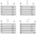
本発明の、セラミックハニカムフィルタの特徴は排気ガス流出側目封止部51の一部が排気ガス流出側端面14から離れて配置されていることであり、微細な粒子状物質を捕集するための排気ガス流出側目封止部より排気ガス流出側の隔壁32を存在させていればよく、図4(a)に示すように目封止部の長さは均一である必要はなく、図4(b)に示すように目封止端面51tの流出側端面からの距離が均一である必要もなく、図4(c)に示すように目封止部端面の形態が凸形状であっても、凹形状であっても構わない。また図4(d)に示すように、外周付近の流路では、排気ガス流出側目封止部をセラミックハニカムフィルタの排気ガス流出側端面から離れて配置する必要もなく、外周付近の流路では、目封止部が両端部に存在しても良い。これは、セラミックハニカムフィルタの外周に近い流路には、排気ガスが流通しにくいため、排気ガス流出側目封止部を排気ガス流出側端面より離れて配置した本発明の効果が小さいからである。
A feature of the ceramic honeycomb filter of the present invention is that a part of the exhaust gas outflow
本発明のセラミックハニカムフィルタにおいて、前記セラミックハニカム構造体の隔壁の結晶相主成分がコーディエライトであり、気孔率が50〜80%であって、前記セラミックハニカム構造体の隔壁がFeを含むとともに、スピネルを含み、該スピネルの含有量はX線回折強度比にして4%以下であり、該スピネルの粒径は0.01〜5μmのものが含まれることが好ましいのは、以下の理由による。本発明に用いられる多孔質セラミックハニカム構造体の隔壁を構成する材料としては、本発明が主にディーゼルエンジンの排気ガス中の微粒子を除去するためのフィルタとして使用されるため、耐熱性に優れた、コーディエライト、アルミナ、ムライト、窒化珪素、炭化珪素、チタン酸アルミニウム及びLASからなる群から選ばれた少なくとも1種を主結晶とするセラミック材料を用いることができるが、特にセラミックハニカムハニカム構造体の隔壁の結晶相主成分をコーディエライトとした場合は、低熱膨張特性が得られることから、熱衝撃に強いセラミックハニカムフィルタが得られる。ただし、本件発明のセラミックハニカムフィルタに圧力損失を小さくするため、隔壁の気孔率は50〜80%の高気孔率が必要となり、特に流路43から流路44へ排気ガスが通過しやすくするために、隔壁32は62〜80%の高気孔率が好ましいため、かかる高気孔率を得ようとすると、製造過程で造孔剤を多量に添加する必要が有り、コーディエライト結晶の配向性が乱され、熱膨張係数が大きくなる場合がある。しかしながら、本発明のセラミックハニカムフィルタにおいては、セラミックハニカム構造体の隔壁がFeを含むとともに、スピネルを含み、該スピネルの含有量はX線回折強度比にして4%以下であり、該スピネルの粒径は0.01〜5μmのものが含まれるようにしていることから、コーディエライト化原料であるカオリン、タルク中に存在するFeに起因して不可避的にセラミックハニカム構造体中に存在するFeが、スピネル中に高濃度、例えば、Fe2O3に換算して、(スピネル中のFe2O3濃度)/(コーディエライト結晶中のFe2O3濃度)≧1.1で存在するようになり、相対的にコーディエライト結晶中のFe濃度が低くなってコーディエライト結晶の熱膨張係数を小さくすることができ、セラミックハニカム構造体の熱膨張係数を低下させることができる。ここで、(スピネル中のFe2O3濃度)/(コーディエライト結晶中のFe2O3濃度)≦15が好ましい。(スピネル中のFe2O3濃度)/(コーディエライト結晶中のFe2O3濃度)が15超えると、スピネル自体の熱膨張係数が大きくなり、セラミックハニカム構造体の熱膨張係数が高くなることもあるからである。更に好ましい(スピネル中のFe2O3濃度)/(コーディエライト結晶中のFe2O3濃度)の範囲は3〜10である。
In the ceramic honeycomb filter of the present invention, the main component of the crystal phase of the partition walls of the ceramic honeycomb structure is cordierite, the porosity is 50 to 80%, and the partition walls of the ceramic honeycomb structure include Fe. The spinel content is 4% or less in terms of X-ray diffraction intensity ratio, and the spinel particle size is preferably 0.01 to 5 μm because of the following reasons . As a material constituting the partition walls of the porous ceramic honeycomb structure used in the present invention, the present invention is mainly used as a filter for removing fine particles in exhaust gas of a diesel engine, and thus has excellent heat resistance. Ceramic material having at least one main crystal selected from the group consisting of cordierite, alumina, mullite, silicon nitride, silicon carbide, aluminum titanate and LAS can be used. When cordierite is used as the main component of the crystal phase of the partition walls, low thermal expansion characteristics can be obtained, so that a ceramic honeycomb filter resistant to thermal shock can be obtained. However, in order to reduce the pressure loss in the ceramic honeycomb filter of the present invention, the partition wall must have a high porosity of 50 to 80%. In particular, the exhaust gas easily passes from the
ここで、スピネルとはMgO・Al2O3の組成を有するスピネル型構造の複酸化物結晶のことを言うが、本発明ではFe及び不可避不純物を含有している。そして、セラミックハニカム構造体の隔壁がスピネルを含むとは、X線回折図形において、コーディエライト(5SiO2・2Al2O3・2MgO)の回折ピーク及びスピネルの回折ピークに相当する回折角に回折ピークが認められる場合のことを言う。X線回折強度の測定は、セラミックハニカム構造体を微粉砕した後、目開き径1μmの篩により粒度調整し、粉末X線回折法で行った。 Here, the spinel refers to a double oxide crystal having a spinel structure having a composition of MgO.Al 2 O 3. In the present invention, the spinel contains Fe and inevitable impurities. In addition, the fact that the partition walls of the ceramic honeycomb structure include spinel means that the X-ray diffraction pattern is diffracted into a diffraction angle corresponding to a diffraction peak of cordierite (5SiO 2 .2Al 2 O 3 .2MgO) and a diffraction peak of spinel. This refers to the case where peaks are observed. The X-ray diffraction intensity was measured by powder X-ray diffraction after finely pulverizing the ceramic honeycomb structure and adjusting the particle size with a sieve having an aperture of 1 μm.
ここで、コーディエライトを結晶相主成分とするセラミックハニカム構造体隔壁中のスピネルの含有量を、X線回折強度比にして4%以下が好ましいのは、スピネルの含有量が4%を越えると、不可避不純物であるFeをスピネル中に高濃度で存在させたとしても、スピネルの含有量自体が多くなるため、セラミックハニカム構造体の隔壁の熱膨張係数が大きくなり、12×10−7/℃以下の達成が困難になるからである。ここで、X線回折強度比は、上記で得られたX線回折図形から、スピネル〔220〕面のX線回折強度(Isp〔220〕)と、コーディエライト〔102〕面のX線回折強度(Ic〔102〕)を求め、X線回折強度比をIsp〔220〕/{Ic〔102〕}(%)として求めた。 Here, the spinel content in the ceramic honeycomb structure partition walls containing cordierite as a main component of the crystal phase is preferably 4% or less in terms of the X-ray diffraction intensity ratio. The spinel content exceeds 4%. Even if Fe, which is an unavoidable impurity, is present in the spinel at a high concentration, the content of the spinel itself increases, so the thermal expansion coefficient of the partition walls of the ceramic honeycomb structure increases, and 12 × 10 −7 / This is because it becomes difficult to achieve the temperature below ℃. Here, the X-ray diffraction intensity ratio is calculated based on the X-ray diffraction pattern obtained above and the X-ray diffraction intensity (Isp [220]) of the spinel [220] plane and the X-ray diffraction of the cordierite [102] plane. The intensity (Ic [102]) was determined, and the X-ray diffraction intensity ratio was determined as Isp [220] / {Ic [102]} (%).
ここで、スピネルの粒径は0.01〜5μmのものが含まれるようにしているのは、スピネルを微細にして、比表面積を大きくすることにより、前記の如くFeがスピネル結晶に固溶して高濃度で存在するようになり、相対的にコーディエライト結晶中のFe濃度が低くなってコーディエライト結晶の熱膨張係数を小さくすることができ、結果として、セラミックハニカム構造体の隔壁の熱膨張係数を小さくすることができるからである。スピネルの粒径が5μm超であると、スピネル中にFeを高濃度で存在させる効果が得にくくるからである。スピネルの粒径が3μm以下であると更に好ましい。ここで、スピネルの粒径は以下のように求める。まず、隔壁からマイクロサンプリング法により、厚さ約0.1μmの薄片化したマイクロサンプルを作成し、このサンプルを透過型電子顕微鏡(TEM)により、倍率10000倍程度でTEM像を観察し、Zコントラスト像の写真を撮影する。その後、微小箇所のEDX(エネルギ−分散型X線分析器)による組成分析を行って、スピネルの特定を行い、先に得られたZコントラスト像の写真から、画像解析装置を用いて最大径aと前記最大径aに直交する径bとを測定し、二軸平均粒径r(r=(a+b)/2:最大径と最大径に直交する径の相加平均)をスピネルの粒径として求める。 Here, the particle size of the spinel is included in the range of 0.01 to 5 μm because the spinel is made fine and the specific surface area is increased so that the Fe is dissolved in the spinel crystal as described above. Therefore, the Fe concentration in the cordierite crystal becomes relatively low, and the thermal expansion coefficient of the cordierite crystal can be reduced. As a result, the partition wall of the ceramic honeycomb structure can be reduced. This is because the thermal expansion coefficient can be reduced. This is because if the particle size of the spinel exceeds 5 μm, it is difficult to obtain the effect of causing Fe to exist at a high concentration in the spinel. More preferably, the spinel particle size is 3 μm or less. Here, the particle size of the spinel is obtained as follows. First, a microsample with a thickness of about 0.1 μm was prepared from the partition wall by microsampling, and this sample was observed with a transmission electron microscope (TEM) at a magnification of about 10,000 times to obtain a Z contrast. Take a picture of the statue. Thereafter, composition analysis is performed by EDX (energy-dispersive X-ray analyzer) at a minute portion to identify the spinel. From the photograph of the previously obtained Z contrast image, the maximum diameter a is measured using an image analyzer. And a diameter b orthogonal to the maximum diameter a, and a biaxial average particle diameter r (r = (a + b) / 2: an arithmetic average of the diameter orthogonal to the maximum diameter and the maximum diameter) as a spinel particle diameter Ask.
上記のセラミックハニカム構造体の隔壁は、Feを含んでいるが、その含有量はFe2O3に換算して、0.1〜2質量%が好ましい。含有量が2質量%を越えると、微細なスピネルを利用して低熱膨張化を図ろうとしても、熱膨張係数自体が大きくなることもあるため好ましくない。更に好ましいFeの含有量はFe2O3に換算して、0.2〜1.2質量%である。 The partition walls of the ceramic honeycomb structure include Fe, and the content thereof is preferably 0.1 to 2 % by mass in terms of Fe 2 O 3 . When the content exceeds 2% by mass, even if an attempt is made to reduce the thermal expansion using fine spinel, the thermal expansion coefficient itself may be increased, which is not preferable. A more preferable Fe content is 0.2 to 1.2% by mass in terms of Fe 2 O 3 .
また、上記のセラミックハニカム構造体の隔壁は、上記観察したスピネルのうち粒径0.01〜5μmであるスピネルの個数割合が80%以上であると、スピネルの比表面積がより大きくなるため、スピネル中にFeを高濃度で存在させる効果が増加し、本発明の効果が大きくなる。ここで、観察したスピネルのうち粒径0.01〜5μmであるスピネルの個数割合は、任意のスピネルをN個(20個以上)選択し、上記の様に粒径を計測し、粒径0.01〜5μmのスピネル観測数n個の全スピネル観測数N個に対する百分率n/N×100(%)として算出した。 Further, the partition wall of the ceramic honeycomb structure has a spinel specific surface area larger when the number ratio of spinel having a particle diameter of 0.01 to 5 μm in the observed spinel is 80% or more. The effect of causing Fe to be present at a high concentration is increased, and the effect of the present invention is increased. Here, the number ratio of spinels having a particle size of 0.01 to 5 μm among the observed spinels is selected as N (20 or more) arbitrary spinels, and the particle size is measured as described above. It was calculated as a percentage n / N × 100 (%) with respect to the total number of spinel observations N of spinel observations n of 0.01 to 5 μm.
また、上記のセラミックハニカム構造体の隔壁は、前記スピネルに含有されるFeの濃度が、Fe2O3換算で0.1〜10質量%であることが好ましいのは以下の理由による。スピネル中のFe濃度が量Fe2O3換算で0.1〜10質量%であると、スピネル中にFeが高濃度で存在し、相対的にコーディエライト結晶中のFe量を減少させ、コーディエライト結晶自体の熱膨張係数を低減する効果が大きくなり、熱膨張係数のより小さなセラミックハニカム構造体を得ることができる。 In addition, the partition walls of the ceramic honeycomb structure preferably have a concentration of Fe contained in the spinel of 0.1 to 10% by mass in terms of Fe 2 O 3 for the following reason. When the Fe concentration in the spinel is 0.1 to 10% by mass in terms of the amount Fe 2 O 3 , Fe is present in a high concentration in the spinel, and the Fe amount in the cordierite crystal is relatively reduced. The effect of reducing the thermal expansion coefficient of the cordierite crystal itself is increased, and a ceramic honeycomb structure having a smaller thermal expansion coefficient can be obtained.
本発明に係るセラミックハニカムフィルタの隔壁厚は0.1〜0.5mmが好ましく、隔壁のピッチは1.2mm以上が好ましい。隔壁厚が0.1mm未満では、隔壁が細孔を有する高気孔率の多孔質体であることからハニカム構造体の強度が低下し、好ましくない。一方、隔壁厚が0.5mmを超えると、如何に隔壁が高気孔率であっても、排気ガスに対する隔壁の通気抵抗が大きくなるため、フィルタの圧力損失が大きくなるからである。より好ましい隔壁厚さは、0.2〜0.4mmである。また、隔壁のピッチが1.3mm未満であると、ハニカム構造体の入口の開口面積が小さくなることから、フィルタ入口の圧力損失が大きくなるためである。 The partition wall thickness of the ceramic honeycomb filter according to the present invention is preferably 0.1 to 0.5 mm, and the partition wall pitch is preferably 1.2 mm or more. When the partition wall thickness is less than 0.1 mm, the partition wall is a porous body having a high porosity and thus the strength of the honeycomb structure is lowered, which is not preferable. On the other hand, if the partition wall thickness exceeds 0.5 mm, no matter how high the partition wall has a high porosity, the ventilation resistance of the partition wall to the exhaust gas increases, and the pressure loss of the filter increases. A more preferable partition wall thickness is 0.2 to 0.4 mm. Further, when the partition wall pitch is less than 1.3 mm, the opening area of the inlet of the honeycomb structure becomes small, and thus the pressure loss at the filter inlet increases.
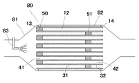
本発明の排気ガス浄化装置の模式断面図を図5に示す。本発明の排気ガス浄化装置80は、多孔質セラミックハニカム構造体の流路を目封止することによりハニカム構造体の隔壁に形成された細孔に排気ガスを通過させる構造のセラミックハニカムフィルタ12と、その上流側に配置された排気ガスの温度を上昇させるための燃料添加装置83とから構成され、前記セラミックハニカムフィルタは、少なくとも排気ガス流出側目封止部51の一部がセラミックハニカムフィルタの排気ガス流出側端面14より離れて配置され、前記排気ガス流出側目封止部より排気ガス流入側の隔壁31の少なくとも一部に触媒物質が担持されると共に、前記排気ガス流出側目封止部より排気ガス流出側の隔壁32の少なくとも一部に吸着剤及び/又は触媒物質が担持されていることを特徴とする理由を以下に説明する。ディーゼルエンジンから排出された排気ガス中の粒子状物質は、多孔質セラミックハニカム構造体の流路を目封止することによりハニカム構造体の隔壁に形成された細孔に排気ガスを通過させる構造のセラミックハニカムフィルタであって、少なくとも排気ガス流出側目封止部51の一部が排気ガス流出側端面14より離れて配置され、前記排気ガス流出側目封止部51より排気ガス流入側の隔壁31の少なくとも一部に触媒物質が担持され、前記排気ガス流出側目封止部51より排気ガス流出側の隔壁32の少なくとも一部に吸着剤及び/又は触媒物質が担持されているセラミックハニカムフィルタにおいて、前記排気ガス流出側目封止部より排気ガス流入側隔壁31の表面或いは隔壁中の細孔中に捕集され、この隔壁31の少なくとも一部に担持された触媒物質の作用により有効に燃焼除去されると共に、隔壁31を通過した後の排気ガスは排気ガス流出側目封止部より排気ガス流出側の流路42を通過して排出される際に、この排気ガス中に僅かに残存している微細な粒子状物質は、隔壁32の少なくとも一部に担持されている吸着剤及び/又は触媒物質により捕集及び/又は浄化される。これによって、排気ガス中の粒子状物質の排出量を低減することができる。
A schematic cross-sectional view of the exhaust gas purifying apparatus of the present invention is shown in FIG. The exhaust
上記のような粒子状物質の排出量を低減させる作用効果は、従来技術の図1に示すセラミックハニカムフィルタの排気ガス流出側に、吸着剤或いは触媒物質等を担持させたストレートフロータイプのセラミックハニカム構造体を直列に配置させた構成としても具現不可能ではないが、先に記したように、本発明の排気ガス浄化装置に用いられるセラミックハニカムフィルタの場合、図2に示すように多孔質隔壁31を通過した排気ガスは、排気ガス流出側に開口した流路42から43へと直接流入することから、前記圧力損失は発生せず、排気ガス浄化装置の圧力損失を低く押さえることができるという効果を有していると共に、流出側目封止部51の流出側の隔壁32と流路44を排気ガス中の微粒子状物質の捕集・浄化に有効に利用できる。
The effect of reducing the discharge amount of the particulate matter as described above is the straight flow type ceramic honeycomb in which an adsorbent or a catalytic substance is supported on the exhaust gas outflow side of the ceramic honeycomb filter shown in FIG. Although it cannot be realized as a structure in which the structures are arranged in series, as described above, in the case of the ceramic honeycomb filter used in the exhaust gas purification apparatus of the present invention, as shown in FIG. The exhaust gas that has passed through 31 directly flows into the
ここで、セラミックハニカムフィルタの上流側に排気ガスの温度を上昇させるための燃料添加装置83が配置されている理由を以下に説明する。近年のディーゼルエンジンは燃費向上が進み、排気ガス温度は低下する傾向にあり、200℃以下の排気ガス温度頻度が高くなるため、セラミックハニカムフィルタの排気ガス流出側目封止部51より排気ガス流入側の隔壁31において、排気ガス温度が低下して触媒物質の活性度が低下し、粒子状物質の燃焼が十分行われない時には、粒子状物質がセラミックハニカムフィルタ上に堆積して、セラミックハニカムフィルタの圧力損失が大きくなる場合がある。このような場合には、セラミックハニカムフィルタの上流側に配置された燃料添加装置83から排気ガス中に燃料を添加すると、排気ガス流出側目封止部51より排気ガス流出側の隔壁31の少なくとも一部に担持された触媒物質、例えば白金族金属を含む触媒物質により、燃料の燃焼反応が促進され、排気ガス温度が上昇するのと共に、セラミックハニカムフィルタの温度が上昇し、堆積していた粒子状物質が燃焼除去されるからである。同時に、前記排気ガス流出側目封止部より排気ガス流出側の隔壁32の少なくとも一部に担持されていた、吸着剤に吸着されていた、主として微細な粒子状物質が、吸着材から脱離し、高温の排気ガスによって、燃焼除去されるからである。或いは、前記排気ガス流出側目封止部より排気ガス流出側の隔壁32の少なくとも一部に担持されていた、触媒物質により排気ガス中に僅かに残留していた粒子状物質が、燃焼除去されるからである。
Here, the reason why the
本発明の排気ガス浄化装置において、前記セラミックハニカムフィルタ12と燃料添加装置83の間に、白金族金属を含む触媒物質が担持されたセラミックハニカム構造体が配置されていると、燃料添加装置から添加された燃料が、白金族金属を含む触媒物質が担持されたセラミックハニカム構造体において、燃料の酸化燃焼反応が促進され、排気ガスが高温化した状態で、セラミックハニカムフィルタに流入することから、セラミックハニカムフィルタに堆積していた粒子状物質の燃焼が効率良く行えるため、好ましい。
In the exhaust gas purifying apparatus of the present invention, when a ceramic honeycomb structure carrying a catalyst material containing a platinum group metal is disposed between the
なお、本発明のセラミックハニカムフィルタに好適な、セラミックハニカム構造体の隔壁の結晶相主成分がコーディエライトであり、気孔率が50〜80%であって、前記セラミックハニカム構造体の隔壁がFeを含むとともに、スピネルを含み、該スピネルの含有量はX線回折強度比にして4%以下であり、該スピネルの粒径は0.01〜5μmのものが含まれるセラミックハニカム構造体を得るには、コーディエライト化原料粉末の選定と配合比、および焼成時の昇温速度、最高温度での保持時間、冷却速度を適宜変えることにより可能となる。 In addition, the crystal phase main component of the partition of the ceramic honeycomb structure suitable for the ceramic honeycomb filter of the present invention is cordierite, the porosity is 50 to 80%, and the partition of the ceramic honeycomb structure is Fe In order to obtain a ceramic honeycomb structure including spinel, the content of the spinel is 4% or less in terms of the X-ray diffraction intensity ratio, and the particle size of the spinel is 0.01 to 5 μm. This can be achieved by appropriately changing the selection and blending ratio of the cordierite forming raw material powder, the heating rate during firing, the holding time at the maximum temperature, and the cooling rate.
以下に上記セラミックハニカム構造体を製造する方法の一例を示す。コーディエライト化原料粉末には、カオリン、タルクに加えて、更にシリカ、アルミナ、水酸化アルミニウム等を使用する。ここで、カオリン中のFe2O3含有量は0.2〜0.8質量%、タルク中のFe2O3濃度は0.5〜1.8質量%、シリカ中のFe2O3濃度は0.001〜0.1質量%とする。そして、カオリンの粒度分布は、粒径20μm以上の粉末を0〜10質量%、粒径10μm以上の粉末を5〜25質量%、粒径5μm以上の粉末を15〜50質量%、粒径2μm以上の粉末を50〜90質量%で含有したものを使用し、タルクの粒度分布は粒径45μm以上の粉末を3〜20質量%、粒径20μm以上の粉末を20〜40質量%、粒径10μm以上の粉末を50〜70質量%、粒径5μm以上の粉末を70〜90質量%、粒径2μm以上の粉末を80〜95質量%で含有したものを使用するのが好ましい。また、シリカの粒度分布は、粒径75〜250μmの粉末を1〜10質量%、粒径45μm以上の粉末を3〜25質量%、粒径20μm以上の粉末を31〜52質量%、粒径10μm以上の粉末を49〜70質量%、粒径5μm以上の粉末を65〜90質量%、粒径2μm以上の粉末を80〜99.5質量%で含有したものを使用するのが好ましい。このような、粒度分布とFe2O3を含有するカオリン、タルク及びシリカを使用することにより、コーディエライト合成過程で、主結晶としてコーディエライトが析出するとともに、微細なスピネルが析出し易くなり、さらにFeがスピネル中に高濃度で存在しやすくなる。ここで、コーディエライト化原料粉末にはFe2O3以外にもCaO、Na2O、K2O、TiO2、PbO、P2O5等の不可避的に混入する成分が混入存在しても良い。 An example of a method for manufacturing the ceramic honeycomb structure will be described below. In addition to kaolin and talc, silica, alumina, aluminum hydroxide and the like are used as the cordierite forming raw material powder. Here, Fe 2 O 3 content in the kaolin 0.2-0.8 wt%, Fe 2 O 3 concentration is 0.5-1.8 wt% in talc, Fe 2 O 3 concentration in the silica Is 0.001 to 0.1 mass%. The particle size distribution of kaolin is 0 to 10% by mass for powders with a particle size of 20 μm or more, 5 to 25% by mass for powders with a particle size of 10 μm or more, 15 to 50% by mass for powders with a particle size of 5 μm or more, and 2 μm particle size. A powder containing 50 to 90% by mass of the above powder is used, and the particle size distribution of talc is 3 to 20% by mass of powder having a particle size of 45 μm or more, 20 to 40% by mass of powder having a particle size of 20 μm or more, and particle size. It is preferable to use a powder containing 50 to 70% by mass of powder having a particle size of 10 μm or more, 70 to 90% by mass of powder having a particle size of 5 μm or more, and 80 to 95% by mass of powder having a particle size of 2 μm or more. The particle size distribution of the silica is 1 to 10% by mass of powder having a particle size of 75 to 250 μm, 3 to 25% by mass of powder having a particle size of 45 μm or more, 31 to 52% by mass of powder having a particle size of 20 μm or more, and particle size. It is preferable to use a powder containing 49 to 70% by mass of powder having a particle size of 10 μm or more, 65 to 90% by mass of powder having a particle size of 5 μm or more, and 80 to 99.5% by mass of powder having a particle size of 2 μm or more. By using kaolin, talc and silica containing such particle size distribution and Fe 2 O 3 , cordierite precipitates as a main crystal and fine spinel easily precipitates during the cordierite synthesis process. In addition, Fe is likely to be present at a high concentration in the spinel. Here, in addition to Fe 2 O 3 , inevitable components such as CaO, Na 2 O, K 2 O, TiO 2 , PbO, and P 2 O 5 are mixed in the cordierite forming raw material powder. Also good.
コーディエライト化原料粉末の配合組成は、SiO2、Al2O3、MgOの合計に対してSiO2:48〜50質量%、Al2O3:35〜37質量%、MgO:13〜15質量%となるように調整することが望ましい。前記範囲を外れると、スピネルの析出量が4質量%を越えたり、所望のスピネルが析出しないこともあり好ましくない。 The composition of the cordierite-forming raw material powder, SiO 2, Al 2 O 3 , SiO relative to the sum of MgO 2: 48 to 50 wt%, Al 2 O 3: 35~37 wt%, MgO: 13 to 15 It is desirable to adjust so that it may become mass%. Outside the above range, the amount of spinel deposited exceeds 4% by mass, and the desired spinel does not precipitate.
また高気孔率を得るための造孔剤は、公知のものが使用可能であり、焼成過程で燃焼して消失する有機発泡材、ミクロバルーン、天然黒鉛、人造黒鉛、カーボン、小麦粉、でん粉、木炭、パルプ粉や、ポリエチレン、ポリスチレン、ポリプロピレン、ナイロン、ポリエステル、アクリル、フェノール、エポキシ、エチレン−酢酸ビニル共重合体、スチレン−ブタジエンブロック重合体、スチレン−イソプレンブロック重合体、ポリメチルメタクリレート、メチルメタクリレートアクリロニトリル共重合体、ウレタン及びワックス等の樹脂等が使用可能であり特に限定されない。これらの従来使用されてきた造孔剤に加えて、分解温度の異なる造孔剤を複数添加することで、造孔剤が狭い温度範囲で瞬時に熱分解或いは燃焼することにより発生する割れを防ぐと共に、造孔剤により気孔が形成され、高気孔率であり、結晶相主成分がコーディエライトであるセラミックハニカム構造体を得ることもできる。 As the pore-forming agent for obtaining a high porosity, known ones can be used, and organic foams, microballoons, natural graphite, artificial graphite, carbon, wheat flour, starch, charcoal that disappears by burning in the firing process. , Pulp powder, polyethylene, polystyrene, polypropylene, nylon, polyester, acrylic, phenol, epoxy, ethylene-vinyl acetate copolymer, styrene-butadiene block polymer, styrene-isoprene block polymer, polymethyl methacrylate, methyl methacrylate acrylonitrile Copolymers, resins such as urethane and wax can be used, and are not particularly limited. In addition to these conventionally used pore forming agents, the addition of a plurality of pore forming agents having different decomposition temperatures prevents cracking caused by instantaneous thermal decomposition or combustion of the pore forming agent in a narrow temperature range. At the same time, it is possible to obtain a ceramic honeycomb structure in which pores are formed by the pore-forming agent, the porosity is high, and the main component of the crystal phase is cordierite.
造孔剤の添加量はその種類により異なるため所望の気孔率となるよう適宜使用する必要がある。例えば有機発泡材であればコーディエライト化原料粉末100質量部に対して、1〜15質量部とすることが好ましく、小麦粉であれば40〜50質量部が好ましい。これにより高気孔率であり、結晶相主成分がコーディエライトであるセラミックハニカム構造体を得ることが可能になる。 Since the addition amount of the pore-forming agent varies depending on the type, it is necessary to use it appropriately so as to obtain a desired porosity. For example, if it is an organic foam material, it is preferable to set it as 1-15 mass parts with respect to 100 mass parts of cordierite-forming raw material powder, and 40-50 mass parts is preferable in the case of wheat flour. This makes it possible to obtain a ceramic honeycomb structure having a high porosity and having a crystal phase main component of cordierite.
焼成条件は、最高温度を1350〜1450℃とし、保持時間は5時間以上、好ましくは10時間以上とすることにより、コーディエライト化が促進されるとともに、微細なスピネルを含み、結晶相主成分がコーディエライトであるセラミックハニカム構造体が得られる。そして、昇温過程では、セラミックハニカム構造体の熱収縮する温度域の昇温速度を30℃/h未満とし、熱収縮終了後の温度域の昇温速度を80℃/h未満とすることが好ましい。ここで、熱収縮する温度域とは約1000℃〜1200℃のことを言う。上記のように調整したコーディエライト化原料粉末と、昇温過程での昇温速度を調整することにより、主結晶としてコーディエライトが析出するとともに、微細なスピネルが析出し易くなり、さらにFeがスピネル中に高濃度で存在しやすくなる。尚、冷却過程で冷却速度を30℃/h以上に早くすることによってもスピネルの粒径をより微細にする効果がある。 The firing condition is that the maximum temperature is 1350 to 1450 ° C., and the holding time is 5 hours or more, preferably 10 hours or more, so that cordierite formation is promoted and fine spinel is included, and the main component of the crystal phase Is a cordierite ceramic honeycomb structure. In the temperature raising process, the temperature rising rate in the temperature region where the ceramic honeycomb structure undergoes heat shrinkage may be less than 30 ° C./h, and the temperature rising rate in the temperature region after the heat shrinking may be less than 80 ° C./h. preferable. Here, the temperature range where heat shrinks refers to about 1000 ° C to 1200 ° C. By adjusting the cordierite-forming raw material powder adjusted as described above and the heating rate during the heating process, cordierite precipitates as the main crystal, and fine spinel easily precipitates. Tends to be present in spinel at high concentrations. In addition, it is effective in making the particle size of a spinel finer also by making a cooling rate to 30 degrees C / h or more in a cooling process.
本発明のセラミックハニカムフィルタによれば、少なくとも排気ガス流出側目封止部の一部が排気ガス流出側端面より離れて配置されていることから、排気ガス流出側の目封止部より上流側の隔壁で粒子状物質が捕集される共に、当該隔壁で除去できなかった、微細な粒子状物質が排気ガス流出側目封止部より排気ガス流出側の隔壁を用いることによって、捕集或いは浄化されるため、ハニカム構造体の両端部で目封止された従来技術のセラミックハニカムフィルタに比べて、圧力損失を大きく上昇させることなく、排気ガス中に含まれる粒子状物質を高効率で浄化することができ、粒子状物質の排出量を低減することができる。 According to the ceramic honeycomb filter of the present invention, at least a part of the exhaust gas outflow side plugging portion is disposed away from the end surface of the exhaust gas outflow side, so that the upstream side from the plugging portion on the exhaust gas outflow side Particulate matter is collected by the partition wall, and fine particulate matter that could not be removed by the partition wall is collected or separated by using the partition wall on the exhaust gas outflow side from the exhaust gas outflow side plugging portion. Because it is purified, the particulate matter contained in the exhaust gas is purified with high efficiency without significantly increasing the pressure loss compared to the conventional ceramic honeycomb filter plugged at both ends of the honeycomb structure. The amount of particulate matter discharged can be reduced.
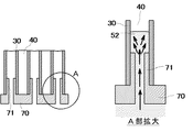
以下、本発明のセラミックハニカムフィルタの製造方法の一例を図6を用いて説明する。セラミックハニカム構造体の排気ガス流出側端面に市松模様に樹脂製スラリー導入通路71を設けた樹脂製のマスク70を装着し、図6のA部拡大図の矢印で示すようにスラリー導入通路71を通してスラリー状の目封止材52を導入、ハニカム構造体の流路の一部に充填する。その後、スラリー状の目封止材52中に含まれる水分はハニカム構造体の隔壁に吸水され目封止材が隔壁に着肉して行き保形性が得られるようになると、固化していないスラリーを排出し、樹脂製マスクを除去後、固化した目封止材の乾燥を行う。このとき樹脂製スラリー導入通路71内に存在するスラリー状の目封止材は隔壁からの吸水が無いことから固化しないため、スラリ−導入通路の長さを調整することにより、排気ガス流出側目封止部のハニカム構造体流出側端面からの形成位置を決定することができる。一方、排気ガス流入側の端面は、公知の技術により端部に目封止部を形成し、その後、目封止材の焼成を行い、隔壁と目封止材を一体化せしめる。
Hereinafter, an example of the method for manufacturing the ceramic honeycomb filter of the present invention will be described with reference to FIG. A
なお、目封止部を隔壁端面から離れて形成するその他の方法としては、注射針状の管をハニカム構造体の端部から流路の所定位置まで挿入し、この管を通して所定位置に所定量のペースト状の目封止材を導入後、乾燥、焼成させる方法や、セラミックチップをハニカム構造体の内部に埋め込み、焼成させる方法等を採用し、隔壁と目封止材を一体化することができる。更には、両端部が目封止されたセラミックハニカム構造体、及び一方の端部が目封止されたセラミックハニカム構造体とを、目封止部が形成されている端面同士を突き合わせ、目封止部を一体化させることにより製造することも可能である。具体的には未焼成の目封止部同士を突き合わせ焼成一体化、或いは焼成済み目封止部の場合は突き合わせ面に無機系接着剤を介在させ一体化することができる。また、両端が目封止されたセラミックハニカム構造体と、目封止部が形成されていないセラミックハニカム構造体を直列に配置し、端面同士を接合一体化せしめることにより製造することも可能である。具体的には、接合面の一部に無機系の接着剤を介在させる方法等を採用することができる。 As another method for forming the plugged portion away from the end face of the partition wall, an injection needle tube is inserted from the end of the honeycomb structure to a predetermined position of the flow path, and a predetermined amount is passed through the tube to a predetermined position. After the paste-like plugging material is introduced, a method of drying and firing, a method of embedding and firing ceramic chips in the honeycomb structure, and the like can be adopted to integrate the partition walls and the plugging material. it can. Further, the ceramic honeycomb structure having both ends plugged and the ceramic honeycomb structure having one end plugged are brought into contact with each other at the end surfaces where the plugged portions are formed, and sealed. It is also possible to manufacture by integrating the stopper. Specifically, unfired plugged portions can be butt-fired and integrated, or in the case of a baked plugged portion, an inorganic adhesive can be interposed on the butt surface for integration. Further, it is also possible to manufacture a ceramic honeycomb structure having both ends plugged and a ceramic honeycomb structure having no plugged portions arranged in series and joining and integrating the end faces. . Specifically, a method of interposing an inorganic adhesive on a part of the joining surface can be employed.
また、上記のように両端部で目封止が施されたセラミックハニカムフィルタと一方の端部が目封止されたハニカム構造体、或いは目封止の施されていないハニカム構造体とを一体化させる際に、両者の外周部に一体的に外周壁を形成する方法を用いると更に強固に一体化がなされる。或いは、セラミックハニカム構造体の外周部を加工により除去して、外周部に軸方向に延びる凹溝を有する形態とした後に、この凹溝にセラミックコーティング材を埋め込んで外周壁を一体的に形成しても良い。なお、この外周部の加工は、ハニカム構造の成形体の段階で行った後、焼成しても良いし、焼成後に行っても良い。また、このセラミックコーティング材は、ハニカム構造体と一体化させることから、ハニカム構造体と同一のセラミック粒子と、コロイド状酸化物等の無期バインダーで形成すると、コーティング材とハニカム構造体間における熱膨張等の材料特性の違いによる剥離等の問題を極力小さくできることから好ましい。 In addition, the ceramic honeycomb filter plugged at both ends as described above and the honeycomb structure plugged at one end, or the honeycomb structure not plugged at one end are integrated. In this case, if a method of integrally forming the outer peripheral wall at the outer peripheral portion of both is used, the integration is further strengthened. Alternatively, after the outer peripheral portion of the ceramic honeycomb structure is removed by processing to form a groove having an axially extending groove in the outer peripheral portion, the outer peripheral wall is integrally formed by embedding the ceramic coating material in the concave groove. May be. Note that the processing of the outer peripheral portion may be performed after being performed at the stage of the formed body of the honeycomb structure, and may be performed after the firing. Since this ceramic coating material is integrated with the honeycomb structure, thermal expansion between the coating material and the honeycomb structure can be achieved by forming the same ceramic particles as the honeycomb structure and a permanent binder such as colloidal oxide. It is preferable because problems such as peeling due to differences in material characteristics such as can be minimized.
更に、前記軸方向に延びる凹溝と外周壁を構成する部材の間の少なくとも一部に空隙を有しているとセラミックハニカムフィルタの耐熱衝撃性が大幅に向上するため好ましい。即ち、本発明のセラミックハニカムフィルタが例えば粒子状物質の燃焼により急熱された場合に、熱衝撃により外周壁部に発生する応力をこの空隙が開放するため、外周壁に発生したクラックの隔壁への進展を防ぎ、隔壁が脱落して、入口側と出口側の流路が連通し、粒子状物質の捕集率が低下するといった、排気ガス浄化装置の浄化性能に係わる、致命的な問題に発展することを防ぐことが出来るからである。また、空隙を設けることにより、外周壁部と凹溝を構成する隔壁の間の接着面積が小さくなることから、両者界面の熱膨張係数差により生じる残留応力が低減できるため、熱衝撃によるクラックが発生しにくいからである。ここで、前記外周壁を構成する部材と凹溝の間に形成された空隙を有する凹溝の個数割合が全凹溝のうちの5%以上であるとより好ましい。また、外周壁の少なくとも一部に外表面に開口した空隙を有していると、同様に耐熱衝撃性が向上することから好ましい。上記、セラミックハニカム構造体の外周部を加工により除去して、外周部に軸方向に延びる凹溝を有する形態とした後に、この凹溝にセラミックコーティング材を埋め込んで外周壁を一体的に形成し、凹溝と外周壁を構成する部材の間の少なくとも一部に空隙を有している場合の効果について、両端部で目封止が施されたセラミックハニカムフィルタと一方の端部が目封止されたハニカム構造体、或いは目封止の施されていないハニカム構造体とを一体化させる例を用いて説明したが、ハニカム構造体の内部に図6に示す方法、或いは、注射針状の管をハニカム構造体の端部から流路の所定位置まで挿入し、この管を通して所定位置に所定量のペースト状の目封止材を導入後、乾燥、焼成させる方法や、セラミックチップをハニカム構造体の内部に埋め込み、焼成させる方法等で得られたセラミックハニカム構造体の場合でも、耐熱衝撃性が向上するという同様の効果が得られることは言うまでもない。 Furthermore, it is preferable to have an air gap in at least a part between the axially extending groove and the member constituting the outer peripheral wall, since the thermal shock resistance of the ceramic honeycomb filter is greatly improved. That is, when the ceramic honeycomb filter of the present invention is rapidly heated by, for example, combustion of particulate matter, the stress that is generated in the outer peripheral wall due to thermal shock is released from the void, so that the cracks generated in the outer peripheral wall are transferred to the partition walls. This is a fatal problem related to the purification performance of the exhaust gas purification device, such as the separation of the partition wall, the communication between the inlet and outlet channels, and the reduction of the particulate matter collection rate. This is because it can be prevented from developing. In addition, since the bonding area between the outer peripheral wall portion and the partition walls forming the concave groove is reduced by providing the gap, the residual stress caused by the difference in thermal expansion coefficient between the two interfaces can be reduced, so that cracks due to thermal shock are generated. This is because it hardly occurs. Here, it is more preferable that the ratio of the number of concave grooves having gaps formed between the members constituting the outer peripheral wall and the concave grooves is 5% or more of all the concave grooves. Moreover, it is preferable that at least a part of the outer peripheral wall has a void opened on the outer surface, since the thermal shock resistance is improved similarly. After removing the outer peripheral portion of the ceramic honeycomb structure by machining to have a groove having an axially extending groove in the outer peripheral portion, the outer peripheral wall is integrally formed by embedding the ceramic coating material in the groove. The ceramic honeycomb filter with plugged at both ends and one end plugged with respect to the effect when there is a gap in at least a part between the groove and the member constituting the outer peripheral wall The honeycomb structure or the honeycomb structure that has not been plugged has been described as an example. However, the method shown in FIG. Is inserted from the end of the honeycomb structure to a predetermined position of the flow path, a predetermined amount of paste-like plugging material is introduced into the predetermined position through this tube, and then dried and fired. of Embedding the section, even when the ceramic honeycomb structure obtained by the method in which firing, it is needless to say that the same effect of improving the thermal shock resistance is obtained.
その後、触媒物質からなるスラリー及び吸着剤からなるスラリーに浸漬後、焼成して隔壁に触媒物質及び吸着剤を担持させるが、排気ガス流出側目封止部より排気ガス流入側の隔壁31には、触媒物質からなるスラリーをセラミックハニカムフィルタの排気ガス流入側端面から浸漬し、排気ガス流出側目封止部より排気ガス流出側の隔壁32には、吸着剤からなるスラリーをセラミックハニカムフィルタの排気ガス流出側端面から浸漬して形成する。
Then, after being immersed in a slurry made of a catalyst material and a slurry made of an adsorbent, the catalyst material and the adsorbent are supported on the partition walls by firing, but the
以下、発明の実施の形態を詳細に説明する。
(実施例1〜3)
カオリン、タルク、シリカ、水酸化アルミ、アルミナなどの粉末を調整して、質量比で、SiO2 :47〜53%、Al2O3:32〜38%、MgO:12〜16%及びCaO、Na2O 、K2O、TiO2、Fe2O3、PbO、P2O5などの不可避的に混入する成分を全体で2.5%以下を含むようなコーディエライト生成原料粉末に、成形助剤と造孔剤を添加し、規定量の水を注入して更に十分な混合を行い、ハニカム構造に押出成形可能な坏土を調整した。そして、公知の押出成形用金型を用い押出成形し、外周壁と、この外周壁の内周側で隔壁により囲まれた断面が四角形状の流路を有するハニカム構造の成形体を作製し、乾燥後焼成を行って、隔壁のピッチ1.5mmで、隔壁厚さ0.3mmの隔壁構造を有し、隔壁の気孔率が65%であり、直径267mm、全長304mm、外周壁厚0.5mmのコーディエライトを結晶相主成分とするセラミックハニカム構造体を作製した。
Hereinafter, embodiments of the present invention will be described in detail.
(Examples 1-3)
Kaolin, talc, silica, aluminum hydroxide, to adjust the powder, such as alumina, in a mass ratio, SiO 2: 47~53%, Al 2 O 3: 32~38%, MgO: 12~16% , and CaO, In the cordierite-producing raw material powder containing 2.5% or less in total of components inevitably mixed such as Na 2 O, K 2 O, TiO 2, Fe 2 O 3 , PbO, P 2 O 5 , A forming aid and a pore-forming agent were added, a specified amount of water was injected, and further sufficient mixing was performed to prepare a clay that can be extruded into a honeycomb structure. Then, extrusion molding using a known extrusion mold, to produce a honeycomb structure molded body having a square-shaped passage surrounded by a partition wall on the outer peripheral wall and the inner peripheral side of the outer peripheral wall, After drying, firing was performed to have a partition wall structure with a partition wall pitch of 1.5 mm and a partition wall thickness of 0.3 mm, a partition wall porosity of 65%, a diameter of 267 mm, a total length of 304 mm, and an outer peripheral wall thickness of 0.5 mm. A ceramic honeycomb structure having cordierite as a main component of crystal phase was prepared.
このセラミックハニカム構造体に対して、排気ガス流出側目封止部の流出側端面51tがハニカム構造体端面から10mm、50mm、80mmと成るように、外径0.5mm、内径0.3mmのステンレス製のノズルを流路端部から挿入して、別に準備したコーディエライト製のペーストをノズルから注入して長さ約10mmの目封止部を形成し、その後排気ガス流入側目封止部を形成して、焼成一体化した図2に示すようなセラミックハニカムフィルタを作製した。
For this ceramic honeycomb structure, stainless steel having an outer diameter of 0.5 mm and an inner diameter of 0.3 mm so that the outflow
前記のセラミックハニカムフィルタに対して、排気ガス流出側目封止部より排気ガス流入側の隔壁にはPt、酸化セリウム、及び活性アルミナからなる触媒物質を担持させた。担持量はPt量で2g/L(ハニカムフィルタ容積1Lに対して2g担持の意味)とした。一方、排気ガス流出側目封止部より排気ガス流出側の隔壁表面にはβゼオライトからなる吸着剤層を形成し、実施例1〜3のセラミックハニカムフィルタとした。 In the ceramic honeycomb filter, a catalyst material composed of Pt, cerium oxide, and activated alumina was supported on the partition wall on the exhaust gas inflow side from the exhaust gas outflow side plugging portion. The supported amount was 2 g / L in terms of Pt amount (meaning 2 g supported per 1 L of honeycomb filter volume). On the other hand, an adsorbent layer made of β zeolite was formed on the surface of the partition wall on the exhaust gas outflow side from the exhaust gas outflow side plugging portion, whereby ceramic honeycomb filters of Examples 1 to 3 were obtained.
(比較例1)
実施例1〜3と同様の方法により、隔壁のピッチ1.5mmで、隔壁厚さ0.3mmの隔壁構造を有し、隔壁の気孔率が65%であり、直径267mm、全長304mmのハニカム構造体を作製した。次に、このハニカム構造体の両端面にマスキングフィルムを貼りつけた後、両端面の流路が交互に開口するよう市松模様に穿孔し、続いて、スラリー状の目封止材を端面より導入して目封止部を形成後、目封止材の焼成を行って、従来技術の両端部に交互に目封止部を有する図1に示すセラミックハニカムフィルタを作製した。そして、このセラミックハニカムフィルタに対して、実施例1〜3と同様に、Pt、酸化セリウム、及び活性アルミナからなる触媒物質を隔壁に担持させ(担持量はPt量で2g/L)、比較例1のセラミックハニカムフィルタとした。
(Comparative Example 1)
A honeycomb structure having a partition wall structure with a partition wall pitch of 1.5 mm, a partition wall thickness of 0.3 mm, a partition wall porosity of 65%, a diameter of 267 mm, and a total length of 304 mm by the same method as in Examples 1 to 3. The body was made. Next, after pasting a masking film on both end faces of this honeycomb structure, perforated in a checkered pattern so that the flow paths on both end faces are alternately opened, and subsequently introducing a slurry-like plugging material from the end faces Then, after forming the plugged portions, the plugging material was fired to produce the ceramic honeycomb filter shown in FIG. 1 having the plugged portions alternately at both ends of the prior art. And, in the same manner as in Examples 1 to 3, this ceramic honeycomb filter was loaded with a catalyst material comprising Pt, cerium oxide, and activated alumina on the partition walls (the amount supported was 2 g / L in terms of Pt amount), and a comparative example. 1 ceramic honeycomb filter.
(実施例4〜6)
比較例1と同様の方法により、隔壁のピッチ1.4mmで、隔壁厚さ0.32mmの隔壁構造を有し、隔壁の気孔率が62%であり、直径275mm、全長304mmである、セラミックハニカム構造体を作製した後、外周部の除去加工を行い、直径が265mmであり、最外周に位置する流路が、外部との間の隔壁を有しないことによって、外部に開口して軸方向に延びる凹溝を有し、コーディエライトを結晶相主成分とするセラミックハニカム構造体を作製した。その後、両端部に交互に目封止部を施し、所望の流路端部が目封止されたセラミックハニカムフィルタを作製した。一方、同様に、隔壁のピッチ1.4mmで、隔壁厚さ0.32mmの隔壁構造を有し、隔壁の気孔率が62%であり、直径275mm、全長10mm、50mm、80mmの目封止部を有しない3種類のセラミックハニカム構造体を得た後、外周部の除去加工を行い、直径が265mmであり、最外周に位置する流路が、外部との間の隔壁を有する3種類のセラミックハニカム構造体を得た。
(Examples 4 to 6)
A ceramic honeycomb having a partition wall structure having a partition wall pitch of 1.4 mm, a partition wall thickness of 0.32 mm, a partition wall porosity of 62%, a diameter of 275 mm, and a total length of 304 mm by the same method as in Comparative Example 1. After manufacturing the structure, the outer peripheral portion is removed, the diameter is 265 mm, and the flow path located on the outermost periphery does not have a partition wall between the outside, so that it opens to the outside in the axial direction. A ceramic honeycomb structure having a recessed groove extending and having cordierite as a main component of the crystal phase was produced. Thereafter, plugged portions were alternately applied to both end portions to produce a ceramic honeycomb filter in which desired flow path end portions were plugged. Similarly, a plug structure having a partition wall structure with a partition wall pitch of 1.4 mm and a partition wall thickness of 0.32 mm, a partition wall porosity of 62%, a diameter of 275 mm, a total length of 10 mm, 50 mm, and 80 mm. After obtaining three types of ceramic honeycomb structures having no outer periphery, the outer peripheral portion is removed, the diameter is 265 mm, and the flow channel located on the outermost periphery has partition walls between the outside and the three types of ceramic A honeycomb structure was obtained.
このセラミックハニカムフィルタと各々3種類のセラミックハニカム構造体の流路が連通するように両者の端面同士を突き合わせた後、両者の外部に開口して延びる流路にコーディエライト粒子とコロイダルシリカを含有するコーティング剤を塗布して、外周壁を形成し、両者を一体化することによって、直径が267mmで、全長314mm、354mm、384mmであり、排気ガス流出側目封止部がセラミックハニカムフィルタの排気ガス流出側端面より離れて配置された、セラミックハニカムフィルタを作製した。 The end surfaces of the ceramic honeycomb filter and the three types of ceramic honeycomb structures are in contact with each other so that the end faces of the ceramic honeycomb filter communicate with each other. By applying a coating agent to form an outer peripheral wall and integrating them, the diameter is 267 mm, the total length is 314 mm, 354 mm, and 384 mm, and the exhaust gas outlet side plugging portion is the exhaust of the ceramic honeycomb filter. A ceramic honeycomb filter disposed away from the end face on the gas outflow side was produced.
これらのセラミックハニカムフィルタに対して、実施例1〜3と同様に、排気ガス流出側目封止部より排気ガス流入側の隔壁にはPt、酸化セリウム、及び活性アルミナからなる触媒物質を担持させた。担持量はPt量で2g/L(ハニカムフィルタ容積1Lに対して2g担持の意味)とした。一方、排気ガス流出側目封止部より排気ガス流出側の隔壁表面にはゼオライト(ZSM−5)からなる吸着剤層を形成し、実施例4〜6のセラミックハニカムフィルタを得た。 For these ceramic honeycomb filters, as in Examples 1 to 3, the partition wall on the exhaust gas inflow side from the exhaust gas outflow side plugging portion is loaded with a catalyst material made of Pt, cerium oxide, and activated alumina. It was. The supported amount was 2 g / L in terms of Pt amount (meaning 2 g supported per 1 L of honeycomb filter volume). On the other hand, an adsorbent layer made of zeolite (ZSM-5) was formed on the surface of the partition wall on the exhaust gas outflow side from the exhaust gas outflow side plugging portion, and ceramic honeycomb filters of Examples 4 to 6 were obtained.
(実施例7)
実施例2と同様の方法で、隔壁のピッチ1.5mmで、隔壁厚さ0.3mmの隔壁構造を有し、隔壁の気孔率が65%であり、直径267mm、全長304mmのコーディエライトを結晶相主成分とするセラミックハニカム構造体に対して、排気ガス流出側目封止部の流出側端面51tがハニカム構造体端面から50mmと成るように、図6に示す方法で目封止部形成用スラリー排気ガス流出側目封止部51を形成し、その後排気ガス流入側目封止部を形成して、焼成一体化した図2に示すようなセラミックハニカムフィルタを作製した。
(Example 7)
A cordierite having a partition wall structure with a partition wall pitch of 1.5 mm, a partition wall thickness of 0.3 mm, a partition wall porosity of 65%, a diameter of 267 mm, and a total length of 304 mm was obtained in the same manner as in Example 2. The plugging portion is formed by the method shown in FIG. 6 so that the outflow
このセラミックハニカムフィルタに対して、実施例1〜3と同様に、排気ガス流出側目封止部より排気ガス流入側の隔壁にはPt、酸化セリウム、及び活性アルミナからなる触媒物質を担持させた。担持量はPt量で2g/L(ハニカムフィルタ容積1Lに対して2g担持の意味)とした。一方、排気ガス流出側目封止部より排気ガス流出側の隔壁表面にも、Pt、酸化セリウム、及び活性アルミナからなる触媒物質を担持させたが、担持量はPt量で5g/L(ハニカムフィルタ容積1Lに対して5g担持の意味)とした。 In the ceramic honeycomb filter, as in Examples 1 to 3, the partition wall on the exhaust gas inflow side from the exhaust gas outflow side plugging portion was loaded with a catalyst material made of Pt, cerium oxide, and activated alumina. . The supported amount was 2 g / L in terms of Pt amount (meaning 2 g supported per 1 L of honeycomb filter volume). On the other hand, a catalyst material composed of Pt, cerium oxide and activated alumina was supported on the partition wall surface on the exhaust gas outflow side from the exhaust gas outflow side plugging portion, but the supported amount was 5 g / L (honeycomb). The meaning is that 5 g is carried with respect to 1 L of the filter volume).
(比較例2)
比較例1と同様の方法により、隔壁のピッチ1.4mmで、隔壁厚さ0.32mmの隔壁構造を有し、隔壁の気孔率が62%であり、直径267mm、全長304mm、両端部に交互に目封止部を有する図1に示す従来技術のセラミックハニカムフィルタを作製した。一方、同様に、隔壁のピッチ1.4mmで、隔壁厚さ0.32mmの隔壁構造を有し、隔壁の気孔率が62%であり、直径267mm、50mm、の目封止部を有しないセラミックハニカム構造体を得た。
(Comparative Example 2)
In the same manner as in Comparative Example 1, the partition wall structure has a partition wall pitch of 1.4 mm and partition wall thickness of 0.32 mm, the partition wall porosity is 62%, the diameter is 267 mm, the total length is 304 mm, and alternately at both ends. A ceramic honeycomb filter according to the prior art shown in FIG. On the other hand, similarly, a ceramic having a partition wall structure with a partition wall pitch of 1.4 mm and a partition wall thickness of 0.32 mm, a partition wall porosity of 62%, and a diameter of 267 mm and 50 mm without plugging portions. A honeycomb structure was obtained.
このセラミックハニカムフィルタに対して、実施例1〜3と同様に、Pt、酸化セリウム、及び活性アルミナからなる触媒物質を担持させた。担持量はPt量で2g/L(ハニカムフィルタ容積1Lに対して2g担持の意味)とした。一方、セラミックハニカム構造体に対しては、ゼオライト(ZSM−5)からなる吸着剤層を形成した。 In the same manner as in Examples 1 to 3, the ceramic honeycomb filter was supported with a catalyst material composed of Pt, cerium oxide, and activated alumina. The supported amount was 2 g / L in terms of Pt amount (meaning 2 g supported per 1 L of honeycomb filter volume). On the other hand, an adsorbent layer made of zeolite (ZSM-5) was formed on the ceramic honeycomb structure.
上記のように作製した実施例1〜7及び比較例1のセラミックハニカムフィルタを圧力損失試験装置(図示せず)に設置し、空気流量7.5Nm3 /minの条件で空気を流入し、流入側端面と流出側端面の差圧を測定し、各セラミックハニカムフィルタの初期圧力損失を評価した。この初期圧力損失は、次に述べる比較例1のセラミックハニカムフィルタの初期圧力損失を1として、相対値で示した。更に、実施例1〜7及び比較例1のセラミックハニカムフィルタを、ディーゼルエンジンの排気管に配置し、市街地走行を模したパターン走行条件で粒子状物質排出量を測定した。この際、排気ガス温度が触媒物質の活性下限温度を下まわるような運転状態が続くような場合を発生させ、粒子状物質がフィルタ上に僅かに堆積するような条件を作り出した上で、この運転状態に応じて、フィルタの上流側に燃料を噴射して、粒子状物質を燃焼させた。そして、10,000km走行に相当する時点での、セラミックハニカムフィルタから排出された排気ガス中の粒子状物質排出量を測定し、次に述べる比較例1のセラミックハニカムフィルタの粒子状物質排出量を1として相対値で示した。 The ceramic honeycomb filters of Examples 1 to 7 and Comparative Example 1 manufactured as described above were installed in a pressure loss test apparatus (not shown), and air was introduced under the condition of an air flow rate of 7.5 Nm 3 / min. The differential pressure between the side end face and the outflow side end face was measured, and the initial pressure loss of each ceramic honeycomb filter was evaluated. The initial pressure loss is shown as a relative value, with the initial pressure loss of the ceramic honeycomb filter of Comparative Example 1 described below as 1. Furthermore, the ceramic honeycomb filters of Examples 1 to 7 and Comparative Example 1 were arranged in the exhaust pipe of a diesel engine, and the particulate matter discharge amount was measured under a pattern running condition simulating urban driving. In this case, an operation state in which the exhaust gas temperature falls below the lower limit temperature of activation of the catalyst material is generated, and after creating a condition that the particulate matter is slightly deposited on the filter, Depending on the operating conditions, fuel was injected upstream of the filter to burn particulate matter. Then, the particulate matter discharge amount in the exhaust gas discharged from the ceramic honeycomb filter at a time corresponding to 10,000 km travel is measured, and the particulate matter discharge amount of the ceramic honeycomb filter of Comparative Example 1 described below is measured. The relative value is shown as 1.
また、比較例2の場合は、上流側にセラミックハニカムフィルタを配置し、下流側にセラミックハニカム構造体を配置して、上記と同様に初期圧力損失及び粒子状物質排出量を測定した。 In the case of Comparative Example 2, a ceramic honeycomb filter was disposed on the upstream side and a ceramic honeycomb structure was disposed on the downstream side, and the initial pressure loss and particulate matter discharge were measured in the same manner as described above.
実施例1〜7及び比較例1及び2の初期圧力損失及び粒子上物質排出量の試験結果を表1に示す。 Table 1 shows the test results of the initial pressure loss and the on-particle discharge amount of Examples 1 to 7 and Comparative Examples 1 and 2.

本発明の実施例1〜6のセラミックハニカムフィルタは、比較例1のセラミックハニカムフィルタに比べて、排気ガス流出が目封止部より排気ガス流出側に吸着剤を担持した流路が形成されているため、圧力損失は大きくなる傾向は認められるが、粒子状物質の排出量を低減できるという大きな効果のあることがわかる。また、本発明の実施例7のセラミックハニカムフィルタは、比較例1のセラミックハニカムフィルタに比べて、排気ガス流出が目封止部より排気ガス流出側に触媒物質が担持された流路が形成されているため、圧力損失は大きくなる傾向は認められるが、粒子状物質の排出量を低減できるという大きな効果のあることがわかる。一方、比較例1のセラミックハニカムフィルタの排気ガス流出側に吸着剤を担持したセラミックハニカム構造体を配置した比較例2は、比較例1に比べ粒子状物質排出量は低減されたが、圧力損失は実施例1〜7に比べて大きくなった。 In the ceramic honeycomb filters of Examples 1 to 6 of the present invention, compared with the ceramic honeycomb filter of Comparative Example 1, the exhaust gas outflow is formed with a channel carrying an adsorbent on the exhaust gas outflow side from the plugging portion. Therefore, although the pressure loss tends to increase, it can be seen that there is a great effect that the discharge amount of the particulate matter can be reduced. Further, in the ceramic honeycomb filter of Example 7 of the present invention, compared with the ceramic honeycomb filter of Comparative Example 1, a flow path in which the exhaust gas outflow is supported on the exhaust gas outflow side from the plugging portion is formed. Therefore, it can be seen that the pressure loss tends to increase, but it has a great effect of reducing the discharge amount of the particulate matter. On the other hand, in Comparative Example 2 in which the ceramic honeycomb structure carrying the adsorbent was disposed on the exhaust gas outflow side of the ceramic honeycomb filter of Comparative Example 1, the amount of particulate matter discharged was reduced compared to Comparative Example 1, but the pressure loss Was larger than Examples 1-7.
(実施例8〜11)
表2〜3に示す平均粒径、粒度分布、Fe2O3含有量のカオリン、タルク、溶融シリカ、酸化アルミニウム、水酸化アルミニウム等のコーディエライト化原料を用い、表4に示す、(SiO2―Al2O3―MgO)の配合比が得られるよう秤量した。次いで、このコーディエライト化原料100質量部に対して、有機発泡剤を12質量部、メチルセルロース5質量%、ヒドロキシプロピルメチルセルロースを2質量%添加し、混合調整した。その後、このコーディエライト化原料100質量部に対して水を投入し、混合、混練を加え、可塑化可能な坏土を作製し、この坏土を押出成形機に投入して、ハニカム構造を有する成形体を得た。次いで得られた成形体をマイクロ波乾燥機で乾燥した後、熱風乾燥を行い、所定の寸法に両端面を切断した。その後、バッチ炉に投入し、1000〜1200℃間の昇温速度20℃/h、1200〜1350℃間の昇温速度50℃/h、1350〜1400℃間の昇温速度10℃/hとして、1400℃、10時間の条件で焼成を行い、直径267mm、長さ304mm、隔壁厚さ0.3mm、隔壁ピッチ1.58mmの寸法特性を有する実施例8〜11のコーディエライトを結晶相主成分とするセラミックハニカム構造体を各2ヶ得た。
(Examples 8 to 11)
Using cordierite-forming raw materials such as kaolin, talc, fused silica, aluminum oxide, and aluminum hydroxide having the average particle diameter, particle size distribution, and Fe 2 O 3 content shown in Tables 2 to 3, shown in Table 4 (SiO 2 2— Al 2 O 3 —MgO) was weighed to obtain a blending ratio. Next, 12 parts by mass of an organic foaming agent, 5% by mass of methylcellulose, and 2% by mass of hydroxypropylmethylcellulose were added to 100 parts by mass of this cordierite-forming raw material, and mixed and adjusted. Thereafter, water is added to 100 parts by mass of the cordierite forming raw material, and mixing and kneading are performed to produce a plasticizable clay, and this clay is put into an extrusion molding machine to obtain a honeycomb structure. A molded body having was obtained. Next, the obtained molded body was dried with a microwave dryer and then dried with hot air, and both end surfaces were cut into predetermined dimensions. Then, it puts into a batch furnace, The temperature increase rate between 1000-1200
得られたセラミックハニカム構造体の各2ヶのうちの1ヶから試験片を切り出し、Fe2O3量、スピネル/コーディエライトのX線回折強度比、コーディエライト結晶の配向度、TEM観察によるスピネル及びコーディエライト中のFe2O3量とスピネルの粒径、気孔率、熱膨張係数の測定を行った。 A test piece was cut out from one of the two ceramic honeycomb structures obtained, Fe 2 O 3 content, spinel / cordierite X-ray diffraction intensity ratio, cordierite crystal orientation, and TEM observation. The amount of Fe 2 O 3 in spinel and cordierite and the particle size, porosity, and thermal expansion coefficient of spinel were measured.
コーディエライトを結晶相主成分とするセラミックハニカム構造体中のFe2O3量は、ICP発光分析により求めた。 The amount of Fe 2 O 3 in the ceramic honeycomb structure containing cordierite as the main component of the crystal phase was determined by ICP emission analysis.
スピネル/コーディエライトのX線回折強度比は、コーディエライトを結晶相主成分とするセラミックハニカム構造体の任意部位より試験片を切り出した後、粉砕して粉末化し、目開き径1μmの篩を通過させて粒度調整した後、粉末X線回折装置(リガク社製RINT1500)を用いて一定条件(X線源CuKα1線、波長λ=1.540562Å、2θ範囲8°〜40°、走査速度2°/min.)においてX線回折強度測定を行い、得られたX線回折プロファイルをJCPDSファイル(Powder Diffraction File Published by JCPDS International Center for Diffraction Data)に登録されている無機化合物カードと照合し、コーディエライト結晶とスピネル結晶の同定を行った。スピネル/コーディエライトのX線回折強度比は、得られたX線回折プロファイルのIsp〔220〕(スピネル〔220〕面のX線回折強度)と、Ic〔102〕(コーディエライト〔102〕面のX線回折強度)を用い、Isp〔220〕/{Ic〔102〕}(%)として求めた。 The spinel / cordierite X-ray diffraction intensity ratio was determined by cutting a test piece from an arbitrary part of a ceramic honeycomb structure containing cordierite as a main component of the crystal phase, and then pulverizing it into a powder. After adjusting the particle size by passing through, a certain condition (X-ray source CuKα1 ray, wavelength λ = 1.540562Å, 2θ range 8 ° to 40 °, scanning speed 2) using a powder X-ray diffractometer (RINT 1500 manufactured by Rigaku Corporation) X-ray diffraction intensity measurement is performed at (° / min.), And the obtained X-ray diffraction profile is collated with an inorganic compound card registered in a JCPDS file (Powder Diffraction File Published by JCPDS International Diffraction Data). Elite crystal And spinel crystals were identified. The X-ray diffraction intensity ratio of spinel / cordierite is determined by Isp [220] (X-ray diffraction intensity of the spinel [220] plane) and Ic [102] (cordierite [102] of the obtained X-ray diffraction profile. (X-ray diffraction intensity of the surface) was obtained as Isp [220] / {Ic [102]} (%).
コーディエライト結晶の配向度は、コーディエライトを主結晶とするセラミックハニカム構造体の任意部位より試験片を切出し、隔壁面をX線照射面とし、上記と同様にX線回折強度測定を行った。コーディエライト結晶の配向度の評価は、得られたX線回折プロファイルのIc〔110〕(コーディエライト〔110〕面のX線回折強度)とIc〔002〕(コーディエライト〔002〕面のX線回折強度)を用いてI比=Ic〔110〕/{Ic〔110〕+Ic〔002〕}を求めた。 The degree of orientation of the cordierite crystal is determined by measuring the X-ray diffraction intensity in the same manner as described above by cutting a test piece from an arbitrary part of the ceramic honeycomb structure having cordierite as the main crystal and using the partition wall surface as the X-ray irradiation surface. It was. The degree of orientation of the cordierite crystal was evaluated based on Ic [110] (X-ray diffraction intensity of the cordierite [110] plane) and Ic [002] (cordierite [002] plane of the obtained X-ray diffraction profile. I ratio = Ic [110] / {Ic [110] + Ic [002]}.
スピネル及びコーディエライト中のFe2O3量とスピネルの粒径は、以下の手順で求めた。コーディエライトを主結晶とするセラミックハニカム構造体の任意部位より、集束イオンビーム加工装置(FIB、日立製作所製FB−2000A)を用いてマイクロサンプリング法により厚さ100nm程度に薄片化試件片を作成した後、得られた薄片化試験片に対して透過型電子顕微鏡(TEM、日立製作所製HF−2100型)を用いて、倍率10000倍程度でTEM像を観察し、コーディエライト及びスピネルの認められた視野のZコントラスト像の写真を撮影する。その後、微小箇所のEDX(エネルギ−分散型X線分析器)による組成分析を行って、スピネル及びコーディエライトの組成を求め、各々に含まれるFe2O3量を算出した。また、先に得られたZコントラスト像の写真から画像解析装置を用いて最大径aと前記最大径aに直交する径bとを測定し、二軸平均粒径r(r=(a+b)/2:最大径と最大径に直交する径の相加平均)をスピネルの粒径として求める。ここで、観察したスピネルのうち粒径0.01〜5μmであるスピネルの個数割合は、任意のスピネルをN個(20個以上)選択し、上記の様に粒径を計測し、粒径0.01〜5μmのスピネル観測数n個の全スピネル観測数N個に対する百分率n/N×100(%)として算出した。 The amount of Fe 2 O 3 in spinel and cordierite and the particle size of spinel were determined by the following procedure. From an arbitrary part of the ceramic honeycomb structure having cordierite as the main crystal, a sample piece to be thinned to a thickness of about 100 nm by a microsampling method using a focused ion beam processing apparatus (FIB, FB-2000A manufactured by Hitachi, Ltd.) After creation, the TEM image was observed at a magnification of about 10,000 times with a transmission electron microscope (TEM, HF-2100 manufactured by Hitachi, Ltd.) on the obtained thinned test piece, and cordierite and spinel Take a photo of the Z-contrast image of the recognized field of view. Thereafter, the micro-locations EDX - performing composition analysis by (energy dispersive X-ray analyzer), determine the composition of the spinel and cordierite, it was calculated the amount of Fe 2 O 3 included in each. In addition, the maximum diameter a and the diameter b orthogonal to the maximum diameter a are measured from the previously obtained Z contrast image using an image analyzer, and the biaxial average particle diameter r (r = (a + b) / 2: The arithmetic mean of the maximum diameter and the diameter orthogonal to the maximum diameter) is determined as the particle size of the spinel. Here, the number ratio of spinels having a particle size of 0.01 to 5 μm among the observed spinels is selected as N (20 or more) arbitrary spinels, and the particle size is measured as described above. It was calculated as a percentage n / N × 100 (%) with respect to the total number of spinel observations N of spinel observations n of 0.01 to 5 μm.
気孔率は、セラミックハニカム構造体より試験片を切出し、水銀ポロシメータ(米国MICROMERITICS社製AutoPore 4)を用いて、水銀圧入法より求めた。 The porosity was determined by mercury porosimetry using a mercury porosimeter (AutoPore 4 manufactured by MICROMERITICS, USA) by cutting a test piece from the ceramic honeycomb structure.
熱膨張係数は、コーディエライトを主結晶とするセラミックハニカム構造体より試験片を切出し、熱機械分析装置(TMA、リガク社製ThermoPlus、圧縮荷重方式/示差膨張方式)を用いて一定荷重20gのもと、温度範囲35〜800℃間を昇温速度10℃/min.で測定を行い、平均熱膨張係数として求めた。 The coefficient of thermal expansion was determined by cutting a test piece from a ceramic honeycomb structure having cordierite as the main crystal and using a thermomechanical analyzer (TMA, ThermoPlus, Rigaku Corporation, compression load method / differential expansion method) with a constant load of 20 g. Originally, the temperature increase rate is 10 ° C./min. And measured as an average coefficient of thermal expansion.
これら実施例8〜11のセラミックハニカム構造体試験片の試験結果を表5に示す。表5に示すように、実施例8〜10のセラミックハニカム構造体は、結晶相主成分がコーディエライトであり、FeをFe2O3換算で0.65〜0.77質量%含むとともに、スピネルを含み、該スピネルの含有量はX線回折強度比にして0.6〜3.7%であり、該スピネルの粒径は0.01〜5μmのものが含まれることから、また、(スピネル中のFe2O3濃度)/(コーディエライト中のFe2O3濃度)の値が1.1以上であることから、12×10−7/℃以下の低い熱膨張係数を示した。 Table 5 shows the test results of the ceramic honeycomb structure test pieces of Examples 8 to 11. As shown in Table 5, in the ceramic honeycomb structures of Examples 8 to 10, the main component of the crystal phase is cordierite, and Fe is contained in an amount of 0.65 to 0.77% by mass in terms of Fe 2 O 3 . Since spinel is included, the content of the spinel is 0.6 to 3.7% in terms of the X-ray diffraction intensity ratio, and the particle size of the spinel is 0.01 to 5 μm. since the value of Fe 2 O 3 concentration in the spinel) / (Fe 2 O 3 concentration in the cordierite) is 1.1 or more, it showed a low thermal expansion coefficient of 12 × 10 -7 / ℃ or less .
また、実施例11のセラミックハニカム構造体は、スピネルが存在しても、スピネル/コーディエライトのX線回折強度比が4%を越えていたため、熱膨張係数は13.8×10−7/℃であった。 Further, in the ceramic honeycomb structure of Example 11, even when spinel was present, the X-ray diffraction intensity ratio of spinel / cordierite exceeded 4%, so the thermal expansion coefficient was 13.8 × 10 −7 / ° C.
また、実施例8〜11のコーディエライトを結晶相主成分とするセラミックハニカム構造体の残り各1ケにつき、実施例2と同様の方法で、排気ガス流出側目封止部の流出側端面51tがハニカム構造体端面から50mmと成るように、外径0.5mm、内径0.3mmのステンレス製のノズルを流路既端部から挿入して、別に準備したコーディエライト製のペーストをノズルから注入して長さ約10mmの目封止部を形成し、その後排気ガス流入側目封止部を形成して、焼成一体化した図2に示すようなセラミックハニカムフィルタを作製した。 Further, for each remaining one of the ceramic honeycomb structures having cordierite as a main component of the crystal phase of Examples 8 to 11, the exhaust side end face of the exhaust gas outlet side plugging portion was obtained in the same manner as in Example 2. Insert a stainless steel nozzle with an outer diameter of 0.5 mm and an inner diameter of 0.3 mm from the end of the flow path so that 51t is 50 mm from the end face of the honeycomb structure, and use a cordierite paste prepared separately. Was injected to form a plugging portion having a length of about 10 mm, and then an exhaust gas inflow side plugging portion was formed to produce a fired integrated ceramic honeycomb filter as shown in FIG.
前記のセラミックハニカムフィルタに対して、排気ガス流出側目封止部より排気ガス流入側の隔壁にはPt、酸化セリウム、及び活性アルミナからなる触媒物質を担持させた。担持量はPt量で2g/L(ハニカムフィルタ容積1Lに対して2g担持の意味)とした。一方、排気ガス流出側目封止部より排気ガス流出側の隔壁表面にはβゼオライトからなる吸着剤層を形成し、実施例8〜11のセラミックハニカムフィルタとした。 In the ceramic honeycomb filter, a catalyst material composed of Pt, cerium oxide, and activated alumina was supported on the partition wall on the exhaust gas inflow side from the exhaust gas outflow side plugging portion. The supported amount was 2 g / L in terms of Pt amount (meaning 2 g supported per 1 L of honeycomb filter volume). On the other hand, an adsorbent layer made of β zeolite was formed on the surface of the partition wall on the exhaust gas outflow side from the exhaust gas outflow side plugging portion to obtain ceramic honeycomb filters of Examples 8 to 11.
上記のように作製した実施例8〜11のセラミックハニカムフィルタを実施例1〜7の場合と同様の方法で、初期圧力損失及び粒子状物質排出量を測定した。 The ceramic honeycomb filters of Examples 8 to 11 produced as described above were measured for initial pressure loss and particulate matter discharge in the same manner as in Examples 1 to 7.
これら実施例8〜11のセラミックハニカムフィルタの初期圧力損失及び粒子上物質排出量の試験結果を表6に示す。本発明の実施例8〜11のセラミックハニカムフィルタは、比較例1のセラミックハニカムフィルタに比べて、排気ガス流出が目封止部より排気ガス流出側に吸着剤を担持した流路が形成されているため、圧力損失は大きくなる傾向は認められるが、粒子状物質の排出量を低減できるという大きな効果のあることがわかる。 Table 6 shows the test results of the initial pressure loss and the on-particle substance discharge amount of the ceramic honeycomb filters of Examples 8 to 11. In the ceramic honeycomb filters of Examples 8 to 11 of the present invention, compared with the ceramic honeycomb filter of Comparative Example 1, the exhaust gas outflow is formed with a channel carrying an adsorbent on the exhaust gas outflow side from the plugging portion. Therefore, although the pressure loss tends to increase, it can be seen that there is a great effect that the discharge amount of the particulate matter can be reduced.
10:セラミックハニカム構造体
11:従来のセラミックハニカムフィルタ
12:本発明のセラミックハニカムフィルタ
13:排気ガス流入側端面
14:排気ガス流出側端面
15:燃料添加装置
20:外周壁
30:隔壁
31:流出側目封止部より排気ガス流入側の隔壁
32:流出側目封止部より排気ガス流出側の隔壁
33:流入側目封止部より排気ガス流入側の隔壁
40:流路
41:流入側端面で開口している流路
42:流出側端面で開口している流路
43:流出側端面で開口している流路
44:流出側目封止部より排気ガス流出側の流路
50:流入側目封止部
50t:流入側目封止部の流入側端面
51:流出側目封止部
51t:流出側目封止部の流出側端面
52:目封止部形成用スラリー
70:マスク
71:スラリー導入通路
80:本発明の排気ガス浄化装置
81:金属製容器
82:把持部材
83:燃料添加装置
91:流入する排気ガス
92:流出する排気ガス
10: Ceramic honeycomb structure 11: Conventional ceramic honeycomb filter 12:
Claims (9)
少なくとも排気ガス流出側目封止部の一部がセラミックハニカムフィルタの排気ガス流出側端面より離れて配置されていることを特徴とするセラミックハニカムフィルタ。 In a ceramic honeycomb filter having a structure in which exhaust gas is passed through pores formed in partition walls of a honeycomb structure by plugging a flow path of the porous ceramic honeycomb structure,
A ceramic honeycomb filter characterized in that at least a part of the exhaust gas outflow side plugging portion is disposed away from the exhaust gas outflow side end face of the ceramic honeycomb filter.
Priority Applications (1)
| Application Number | Priority Date | Filing Date | Title |
|---|---|---|---|
| JP2005036802A JP2005296936A (en) | 2004-02-12 | 2005-02-14 | Ceramic honeycomb filter and exhaust gas cleaning apparatus |
Applications Claiming Priority (3)
| Application Number | Priority Date | Filing Date | Title |
|---|---|---|---|
| JP2004035765 | 2004-02-12 | ||
| JP2004078862 | 2004-03-18 | ||
| JP2005036802A JP2005296936A (en) | 2004-02-12 | 2005-02-14 | Ceramic honeycomb filter and exhaust gas cleaning apparatus |
Publications (1)
| Publication Number | Publication Date |
|---|---|
| JP2005296936A true JP2005296936A (en) | 2005-10-27 |
Family
ID=35329123
Family Applications (1)
| Application Number | Title | Priority Date | Filing Date |
|---|---|---|---|
| JP2005036802A Pending JP2005296936A (en) | 2004-02-12 | 2005-02-14 | Ceramic honeycomb filter and exhaust gas cleaning apparatus |
Country Status (1)
| Country | Link |
|---|---|
| JP (1) | JP2005296936A (en) |
Cited By (7)
| Publication number | Priority date | Publication date | Assignee | Title |
|---|---|---|---|---|
| WO2007105736A1 (en) * | 2006-03-13 | 2007-09-20 | Ngk Insulators, Ltd. | Honeycomb catalyst structure |
| WO2008044508A1 (en) * | 2006-09-29 | 2008-04-17 | Hitachi Metals, Ltd. | Process for producing cordierite ceramic honeycomb filter |
| WO2009048156A1 (en) * | 2007-10-12 | 2009-04-16 | Hitachi Metals, Ltd. | Cordierite ceramic honeycomb filter and process for producing the same |
| EP2174701A1 (en) * | 2008-10-09 | 2010-04-14 | Ngk Insulators, Ltd. | Honeycomb Filter |
| JP2010221189A (en) * | 2009-03-25 | 2010-10-07 | Ngk Insulators Ltd | Honeycomb filter and method for producing honeycomb filter |
| DE102018121081A1 (en) * | 2018-08-29 | 2020-03-05 | Volkswagen Aktiengesellschaft | Particle filter and method for producing a particle filter for exhaust gas aftertreatment of an internal combustion engine |
| WO2022202903A1 (en) * | 2021-03-26 | 2022-09-29 | 日立金属株式会社 | Silicon carbide-based ceramic honeycomb structure and production method therefor |
Citations (7)
| Publication number | Priority date | Publication date | Assignee | Title |
|---|---|---|---|---|
| JPS5610333A (en) * | 1979-07-06 | 1981-02-02 | Toyota Motor Corp | Catalyst for cleaning up exhaust gas and manufacture of said catalyst |
| JPS61138812A (en) * | 1984-12-06 | 1986-06-26 | ダイムラ−ベンツ・アクチエンゲゼルシャフト | Exhaust gas filter for diesel engine |
| JPH06210117A (en) * | 1991-09-11 | 1994-08-02 | Matsushita Electric Ind Co Ltd | Fibrous honeycomb filter and its production |
| JP2001187344A (en) * | 2000-01-05 | 2001-07-10 | Matsushita Electric Ind Co Ltd | Exhaust gas purification material and exhaust gas purification device |
| JP2003155910A (en) * | 2001-11-21 | 2003-05-30 | Isuzu Motors Ltd | Diesel particulate filter |
| JP2003220342A (en) * | 2002-11-11 | 2003-08-05 | Toyota Motor Corp | Exhaust gas purification filter |
| WO2004002608A1 (en) * | 2002-06-26 | 2004-01-08 | Corning Incorporated | Magnesium aluminum silicate structures for dpf applications |
-
2005
- 2005-02-14 JP JP2005036802A patent/JP2005296936A/en active Pending
Patent Citations (7)
| Publication number | Priority date | Publication date | Assignee | Title |
|---|---|---|---|---|
| JPS5610333A (en) * | 1979-07-06 | 1981-02-02 | Toyota Motor Corp | Catalyst for cleaning up exhaust gas and manufacture of said catalyst |
| JPS61138812A (en) * | 1984-12-06 | 1986-06-26 | ダイムラ−ベンツ・アクチエンゲゼルシャフト | Exhaust gas filter for diesel engine |
| JPH06210117A (en) * | 1991-09-11 | 1994-08-02 | Matsushita Electric Ind Co Ltd | Fibrous honeycomb filter and its production |
| JP2001187344A (en) * | 2000-01-05 | 2001-07-10 | Matsushita Electric Ind Co Ltd | Exhaust gas purification material and exhaust gas purification device |
| JP2003155910A (en) * | 2001-11-21 | 2003-05-30 | Isuzu Motors Ltd | Diesel particulate filter |
| WO2004002608A1 (en) * | 2002-06-26 | 2004-01-08 | Corning Incorporated | Magnesium aluminum silicate structures for dpf applications |
| JP2003220342A (en) * | 2002-11-11 | 2003-08-05 | Toyota Motor Corp | Exhaust gas purification filter |
Cited By (14)
| Publication number | Priority date | Publication date | Assignee | Title |
|---|---|---|---|---|
| JP5202298B2 (en) * | 2006-03-13 | 2013-06-05 | 日本碍子株式会社 | Honeycomb catalyst body and exhaust gas treatment system |
| WO2007105736A1 (en) * | 2006-03-13 | 2007-09-20 | Ngk Insulators, Ltd. | Honeycomb catalyst structure |
| KR101419291B1 (en) | 2006-09-29 | 2014-07-14 | 히타치 긴조쿠 가부시키가이샤 | Process for producing cordierite ceramic honeycomb filter |
| US8398797B2 (en) | 2006-09-29 | 2013-03-19 | Hitachi Metals, Ltd. | Production method of cordierite-based ceramic honeycomb filter |
| JP5338317B2 (en) * | 2006-09-29 | 2013-11-13 | 日立金属株式会社 | Cordierite ceramic honeycomb filter manufacturing method |
| WO2008044508A1 (en) * | 2006-09-29 | 2008-04-17 | Hitachi Metals, Ltd. | Process for producing cordierite ceramic honeycomb filter |
| WO2009048156A1 (en) * | 2007-10-12 | 2009-04-16 | Hitachi Metals, Ltd. | Cordierite ceramic honeycomb filter and process for producing the same |
| US8500840B2 (en) | 2007-10-12 | 2013-08-06 | Hitachi Metals, Ltd. | Cordierite-based ceramic honeycomb filter and its production method |
| EP2174701A1 (en) * | 2008-10-09 | 2010-04-14 | Ngk Insulators, Ltd. | Honeycomb Filter |
| JP2010221189A (en) * | 2009-03-25 | 2010-10-07 | Ngk Insulators Ltd | Honeycomb filter and method for producing honeycomb filter |
| DE102018121081A1 (en) * | 2018-08-29 | 2020-03-05 | Volkswagen Aktiengesellschaft | Particle filter and method for producing a particle filter for exhaust gas aftertreatment of an internal combustion engine |
| WO2022202903A1 (en) * | 2021-03-26 | 2022-09-29 | 日立金属株式会社 | Silicon carbide-based ceramic honeycomb structure and production method therefor |
| JP7205671B1 (en) * | 2021-03-26 | 2023-01-17 | 日立金属株式会社 | Silicon carbide ceramic honeycomb structure and manufacturing method thereof |
| US11858857B2 (en) | 2021-03-26 | 2024-01-02 | Proterial, Ltd. | Silicon carbide ceramic honeycomb structure and its production method |
Similar Documents
| Publication | Publication Date | Title |
|---|---|---|
| JP5001009B2 (en) | Ceramic honeycomb structure | |
| JP4516017B2 (en) | Ceramic honeycomb structure | |
| JP4295279B2 (en) | Honeycomb structure | |
| JP4437084B2 (en) | Honeycomb structure | |
| EP1251247B1 (en) | Exhaust gas purifying filter | |
| JP5444716B2 (en) | Ceramic honeycomb filter and manufacturing method thereof | |
| EP1980309B1 (en) | Method for manufacturing ceramic honeycomb filter | |
| JP4737594B2 (en) | Ceramic honeycomb filter | |
| JP2011179501A (en) | Honeycomb structural body | |
| JP5195416B2 (en) | Ceramic honeycomb filter and exhaust gas purification device | |
| EP1588995A1 (en) | Pore-forming material for porous body, method for producing pore-forming material for porous body, method for producing porous body, porous body and honeycomb structure | |
| JP6227585B2 (en) | Honeycomb structure and method for manufacturing honeycomb structure | |
| US20070140928A1 (en) | Low pressure drop coated diesel exhaust filter | |
| WO2004111398A1 (en) | Honeycomb structure body | |
| KR101457238B1 (en) | Improved Soot Filters | |
| WO2008044269A1 (en) | Honeycomb structure | |
| JP2004360654A (en) | Ceramic honeycomb filter | |
| JP2005296936A (en) | Ceramic honeycomb filter and exhaust gas cleaning apparatus | |
| JP5476011B2 (en) | Exhaust gas purification device | |
| JP2004167482A (en) | Honeycomb filter for exhaust gas cleaning, and its production method | |
| JP2005342606A (en) | Filter, and apparatus and method for purifying exhaust gas from internal-combustion engine | |
| JP2022128501A (en) | Ceramics madreporite and manufacturing method thereof, and filter for dust collection | |
| CN100429179C (en) | Ceramic honeycomb structure and clay used in extrusion molding thereof | |
| JP2005324092A (en) | Filter, exhaust gas purifying device of internal combustion engine and exhaust gas purifying method | |
| JP2016029272A (en) | Exhaust emission control filter |
Legal Events
| Date | Code | Title | Description |
|---|---|---|---|
| A621 | Written request for application examination |
Free format text: JAPANESE INTERMEDIATE CODE: A621 Effective date: 20080112 |
|
| A977 | Report on retrieval |
Free format text: JAPANESE INTERMEDIATE CODE: A971007 Effective date: 20100317 |
|
| A131 | Notification of reasons for refusal |
Free format text: JAPANESE INTERMEDIATE CODE: A131 Effective date: 20100409 |
|
| A02 | Decision of refusal |
Free format text: JAPANESE INTERMEDIATE CODE: A02 Effective date: 20100730 |