JP6227585B2 - Honeycomb structure and method for manufacturing honeycomb structure - Google Patents
Honeycomb structure and method for manufacturing honeycomb structure Download PDFInfo
- Publication number
- JP6227585B2 JP6227585B2 JP2015071540A JP2015071540A JP6227585B2 JP 6227585 B2 JP6227585 B2 JP 6227585B2 JP 2015071540 A JP2015071540 A JP 2015071540A JP 2015071540 A JP2015071540 A JP 2015071540A JP 6227585 B2 JP6227585 B2 JP 6227585B2
- Authority
- JP
- Japan
- Prior art keywords
- honeycomb structure
- porosity
- partition wall
- pore diameter
- internal
- Prior art date
- Legal status (The legal status is an assumption and is not a legal conclusion. Google has not performed a legal analysis and makes no representation as to the accuracy of the status listed.)
- Active
Links
- 238000004519 manufacturing process Methods 0.000 title description 19
- 238000000034 method Methods 0.000 title description 17
- 238000005192 partition Methods 0.000 claims description 94
- 239000011148 porous material Substances 0.000 claims description 74
- 239000011230 binding agent Substances 0.000 claims description 36
- 239000000463 material Substances 0.000 claims description 25
- 229910052710 silicon Inorganic materials 0.000 claims description 15
- 239000010703 silicon Substances 0.000 claims description 14
- 229910052878 cordierite Inorganic materials 0.000 claims description 11
- JSKIRARMQDRGJZ-UHFFFAOYSA-N dimagnesium dioxido-bis[(1-oxido-3-oxo-2,4,6,8,9-pentaoxa-1,3-disila-5,7-dialuminabicyclo[3.3.1]nonan-7-yl)oxy]silane Chemical compound [Mg++].[Mg++].[O-][Si]([O-])(O[Al]1O[Al]2O[Si](=O)O[Si]([O-])(O1)O2)O[Al]1O[Al]2O[Si](=O)O[Si]([O-])(O1)O2 JSKIRARMQDRGJZ-UHFFFAOYSA-N 0.000 claims description 11
- 239000012530 fluid Substances 0.000 claims description 4
- 210000001316 polygonal cell Anatomy 0.000 claims description 3
- 239000002245 particle Substances 0.000 description 46
- 239000013618 particulate matter Substances 0.000 description 37
- 238000002156 mixing Methods 0.000 description 28
- 238000010304 firing Methods 0.000 description 25
- 230000000052 comparative effect Effects 0.000 description 22
- 239000012778 molding material Substances 0.000 description 19
- 239000004071 soot Substances 0.000 description 16
- XUIMIQQOPSSXEZ-UHFFFAOYSA-N Silicon Chemical compound [Si] XUIMIQQOPSSXEZ-UHFFFAOYSA-N 0.000 description 13
- 239000010445 mica Substances 0.000 description 13
- 229910052618 mica group Inorganic materials 0.000 description 13
- 210000004027 cell Anatomy 0.000 description 12
- 238000002844 melting Methods 0.000 description 12
- 230000008018 melting Effects 0.000 description 12
- 239000000454 talc Substances 0.000 description 10
- 229910052623 talc Inorganic materials 0.000 description 10
- HBMJWWWQQXIZIP-UHFFFAOYSA-N silicon carbide Chemical compound [Si+]#[C-] HBMJWWWQQXIZIP-UHFFFAOYSA-N 0.000 description 9
- 239000000835 fiber Substances 0.000 description 8
- 229910010271 silicon carbide Inorganic materials 0.000 description 8
- 230000008021 deposition Effects 0.000 description 7
- 230000008569 process Effects 0.000 description 7
- 229910018125 Al-Si Inorganic materials 0.000 description 6
- 229910018520 Al—Si Inorganic materials 0.000 description 6
- 239000003054 catalyst Substances 0.000 description 5
- 230000008929 regeneration Effects 0.000 description 5
- 238000011069 regeneration method Methods 0.000 description 5
- 238000011156 evaluation Methods 0.000 description 4
- 238000009825 accumulation Methods 0.000 description 3
- 230000033228 biological regulation Effects 0.000 description 3
- 239000000919 ceramic Substances 0.000 description 3
- 238000002485 combustion reaction Methods 0.000 description 3
- 230000000694 effects Effects 0.000 description 3
- 238000001125 extrusion Methods 0.000 description 3
- 238000005259 measurement Methods 0.000 description 3
- 239000000126 substance Substances 0.000 description 3
- CURLTUGMZLYLDI-UHFFFAOYSA-N Carbon dioxide Chemical compound O=C=O CURLTUGMZLYLDI-UHFFFAOYSA-N 0.000 description 2
- PNEYBMLMFCGWSK-UHFFFAOYSA-N aluminium oxide Inorganic materials [O-2].[O-2].[O-2].[Al+3].[Al+3] PNEYBMLMFCGWSK-UHFFFAOYSA-N 0.000 description 2
- 239000012298 atmosphere Substances 0.000 description 2
- 239000012752 auxiliary agent Substances 0.000 description 2
- 238000004364 calculation method Methods 0.000 description 2
- 238000013329 compounding Methods 0.000 description 2
- 238000004898 kneading Methods 0.000 description 2
- 230000007246 mechanism Effects 0.000 description 2
- 239000002184 metal Substances 0.000 description 2
- 230000002093 peripheral effect Effects 0.000 description 2
- 239000012466 permeate Substances 0.000 description 2
- 238000000746 purification Methods 0.000 description 2
- 239000002994 raw material Substances 0.000 description 2
- 230000009467 reduction Effects 0.000 description 2
- 238000001878 scanning electron micrograph Methods 0.000 description 2
- 0 CCCC(C=*)(C=C1)C1=CC(C=CC=C([*+]=C)C(C=*)=CC(C=C)=C(*)C(C=*)=CC=C(CC)C=CCC(C1)=C1C1=*C=C(*(C(C2CCC2)=*)=*)C1=C*)=CCC Chemical compound CCCC(C=*)(C=C1)C1=CC(C=CC=C([*+]=C)C(C=*)=CC(C=C)=C(*)C(C=*)=CC=C(CC)C=CCC(C1)=C1C1=*C=C(*(C(C2CCC2)=*)=*)C1=C*)=CCC 0.000 description 1
- OKTJSMMVPCPJKN-UHFFFAOYSA-N Carbon Chemical compound [C] OKTJSMMVPCPJKN-UHFFFAOYSA-N 0.000 description 1
- 229910000831 Steel Inorganic materials 0.000 description 1
- 230000008901 benefit Effects 0.000 description 1
- 210000000988 bone and bone Anatomy 0.000 description 1
- 229910052799 carbon Inorganic materials 0.000 description 1
- 229910002092 carbon dioxide Inorganic materials 0.000 description 1
- 239000001569 carbon dioxide Substances 0.000 description 1
- 239000000969 carrier Substances 0.000 description 1
- 239000011248 coating agent Substances 0.000 description 1
- 238000000576 coating method Methods 0.000 description 1
- 230000008094 contradictory effect Effects 0.000 description 1
- 230000001186 cumulative effect Effects 0.000 description 1
- 230000007423 decrease Effects 0.000 description 1
- 230000003247 decreasing effect Effects 0.000 description 1
- 238000009826 distribution Methods 0.000 description 1
- 238000003912 environmental pollution Methods 0.000 description 1
- 238000001914 filtration Methods 0.000 description 1
- 239000010419 fine particle Substances 0.000 description 1
- 239000000446 fuel Substances 0.000 description 1
- 238000000227 grinding Methods 0.000 description 1
- 238000005338 heat storage Methods 0.000 description 1
- 238000005304 joining Methods 0.000 description 1
- 238000000465 moulding Methods 0.000 description 1
- 239000011236 particulate material Substances 0.000 description 1
- 230000002265 prevention Effects 0.000 description 1
- 238000012545 processing Methods 0.000 description 1
- 238000011160 research Methods 0.000 description 1
- 230000000717 retained effect Effects 0.000 description 1
- 239000010959 steel Substances 0.000 description 1
- 239000004094 surface-active agent Substances 0.000 description 1
- 230000008646 thermal stress Effects 0.000 description 1
- 238000011144 upstream manufacturing Methods 0.000 description 1
- 238000010792 warming Methods 0.000 description 1
- XLYOFNOQVPJJNP-UHFFFAOYSA-N water Substances O XLYOFNOQVPJJNP-UHFFFAOYSA-N 0.000 description 1
Images


Classifications
-
- B—PERFORMING OPERATIONS; TRANSPORTING
- B32—LAYERED PRODUCTS
- B32B—LAYERED PRODUCTS, i.e. PRODUCTS BUILT-UP OF STRATA OF FLAT OR NON-FLAT, e.g. CELLULAR OR HONEYCOMB, FORM
- B32B3/00—Layered products comprising a layer with external or internal discontinuities or unevennesses, or a layer of non-planar shape; Layered products comprising a layer having particular features of form
- B32B3/10—Layered products comprising a layer with external or internal discontinuities or unevennesses, or a layer of non-planar shape; Layered products comprising a layer having particular features of form characterised by a discontinuous layer, i.e. formed of separate pieces of material
- B32B3/12—Layered products comprising a layer with external or internal discontinuities or unevennesses, or a layer of non-planar shape; Layered products comprising a layer having particular features of form characterised by a discontinuous layer, i.e. formed of separate pieces of material characterised by a layer of regularly- arranged cells, e.g. a honeycomb structure
-
- B—PERFORMING OPERATIONS; TRANSPORTING
- B01—PHYSICAL OR CHEMICAL PROCESSES OR APPARATUS IN GENERAL
- B01D—SEPARATION
- B01D46/00—Filters or filtering processes specially modified for separating dispersed particles from gases or vapours
- B01D46/24—Particle separators, e.g. dust precipitators, using rigid hollow filter bodies
- B01D46/2403—Particle separators, e.g. dust precipitators, using rigid hollow filter bodies characterised by the physical shape or structure of the filtering element
- B01D46/2418—Honeycomb filters
- B01D46/2425—Honeycomb filters characterized by parameters related to the physical properties of the honeycomb structure material
- B01D46/2429—Honeycomb filters characterized by parameters related to the physical properties of the honeycomb structure material of the honeycomb walls or cells
-
- B—PERFORMING OPERATIONS; TRANSPORTING
- B01—PHYSICAL OR CHEMICAL PROCESSES OR APPARATUS IN GENERAL
- B01D—SEPARATION
- B01D46/00—Filters or filtering processes specially modified for separating dispersed particles from gases or vapours
- B01D46/24—Particle separators, e.g. dust precipitators, using rigid hollow filter bodies
- B01D46/2403—Particle separators, e.g. dust precipitators, using rigid hollow filter bodies characterised by the physical shape or structure of the filtering element
- B01D46/2418—Honeycomb filters
- B01D46/2425—Honeycomb filters characterized by parameters related to the physical properties of the honeycomb structure material
- B01D46/24491—Porosity
-
- B—PERFORMING OPERATIONS; TRANSPORTING
- B01—PHYSICAL OR CHEMICAL PROCESSES OR APPARATUS IN GENERAL
- B01D—SEPARATION
- B01D46/00—Filters or filtering processes specially modified for separating dispersed particles from gases or vapours
- B01D46/24—Particle separators, e.g. dust precipitators, using rigid hollow filter bodies
- B01D46/2403—Particle separators, e.g. dust precipitators, using rigid hollow filter bodies characterised by the physical shape or structure of the filtering element
- B01D46/2418—Honeycomb filters
- B01D46/2425—Honeycomb filters characterized by parameters related to the physical properties of the honeycomb structure material
- B01D46/24492—Pore diameter
-
- B—PERFORMING OPERATIONS; TRANSPORTING
- B01—PHYSICAL OR CHEMICAL PROCESSES OR APPARATUS IN GENERAL
- B01D—SEPARATION
- B01D46/00—Filters or filtering processes specially modified for separating dispersed particles from gases or vapours
- B01D46/24—Particle separators, e.g. dust precipitators, using rigid hollow filter bodies
- B01D46/2403—Particle separators, e.g. dust precipitators, using rigid hollow filter bodies characterised by the physical shape or structure of the filtering element
- B01D46/2418—Honeycomb filters
- B01D46/2451—Honeycomb filters characterized by the geometrical structure, shape, pattern or configuration or parameters related to the geometry of the structure
- B01D46/2482—Thickness, height, width, length or diameter
-
- B—PERFORMING OPERATIONS; TRANSPORTING
- B32—LAYERED PRODUCTS
- B32B—LAYERED PRODUCTS, i.e. PRODUCTS BUILT-UP OF STRATA OF FLAT OR NON-FLAT, e.g. CELLULAR OR HONEYCOMB, FORM
- B32B37/00—Methods or apparatus for laminating, e.g. by curing or by ultrasonic bonding
- B32B37/06—Methods or apparatus for laminating, e.g. by curing or by ultrasonic bonding characterised by the heating method
-
- B—PERFORMING OPERATIONS; TRANSPORTING
- B32—LAYERED PRODUCTS
- B32B—LAYERED PRODUCTS, i.e. PRODUCTS BUILT-UP OF STRATA OF FLAT OR NON-FLAT, e.g. CELLULAR OR HONEYCOMB, FORM
- B32B37/00—Methods or apparatus for laminating, e.g. by curing or by ultrasonic bonding
- B32B37/14—Methods or apparatus for laminating, e.g. by curing or by ultrasonic bonding characterised by the properties of the layers
- B32B37/146—Methods or apparatus for laminating, e.g. by curing or by ultrasonic bonding characterised by the properties of the layers whereby one or more of the layers is a honeycomb structure
-
- C—CHEMISTRY; METALLURGY
- C04—CEMENTS; CONCRETE; ARTIFICIAL STONE; CERAMICS; REFRACTORIES
- C04B—LIME, MAGNESIA; SLAG; CEMENTS; COMPOSITIONS THEREOF, e.g. MORTARS, CONCRETE OR LIKE BUILDING MATERIALS; ARTIFICIAL STONE; CERAMICS; REFRACTORIES; TREATMENT OF NATURAL STONE
- C04B35/00—Shaped ceramic products characterised by their composition; Ceramics compositions; Processing powders of inorganic compounds preparatory to the manufacturing of ceramic products
- C04B35/01—Shaped ceramic products characterised by their composition; Ceramics compositions; Processing powders of inorganic compounds preparatory to the manufacturing of ceramic products based on oxide ceramics
- C04B35/16—Shaped ceramic products characterised by their composition; Ceramics compositions; Processing powders of inorganic compounds preparatory to the manufacturing of ceramic products based on oxide ceramics based on silicates other than clay
- C04B35/18—Shaped ceramic products characterised by their composition; Ceramics compositions; Processing powders of inorganic compounds preparatory to the manufacturing of ceramic products based on oxide ceramics based on silicates other than clay rich in aluminium oxide
- C04B35/195—Alkaline earth aluminosilicates, e.g. cordierite or anorthite
-
- C—CHEMISTRY; METALLURGY
- C04—CEMENTS; CONCRETE; ARTIFICIAL STONE; CERAMICS; REFRACTORIES
- C04B—LIME, MAGNESIA; SLAG; CEMENTS; COMPOSITIONS THEREOF, e.g. MORTARS, CONCRETE OR LIKE BUILDING MATERIALS; ARTIFICIAL STONE; CERAMICS; REFRACTORIES; TREATMENT OF NATURAL STONE
- C04B35/00—Shaped ceramic products characterised by their composition; Ceramics compositions; Processing powders of inorganic compounds preparatory to the manufacturing of ceramic products
- C04B35/515—Shaped ceramic products characterised by their composition; Ceramics compositions; Processing powders of inorganic compounds preparatory to the manufacturing of ceramic products based on non-oxide ceramics
- C04B35/56—Shaped ceramic products characterised by their composition; Ceramics compositions; Processing powders of inorganic compounds preparatory to the manufacturing of ceramic products based on non-oxide ceramics based on carbides or oxycarbides
- C04B35/565—Shaped ceramic products characterised by their composition; Ceramics compositions; Processing powders of inorganic compounds preparatory to the manufacturing of ceramic products based on non-oxide ceramics based on carbides or oxycarbides based on silicon carbide
-
- C—CHEMISTRY; METALLURGY
- C04—CEMENTS; CONCRETE; ARTIFICIAL STONE; CERAMICS; REFRACTORIES
- C04B—LIME, MAGNESIA; SLAG; CEMENTS; COMPOSITIONS THEREOF, e.g. MORTARS, CONCRETE OR LIKE BUILDING MATERIALS; ARTIFICIAL STONE; CERAMICS; REFRACTORIES; TREATMENT OF NATURAL STONE
- C04B35/00—Shaped ceramic products characterised by their composition; Ceramics compositions; Processing powders of inorganic compounds preparatory to the manufacturing of ceramic products
- C04B35/622—Forming processes; Processing powders of inorganic compounds preparatory to the manufacturing of ceramic products
- C04B35/653—Processes involving a melting step
-
- C—CHEMISTRY; METALLURGY
- C04—CEMENTS; CONCRETE; ARTIFICIAL STONE; CERAMICS; REFRACTORIES
- C04B—LIME, MAGNESIA; SLAG; CEMENTS; COMPOSITIONS THEREOF, e.g. MORTARS, CONCRETE OR LIKE BUILDING MATERIALS; ARTIFICIAL STONE; CERAMICS; REFRACTORIES; TREATMENT OF NATURAL STONE
- C04B38/00—Porous mortars, concrete, artificial stone or ceramic ware; Preparation thereof
- C04B38/0006—Honeycomb structures
-
- F—MECHANICAL ENGINEERING; LIGHTING; HEATING; WEAPONS; BLASTING
- F01—MACHINES OR ENGINES IN GENERAL; ENGINE PLANTS IN GENERAL; STEAM ENGINES
- F01N—GAS-FLOW SILENCERS OR EXHAUST APPARATUS FOR MACHINES OR ENGINES IN GENERAL; GAS-FLOW SILENCERS OR EXHAUST APPARATUS FOR INTERNAL COMBUSTION ENGINES
- F01N3/00—Exhaust or silencing apparatus having means for purifying, rendering innocuous, or otherwise treating exhaust
- F01N3/02—Exhaust or silencing apparatus having means for purifying, rendering innocuous, or otherwise treating exhaust for cooling, or for removing solid constituents of, exhaust
- F01N3/021—Exhaust or silencing apparatus having means for purifying, rendering innocuous, or otherwise treating exhaust for cooling, or for removing solid constituents of, exhaust by means of filters
- F01N3/022—Exhaust or silencing apparatus having means for purifying, rendering innocuous, or otherwise treating exhaust for cooling, or for removing solid constituents of, exhaust by means of filters characterised by specially adapted filtering structure, e.g. honeycomb, mesh or fibrous
- F01N3/0222—Exhaust or silencing apparatus having means for purifying, rendering innocuous, or otherwise treating exhaust for cooling, or for removing solid constituents of, exhaust by means of filters characterised by specially adapted filtering structure, e.g. honeycomb, mesh or fibrous the structure being monolithic, e.g. honeycombs
-
- C—CHEMISTRY; METALLURGY
- C04—CEMENTS; CONCRETE; ARTIFICIAL STONE; CERAMICS; REFRACTORIES
- C04B—LIME, MAGNESIA; SLAG; CEMENTS; COMPOSITIONS THEREOF, e.g. MORTARS, CONCRETE OR LIKE BUILDING MATERIALS; ARTIFICIAL STONE; CERAMICS; REFRACTORIES; TREATMENT OF NATURAL STONE
- C04B2111/00—Mortars, concrete or artificial stone or mixtures to prepare them, characterised by specific function, property or use
- C04B2111/00241—Physical properties of the materials not provided for elsewhere in C04B2111/00
- C04B2111/00405—Materials with a gradually increasing or decreasing concentration of ingredients or property from one layer to another
-
- C—CHEMISTRY; METALLURGY
- C04—CEMENTS; CONCRETE; ARTIFICIAL STONE; CERAMICS; REFRACTORIES
- C04B—LIME, MAGNESIA; SLAG; CEMENTS; COMPOSITIONS THEREOF, e.g. MORTARS, CONCRETE OR LIKE BUILDING MATERIALS; ARTIFICIAL STONE; CERAMICS; REFRACTORIES; TREATMENT OF NATURAL STONE
- C04B2235/00—Aspects relating to ceramic starting mixtures or sintered ceramic products
- C04B2235/02—Composition of constituents of the starting material or of secondary phases of the final product
- C04B2235/30—Constituents and secondary phases not being of a fibrous nature
- C04B2235/34—Non-metal oxides, non-metal mixed oxides, or salts thereof that form the non-metal oxides upon heating, e.g. carbonates, nitrates, (oxy)hydroxides, chlorides
- C04B2235/3427—Silicates other than clay, e.g. water glass
- C04B2235/3463—Alumino-silicates other than clay, e.g. mullite
- C04B2235/3481—Alkaline earth metal alumino-silicates other than clay, e.g. cordierite, beryl, micas such as margarite, plagioclase feldspars such as anorthite, zeolites such as chabazite
-
- C—CHEMISTRY; METALLURGY
- C04—CEMENTS; CONCRETE; ARTIFICIAL STONE; CERAMICS; REFRACTORIES
- C04B—LIME, MAGNESIA; SLAG; CEMENTS; COMPOSITIONS THEREOF, e.g. MORTARS, CONCRETE OR LIKE BUILDING MATERIALS; ARTIFICIAL STONE; CERAMICS; REFRACTORIES; TREATMENT OF NATURAL STONE
- C04B2235/00—Aspects relating to ceramic starting mixtures or sintered ceramic products
- C04B2235/02—Composition of constituents of the starting material or of secondary phases of the final product
- C04B2235/30—Constituents and secondary phases not being of a fibrous nature
- C04B2235/34—Non-metal oxides, non-metal mixed oxides, or salts thereof that form the non-metal oxides upon heating, e.g. carbonates, nitrates, (oxy)hydroxides, chlorides
- C04B2235/349—Clays, e.g. bentonites, smectites such as montmorillonite, vermiculites or kaolines, e.g. illite, talc or sepiolite
-
- C—CHEMISTRY; METALLURGY
- C04—CEMENTS; CONCRETE; ARTIFICIAL STONE; CERAMICS; REFRACTORIES
- C04B—LIME, MAGNESIA; SLAG; CEMENTS; COMPOSITIONS THEREOF, e.g. MORTARS, CONCRETE OR LIKE BUILDING MATERIALS; ARTIFICIAL STONE; CERAMICS; REFRACTORIES; TREATMENT OF NATURAL STONE
- C04B2235/00—Aspects relating to ceramic starting mixtures or sintered ceramic products
- C04B2235/02—Composition of constituents of the starting material or of secondary phases of the final product
- C04B2235/30—Constituents and secondary phases not being of a fibrous nature
- C04B2235/42—Non metallic elements added as constituents or additives, e.g. sulfur, phosphor, selenium or tellurium
- C04B2235/428—Silicon
-
- C—CHEMISTRY; METALLURGY
- C04—CEMENTS; CONCRETE; ARTIFICIAL STONE; CERAMICS; REFRACTORIES
- C04B—LIME, MAGNESIA; SLAG; CEMENTS; COMPOSITIONS THEREOF, e.g. MORTARS, CONCRETE OR LIKE BUILDING MATERIALS; ARTIFICIAL STONE; CERAMICS; REFRACTORIES; TREATMENT OF NATURAL STONE
- C04B2235/00—Aspects relating to ceramic starting mixtures or sintered ceramic products
- C04B2235/02—Composition of constituents of the starting material or of secondary phases of the final product
- C04B2235/50—Constituents or additives of the starting mixture chosen for their shape or used because of their shape or their physical appearance
- C04B2235/52—Constituents or additives characterised by their shapes
- C04B2235/5208—Fibers
- C04B2235/5216—Inorganic
- C04B2235/522—Oxidic
- C04B2235/5228—Silica and alumina, including aluminosilicates, e.g. mullite
-
- C—CHEMISTRY; METALLURGY
- C04—CEMENTS; CONCRETE; ARTIFICIAL STONE; CERAMICS; REFRACTORIES
- C04B—LIME, MAGNESIA; SLAG; CEMENTS; COMPOSITIONS THEREOF, e.g. MORTARS, CONCRETE OR LIKE BUILDING MATERIALS; ARTIFICIAL STONE; CERAMICS; REFRACTORIES; TREATMENT OF NATURAL STONE
- C04B2235/00—Aspects relating to ceramic starting mixtures or sintered ceramic products
- C04B2235/02—Composition of constituents of the starting material or of secondary phases of the final product
- C04B2235/50—Constituents or additives of the starting mixture chosen for their shape or used because of their shape or their physical appearance
- C04B2235/52—Constituents or additives characterised by their shapes
- C04B2235/5208—Fibers
- C04B2235/526—Fibers characterised by the length of the fibers
-
- C—CHEMISTRY; METALLURGY
- C04—CEMENTS; CONCRETE; ARTIFICIAL STONE; CERAMICS; REFRACTORIES
- C04B—LIME, MAGNESIA; SLAG; CEMENTS; COMPOSITIONS THEREOF, e.g. MORTARS, CONCRETE OR LIKE BUILDING MATERIALS; ARTIFICIAL STONE; CERAMICS; REFRACTORIES; TREATMENT OF NATURAL STONE
- C04B2235/00—Aspects relating to ceramic starting mixtures or sintered ceramic products
- C04B2235/02—Composition of constituents of the starting material or of secondary phases of the final product
- C04B2235/50—Constituents or additives of the starting mixture chosen for their shape or used because of their shape or their physical appearance
- C04B2235/52—Constituents or additives characterised by their shapes
- C04B2235/5292—Flakes, platelets or plates
-
- C—CHEMISTRY; METALLURGY
- C04—CEMENTS; CONCRETE; ARTIFICIAL STONE; CERAMICS; REFRACTORIES
- C04B—LIME, MAGNESIA; SLAG; CEMENTS; COMPOSITIONS THEREOF, e.g. MORTARS, CONCRETE OR LIKE BUILDING MATERIALS; ARTIFICIAL STONE; CERAMICS; REFRACTORIES; TREATMENT OF NATURAL STONE
- C04B2235/00—Aspects relating to ceramic starting mixtures or sintered ceramic products
- C04B2235/02—Composition of constituents of the starting material or of secondary phases of the final product
- C04B2235/50—Constituents or additives of the starting mixture chosen for their shape or used because of their shape or their physical appearance
- C04B2235/52—Constituents or additives characterised by their shapes
- C04B2235/5296—Constituents or additives characterised by their shapes with a defined aspect ratio, e.g. indicating sphericity
-
- C—CHEMISTRY; METALLURGY
- C04—CEMENTS; CONCRETE; ARTIFICIAL STONE; CERAMICS; REFRACTORIES
- C04B—LIME, MAGNESIA; SLAG; CEMENTS; COMPOSITIONS THEREOF, e.g. MORTARS, CONCRETE OR LIKE BUILDING MATERIALS; ARTIFICIAL STONE; CERAMICS; REFRACTORIES; TREATMENT OF NATURAL STONE
- C04B2235/00—Aspects relating to ceramic starting mixtures or sintered ceramic products
- C04B2235/02—Composition of constituents of the starting material or of secondary phases of the final product
- C04B2235/50—Constituents or additives of the starting mixture chosen for their shape or used because of their shape or their physical appearance
- C04B2235/54—Particle size related information
- C04B2235/5418—Particle size related information expressed by the size of the particles or aggregates thereof
- C04B2235/5436—Particle size related information expressed by the size of the particles or aggregates thereof micrometer sized, i.e. from 1 to 100 micron
-
- C—CHEMISTRY; METALLURGY
- C04—CEMENTS; CONCRETE; ARTIFICIAL STONE; CERAMICS; REFRACTORIES
- C04B—LIME, MAGNESIA; SLAG; CEMENTS; COMPOSITIONS THEREOF, e.g. MORTARS, CONCRETE OR LIKE BUILDING MATERIALS; ARTIFICIAL STONE; CERAMICS; REFRACTORIES; TREATMENT OF NATURAL STONE
- C04B2235/00—Aspects relating to ceramic starting mixtures or sintered ceramic products
- C04B2235/70—Aspects relating to sintered or melt-casted ceramic products
- C04B2235/74—Physical characteristics
- C04B2235/78—Grain sizes and shapes, product microstructures, e.g. acicular grains, equiaxed grains, platelet-structures
- C04B2235/788—Aspect ratio of the grains
-
- F—MECHANICAL ENGINEERING; LIGHTING; HEATING; WEAPONS; BLASTING
- F01—MACHINES OR ENGINES IN GENERAL; ENGINE PLANTS IN GENERAL; STEAM ENGINES
- F01N—GAS-FLOW SILENCERS OR EXHAUST APPARATUS FOR MACHINES OR ENGINES IN GENERAL; GAS-FLOW SILENCERS OR EXHAUST APPARATUS FOR INTERNAL COMBUSTION ENGINES
- F01N2330/00—Structure of catalyst support or particle filter
- F01N2330/06—Ceramic, e.g. monoliths
-
- F—MECHANICAL ENGINEERING; LIGHTING; HEATING; WEAPONS; BLASTING
- F01—MACHINES OR ENGINES IN GENERAL; ENGINE PLANTS IN GENERAL; STEAM ENGINES
- F01N—GAS-FLOW SILENCERS OR EXHAUST APPARATUS FOR MACHINES OR ENGINES IN GENERAL; GAS-FLOW SILENCERS OR EXHAUST APPARATUS FOR INTERNAL COMBUSTION ENGINES
- F01N2330/00—Structure of catalyst support or particle filter
- F01N2330/30—Honeycomb supports characterised by their structural details
- F01N2330/48—Honeycomb supports characterised by their structural details characterised by the number of flow passages, e.g. cell density
-
- F—MECHANICAL ENGINEERING; LIGHTING; HEATING; WEAPONS; BLASTING
- F01—MACHINES OR ENGINES IN GENERAL; ENGINE PLANTS IN GENERAL; STEAM ENGINES
- F01N—GAS-FLOW SILENCERS OR EXHAUST APPARATUS FOR MACHINES OR ENGINES IN GENERAL; GAS-FLOW SILENCERS OR EXHAUST APPARATUS FOR INTERNAL COMBUSTION ENGINES
- F01N2330/00—Structure of catalyst support or particle filter
- F01N2330/60—Discontinuous, uneven properties of filter material, e.g. different material thickness along the longitudinal direction; Higher filter capacity upstream than downstream in same housing
-
- Y—GENERAL TAGGING OF NEW TECHNOLOGICAL DEVELOPMENTS; GENERAL TAGGING OF CROSS-SECTIONAL TECHNOLOGIES SPANNING OVER SEVERAL SECTIONS OF THE IPC; TECHNICAL SUBJECTS COVERED BY FORMER USPC CROSS-REFERENCE ART COLLECTIONS [XRACs] AND DIGESTS
- Y02—TECHNOLOGIES OR APPLICATIONS FOR MITIGATION OR ADAPTATION AGAINST CLIMATE CHANGE
- Y02T—CLIMATE CHANGE MITIGATION TECHNOLOGIES RELATED TO TRANSPORTATION
- Y02T10/00—Road transport of goods or passengers
- Y02T10/10—Internal combustion engine [ICE] based vehicles
- Y02T10/12—Improving ICE efficiencies
-
- Y—GENERAL TAGGING OF NEW TECHNOLOGICAL DEVELOPMENTS; GENERAL TAGGING OF CROSS-SECTIONAL TECHNOLOGIES SPANNING OVER SEVERAL SECTIONS OF THE IPC; TECHNICAL SUBJECTS COVERED BY FORMER USPC CROSS-REFERENCE ART COLLECTIONS [XRACs] AND DIGESTS
- Y10—TECHNICAL SUBJECTS COVERED BY FORMER USPC
- Y10T—TECHNICAL SUBJECTS COVERED BY FORMER US CLASSIFICATION
- Y10T428/00—Stock material or miscellaneous articles
- Y10T428/12—All metal or with adjacent metals
- Y10T428/12014—All metal or with adjacent metals having metal particles
- Y10T428/12028—Composite; i.e., plural, adjacent, spatially distinct metal components [e.g., layers, etc.]
- Y10T428/12042—Porous component
-
- Y—GENERAL TAGGING OF NEW TECHNOLOGICAL DEVELOPMENTS; GENERAL TAGGING OF CROSS-SECTIONAL TECHNOLOGIES SPANNING OVER SEVERAL SECTIONS OF THE IPC; TECHNICAL SUBJECTS COVERED BY FORMER USPC CROSS-REFERENCE ART COLLECTIONS [XRACs] AND DIGESTS
- Y10—TECHNICAL SUBJECTS COVERED BY FORMER USPC
- Y10T—TECHNICAL SUBJECTS COVERED BY FORMER US CLASSIFICATION
- Y10T428/00—Stock material or miscellaneous articles
- Y10T428/12—All metal or with adjacent metals
- Y10T428/1234—Honeycomb, or with grain orientation or elongated elements in defined angular relationship in respective components [e.g., parallel, inter- secting, etc.]
-
- Y—GENERAL TAGGING OF NEW TECHNOLOGICAL DEVELOPMENTS; GENERAL TAGGING OF CROSS-SECTIONAL TECHNOLOGIES SPANNING OVER SEVERAL SECTIONS OF THE IPC; TECHNICAL SUBJECTS COVERED BY FORMER USPC CROSS-REFERENCE ART COLLECTIONS [XRACs] AND DIGESTS
- Y10—TECHNICAL SUBJECTS COVERED BY FORMER USPC
- Y10T—TECHNICAL SUBJECTS COVERED BY FORMER US CLASSIFICATION
- Y10T428/00—Stock material or miscellaneous articles
- Y10T428/12—All metal or with adjacent metals
- Y10T428/12479—Porous [e.g., foamed, spongy, cracked, etc.]
Landscapes
- Chemical & Material Sciences (AREA)
- Engineering & Computer Science (AREA)
- Ceramic Engineering (AREA)
- Manufacturing & Machinery (AREA)
- Materials Engineering (AREA)
- Structural Engineering (AREA)
- Organic Chemistry (AREA)
- Geometry (AREA)
- Physics & Mathematics (AREA)
- Chemical Kinetics & Catalysis (AREA)
- Combustion & Propulsion (AREA)
- Mechanical Engineering (AREA)
- General Engineering & Computer Science (AREA)
- Inorganic Chemistry (AREA)
- Filtering Materials (AREA)
- Filtering Of Dispersed Particles In Gases (AREA)
- Porous Artificial Stone Or Porous Ceramic Products (AREA)
- Processes For Solid Components From Exhaust (AREA)
Description
本発明は、ハニカム構造体、及びハニカム構造体の製造方法に関する。更に詳しくは、排ガス中に含まれる粒子状物質(PM:Particulate Matter)を捕集するためのDPFに使用可能なハニカム構造体、及び当該ハニカム構造体を製造するための製造方法に関する。 The present invention relates to a honeycomb structure and a method for manufacturing the honeycomb structure. More specifically, the present invention relates to a honeycomb structure that can be used for a DPF for collecting particulate matter (PM) contained in exhaust gas, and a manufacturing method for manufacturing the honeycomb structure.
従来、セラミックス製ハニカム構造体は、自動車排ガス浄化用触媒担体、ディーゼル微粒子除去フィルタ、或いは燃焼装置用蓄熱体等の広範な用途に使用されている。セラミックス製ハニカム構造体(以下、単に「ハニカム構造体」と称す。)は、成形材料(坏土)を押出成形機を用いて所望のハニカム形状に押出成形したハニカム成形体を、高温で焼成する焼成工程を経て製造されている。 Conventionally, ceramic honeycomb structures have been used in a wide variety of applications such as automobile exhaust gas purification catalyst carriers, diesel particulate removal filters, or combustion device heat storage bodies. A ceramic honeycomb structure (hereinafter simply referred to as a “honeycomb structure”) is obtained by firing a honeycomb formed body obtained by extruding a molding material (kneaded material) into a desired honeycomb shape using an extruder. It is manufactured through a firing process.
ディーゼルエンジンは、ガソリンエンジンと比較して熱効率が良好であり、地球温暖化対策としての二酸化炭素排出低減要求に合致する自動車用エンジンとして利点を有している。しかしながら、排ガス中に粒子状物質(PM)が含まれている問題がある。この粒子状物質は、主にスス(Soot:スート)等のカーボン微粒子から構成され、粒子状物質を大気中にそのまま放出することは、甚大な環境汚染を招来することとなる。そのため、近年においては、粒子状物質に関して厳格な排出規制が行われ、従来の粒子状物質の質量をベースとした排出規制に加え、粒子状物質の個数をベースとした排出規制が欧州等において実施されている。 A diesel engine has better thermal efficiency than a gasoline engine, and has an advantage as an automobile engine that meets carbon dioxide emission reduction requirements as a countermeasure against global warming. However, there is a problem that particulate matter (PM) is contained in the exhaust gas. This particulate matter is mainly composed of carbon fine particles such as soot, and releasing the particulate matter as it is into the atmosphere causes a tremendous environmental pollution. Therefore, in recent years, strict emission regulations have been implemented for particulate substances, and in addition to conventional emission regulations based on the mass of particulate substances, emission regulations based on the number of particulate substances have been implemented in Europe and other countries. Has been.
そこで、ディーゼル微粒子除去フィルタ(DPF:ディーゼルパーティキュレートフィルタ)を用い、排ガス中に多数含まれる粒子状物質を大気中に放出する前に捕集し除去することが行われている。 Thus, a diesel particulate filter (DPF: diesel particulate filter) is used to collect and remove a large amount of particulate matter contained in the exhaust gas before releasing it into the atmosphere.
DPFは、圧力損失を許容範囲に抑えつつ、高いPM捕集効率を得られることから、ハニカム構造体を用いたウォールフロー型のものが多く使用されている。このハニカム構造体は、流体の流路を形成する一方の端面から他方の端面まで延びる多角形の複数のセルを区画形成する格子状の多孔質の隔壁を備え、所定のセルの一方の開口部端及び残余のセルの他方の開口部端を所定の配列に従って目封止する複数の目封止部が設けられている。そして、セル内に導入された排ガスが、隔壁を透過した後、目封止部の設けられていないセルの開口部端側から排出されることにより、排ガスが隔壁を透過する際に当該隔壁が濾過部(フィルタ部)として機能し、粒子状物質が隔壁に捕集される。 As the DPF, a high PM collection efficiency can be obtained while suppressing the pressure loss within an allowable range. Therefore, a wall flow type using a honeycomb structure is often used. The honeycomb structure comprises a polygon of a plurality of cell-like rated child you partition forming porous partition walls extending from one end face of which forms a fluid flow path to the other end face, one of the predetermined cells A plurality of plugging portions are provided for plugging the opening end and the other opening end of the remaining cells in accordance with a predetermined arrangement. Then, after the exhaust gas introduced into the cell passes through the partition wall, and is discharged from the opening end side of the cell where the plugging portion is not provided, when the exhaust gas permeates the partition wall, It functions as a filtration part (filter part), and particulate matter is collected by the partition.
DPFに使用されるハニカム構造体は、例えば、耐火粒子性の炭化珪素からなる骨材及び当該骨材同士を結合する金属珪素からなる結合材を含んで形成されたものが提案されている(特許文献1参照)。これによると、比較的低い温度での焼成を可能とし、製造コストを抑えて上記ハニカム構造体を製造可能な利点を備えている。一方、ハニカム構造の基材からなる触媒担体フィルタの隔壁上に、隔壁の平均細孔径より小さい平均細孔径のPM捕集層を形成するものが知られている(特許文献2参照)。これにより、圧力損失の上昇を抑制するとともに、粒子状物質の燃焼速度を高めることができ、再生効率を向上させることが可能となる。 A honeycomb structure used for a DPF, for example, has been proposed that includes an aggregate made of refractory particle-resistant silicon carbide and a binder made of metallic silicon that bonds the aggregates together (patent) Reference 1). According to this, firing at a relatively low temperature is possible, and the above-described honeycomb structure can be manufactured at a low manufacturing cost. On the other hand, it is known that a PM trapping layer having an average pore diameter smaller than the average pore diameter of the partition walls is formed on the partition walls of the catalyst carrier filter made of a honeycomb structure base material (see Patent Document 2). Thereby, while suppressing the raise of a pressure loss, the combustion rate of a particulate matter can be raised and it becomes possible to improve regeneration efficiency.
近年において、上記ハニカム構造体は、耐久性等の更なる性能の向上が要求されている。例えば、ハニカム構造体に堆積するスス等の粒子状物質の最大スス堆積量(SML:Soot Mass Limit)の向上、粒子状物質の捕集効率の向上、及び圧力損失の低減が求められている。これにより、隔壁に堆積したスス等の粒子状物質を高温で燃焼させて除去する再生処理の頻度を減らし、粒子状物質の個数ベースの排出規制をクリアし、更に燃費性能のアップやディーゼルエンジンの出力向上を図ることができる。 In recent years, the honeycomb structure has been required to further improve performance such as durability. For example, there is a need to improve the maximum soot deposition amount (SML: Soot Mass Limit) of particulate matter such as soot deposited on the honeycomb structure, improve the collection efficiency of particulate matter, and reduce pressure loss. This reduces the frequency of regeneration treatment that removes soot and other particulate matter deposited on the partition walls by burning at high temperatures, clears the emission control based on the number of particulate matter, further improves fuel efficiency and improves diesel engine performance. The output can be improved.
最大スス堆積量とは、ハニカム構造体の耐久性の指標となるものであり、ハニカム構造体にクラック等の破損が生じない粒子状物質の最大堆積量を示すものである。ハニカム構造体をDPFとして使用し、長期間に亘って排ガスの処理を継続的に行う場合、所定の間隔で当該DPFを再生処理する必要がある。すなわち、DPFの隔壁に堆積した粒子状物質により増大した圧力損失を低減させ、当初の浄化性能に戻すために、堆積した粒子状物質を高温のガスで燃焼させて除去する再生処理が行われる。このとき、粒子状物質の燃焼熱によって、DPFに熱応力が発生し、DPFにクラック等が発生することがある。 The maximum soot accumulation amount is an index of the durability of the honeycomb structure, and indicates the maximum accumulation amount of particulate matter that does not cause breakage such as cracks in the honeycomb structure. When the honeycomb structure is used as a DPF and the exhaust gas is continuously processed over a long period of time, it is necessary to regenerate the DPF at predetermined intervals. That is, in order to reduce the pressure loss increased by the particulate matter deposited on the partition walls of the DPF and restore the original purification performance, a regeneration process is performed in which the deposited particulate matter is removed by burning with a high-temperature gas. At this time, thermal stress may be generated in the DPF due to the combustion heat of the particulate matter, and cracks may be generated in the DPF.
すなわち、最大スス堆積量(SML)は、上記再生処理において、ハニカム構造体にクラック等の発生を生じない最大のススの堆積量として定義され、当該最大スス堆積量の値が大きなハニカム構造体は、耐久性に優れていることになる。ここで、クラック等の発生を防止するためには、ハニカム構造体の隔壁を低気孔率化することにより、ハニカム構造体の熱容量を増加させることで、再生処理時の温度上昇を抑えることが行われる。しかしながら、ハニカム構造体の低気孔率化は、隔壁の細孔(気孔)が捕集した粒子状物質によって塞がれやすくなり、圧力損失が増大する問題を生じていた。特に隔壁内部の気孔が粒子状物質で閉塞されると、圧力損失が急激に増大することが知られている。 That is, the maximum soot deposition amount (SML) is defined as the maximum soot deposition amount that does not cause cracks or the like in the honeycomb structure in the regeneration process, and the honeycomb structure having a large value of the maximum soot deposition amount is defined as It will be excellent in durability. Here, in order to prevent the occurrence of cracks and the like, the temperature increase during the regeneration process is suppressed by increasing the heat capacity of the honeycomb structure by reducing the porosity of the partition walls of the honeycomb structure. Is called. However, lowering the porosity of the honeycomb structure has a problem that the pores (pores) of the partition walls are easily clogged by the particulate matter collected and the pressure loss increases. In particular, it is known that when the pores inside the partition walls are blocked with particulate matter, the pressure loss rapidly increases.
したがって、最大スス堆積量の増大(ハニカム構造体の耐久性の向上)と、圧力損失の増加の抑制とは、それぞれ相反するものであり、これらの課題を同時に解決することは極めて困難であった。なお、特許文献2に示された触媒担持フィルタ(セラミックフィルタ)は、上記の相反する課題を解決することはできるものの、基材に対して造孔材を添加したPM捕集層を製膜し、更にPM捕集層及び/または隔壁に触媒をコートした後、触媒焼き付け時に造孔材を焼き飛ばして、PM捕集層内に細孔を形成するものであり、触媒担持フィルタの製造工程が複雑となる可能性があった。本願出願人は、鋭意研究の結果、ハニカム構造体の隔壁の隔壁表面及び隔壁内部の微細な構造の制御を検討し、特に複雑な工程を追加することなく、ハニカム成形体の焼成時に細孔形成を制御する結合助剤を成形材料に添加することで、従来のハニカム構造体と異なる内部構造を呈するハニカム構造体が形成されることを見い出した。 Therefore, increasing the maximum soot deposition amount (improving the durability of the honeycomb structure) and suppressing the increase in pressure loss are contradictory, and it has been extremely difficult to solve these problems at the same time. . The catalyst-carrying filter (ceramic filter) disclosed in Patent Document 2 can solve the above-mentioned conflicting problems, but forms a PM collection layer in which a pore former is added to the base material. Further, after the catalyst is coated on the PM collection layer and / or the partition wall, the pore-forming material is burned off when the catalyst is baked to form pores in the PM collection layer. It could be complicated. As a result of diligent research, the applicant of the present application has studied the control of the fine structure of the partition wall surfaces and partition walls of the honeycomb structure body, and formed pores during the firing of the honeycomb molded body without adding any complicated process. It has been found that a honeycomb structure having an internal structure different from that of the conventional honeycomb structure is formed by adding a binding aid for controlling the above to the molding material.
そこで、本発明は、上記実情に鑑みてなされたものであり、圧力損失の増加を抑制しつつ、最大スス堆積量を向上させ、耐久性の高いハニカム構造体、及びハニカム構造体の製造方法の提供を課題とする。 Therefore, the present invention has been made in view of the above circumstances, and it is possible to improve the maximum soot deposition amount while suppressing an increase in pressure loss, and to provide a highly durable honeycomb structure and a method for manufacturing the honeycomb structure. Offering is an issue.
本発明によれば、以下に掲げるハニカム構造体、及びハニカム構造体の製造方法が提供される。 According to the present invention, the following honeycomb structure and a method for manufacturing the honeycomb structure are provided.
[1] 流体の流路を形成する一方の端面から他方の端面まで延びる多角形の複数のセルを区画形成する格子状の隔壁を備え、前記隔壁は、骨材及び前記骨材と異なる材質の結合材を用いて多孔質に形成され、前記隔壁の隔壁表面から隔壁厚さの15%の深さまでの表面領域の表面気孔率と、前記隔壁表面から前記隔壁厚さの15%から50%の深さまでの内部領域の内部気孔率とがそれぞれ異なり、前記内部気孔率から前記表面気孔率を減じた差が、1.5%超から13%までとなる関係を示し、前記表面気孔率は、30%〜37%の範囲であり、前記内部気孔率は、35%〜44%の範囲であり、かつ、前記内部領域の内部平均細孔径から前記表面領域の表面平均細孔径を減じた差が、0.5マイクロメートル超から14マイクロメートルまでとなる関係を示し、前記表面平均細孔径は、13〜22マイクロメートルの範囲であり、前記内部平均細孔径は、20〜28マイクロメートルの範囲であるハニカム構造体。 [1] A lattice-shaped partition wall that partitions and forms a plurality of polygonal cells extending from one end surface to the other end surface forming a fluid flow path, and the partition wall is made of an aggregate and a material different from the aggregate It is formed porous using a binder, and the surface porosity of the surface region from the partition wall surface to a depth of 15% of the partition wall thickness, and from 15% to 50% of the partition wall thickness from the partition surface. Unlike the internal porosity of the inner region to a depth of each difference obtained by subtracting the surface porosity from the internal porosity, it shows the relation of 1.5 percent to 13 percent, the surface porosity The internal porosity is in the range of 35% to 44%, and the difference obtained by subtracting the surface average pore size of the surface region from the internal average pore size of the internal region is 30% to 37%. But from more than 0.5 micrometers to 14 micrometers A honeycomb structure in which the surface average pore diameter is in the range of 13 to 22 micrometers and the internal average pore diameter is in the range of 20 to 28 micrometers .
[2] 前記結合材は、金属珪素及びコージェライトの少なくともいずれか一方である[1]に記載のハニカム構造体。 [ 2 ] The honeycomb structure according to [ 1 ], wherein the binder is at least one of metallic silicon and cordierite.
本発明のハニカム構造体、及びハニカム構造体の製造方法によれば、押出成形される成形材料に結合助剤として、マイカ等の異方性粒子を添加することにより、ハニカム構造体の隔壁内部に対して隔壁表面の気孔率および細孔径を小さくすることができる。 According to the honeycomb structure of the present invention and the method for manufacturing the honeycomb structure, by adding anisotropic particles such as mica as a binding aid to the extruded molding material, the inside of the partition walls of the honeycomb structure On the other hand, the porosity and pore diameter on the partition wall surface can be reduced.
その結果、ハニカム構造体全体の平均気孔率を低く抑えることができ、高熱容量化によってハニカム構造体の耐久性を向上させることができる。更に、ハニカム構造体の隔壁表面の気孔率および細孔径を小さくすることにより、粒子状物質を隔壁表面に留め、隔壁内部の気孔が閉塞されることを防止することにより、圧力損失の上昇を抑制するとともに、隔壁表面に粒子状物質層を形成することにより、粒子状物質の捕集性能を高めることが可能となる。なお、ハニカム構造体の製造方法は、上記の優れた効果を奏するハニカム構造体を製膜工程を用いずに製造することができる。 As a result, the average porosity of the entire honeycomb structure can be kept low, and the durability of the honeycomb structure can be improved by increasing the heat capacity. In addition, by reducing the porosity and pore diameter on the partition wall surface of the honeycomb structure, the particulate matter is retained on the partition wall surface and the pores inside the partition wall are prevented from being blocked, thereby suppressing an increase in pressure loss. At the same time, by forming the particulate material layer on the partition wall surface, it becomes possible to improve the collection performance of the particulate matter. In addition, the manufacturing method of a honeycomb structure can manufacture the honeycomb structure which has said outstanding effect, without using a film forming process.
以下、図面を参照しつつ本発明のハニカム構造体、及びハニカム構造体の製造方法の実施の形態についてそれぞれ説明する。なお、本発明のハニカム構造体、及びハニカム構造体の製造方法は、以下の実施形態に限定されるものではなく、本発明の範囲を逸脱しない範囲において、適宜変更、修正、改良等を加え得るものである。 Embodiments of a honeycomb structure and a method for manufacturing the honeycomb structure of the present invention will be described below with reference to the drawings. Note that the honeycomb structure of the present invention and the method for manufacturing the honeycomb structure are not limited to the following embodiments, and can be appropriately changed, modified, improved, and the like without departing from the scope of the present invention. Is.
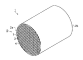
本発明の一実施形態のハニカム構造体1は、図1〜図4に示すように、流体の流路を形成する一方の端面2aから他方の端面2bまで延びる多角形の複数のセル3を区画形成する格子状の隔壁4を備えるハニカム構造部5と、ハニカム構造部5を構成する複数のセル3において、所定のセル3の一方の開口端部6a及び残余のセル3の他方の開口端部6bをそれぞれ規則正しい所定の配列で閉塞してなる目封止部7とを有している。本実施形態の目封止部7は、互いに隣接するセル3の一方の開口端部6a(または他方の開口端部6b)をそれぞれ一つおきに交互に目封止して形成されている(例えば、図2参照)。
As shown in FIGS. 1 to 4, the honeycomb structure 1 of one embodiment of the present invention partitions a plurality of polygonal cells 3 extending from one
ハニカム構造体1は、骨材8、当該骨材8と異なる材質の結合材9、及び結合助剤13を混合及び混練した成形材料10を、押出成形機を用いて所望のハニカム形状のハニカム成形体に押出成形し(成形工程)、得られたハニカム成形体を所定の焼成温度で焼成する(焼成工程)ことによって製造されるものである。製造されたハニカム構造体1を用い、DPFが作製される。このDPFの一方の端部からディーゼルエンジンの排ガスを導入することにより、当該排ガスが隔壁4を透過する間に排ガス中に含まれるスス等の粒子状物質を、多孔質の隔壁4によって捕集することができる。
The honeycomb structure 1 is formed by forming an
ハニカム構造体1を構成する格子状の隔壁4は、骨材8及び結合材9から主に構成され、骨材として炭化珪素(SiC)が使用されている。ここで、骨材8の平均粒径は10〜60マイクロメートルの範囲のものである。一方、結合材9として金属珪素(Si)、コージェライトが使用され、骨材8と比較して平均粒径が小さなものが使用されている。これにより、骨材8である炭化珪素が結合材である金属珪素等によって結合され、隔壁4が形成される。
Case child-like partition walls 4 that make up the honeycomb structure 1 is mainly composed of
更に,本実施形態のハニカム構造体1は、隔壁4の隔壁表面4aから隔壁裏面4cに至る隔壁厚さT(図3参照)において、当該隔壁表面4aから15%の深さまでの隔壁内部4bの領域(表面領域11)の気孔率に係る表面気孔率Aと、隔壁厚さTの隔壁表面4aの15%から50%の深さまでの隔壁内部4bの領域(内部領域12)の気孔率に係る内部気孔率Bとがそれぞれ異なる値を示し、表面気孔率Aに対して内部気孔率Bの値が大きい。すなわち、表面領域11に対して内部領域12の気孔率が高い。
Furthermore, in the honeycomb structure 1 of the present embodiment, the partition wall interior 4b from the
上記の表面気孔率Aは10%〜50%の範囲であり、更に好ましくは30%〜40%の範囲である。一方、内部気孔率Bは20%〜75%の範囲であり、更に好ましくは35%〜45%の範囲である。また、表面気孔率A及び内部気孔率Bの関係は、内部気孔率Bから表面気孔率Aを減じた差が1.5%を超える(“内部気孔率B−表面気孔率A>1.5%”)ものである。 The surface porosity A is in the range of 10% to 50%, more preferably in the range of 30% to 40%. On the other hand, the internal porosity B is in the range of 20% to 75%, more preferably in the range of 35% to 45%. The relationship between the surface porosity A and the internal porosity B is such that the difference obtained by subtracting the surface porosity A from the internal porosity B exceeds 1.5% (“internal porosity B−surface porosity A> 1.5 % ").
ハニカム構造体1において、隔壁4の表面領域11の平均細孔径に係る表面平均細孔径Cと、内部領域12の平気細孔径に係る内部平均細孔径Dは異なる値を示し、表面平均細孔径Cに対して内部平均細孔径Dの値が大きい。ここで、平均細孔径とは、表面領域11及び内部領域12のそれぞれの各気孔の平均分布に基づいて算出されるものである。すなわち、表面領域11に対して内部領域12の平均細孔径が大きくなり、上記した気孔率の値とともに、大きな孔径の気孔が内部領域12を占めている。
In the honeycomb structure 1, the surface average pore diameter C related to the average pore diameter of the
上記の表面平均細孔径Cは5〜40マイクロメートルの範囲であり、更に好ましくは10〜25マイクロメートルの範囲である。一方、内部平均細孔径Dは8〜50マイクロメートルの範囲であり、更に好ましくは20〜30マイクロメートルの範囲である。また、表面平均細孔径C及び内部平均細孔径Dの関係は、内部平均細孔径Dから表面平均細孔径Cを減じた差が0.5マイクロメートル超の(“内部平均細孔径D−表面平均細孔径C>0.5マイクロメートル”)ものである。 The surface average pore diameter C is in the range of 5 to 40 micrometers, more preferably in the range of 10 to 25 micrometers. On the other hand, the internal average pore diameter D is in the range of 8 to 50 micrometers, more preferably in the range of 20 to 30 micrometers. Further, the relationship between the surface average pore diameter C and the internal average pore diameter D is such that the difference obtained by subtracting the surface average pore diameter C from the internal average pore diameter D is more than 0.5 micrometers ("internal average pore diameter D-surface average Pore diameter C > 0.5 micrometer ").
成形材料10は、骨材8、結合材9、及び結合助剤13を混合及び混練して得られる(成形材料形成工程)。結合助剤13としては、異方性粒子が用いられ、当該異方性粒子は、例えば、板状(薄板状)のマイカ、或いは棒状(繊維状)のAl−Siファイバー等である。ここで、結合助剤13は、長径方向の平均粒径が少なくとも5マイクロメートル以上のサイズであり、更に、短径方向の平均粒径に対する長径方向の平均粒径のアスペクト比が5以上のものが使用される。なお、ファイバーの場合は、直径を上記短径として扱う。更に、係る結合助剤13は、添加される結合材9(例えば、金属珪素)の融点よりも低融点のものが使用され、配合比率は、3.0wt.%〜10.0wt.%の範囲に設定されている。
The
成形材料10に使用される骨材8、結合材9、及び結合助剤13の平均粒径及び融点の関係をまとめると、平均粒径の大きさは、結合助剤13>結合材9の順であり、融点は、骨材8>結合材9>結合助剤13の順で高くなる。ハニカム構造体1を製造する焼成工程において、焼成温度は結合材9の融点よりも高い温度で焼成が行われる。
When the relationship between the average particle diameter and the melting point of the
本実施形態のハニカム構造体1は、上記構成を採用することにより、粒子状物質(スス)の捕集効率を向上させるとともに、圧力損失の増大を抑制し、更に粒子状物質の捕集漏れ個数濃度を低く抑えることができる。特に、成形材料10に含まれる結合材9に対し、マイカ等の異方性粒子を結合助剤13として所定の配合比率で添加し、結合材9の融点よりも高い焼成温度で焼成を行うことにより、ハニカム構造体1の隔壁4の内部領域12の内部気孔率B及び内部平均細孔径Dに対し、表面領域11の表面気孔率A及び表面平均細孔径Cがそれぞれ小さな値を示すものとすることができる。
The honeycomb structure 1 of the present embodiment adopts the above configuration to improve the collection efficiency of particulate matter (soot), suppress an increase in pressure loss, and further collect the number of particulate matter collection leaks. The concentration can be kept low. In particular, anisotropic particles such as mica are added as a binding
すなわち、異方性粒子として結合助剤13を成形材料10に添加することで、隔壁4の表面領域11及び内部領域12のそれぞれの気孔率及び平均細孔径を制御し、上述した関係を示すようにすることができる。
That is, by adding the binding
これにより、ハニカム構造体1を用いて形成されたDPFに導入された排ガス中の粒子状物質は、平均細孔径と気孔率が小さい隔壁4の隔壁表面4aに捕集されやすくなる。すなわち、捕集効率が高められるとともに、粒子状物質が隔壁4の隔壁内部4bの気孔を閉塞しにくいため、圧力損失の増大を抑制できる。更に、隔壁表面4aの気孔率が低いため、隔壁4全体としても熱容量を大きくでき、最大スス堆積量を増大させることができる。本実施形態のハニカム構造体1は、隔壁4の全体が低気孔率化するものではなく、隔壁表面4aから15%の深さまでの表面領域11が限定的に低気孔率化され、15%から50%の深さまでの内部領域12は、表面領域11に対して内部気孔率B及び内部平均細孔径Dの値は一定のレベルに保たれる。
Thereby, the particulate matter in the exhaust gas introduced into the DPF formed using the honeycomb structure 1 is easily collected on the
スス等の粒子状物質は隔壁表面4aに堆積層(図示しない)を形成して隔壁内部4bの気孔(細孔)の閉塞を防止できるので、ハニカム構造体1に導入された排ガスによる圧力損失の増大を抑制することができる。隔壁内部4bの平均細孔径と気孔率が大きいことも、隔壁内部4bの気孔の閉塞防止に寄与している。なお、隔壁表面4aの50%〜85%(隔壁裏面4cの15%から50%に相当)の深さ領域(図示しない)及び隔壁表面4aの85%から100%(隔壁裏面4cから15%)の深さの領域(図示しない)は、それぞれ上記内部領域12及び表面領域11と同一の構成を示している。
Since particulate matter such as soot can form a deposition layer (not shown) on the
本実施形態のハニカム構造体の製造方法において、結合助剤13として異方性粒子を成形材料10に添加し、結合材9及び結合助剤13の融点よりも高い焼成温度で焼成を行った場合の骨材8、結合材9、及び結合助剤13の想定挙動メカニズムを、図4に基づいて以下に説明する。図4において、骨材8として炭化珪素、結合材9として金属珪素、及び結合助剤13として薄板状のマイカを使用したものについて例示する。
In the method for manufacturing a honeycomb structure of the present embodiment, when anisotropic particles are added to the
金属珪素(結合材9)の融点は約1300℃であり、マイカ(結合助剤13)の融点は金属珪素よりも低い1200℃〜1300℃の間である。更に、炭化珪素(骨材8)の融点は金属珪素よりも高い。なお、説明を簡略化するため、成形材料10において上記三成分以外の原料については図示を省略する。
The melting point of metallic silicon (binding material 9) is about 1300 ° C., and the melting point of mica (binding aid 13) is between 1200 ° C. and 1300 ° C., which is lower than that of metallic silicon. Furthermore, the melting point of silicon carbide (aggregate 8) is higher than that of metallic silicon. In addition, in order to simplify description, illustration is abbreviate | omitted about raw materials other than the said three components in the
始めに、骨材8、結合材9、及び結合助剤13の三成分を所定の配合比率で混合及び混練し、上記三成分が均一に混ざった成形材料10を形成する(成形材料形成工程、結合助剤添加工程)。このとき、結合材9の平均粒径に対し、結合助剤13の平均粒径が大きくなるように設定されている。そのため、結合材9の少なくとも一部が平均粒径の大きな結合助剤13と接触し、拘束された状態となる(図4における焼成前参照。)。この状態で押出成形機を用いて押出成形され、ハニカム成形体が形成される(成形工程)。得られたハニカム成形体は焼成工程に送出される。
First, the three components of the
焼成工程まで送出されたハニカム成形体は、所定の焼成温度に設定された焼成炉内に投入される。本実施形態において、焼成温度は1300℃以上に設定されている。焼成炉の炉内部に投入されたハニカム成形体を構成する成形材料10は、始めに最も融点の低い結合助剤13が溶融を開始する。このとき、溶融した結合助剤13は、隔壁内部4bから隔壁表面4a(図4における紙面上方に相当)若しくは隔壁裏面4c(図4における紙面下方に相当)に向かって移動する。
The honeycomb formed body sent to the firing step is put into a firing furnace set at a predetermined firing temperature. In the present embodiment, the firing temperature is set to 1300 ° C. or higher. In the
このとき、結合助剤13の移動に併せて、当該結合助剤13に拘束された結合材9が、結合助剤13の移動方向M(図4参照)に沿って移動する力が作用する。これにより、隔壁内部4bの内部領域12から隔壁表面4a(または隔壁裏面4c)の近傍の表面領域11に結合助剤13及び結合材9が移動する。
At this time, in conjunction with the movement of the
更に、焼成温度が高くなり、結合材9の融点を超えると、当該結合材9が溶融する。結合助剤13及び結合材9が溶融することにより、これらが隔壁表面4a(または隔壁裏面4c)に移動した状態で骨材8が結合される。焼成炉内から排出されたハニカム構造体1は徐々に室温付近まで冷却される。これにより、隔壁表面4a等に移動した結合助剤13及び結合材9が凝固し、炭化珪素の骨材8を互いに結合する結合部14が形成されると推察される。
Furthermore, when the firing temperature is increased and the melting point of the
その結果、隔壁表面4a(または隔壁裏面4c)の表面領域11が、隔壁内部4bの内部領域12と比べて緻密化した構造を呈し、隔壁内部4bに多く、かつ大きな孔径の細孔が形成された隔壁4が形成される。したがって、表面領域11及び内部領域12において、気孔率及び平均細孔径を異ならせるように制御できる。
As a result, the
以上、説明したように、本実施形態のハニカム構造体1、及びハニカム構造体の製造方法によれば、アスペクト比が5以上のマイカ等の結合助剤13を添加した成形材料10を用い、ハニカム構造体1を製造することができる。これにより、隔壁4の表面領域11及び内部領域12において、気孔率及び平均細孔径をそれぞれ異ならせることができ、かつ内部領域12に対する表面領域11の気孔率及び平均細孔径の差を一定の値以上とすることができる。その結果、圧力損失の増加を抑制し、最大スス堆積量を向上させ、高い耐久性を備えるとともに、粒子状物質の捕集効率を高め、欧州等の粒子状物質の個数ベースの排出規制をクリアすることが可能となる。
As described above, according to the honeycomb structure 1 and the manufacturing method of the honeycomb structure of the present embodiment, the
以下、本発明のハニカム構造体及びハニカム構造体の製造方法の実施例について説明するが、本発明のハニカム構造体及びハニカム構造体の製造方法は、これらの実施例に限定されるものではない。 Hereinafter, examples of the honeycomb structure of the present invention and the manufacturing method of the honeycomb structure will be described, but the honeycomb structure and the manufacturing method of the honeycomb structure of the present invention are not limited to these examples.
(1)ハニカム構造体
骨材、結合材、及び異方性粒子からなる結合助剤を所定の比率で配合し、有機バインダー、界面活性剤及び水を加えて均一に混合及び混練し、得られた成形材料を、押出成形機を利用して押出成形し、ハニカム成形体を得た。得られたハニカム成形体を切断及び乾燥後、目封止を行い、予め規定された焼成温度で焼成を行うことにより、セグメント状のハニカム構造体を得た。セグメント状のハニカム構造体を接合材を用いて接合した後、外周研削、外周コートを行うことで、本発明における実施例及び比較例のハニカム構造体を作製した。
(1) Honeycomb structure Obtained by blending a binder, a binder, and a binding aid composed of anisotropic particles at a predetermined ratio, adding an organic binder, a surfactant and water, and mixing and kneading them uniformly. The formed molding material was extruded using an extrusion molding machine to obtain a honeycomb molded body. The obtained honeycomb formed body was cut and dried, plugged, and fired at a firing temperature defined in advance to obtain a segmented honeycomb structure. After joining the segmented honeycomb structures using a bonding material, outer peripheral grinding and outer peripheral coating were performed, so that the honeycomb structures of Examples and Comparative Examples of the present invention were manufactured.
本実施例において、ハニカム構造体は、実施例1〜17、及び、比較例1〜11において、いずれも骨材として炭化珪素を使用するものであり、結合材として実施例1〜8、実施例15〜17、比較例1、比較例3〜7、及び比較例10〜11において金属珪素を使用し、実施例9〜14、比較例2、及び比較例8,9においてコージェライトを使用するものである。骨材及び結合材の比率は、いずれも75/25である。更に、結合助剤として、実施例1〜14、及び比較例6〜11においてマイカを使用し、実施例15〜17においてAl−Siファイバーを使用し、比較例3〜5においてタルクを使用した。また、比較例1,2については、結合助剤を成形材料に添加しないものである。実施例及び比較例のハニカム構造体は、いずれも直径は144mm、長さは152mmであり、セル構造の隔壁厚さは0.3mm、セル密度は46.5セル/cm2である。 In the present example, the honeycomb structure was obtained by using silicon carbide as an aggregate in Examples 1 to 17 and Comparative Examples 1 to 11 , and Examples 1 to 8 and Examples as binders. Metallic silicon is used in 15 to 17, Comparative Example 1, Comparative Examples 3 to 7, and Comparative Examples 10 to 11 , and cordierite is used in Examples 9 to 14, Comparative Example 2, and Comparative Examples 8 and 9. It is. The ratios of aggregate and binder are both 75/25. Further, as binding aids, mica was used in Examples 1 to 14 and Comparative Examples 6 to 11 , Al-Si fibers were used in Examples 15 to 17, and talc was used in Comparative Examples 3 to 5. In Comparative Examples 1 and 2, no binding aid is added to the molding material. The honeycomb structures of Examples and Comparative Examples each have a diameter of 144 mm and a length of 152 mm, a partition wall thickness of the cell structure is 0.3 mm, and a cell density is 46.5 cells / cm 2 .
上記骨材及び結合材の比率(75/25)、骨材の粒径(μm)、結合助剤の粒子形状、種類、長軸側粒径(μm)、配合比率(wt.%)と、得られたハニカム構造体の表面領域及び内部領域のそれぞれの気孔率(%)、表面領域及び内部領域のそれぞれの平均細孔径(μm)、圧力損失(kPa)、PN漏れ個数(個)の測定結果をまとめたものを下記表1に示す。また、実施例及び比較例において骨材として使用した炭化珪素と、結合材として使用した金属珪素、コージェライトにおけるアルミナ、及びコージェライトにおけるタルクと、結合助剤として使用した2種類のマイカ、タルク、及びAl−Siファイバーとのそれぞれの平均粒径についてまとめたものを下記表2に示す。なお、コージェライトにおけるタルク、マイカ、結合助剤としてのタルク、及びAl−Siファイバーに介しては、長径方向及び短径方向のそれぞれの平均粒径及び短径に対する長径の平均粒径の比であるアスペクト比についても併せて示している。なお、コージェライトを結合材とする場合、成形材料としてはアルミナとタルクであり、焼成工程でこれらが反応してコージェライトを形成する。タルクは結合材の原料であるとともに、異方性粒子として結合助剤でもある。 Ratio of aggregate and binder (75/25), aggregate particle size (μm), particle shape and type of binding aid, major axis side particle size (μm), blending ratio (wt.%), Measurement of porosity (%) of each surface region and internal region of the obtained honeycomb structure, average pore diameter (μm), pressure loss (kPa), and number of PN leaks (pieces) of the surface region and internal region The results are summarized in Table 1 below. Further, silicon carbide used as an aggregate in Examples and Comparative Examples, metal silicon used as a binder, alumina in cordierite, talc in cordierite, and two types of mica and talc used as a binding aid, Table 2 below summarizes the average particle diameters of Al and Si fibers. In addition, talc in cordierite, mica, talc as a binding aid, and Al-Si fiber, the average particle diameter in the major axis direction and the minor axis direction and the ratio of the average diameter of the major axis to the minor axis A certain aspect ratio is also shown. When cordierite is used as a binder, the molding materials are alumina and talc, and these react to form cordierite in the firing step. Talc is a raw material for the binder and is also a binding aid as anisotropic particles.

(2)気孔率の算出
気孔率は、隔壁の表面領域及び内部領域のそれぞれの隔壁断面の走査型電子顕微鏡(SEM)写真を撮影し、市販の画像解析ソフトを用いて算出した。更に具体的に説明すると、隔壁断面のSEM画像を画像解析ソフトを用いて、二極化処理し、それぞれの表面領域及び内部領域における隔壁の部分(細孔以外の部分に相当)と細孔の部分の面積を計測し、得られた面積の計測値に基づいて各領域における気孔率を算出した。
(2) Calculation of porosity
The porosity was calculated using a commercially available image analysis software by taking a scanning electron microscope (SEM) photograph of each partition wall cross section of the surface area and the internal area of the partition wall. More specifically, the SEM image of the cross section of the partition wall is bipolarized using image analysis software, and the partition wall portions (corresponding to portions other than the pores) in each surface region and internal region and the pores The area of the part was measured, and the porosity in each region was calculated based on the measured area value.
(3)平均細孔径の算出
平均細孔径は、気孔率の算出と同様に、撮影された隔壁断面のSEM画像に基づき、
画像解析ソフトを用いて、二極化処理し、それぞれの表面領域及び内部領域における各細
孔の細孔径を計測し、得られた細孔径から平均細孔径を算出した。
(3) calculating an average pore diameter of the average pore diameter, as well as the calculation of the porosity, based on the SEM image of the captured septum wall section,
Bipolarization processing was performed using image analysis software, the pore diameter of each pore in each surface region and internal region was measured, and the average pore diameter was calculated from the obtained pore diameter.
(4)圧力損失の測定
実施例及び比較例のハニカム構造体からDPFを作製し、室温(25℃)の空気を10Nm3/分の流量で流した際のDPFの入口(上流側)及び出口(下流側)のそれぞれの圧力を計測し、その圧力差を算出することにより圧力損失を求めた。求められた圧力損失の測定値が1.0kPa以下のものを「良」と判定し、1.0kPaを超えるものを「不可」と判定した。
(4) Measurement of pressure loss DPF was produced from the honeycomb structures of the examples and comparative examples, and DPF inlet (upstream side) and outlet when air at room temperature (25 ° C.) was flowed at a flow rate of 10 Nm 3 / min. Each pressure on the (downstream side) was measured, and the pressure loss was calculated by calculating the pressure difference. A measured pressure loss value of 1.0 kPa or less was determined as “good”, and a pressure value exceeding 1.0 kPa was determined as “impossible”.
(5)PN漏れ個数の測定
実施例及び比較例のそれぞれのハニカム構造体から形成されたDPFを、排気量2.0リットルのディーゼルエンジンが搭載された乗用車の排気系に取り付けた。この乗用車をNEDC(New European Driving Cycle)モードで走行させた際のDPFの出口(下流側)における粒子状物質の個数累計からPN漏れ個数を測定した。なお、粒子状物質の個数の測定は、欧州経済委員会における自動車基準調和世界フォーラムの排出ガスエネルギー専門家会議による粒子測定プログラム(略称「PMP」)によって提案された手法に従って行った。ここで、PN漏れ個数の測定値が、1.0×10⁸未満を「良」と判定し、1.0×10⁸以上、1.0×10⁹以下を「可」と判定し、1.0×10⁹を超えるものを「不可」と判定した。
(5) Measurement of the number of PN leaks The DPF formed from the honeycomb structures of the examples and comparative examples was attached to the exhaust system of a passenger car equipped with a 2.0-liter diesel engine. The number of PN leaks was measured from the cumulative number of particulate matter at the outlet (downstream side) of the DPF when this passenger car was driven in the NEDC (New European Driving Cycle) mode. The number of particulate matter was measured according to the method proposed by the particle measurement program (abbreviated as “PMP”) by the Emissions Energy Experts Meeting of the World Economic Forum for Automobile Standards at the European Economic Commission. Here, if the measured value of the number of PN leaks is less than 1.0 × 10 8, it is determined as “good”, and 1.0 × 10 8 or more and 1.0 × 10 9 or less are determined as “possible”. Those exceeding 0.0 × 10 9 were judged as “impossible”.
(6)ハニカム構造体の評価
表1に示すとおり、本願発明の実施例1〜17のハニカム構造体に基づいて作製されたDPFは、圧力損失及びPN漏れ個数のいずれの判定結果において、良または可の評価であり、一方、比較例1〜11のハニカム構造体に基づいて作製されたDPFは、圧力損失及びPN漏れ個数の少なくともいずれか一方が不可の判定であった。以下、各項目について詳細を説明する。
(6) Evaluation of Honeycomb Structure As shown in Table 1, the DPF produced based on the honeycomb structures of Examples 1 to 17 of the present invention is good or bad in any judgment result of the pressure loss and the number of PN leaks. On the other hand, the DPF manufactured based on the honeycomb structures of Comparative Examples 1 to 11 was judged that at least one of the pressure loss and the number of PN leaks was not possible. Details of each item will be described below.
(6−1)結合助剤の有無
骨材及び結合材に対して所定の配合比率の結合助剤を添加することにより(実施例1等参照)、圧力損失及びPN漏れ個数のいずれの項目においても「良」または「可」の判定結果が得られた。これに対し、結合助剤を添加しない場合(比較例1、2)、圧力損失の値が結合助剤を添加した場合と比べて高くなり、判定基準の1.0kPaを超えるものとなった。これにより、結合助剤の添加の有効性が示された。
(6-1) Presence / absence of binding aid By adding a binding aid having a predetermined blending ratio to the aggregate and the binding material (see Example 1), in any of the items of pressure loss and number of PN leaks The result of “good” or “good” was also obtained. On the other hand, when the binding aid was not added (Comparative Examples 1 and 2), the pressure loss value was higher than that when the binding aid was added, exceeding the criterion of 1.0 kPa. This demonstrated the effectiveness of adding a binding aid.
(6−2)骨材の粒径
使用する骨材(炭化珪素)の粒径を、それぞれ10μm、28μm、及び60μmに変化させ、配合比率等のその他の条件を一定にした場合、10μm〜60μmの間で(実施例2,4,5)、各項目において良または可の判定結果を得た。これにより、骨材の粒径は、10μm〜60μmの範囲が好適であることが確認された。
(6-2) If the bone material used particle size of the aggregate particle size of (silicon carbide), which respectively 1 0 .mu.m, changing 28 .mu.m, and 60 microns m, and the other conditions such as the mixing ratio constant Between 10 μm and 60 μm (Examples 2, 4 and 5), good or acceptable determination results were obtained for each item . This ensures that the particle size of the aggregate was confirmed range 10μm~60μm are preferred.
(6−3)結合材の種類
結合材として、本実施例では金属珪素(実施例1〜3等)及びコージェライト(実施例9〜14等)をそれぞれ使用した。この場合、圧力損失及びPN個数漏れのいずれの評価項目においても、特に結合材の種類における大きな差異は認められず、金属珪素及びコージェライトを結合材として使用可能なことが確認された。
(6-3) Types of binders In this example, metallic silicon (Examples 1 to 3 and the like) and cordierite (Examples 9 to 14 and the like) were used as the binders. In this case, in any of the evaluation items of pressure loss and PN number leakage, no significant difference was observed in the type of the binder, and it was confirmed that metallic silicon and cordierite can be used as the binder.
(6−4)結合助剤の種類
使用する結合助剤(異方性粒子)として、長軸側粒径のそれぞれ異なる二種類のマイカ、Al−Siファイバー、及びタルクを用いた。これらの結果から、その他の条件を同一とした場合、結合助剤としてタルクを使用した場合、各項目について上記判定基準を満たすことができず、一方、マイカ及びAl−Siファイバーは、いずれも良または可の判定結果を得た。更に、マイカの粒径の違い(実施例1〜3及び実施例4〜6等参照)によって、圧力損失及びPN漏れ個数に大きな差異は認められなかった。これにより、結合助剤として、マイカ及びAl−Siファイバーが有効であることが確認された。
(6-4) Types of Binding Aids As the binding aids (anisotropic particles) to be used, two types of mica, Al—Si fibers, and talc, each having a different major axis side particle size, were used. From these results, when other conditions are the same, and when talc is used as a binding aid, the above criteria for each item cannot be satisfied, while mica and Al-Si fiber are both good. Or a good judgment result was obtained. Furthermore, there was no significant difference in pressure loss and the number of PN leaks due to the difference in the particle size of mica (see Examples 1 to 3 and Examples 4 to 6). Thereby, it was confirmed that mica and Al-Si fiber are effective as a binding aid.
(6−5)結合助剤の配合比率(表面気孔率及び内部気孔率)
骨材の粒径等のその他条件を同一とし、骨材及び結合材に対する結合助剤の配合比率をそれぞれ3.0wt.%、5.0wt.%、及び10.0wt.%に変化させた場合(実施例1〜3、実施例6〜8、実施例9〜11、及び、実施例12〜14)、配合比率が高くなるにつれて、表面気孔率の値が低下し、これに対して内部気孔率の値が上昇する傾向が認められた。すなわち、結合助剤を多く添加することによって、ハニカム構造体の内部領域に多くの空隙(空孔)が認められるようになり、表面領域の気孔率がそれほど高くなくなることが示された。
(6-5) Blending ratio of binding aid (surface porosity and internal porosity)
Other conditions such as the particle size of the aggregate are the same, and the blending ratio of the binding aid to the aggregate and the binder is 3.0 wt. %, 5.0 wt. %, And 10.0 wt. % (Examples 1-3, Examples 6-8, Examples 9-11, and Examples 12-14), the value of the surface porosity decreases as the blending ratio increases, On the other hand, there was a tendency for the value of internal porosity to increase. That is, it was shown that by adding a large amount of binding aid, many voids (voids) are recognized in the internal region of the honeycomb structure, and the porosity of the surface region is not so high.
一方、結合助剤の配合比率が低い場合(1.0wt.%、比較例6〜9)、圧力損失が大きくなる傾向が認められ、同様に結合助剤の配合比率が高い場合(15.0wt.%、比較例10,11)でも圧力損失が大きくなる傾向が示された。 On the other hand, when the blending ratio of the binding aid is low (1.0 wt.%, Comparative Examples 6 to 9), a tendency to increase the pressure loss is recognized, and when the blending ratio of the binding aid is high (15.0 wt. %, Comparative Examples 10 and 11) also showed a tendency for pressure loss to increase.
(6−6)結合助剤の配合比率(表面平均細孔径及び内部平均細孔径)
骨材の粒径等のその他の条件を同一とし、結合助剤の配合比率を変化させた場合(実施例1〜3、実施例6〜8、実施例9〜11、及び、実施例12〜14)、配合比率が高くなるにつれて、表面平均細孔径の値が低下し、一方、内部平均細孔径の値が上昇することが確認された。この傾向は、上記(6−5)で示した表面気孔率及び内部気孔率と配合比率との関係と同様のものである。
(6-6) Blending ratio of binding aid (surface average pore diameter and internal average pore diameter)
When other conditions such as the particle size of the aggregate are the same and the blending ratio of the binding aid is changed (Examples 1 to 3, Examples 6 to 8, Examples 9 to 11, and Examples 12 to 14) It was confirmed that the value of the surface average pore diameter decreased as the blending ratio increased, while the value of the internal average pore diameter increased. This tendency is the same as the relationship between the surface porosity, the internal porosity, and the blending ratio shown in (6-5) above.
(6−7)評価のまとめ
骨材の粒径等のその他の条件を同一とし、結合助剤の配合比率を変化させた場合(実施例1〜3、実施例6〜8、実施例9〜11、及び、実施例12〜14)、配合比率が5.0wt.%添加したものが、圧力損失がそれぞれ最も小さな値を示した(実施例1〜3における実施例2、実施例6〜8における実施例7、実施例9〜11における実施例10、実施例12〜14における実施例13参照。)。これにより、本実施例において、ハニカム構造体の隔壁の圧力損失の低減のためには、5.0wt.%の結合助剤を添加することが好適であると確認された。一方、PN漏れ個数は、結合助剤の配合比率に応じて比例し、配合比率が高い場合(10wt.%)、それぞれ最も小さな値を示し(実施例3、実施例8、実施例11、実施例14参照)、一方、配合比率が低い場合(3.0wt.%)、それぞれ最も大きな値を示した(実施例1、実施例6、実施例9、実施例12参照)。
これにより、結合助剤の配合比率に応じて圧力損失の低減化及びPN漏れ個数を制御することができる。
(6-7) Summary of evaluation When other conditions such as the particle size of the aggregate are made the same and the blending ratio of the binding aid is changed (Examples 1 to 3, Examples 6 to 8, and Examples 9 to 11 and Examples 12 to 14), the blending ratio is 5.0 wt. %, The pressure loss showed the smallest value (Example 2 in Examples 1 to 3, Example 7 in Examples 6 to 8, Example 10 in Examples 9 to 11, and Example 12). See Example 13 in -14). Thereby, in this example, in order to reduce the pressure loss of the partition walls of the honeycomb structure, 5.0 wt. % Of a binding aid has been found to be suitable. On the other hand, the number of PN leaks is proportional to the blending ratio of the binding aid, and when the blending ratio is high (10 wt.%), Each shows the smallest value (Example 3, Example 8, Example 11, implementation). On the other hand, when the blending ratio was low (3.0 wt.%), The largest values were shown (see Example 1, Example 6, Example 9, and Example 12).
Thereby, reduction of pressure loss and the number of PN leaks can be controlled according to the blending ratio of the binding aid.
更に、配合比率は、表面領域及び内部領域における表面気孔率及び内部気孔率、表面平均細孔径及び内部平均細孔径の値にそれぞれ寄与することが示された。すなわち、骨材として実施例1〜17において、結合助剤の配合比率が高くなるにつれて、表面気孔率及び表面平均細孔径の値は徐々に小さくなるように変化し、一方、内部気孔率及び内部平均細孔率の値は徐々に大きくなるように変化することが確認された。そのため、表面気孔率及び内部気孔率の差、及び、表面平均細孔径及び内部平均細孔径の差は、それぞれ異方性粒子の配合比率が高いもの(10wt.%)が、最も高い値を示し、異方性粒子の配合比率が低いもの(3.0wt.%)が、最も低い値を示すこととなった。すなわち、異方性粒子を多く配合することにより、表面領域及び内部領域の気孔率及び平均細孔径の差が大きくなるように制御することができる。 Furthermore, it was shown that the compounding ratio contributes to the values of the surface porosity and the internal porosity, the surface average pore diameter and the internal average pore diameter in the surface region and the internal region, respectively. That is, in Examples 1 to 17 as an aggregate, as the mixing ratio of the binding aid is high, the value of the surface porosity and surface average pore size varies so as to gradually become smaller, whereas the inner Bukit porosity It was also confirmed that the value of the internal average porosity changes so as to gradually increase. Therefore, the difference between the surface porosity and the internal porosity and the difference between the surface average pore diameter and the internal average pore diameter are the highest when the compounding ratio of anisotropic particles is high (10 wt.%). The one with a low blending ratio of anisotropic particles (3.0 wt.%) Showed the lowest value. That is, by adding a large amount of anisotropic particles, it is possible to control so as to increase the difference between the porosity and the average pore diameter of the surface region and the internal region.
これに対し、異方性粒子を結合助剤として添加しない場合(比較例1,2)、圧力損失及びPN漏れ個数においてもいずれも良好な結果を得ることができなかった。すなわち、本発明における異方性粒子を結合材助剤として添加することの有効性が示される。結合助剤を加える場合であってもタルクでは、圧力損失の値が増大し、異方性粒子の添加による効果を得ることができなかった(比較例3〜5)。更に、結合材に対して添加する異方性粒子の配合比率が低い場合(1.0wt.%、比較例6〜9)、圧力損失及びPN漏れ個数のいずれの評価項目において良好な結果を得ることができなかった。すなわち、表面領域及び内部領域の間に1.5%超の気孔率の差を形成することができなかった。そのため、実施例に示すような効果を奏することができない。 On the other hand, when anisotropic particles were not added as a binding aid (Comparative Examples 1 and 2), good results could not be obtained in both pressure loss and the number of PN leaks. That is, the effectiveness of adding the anisotropic particles in the present invention as a binder aid is shown. Even when a binding aid is added, the value of pressure loss increases with talc, and the effect of adding anisotropic particles cannot be obtained (Comparative Examples 3 to 5). Furthermore, when the blending ratio of the anisotropic particles added to the binder is low (1.0 wt.%, Comparative Examples 6 to 9), good results are obtained in any evaluation items of pressure loss and the number of PN leaks. I couldn't. That is, a porosity difference of more than 1.5% could not be formed between the surface region and the inner region. Therefore, the effect as shown in the embodiment cannot be achieved.
更に、結合材に対して添加する異方性粒子の配合比率が過剰過多の場合(比較例10,11)、いずれも圧力損失が大きくなり、実用上の使用をすることができない。しかしながら、係る場合、内部気孔率及び表面気孔率、及び、内部平均細孔径及び表面平均細孔径の値が最も大きくなることが示された。これらの結果からも異方性粒子を骨材及び結合材に添加しハニカム成形体を形成する有用性が示された。 Furthermore, when the blending ratio of the anisotropic particles added to the binder is excessive (Comparative Examples 10 and 11), the pressure loss becomes large in any case and cannot be used practically. However, in such a case, it was shown that the values of the internal porosity and the surface porosity, and the internal average pore diameter and the surface average pore diameter become the largest. These results also showed the usefulness of adding anisotropic particles to aggregates and binders to form honeycomb formed bodies.
本発明のハニカム構造体、及びハニカム構造体の製造方法は、自動車、化学、電力、鉄鋼等の様々な分野において、触媒装置用の担体、又はフィルタとして好適に利用することができるハニカム構造体の製造に利用することができる。特に、ディーゼルエンジンの排ガスに含まれる粒子状物質を捕捉するためのDPFとしての使用が好適である。 The honeycomb structure of the present invention and the method for manufacturing the honeycomb structure are provided in a honeycomb structure that can be suitably used as a carrier for a catalyst device or a filter in various fields such as automobiles, chemistry, electric power, and steel. Can be used for manufacturing. In particular, the use as a DPF for capturing particulate matter contained in exhaust gas from a diesel engine is suitable.
1:ハニカム構造体、2a:一方の端面、2b:他方の端面、3:セル、4:隔壁、4a:隔壁表面、4b:隔壁内部、4c:隔壁裏面、5:ハニカム構造部、6a:一方の開口端部、6b:他方の開口端部、7:目封止部、8:骨材、9:結合材、10:成形材料、11:表面領域、12:内部領域、13:結合助剤(異方性粒子)、14:結合部、M:結合助剤(異方性粒子)および結合材の移動方向、T:隔壁厚さ。 1: honeycomb structure, 2a: one end face, 2b: other end face, 3: cell, 4: partition wall, 4a: partition wall surface, 4b: inside partition wall, 4c: partition wall back surface, 5: honeycomb structure part, 6a: one 6b: the other open end, 7: plugging portion, 8: aggregate, 9: binder, 10: molding material, 11: surface region, 12: inner region, 13: binding aid (Anisotropic particles), 14: bonding portion, M: bonding auxiliary agent (anisotropic particles) and moving direction of the bonding material, T: partition wall thickness.
Claims (2)
前記隔壁は、
骨材及び前記骨材と異なる材質の結合材を用いて多孔質に形成され、
前記隔壁の隔壁表面から隔壁厚さの15%の深さまでの表面領域の表面気孔率と、前記隔壁表面から前記隔壁厚さの15%から50%の深さまでの内部領域の内部気孔率とがそれぞれ異なり、
前記内部気孔率から前記表面気孔率を減じた差が、1.5%超から13%までとなる関係を示し、
前記表面気孔率は、
30%〜37%の範囲であり、
前記内部気孔率は、
35%〜44%の範囲であり、
かつ、
前記内部領域の内部平均細孔径から前記表面領域の表面平均細孔径を減じた差が、0.5マイクロメートル超から14マイクロメートルまでとなる関係を示し、
前記表面平均細孔径は、
13〜22マイクロメートルの範囲であり、
前記内部平均細孔径は、
20〜28マイクロメートルの範囲であるハニカム構造体。 A grid-shaped partition wall that partitions and forms a plurality of polygonal cells extending from one end surface to the other end surface forming a fluid flow path;
The partition is
It is formed to be porous using an aggregate and a binder of a material different from the aggregate,
The surface porosity of the surface region from the partition wall surface to a depth of 15% of the partition wall thickness, and the internal porosity of the inner region from the partition surface to a depth of 15% to 50% of the partition wall thickness. Each is different
The difference obtained by subtracting the surface porosity from the internal porosity, shows the relation of 1.5 percent to 13 percent,
The surface porosity is
30% to 37% range,
The internal porosity is
35% to 44% range,
And,
The difference obtained by subtracting the surface average pore diameter of the surface region from the internal average pore diameter of the internal region shows a relationship that is greater than 0.5 micrometers to 14 micrometers,
The surface average pore diameter is
In the range of 13-22 micrometers,
The internal average pore diameter is
A honeycomb structure in the range of 20 to 28 micrometers .
金属珪素及びコージェライトの少なくともいずれか一方である請求項1に記載のハニカム構造体。 The binder is
The honeycomb structure according to claim 1, wherein the honeycomb structure is at least one of metallic silicon and cordierite .
Priority Applications (3)
| Application Number | Priority Date | Filing Date | Title |
|---|---|---|---|
| JP2015071540A JP6227585B2 (en) | 2015-03-31 | 2015-03-31 | Honeycomb structure and method for manufacturing honeycomb structure |
| US15/077,033 US10195813B2 (en) | 2015-03-31 | 2016-03-22 | Honeycomb structure and manufacturing method of honeycomb structure |
| EP16163151.0A EP3093061B1 (en) | 2015-03-31 | 2016-03-31 | Honeycomb structure and manufacturing method of honeycomb structure |
Applications Claiming Priority (1)
| Application Number | Priority Date | Filing Date | Title |
|---|---|---|---|
| JP2015071540A JP6227585B2 (en) | 2015-03-31 | 2015-03-31 | Honeycomb structure and method for manufacturing honeycomb structure |
Publications (3)
| Publication Number | Publication Date |
|---|---|
| JP2016190198A JP2016190198A (en) | 2016-11-10 |
| JP2016190198A5 JP2016190198A5 (en) | 2017-01-19 |
| JP6227585B2 true JP6227585B2 (en) | 2017-11-08 |
Family
ID=55745559
Family Applications (1)
| Application Number | Title | Priority Date | Filing Date |
|---|---|---|---|
| JP2015071540A Active JP6227585B2 (en) | 2015-03-31 | 2015-03-31 | Honeycomb structure and method for manufacturing honeycomb structure |
Country Status (3)
| Country | Link |
|---|---|
| US (1) | US10195813B2 (en) |
| EP (1) | EP3093061B1 (en) |
| JP (1) | JP6227585B2 (en) |
Families Citing this family (11)
| Publication number | Priority date | Publication date | Assignee | Title |
|---|---|---|---|---|
| JP7037985B2 (en) * | 2018-03-30 | 2022-03-17 | 日本碍子株式会社 | Honeycomb filter |
| JP7100478B2 (en) * | 2018-03-30 | 2022-07-13 | 日本碍子株式会社 | Porous ceramics, their manufacturing method, and dust collecting filter |
| WO2020047708A1 (en) * | 2018-09-03 | 2020-03-12 | Corning Incorporated | Honeycomb body with porous material |
| JP2020158351A (en) | 2019-03-27 | 2020-10-01 | 日本碍子株式会社 | Honeycomb structure and production method of honeycomb structure |
| JP7118919B2 (en) | 2019-03-29 | 2022-08-16 | 株式会社Soken | Exhaust gas purification filter |
| JP6984962B2 (en) * | 2019-03-29 | 2021-12-22 | 株式会社デンソー | Exhaust gas purification filter |
| JP6984961B2 (en) * | 2019-03-29 | 2021-12-22 | 株式会社デンソー | Exhaust gas purification filter |
| JP7002503B2 (en) * | 2019-07-29 | 2022-02-04 | 株式会社Soken | Exhaust gas purification filter |
| JP7002504B2 (en) * | 2019-07-29 | 2022-02-04 | 株式会社Soken | Exhaust gas purification filter |
| JP2023151167A (en) | 2022-03-31 | 2023-10-16 | 日本碍子株式会社 | Pillar-shaped honeycomb structure |
| JP2023151174A (en) | 2022-03-31 | 2023-10-16 | 日本碍子株式会社 | Pillar-shaped honeycomb structure |
Family Cites Families (8)
| Publication number | Priority date | Publication date | Assignee | Title |
|---|---|---|---|---|
| TW468179B (en) | 1998-08-05 | 2001-12-11 | Matsushita Electric Ind Co Ltd | Optical recording medium |
| JP2000113513A (en) | 1998-08-05 | 2000-04-21 | Matsushita Electric Ind Co Ltd | Optical recording medium |
| JP2008296141A (en) | 2007-05-31 | 2008-12-11 | Ngk Insulators Ltd | Honeycomb filter |
| JP5208897B2 (en) | 2008-10-09 | 2013-06-12 | 日本碍子株式会社 | Honeycomb filter |
| JP5369035B2 (en) * | 2010-03-25 | 2013-12-18 | 日本碍子株式会社 | Zeolite honeycomb molded body and zeolite honeycomb fired body |
| WO2012036218A1 (en) | 2010-09-16 | 2012-03-22 | 小松精練株式会社 | Porous ceramic sintered body |
| JP5643692B2 (en) | 2011-03-25 | 2014-12-17 | 日本碍子株式会社 | Honeycomb filter and manufacturing method thereof |
| JP5864329B2 (en) * | 2012-03-28 | 2016-02-17 | 日本碍子株式会社 | Honeycomb structure |
-
2015
- 2015-03-31 JP JP2015071540A patent/JP6227585B2/en active Active
-
2016
- 2016-03-22 US US15/077,033 patent/US10195813B2/en active Active
- 2016-03-31 EP EP16163151.0A patent/EP3093061B1/en active Active
Also Published As
| Publication number | Publication date |
|---|---|
| US20160288449A1 (en) | 2016-10-06 |
| EP3093061B1 (en) | 2020-01-08 |
| JP2016190198A (en) | 2016-11-10 |
| US10195813B2 (en) | 2019-02-05 |
| EP3093061A1 (en) | 2016-11-16 |
Similar Documents
| Publication | Publication Date | Title |
|---|---|---|
| JP6227585B2 (en) | Honeycomb structure and method for manufacturing honeycomb structure | |
| JP4516017B2 (en) | Ceramic honeycomb structure | |
| JP4386830B2 (en) | Honeycomb filter for exhaust gas purification | |
| JP5001009B2 (en) | Ceramic honeycomb structure | |
| JP4737594B2 (en) | Ceramic honeycomb filter | |
| JP3983117B2 (en) | Honeycomb structure and manufacturing method thereof | |
| KR100482271B1 (en) | Honeycomb filter and ceramic filter assembly, and exaust gas cleaning apparatus | |
| JP3927038B2 (en) | Si-containing honeycomb structure and manufacturing method thereof | |
| US9890673B2 (en) | Honeycomb filter | |
| JPWO2003093657A1 (en) | Honeycomb filter for exhaust gas purification | |
| JP6246683B2 (en) | Honeycomb filter | |
| JP6169227B1 (en) | Honeycomb filter | |
| JP5714567B2 (en) | Honeycomb filter | |
| JP5707203B2 (en) | Honeycomb structure | |
| JP2022128501A (en) | Ceramics madreporite and manufacturing method thereof, and filter for dust collection | |
| JP2004167482A (en) | Honeycomb filter for exhaust gas cleaning, and its production method | |
| US10974186B2 (en) | Ceramic porous body and dust collecting filter | |
| KR20090048110A (en) | Honeycomb structure body with an asymmetric plugging configuration for improving back pressure difference and preparation method thereof | |
| JP2008137872A (en) | Honeycomb structure | |
| JP6404161B2 (en) | Honeycomb structure and manufacturing method thereof | |
| JP7325473B2 (en) | Porous honeycomb structure and manufacturing method thereof | |
| JP4773043B2 (en) | Ceramic filter structure | |
| JP2023002191A (en) | honeycomb filter | |
| JP5526071B2 (en) | Porous ceramic filter and exhaust gas purification device | |
| JP2010024072A (en) | Honeycomb assembly |
Legal Events
| Date | Code | Title | Description |
|---|---|---|---|
| A621 | Written request for application examination |
Free format text: JAPANESE INTERMEDIATE CODE: A621 Effective date: 20161017 |
|
| A521 | Request for written amendment filed |
Free format text: JAPANESE INTERMEDIATE CODE: A523 Effective date: 20161129 |
|
| A977 | Report on retrieval |
Free format text: JAPANESE INTERMEDIATE CODE: A971007 Effective date: 20170511 |
|
| A131 | Notification of reasons for refusal |
Free format text: JAPANESE INTERMEDIATE CODE: A131 Effective date: 20170516 |
|
| A521 | Request for written amendment filed |
Free format text: JAPANESE INTERMEDIATE CODE: A523 Effective date: 20170628 |
|
| A131 | Notification of reasons for refusal |
Free format text: JAPANESE INTERMEDIATE CODE: A131 Effective date: 20170808 |
|
| A521 | Request for written amendment filed |
Free format text: JAPANESE INTERMEDIATE CODE: A523 Effective date: 20170907 |
|
| TRDD | Decision of grant or rejection written | ||
| A01 | Written decision to grant a patent or to grant a registration (utility model) |
Free format text: JAPANESE INTERMEDIATE CODE: A01 Effective date: 20170926 |
|
| A61 | First payment of annual fees (during grant procedure) |
Free format text: JAPANESE INTERMEDIATE CODE: A61 Effective date: 20171011 |
|
| R150 | Certificate of patent or registration of utility model |
Ref document number: 6227585 Country of ref document: JP Free format text: JAPANESE INTERMEDIATE CODE: R150 |