JP2005296908A - Membrane filtration device and membrane breakage detection method - Google Patents
Membrane filtration device and membrane breakage detection method Download PDFInfo
- Publication number
- JP2005296908A JP2005296908A JP2004121356A JP2004121356A JP2005296908A JP 2005296908 A JP2005296908 A JP 2005296908A JP 2004121356 A JP2004121356 A JP 2004121356A JP 2004121356 A JP2004121356 A JP 2004121356A JP 2005296908 A JP2005296908 A JP 2005296908A
- Authority
- JP
- Japan
- Prior art keywords
- membrane
- membrane module
- acoustic sensor
- sound
- breakage
- Prior art date
- Legal status (The legal status is an assumption and is not a legal conclusion. Google has not performed a legal analysis and makes no representation as to the accuracy of the status listed.)
- Pending
Links
Images


Landscapes
- Separation Using Semi-Permeable Membranes (AREA)
Abstract
【課題】 簡単な装置構成で複数の膜モジュールにおける膜破断の検知を個々に高精度に行うことができる膜ろ過装置及び膜破断の検知方法を提供する。
【解決手段】 膜ろ過処理を行う膜モジュール11の一次側に加圧空気を供給する加圧空気供給手段24と、膜モジュールの二次側に設けられた音響センサ26と、該音響センサ26で集音した音に基づいて膜破断の有無を判定する判定手段28とを備えている。判定手段26は、音響センサで集音した音をフーリエ変換して周波数毎の音の振幅を求め、あらかじめ設定した周波数における振幅を求めることにより、あるいは、あらかじめ設定した周波数範囲における振幅の積分値又は平均値を算出することにより、膜破断の有無を判定する。
【選択図】 図1PROBLEM TO BE SOLVED: To provide a membrane filtration device and a membrane breakage detection method capable of individually detecting membrane breakage in a plurality of membrane modules with a simple device configuration with high accuracy.
SOLUTION: A pressurized air supply means 24 for supplying pressurized air to a primary side of a membrane module 11 that performs a membrane filtration process, an acoustic sensor 26 provided on a secondary side of the membrane module, and the acoustic sensor 26 Determination means 28 for determining the presence or absence of film breakage based on the collected sound. The determining means 26 performs Fourier transform on the sound collected by the acoustic sensor to obtain the amplitude of the sound for each frequency, and obtains the amplitude at a preset frequency, or the integral value of the amplitude in a preset frequency range or By calculating the average value, the presence or absence of film breakage is determined.
[Selection] Figure 1
Description
本発明は、膜ろ過装置及び膜破断の検知方法に関し、詳しくは、浄水設備に用いられている精密ろ過膜や限外ろ過膜における膜モジュールの膜破断の有無を簡単に検知するための手段を備えた膜ろ過装置及び膜ろ過装置における膜モジュールの膜破断の有無を検知する方法に関する。 The present invention relates to a membrane filtration device and a membrane breakage detection method, and more specifically, means for easily detecting the presence or absence of membrane breakage of a membrane module in a microfiltration membrane or an ultrafiltration membrane used in water purification equipment. The present invention relates to a membrane filtration device and a method for detecting the presence or absence of membrane breakage of a membrane module in the membrane filtration device.
浄水設備の膜ろ過装置に用いられている精密ろ過膜や限外ろ過膜の破断の有無は、膜の一次側又は二次側に加圧空気を導入充填した後、一次側又は二次側における流量や圧力変化を測定して判定するようにしていた。この方法は、基本的に日本工業規格に規定された精密ろ過膜エレメント及びモジュールの拡散流量試験方法に基づいて行われている(例えば、非特許文献1参照。)。
しかし、複数の膜モジュールを一つの膜ユニットに組み入れている浄水設備に上述の方法を適用した場合、例えば、膜ユニット全体で加圧空気の漏洩の有無を判定するようにした場合は、膜ユニット全体における破断の有無は検知できるが、破断した膜モジュールを特定できないという大きな問題があり、さらに、膜ユニット内の膜モジュールの本数が多くなると、検知精度が低下することになる。 However, when the above method is applied to a water purification facility in which a plurality of membrane modules are incorporated into one membrane unit, for example, when the presence or absence of leakage of pressurized air is determined in the entire membrane unit, the membrane unit Although the presence / absence of breakage in the whole can be detected, there is a big problem that the broken membrane module cannot be specified. Further, when the number of membrane modules in the membrane unit increases, the detection accuracy decreases.
一方、各膜モジュール毎に判定を行うようにすれば、各膜モジュール毎に破断の有無を検知することはできるが、この場合は、判定を行うために必要な配管や自動弁を各膜モジュール毎にそれぞれ設けなければならず、装置構成が複雑になって設備コストが上昇したり、装置が大型化したり、判定を行う際の弁の開閉操作も複雑になったりするという問題がある。 On the other hand, if the determination is made for each membrane module, it is possible to detect the presence or absence of breakage for each membrane module. In this case, the piping and automatic valves necessary for the determination are provided for each membrane module. Each of them must be provided, and there is a problem that the apparatus configuration becomes complicated and the equipment cost increases, the apparatus becomes larger, and the opening / closing operation of the valve when making the determination becomes complicated.
そこで本発明は、簡単な装置構成で複数の膜モジュールにおける膜破断の検知を個々に高精度に行うことができる膜ろ過装置及び膜破断の検知方法を提供することを目的としている。 Accordingly, an object of the present invention is to provide a membrane filtration device and a membrane breakage detection method capable of individually detecting membrane breakage in a plurality of membrane modules with a simple device configuration.
上記目的を達成するため、本発明の膜ろ過装置は、膜ろ過処理を行う膜モジュールの一次側及び二次側のいずれか一方に加圧空気を供給する加圧空気供給手段と、膜モジュールの一次側及び二次側のいずれか他方に設けられた音響センサと、該音響センサで集音した音に基づいて膜破断の有無を判定する判定手段とを備えていることを特徴としている。 In order to achieve the above object, a membrane filtration device of the present invention comprises a pressurized air supply means for supplying pressurized air to either the primary side or the secondary side of a membrane module that performs membrane filtration, and a membrane module An acoustic sensor provided on either the primary side or the secondary side, and a determination unit that determines the presence or absence of film breakage based on the sound collected by the acoustic sensor are provided.
前記判定手段においては、音響センサで集音した音をフーリエ変換して周波数毎の音の振幅を求め、あらかじめ設定した周波数における音の振幅を求めることにより、あるいは、あらかじめ設定した周波数範囲における振幅の、平均値または積分値を算出することにより、破断の有無を判定する方法を採用すると、特に効果的である。 In the determination means, the sound collected by the acoustic sensor is Fourier-transformed to obtain the sound amplitude for each frequency, and the sound amplitude at the preset frequency is obtained, or the amplitude in the preset frequency range is obtained. It is particularly effective to employ a method for determining the presence or absence of fracture by calculating an average value or an integral value.
本発明の膜ろ過装置においては、前記膜モジュールが内圧式膜モジュールであり、前記加圧空気を一次側に供給し、前記音響センサを二次側に設けることとするのが、特に適した設計となる。その場合、前記音響センサの設置については、以下に示す4方法より、選定を行うとよい。第1の方法は、前記音響センサが前記膜モジュールの二次側上部に設けられており、前記判定手段は、音響センサの気中への露出によっても膜破断の有無を判定することを特徴とする。第2の方法は、前記音響センサが前記膜モジュールの流出口よりも下方に設けられていることを特徴とする。第3の方法は、前記音響センサが前記膜モジュールの流出口に接続した配管内に設けられていることを特徴とする。第4の方法は、前記膜モジュールの二次側上部に空気抜き管が設けられ、前記音響センサが前記空気抜き管の下方に設けられていることを特徴とする。 In the membrane filtration device of the present invention, the membrane module is an internal pressure membrane module, the design is particularly suitable for supplying the pressurized air to the primary side and providing the acoustic sensor on the secondary side. It becomes. In that case, the acoustic sensor may be installed by selecting from the following four methods. The first method is characterized in that the acoustic sensor is provided at the upper part on the secondary side of the membrane module, and the determination means determines whether or not the membrane is broken even by exposure of the acoustic sensor to the air. To do. The second method is characterized in that the acoustic sensor is provided below the outlet of the membrane module. The third method is characterized in that the acoustic sensor is provided in a pipe connected to the outlet of the membrane module. The fourth method is characterized in that an air vent pipe is provided at the upper part of the secondary side of the membrane module, and the acoustic sensor is provided below the air vent pipe.
また、本発明の膜ろ過装置における膜破断の検知方法は、膜ろ過処理を行う膜モジュールの一次側及び二次側のいずれか一方に加圧空気を供給するとともに、膜モジュールの一次側及び二次側のいずれか他方で発生する音を集音し、該集音した音に基づいて膜破断の有無を判定することを特徴としている。 In addition, the method for detecting membrane breakage in the membrane filtration device of the present invention supplies pressurized air to either the primary side or the secondary side of the membrane module that performs membrane filtration treatment, and the primary side and secondary side of the membrane module. A feature is that sounds generated on either of the other sides are collected and the presence or absence of film breakage is determined based on the collected sounds.
前記膜破断の有無の判定は、前記集音した音をフーリエ変換して周波数毎の音の振幅を求め、あらかじめ設定した周波数における音の振幅を求めることにより、あるいは、あらかじめ設定した周波数範囲における振幅の、平均値または積分値を算出することにより、行うことが有効な方法となる。また、前記膜モジュールが内圧式膜モジュールであり、前記加圧空気を一次側に供給して二次側で音を集音すると、特に効果的である。 The determination of the presence or absence of film breakage is performed by Fourier-transforming the collected sound to obtain the sound amplitude for each frequency, obtaining the sound amplitude at a preset frequency, or the amplitude in a preset frequency range It is an effective method to calculate by calculating an average value or an integral value. The membrane module is an internal pressure membrane module, and it is particularly effective to collect the sound on the secondary side by supplying the pressurized air to the primary side.
本発明によれば、膜モジュールに破断を生じたときの空気漏洩音を判定基準としているため、各膜モジュールに空気漏洩音を集音するための音響センサを設置するとともに、各音響センサから判定手段にケーブルを接続するだけで、膜破断の有無を各膜モジュール毎に検知することができる。また、膜モジュールそれぞれを自動弁で仕切らなくても、各膜モジュール毎に膜破断の検知が行えるため、自動弁の設置も最小限とすることができる。 According to the present invention, since the air leak sound when the membrane module breaks is used as a determination criterion, an acoustic sensor for collecting the air leak sound is installed in each membrane module, and the determination is made from each acoustic sensor. The presence or absence of membrane breakage can be detected for each membrane module simply by connecting a cable to the means. Further, since the membrane breakage can be detected for each membrane module without partitioning each membrane module with an automatic valve, the installation of the automatic valve can be minimized.
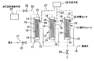
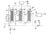
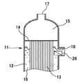
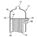
図1及び図2は、膜ユニットとして3基の内圧式膜モジュールを使用した膜ろ過装置に本発明を適用した形態例を示すもので、図1は膜モジュールの一次側(原水側)に加圧空気を供給し、膜モジュールの二次側(透過水側)に音響センサを設けた例を示す系統図、図2は膜モジュールの二次側(透過水側)に加圧空気を供給し、膜モジュールの一次側(原水側)に音響センサを設けた例を示す系統図である。 1 and 2 show an embodiment in which the present invention is applied to a membrane filtration device using three internal pressure membrane modules as membrane units. FIG. 1 shows the addition to the primary side (raw water side) of the membrane module. A system diagram showing an example in which compressed air is supplied and an acoustic sensor is provided on the secondary side (permeate side) of the membrane module. FIG. 2 is a diagram showing the case where pressurized air is supplied to the secondary side (permeate side) of the membrane module. It is a systematic diagram which shows the example which provided the acoustic sensor in the primary side (raw water side) of a membrane module.
図1及び図2にそれぞれ示す膜ろ過装置に用いられている膜モジュール11は、円筒状のケース12内を、中空糸膜13の両端をそれぞれ保持する一対の隔壁14によって両端の原水流入室15と隔壁14間の透過水流出室16とに区画するとともに、原水流入室15に原水流入管17を、透過水流出室16に透過水流出管18をそれぞれ接続したものである。原水は、原水流入管17から各膜モジュール11の原水流入室15に所定圧力で供給され、隔壁14を貫通して原水流入室15に連通した中空糸膜内部側に流入する。中空糸膜13で固液分離されて透過水流出室16に透過した水は、透過水流出管18を通って流出する。
A
図1に示すように、膜モジュール11の一次側に加圧空気を供給する場合は、膜モジュール11の一次側において、原水流入管17の上流側に遮断弁21を設け、該遮断弁21より下流側の原水流入管17に空気供給弁22を有する空気供給管23を介して加圧空気供給手段24を接続するとともに、一次側の原水を原水流入室15から排出するための排水弁25を設ける。また、膜モジュール11の二次側では、透過水流出室16に音響センサ26をそれぞれ設けるとともに、各音響センサ26をケーブル27によって判定手段28に接続する。
As shown in FIG. 1, when pressurized air is supplied to the primary side of the
図1に示す膜ろ過装置で膜破断の有無を判定するときには、まず、膜ろ過処理を中断して遮断弁21を閉じ、排水弁25及び空気供給弁22を開くとともに、加圧空気供給手段24を作動させて原水流入室15内に加圧空気を供給し、膜モジュール11の一次側から原水を排出する。中空糸膜13の内部側が確実に加圧空気で満たされた時点で排水弁25を閉じ、膜モジュール11の一次側の圧力を上昇させる。この状態で、中空糸膜13に破断が無ければ、使用している中空糸膜13のバブルポイント以下の空気圧力では中空糸膜13は空気を透過させないため、音響センサ26で集音した音には空気漏洩音は含まれていない。
When determining the presence or absence of membrane breakage in the membrane filtration apparatus shown in FIG. 1, first, the membrane filtration process is interrupted, the
一方、中空糸膜13に破断が発生している場合は、バブルポイント以下の空気圧力で中空糸膜13の破断部分から空気が透過水流出室16内の水中に漏洩するため、この空気漏洩音が音響センサ26に集音され、ケーブル27を介して判定手段28に伝達される。判定手段28では、空気漏洩音の有無、すなわち、膜破断の有無を判定する。判定の手法としては、音響センサ26からの信号をフーリエ変換して周波数毎の音の振幅を求め、あらかじめ設定した周波数における振幅を求めることにより、あるいは、あらかじめ設定した周波数範囲における振幅の積分値又は平均値を算出することにより、その大きさから漏洩音の有無を判定する方法を採用することができる。なお、判定手段28には、フーリエ変換機能、振幅算出機能、平均値や積分値の算出機能、判定機能、警報機能等を備えた各種演算装置を使用することができる。
On the other hand, when the
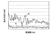
図3に、膜破断が無いときの音Aと、膜破断が発生したときの音Bとを測定した例を示す。膜破断が発生した場合には、広い周波数域で振幅に大きな差異が生じる。浄水設備においては、ポンプやインバータ等の騒音を発する機器が存在するが、これらの機器が発する騒音については、振幅の大きい周波数域は限られている。したがって、判定装置28において、前記機器による騒音の影響を受けない周波数域をあらかじめ設定し、この周波数又は周波数範囲で漏洩の判定を行うことにより、非常に高い精度で膜破断の検知を行うことが可能となる。また、各音響センサ26からの信号を判定手段28で別個に処理することにより、膜破断が発生した膜モジュール11を容易に特定することができる。
FIG. 3 shows an example in which the sound A when there is no film breakage and the sound B when a film breakage occurs are measured. When film breakage occurs, there is a large difference in amplitude over a wide frequency range. In water purification facilities, there are devices that emit noise, such as pumps and inverters, but for the noise emitted by these devices, the frequency range with a large amplitude is limited. Therefore, in the determination device 28, it is possible to detect a film break with very high accuracy by setting in advance a frequency range that is not affected by noise from the equipment and determining leakage at this frequency or frequency range. It becomes possible. Further, the signal from each
膜破断が発生していないときには、加圧空気供給手段24を止めて空気供給弁22を閉じるとともに、遮断弁21を開いて通常の膜ろ過処理に復帰する。また、膜破断が発生していることを検知したときには、膜ろ過装置の運転を停止して警報を発生させるようにする。これにより、膜破断が発生した膜モジュール11を速やかに交換することができ、透過水の水質が悪化することを防止できる。
When membrane breakage does not occur, the pressurized air supply means 24 is stopped and the
図2に示すように、膜モジュール11の二次側に加圧空気を供給する場合は、膜モジュール11の二次側において、透過水流出管18の下流側に遮断弁31を設け、該遮断弁31より上流側の透過水流出管18に空気供給弁32を有する空気供給管33を介して加圧空気供給手段34を接続するとともに、透過水を透過水流出室16から排出するための排水弁35を設ける。また、膜モジュール11の一次側では、原水流入室15に音響センサ36を設けるとともに、各音響センサ36をケーブル37によって判定手段38に接続する。
As shown in FIG. 2, when supplying pressurized air to the secondary side of the
なお、透過水流出室16から透過水を排出して透過水流出室16内を確実に加圧空気で満たすためには、透過水流出室16の最下部に排水弁を有する排水管を別途に設けることが望ましい。また、ケース12が軸線を水平方向に向けて設置されている場合には、透過水流出管18をケース下部側に接続すればよい。
In order to discharge the permeated water from the
図2に示す膜ろ過装置で膜破断の有無を判定するときには、まず、膜ろ過処理を中断して遮断弁31を閉じ、排水弁35及び空気供給弁32を開くとともに、加圧空気供給手段34を作動させて透過水流出室16内に加圧空気を供給し、膜モジュール11の二次側から透過水を排出する。中空糸膜13の外部側が確実に加圧空気で満たされた時点で排水弁35を閉じ、膜モジュール11の二次側の圧力を上昇させる。
When determining the presence or absence of membrane breakage in the membrane filtration apparatus shown in FIG. 2, first, the membrane filtration process is interrupted, the
この状態で、中空糸膜13に破断が無ければ、前記同様に、中空糸膜13のバブルポイント以下の空気圧力において音響センサ36で集音した音には空気漏洩音は含まれていないが、中空糸膜13に破断が発生している場合には、中空糸膜13の破断部分から空気が中空糸膜13内部側に漏洩して原水流入室15に向かって流れるため、この空気漏洩音が音響センサ36に集音されることにより、判定手段28で空気漏洩音の発生、すなわち、膜破断の発生が検知される。
In this state, if the
なお、図1及び図2では、膜破断の検知に必要な弁や機器、配管等を記載しており、通常の膜ろ過処理に必要な弁や計器類の図示は省略している。また、以下の説明において、図1に示した構成要素と同一の構成要素には、それぞれ同一符号を付して詳細な説明は省略する。 1 and 2 show valves, equipment, piping, and the like necessary for detecting membrane breakage, and illustration of valves and instruments necessary for normal membrane filtration processing is omitted. In the following description, the same components as those shown in FIG. 1 are denoted by the same reference numerals, and detailed description thereof is omitted.
音響センサ26,36は、水中使用が可能で、原水の供給圧力や加圧空気の圧力に耐えられるものならば、任意のものを選択することができる。また、音響センサ26,36の取付構造は、音響センサ26,36の大きさや形状、ケース12や接続される配管の構造や状態等に応じて適当な取付手段を用いることができる。また、ケース12の壁体にソケットを設けて音響センサを膜モジュールに直接取り付けることもでき、原水流入管17や透過水流出管18のケース近傍に取り付けることもできる。
The
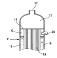
音響センサ26,36の取付位置も任意であるが、使用する音響センサが気中に露出したことを容易に検知できる場合で、膜モジュール11の一次側に加圧空気を供給する場合は、図4及び図5の要部断面図に示すように、音響センサ26を透過水流出室16の上部に設けることが好ましい。このとき、膜破断が僅かで透過水流出室16の水中に漏出する気泡の量が比較的少ない図4に示すような状態の場合には、前述のように空気漏洩音によって膜破断を検知でき、膜破断が大きくて気泡の漏れが顕著なときには、図5に示すように透過水流出室16の水位が低下し、音響センサ26が空気G中に露出するため、この音響センサ26の気中への露出によっても膜破断の発生を検知することができる。
The attachment positions of the
一方、音響センサが気中に露出することが望ましくない場合には、図6の要部断面図に示すように、透過水流出管18が接続した流出口よりも下方に音響センサ26を設置する構造が採用可能である。これにより、気泡の漏れが顕著になっても、透過水流出室16の上方に浮上した空気を透過水流出管18から排出できるので、音響センサ26が気中に露出することを防止できる。また、図7の要部断面図に示すように、透過水流出管18の口径が十分に大きい場合には、音響センサ26を透過水流出管18内(流出口内)に設置してもよい。
On the other hand, when it is not desirable that the acoustic sensor is exposed to the air, the
この場合、透過水流出管18は、立ち上げ部を設けるなどして、透過水流出管18内の水位が下がらないような設計とすることが望ましい。これにより、気泡の漏れが顕著で水位が低下した場合には、透過水流出管18を気泡が通過する音でも破断を検知することが可能となる。
In this case, it is desirable that the permeated
さらに、図8の要部断面図に示すように、透過水流出室16の上端部に、透過水流出管とは別の空気抜き管19を接続し、膜破断の有無を判定するときに、空気抜き管19に設けた排気弁(図示せず)を開いた状態とし、透過水流出管18を遮断した状態で行うことにより、透過水流出室16の上方に浮上した空気を空気抜き管19から外部に排出でき、音響センサ26が気中に露出することを防止できる。
Further, as shown in the cross-sectional view of the main part of FIG. 8, an
また、膜モジュール11の一次側に加圧空気を供給すると、空気の過飽和による現象で膜モジュール11の二次側に若干の空気が残ってしまうことがあり、二次側に残った空気が中空糸膜13の寿命に悪影響を及ぼす懸念がある。このような場合、前記空気抜き管19を設けて膜ろ過処理を再開した後に排気弁をしばらく開いておくことにより、空気抜き管19から透過水流出室16内の空気を確実に排出することができ、残存空気による中空糸膜13への悪影響を回避することができる。加えて、中空糸膜13を交換した後の試運転等の際にも、膜モジュール11の二次側から空気を簡単かつ確実に排出できるので、試運転等も容易に行うことができる。しかも、空気抜き管19は、原水流入管17や透過水流出管18に比べて小口径の管で形成できるので、空気抜き管19の設置コストは僅かで済む。
In addition, when pressurized air is supplied to the primary side of the
前述のように、内圧式膜モジュールにおける膜破断の検知は、加圧空気を膜モジュール11の一次側に供給しても、二次側に供給しても行うことができるが、膜モジュール11の一次側に加圧空気を供給することが好ましい。すなわち、加圧空気を二次側に供給したときには、破断部分から中空糸膜13の内部側に侵入した空気が中空糸膜内部側を通って原水流入室15に気泡となって漏出した音を検知するのに対し、加圧空気を一次側に供給すると、中空糸膜13の破断部分を空気が通過して透過水流出室16に漏出する音を直接検知することが可能となるので、気泡のみの音を検知するのに比べて検知性能を高めることが可能である。
As described above, the detection of membrane breakage in the internal pressure membrane module can be performed by supplying pressurized air to the primary side or the secondary side of the
さらに、膜モジュール11の一次側に加圧空気を供給すると、膜破断が発生していない場合に、透過水流出室16内に存在する透過水を加圧空気によって汚染してしまう可能性がなく、また、透過水流出管18側に設けられている水質測定計器類への加圧空気による影響も生じることがない。しかも、一次側に加圧空気を供給するように形成すれば、破断測定前に一次側の原水を排水弁25から排出するのと同時に一次側に溜まった汚れを原水と一緒に排出できるので、一次側の汚れを軽減することもできる。
Furthermore, when pressurized air is supplied to the primary side of the
なお、本形態例では、内圧式膜モジュールを使用した全量ろ過式の膜ろ過装置に本発明を適用した例を挙げて説明したが、他の形式、例えば外圧式の膜モジュールにも同様にして適用することが可能である。また、膜モジュールを構成するろ過膜は、前記中空糸膜に限るものではなく、各種ろ過膜を使用することができる。さらに、膜モジュールの二次側に加圧空気を供給するものでは、浸漬型の膜モジュールにも適用可能である。また、膜ろ過処理は、浄水設備に限らず、他の液体の膜ろ過にも適用できる。さらに、音響センサや膜モジュールの形式によっては、音響センサをケース外面に設け、ケース壁体を介して内部の空気漏洩音を検知することも可能である。 In this embodiment, the example in which the present invention is applied to a total-volume filtration type membrane filtration apparatus using an internal pressure type membrane module has been described. However, the same applies to other types, for example, an external pressure type membrane module. It is possible to apply. Moreover, the filtration membrane which comprises a membrane module is not restricted to the said hollow fiber membrane, Various filtration membranes can be used. Furthermore, in the case of supplying pressurized air to the secondary side of the membrane module, it can be applied to an immersion type membrane module. The membrane filtration process is not limited to water purification equipment but can be applied to membrane filtration of other liquids. Further, depending on the type of the acoustic sensor or the membrane module, it is possible to provide an acoustic sensor on the outer surface of the case and detect the air leakage sound inside through the case wall.
11…膜モジュール、12…ケース、13…中空糸膜、14…隔壁、15…原水流入室、16…透過水流出室、17…原水流入管、18…透過水流出管、19…空気抜き管、21,31…遮断弁、22,32…空気供給弁、23,33…空気供給管、24,34…加圧空気供給手段、25,35…排水弁、26,36…音響センサ、27,37…ケーブル、28、38…判定手段
DESCRIPTION OF
Claims (10)
Priority Applications (1)
| Application Number | Priority Date | Filing Date | Title |
|---|---|---|---|
| JP2004121356A JP2005296908A (en) | 2004-04-16 | 2004-04-16 | Membrane filtration device and membrane breakage detection method |
Applications Claiming Priority (1)
| Application Number | Priority Date | Filing Date | Title |
|---|---|---|---|
| JP2004121356A JP2005296908A (en) | 2004-04-16 | 2004-04-16 | Membrane filtration device and membrane breakage detection method |
Publications (1)
| Publication Number | Publication Date |
|---|---|
| JP2005296908A true JP2005296908A (en) | 2005-10-27 |
Family
ID=35329098
Family Applications (1)
| Application Number | Title | Priority Date | Filing Date |
|---|---|---|---|
| JP2004121356A Pending JP2005296908A (en) | 2004-04-16 | 2004-04-16 | Membrane filtration device and membrane breakage detection method |
Country Status (1)
| Country | Link |
|---|---|
| JP (1) | JP2005296908A (en) |
Cited By (7)
| Publication number | Priority date | Publication date | Assignee | Title |
|---|---|---|---|---|
| KR100950218B1 (en) * | 2009-09-09 | 2010-03-29 | 주식회사 한미엔텍 | Breakage sensing apparatus of hollow-fiber membrane module |
| JP2013039569A (en) * | 2012-10-05 | 2013-02-28 | Mitsui Eng & Shipbuild Co Ltd | Exchange method for film cartridge used for film processing equipment for ballast water processing |
| WO2015199434A1 (en) * | 2014-06-26 | 2015-12-30 | 고려대학교 산학협력단 | Device and method for determining integrity of separation membrane module using acoustic sensors |
| WO2017135235A1 (en) * | 2016-02-01 | 2017-08-10 | 三菱ケミカル株式会社 | Separation membrane diagnosis method, water processing method, separation membrane diagnosis device, water processing device and separation membrane diagnosis program |
| JP2020093207A (en) * | 2018-12-12 | 2020-06-18 | 株式会社クボタ | Film defect inspection method and film defect inspection device |
| JP2022165683A (en) * | 2021-04-20 | 2022-11-01 | 株式会社クラレ | Operation management method of hollow fiber membrane filtration device |
| JP2022187689A (en) * | 2021-06-08 | 2022-12-20 | Jfeスチール株式会社 | Metal body break detection device and metal body break detection method |
-
2004
- 2004-04-16 JP JP2004121356A patent/JP2005296908A/en active Pending
Cited By (13)
| Publication number | Priority date | Publication date | Assignee | Title |
|---|---|---|---|---|
| KR100950218B1 (en) * | 2009-09-09 | 2010-03-29 | 주식회사 한미엔텍 | Breakage sensing apparatus of hollow-fiber membrane module |
| JP2013039569A (en) * | 2012-10-05 | 2013-02-28 | Mitsui Eng & Shipbuild Co Ltd | Exchange method for film cartridge used for film processing equipment for ballast water processing |
| WO2015199434A1 (en) * | 2014-06-26 | 2015-12-30 | 고려대학교 산학협력단 | Device and method for determining integrity of separation membrane module using acoustic sensors |
| WO2017135235A1 (en) * | 2016-02-01 | 2017-08-10 | 三菱ケミカル株式会社 | Separation membrane diagnosis method, water processing method, separation membrane diagnosis device, water processing device and separation membrane diagnosis program |
| JPWO2017135235A1 (en) * | 2016-02-01 | 2018-02-08 | 三菱ケミカル株式会社 | Separation membrane diagnosis method, water treatment method, separation membrane diagnosis device, water treatment device, and separation membrane diagnosis program |
| WO2020121880A1 (en) * | 2018-12-12 | 2020-06-18 | 株式会社クボタ | Membrane defect inspection method and membrane defect inspection device |
| JP2020093207A (en) * | 2018-12-12 | 2020-06-18 | 株式会社クボタ | Film defect inspection method and film defect inspection device |
| US20220023802A1 (en) * | 2018-12-12 | 2022-01-27 | Kubota Corporation | Membrane defect inspection method and membrane defect inspection device |
| US11986773B2 (en) | 2018-12-12 | 2024-05-21 | Kubota Corporation | Membrane defect inspection method and membrane defect inspection device |
| JP2022165683A (en) * | 2021-04-20 | 2022-11-01 | 株式会社クラレ | Operation management method of hollow fiber membrane filtration device |
| JP7661100B2 (en) | 2021-04-20 | 2025-04-14 | 株式会社クラレ | Method for operating and managing hollow fiber membrane filtration equipment |
| JP2022187689A (en) * | 2021-06-08 | 2022-12-20 | Jfeスチール株式会社 | Metal body break detection device and metal body break detection method |
| JP7484821B2 (en) | 2021-06-08 | 2024-05-16 | Jfeスチール株式会社 | Metal body breakage detection device and metal body breakage detection method |
Similar Documents
| Publication | Publication Date | Title |
|---|---|---|
| JP3111101B2 (en) | Leak inspection method for membrane separation equipment | |
| EP1194217B1 (en) | Method and apparatus for testing the integrity of filtering membranes | |
| RU2113706C1 (en) | Method checking integrity of filtration element and filtration unit | |
| JP2001190938A (en) | Method of detecting breakage of water treating membrane | |
| US20110138936A1 (en) | Means for testing filter integrity in a liquid purification system | |
| JP2005296908A (en) | Membrane filtration device and membrane breakage detection method | |
| CN114235657B (en) | Method for testing the integrity of a filter medium | |
| JP2001269551A (en) | Method of detecting breakage of permeable membrane module of water purification system | |
| JP2007240373A (en) | Membrane damage detection device and membrane damage detection method for filtration system for water treatment | |
| CN113164877A (en) | Film defect inspection method and film defect inspection apparatus | |
| JP2007296516A (en) | Leak detection method and apparatus for membrane filtration system | |
| JP2025100759A (en) | Transmembrane pressure prediction method and water treatment device | |
| WO2019229872A1 (en) | Leak detection device and leak detection method | |
| US11986773B2 (en) | Membrane defect inspection method and membrane defect inspection device | |
| JPH0985011A (en) | Liquid leakage detector for deaeration module | |
| KR101753453B1 (en) | Hollow fiber membrane and method of detecting damage of membrane thereof | |
| JP2004237281A (en) | Membrane separation apparatus, and state detecction method for the apparatus | |
| JP2008253888A (en) | Membrane damage detection method | |
| JP7661100B2 (en) | Method for operating and managing hollow fiber membrane filtration equipment | |
| JP4461288B2 (en) | Filtration membrane abnormality detection method and apparatus | |
| JPH0975690A (en) | Water treatment filter damage detection method and apparatus, and water treatment apparatus including the apparatus | |
| JP3664083B2 (en) | Leak test method for hollow fiber membrane module | |
| JP2004188252A (en) | Membrane filtration apparatus and its operating method | |
| JP5500764B2 (en) | Fracture membrane module detector for filtration equipment | |
| JP4205984B2 (en) | Membrane filtration device and operation method thereof |
Legal Events
| Date | Code | Title | Description |
|---|---|---|---|
| A621 | Written request for application examination |
Effective date: 20070221 Free format text: JAPANESE INTERMEDIATE CODE: A621 |
|
| A977 | Report on retrieval |
Free format text: JAPANESE INTERMEDIATE CODE: A971007 Effective date: 20090305 |
|
| A131 | Notification of reasons for refusal |
Free format text: JAPANESE INTERMEDIATE CODE: A131 Effective date: 20090324 |
|
| A02 | Decision of refusal |
Free format text: JAPANESE INTERMEDIATE CODE: A02 Effective date: 20090721 |