JP2005296873A - Solid-gas mixing ejector and jet mill - Google Patents
Solid-gas mixing ejector and jet mill Download PDFInfo
- Publication number
- JP2005296873A JP2005296873A JP2004119504A JP2004119504A JP2005296873A JP 2005296873 A JP2005296873 A JP 2005296873A JP 2004119504 A JP2004119504 A JP 2004119504A JP 2004119504 A JP2004119504 A JP 2004119504A JP 2005296873 A JP2005296873 A JP 2005296873A
- Authority
- JP
- Japan
- Prior art keywords
- diameter
- flow path
- side section
- solid
- gas
- Prior art date
- Legal status (The legal status is an assumption and is not a legal conclusion. Google has not performed a legal analysis and makes no representation as to the accuracy of the status listed.)
- Granted
Links
- 239000000463 material Substances 0.000 claims description 18
- 238000010298 pulverizing process Methods 0.000 claims description 13
- 238000002347 injection Methods 0.000 claims description 11
- 239000007924 injection Substances 0.000 claims description 11
- 238000011144 upstream manufacturing Methods 0.000 claims description 8
- 239000000126 substance Substances 0.000 claims description 6
- 238000000227 grinding Methods 0.000 claims description 4
- 239000007787 solid Substances 0.000 claims description 2
- 239000000843 powder Substances 0.000 abstract description 14
- 239000012530 fluid Substances 0.000 abstract description 5
- 230000001133 acceleration Effects 0.000 description 8
- 239000000203 mixture Substances 0.000 description 3
- 238000005507 spraying Methods 0.000 description 2
- 238000007796 conventional method Methods 0.000 description 1
- 239000002245 particle Substances 0.000 description 1
- 230000002093 peripheral effect Effects 0.000 description 1
- 239000012254 powdered material Substances 0.000 description 1
- 239000008247 solid mixture Substances 0.000 description 1
Images


Landscapes
- Disintegrating Or Milling (AREA)
- Nozzles (AREA)
Abstract
Description
本発明は、粉状体を高圧気体と共に高速噴射させるのに使用する固気混合エジェクタとこのエジェクタを用いたジェットミルに関する。 The present invention relates to a solid-gas mixing ejector used for jetting a powdery body together with a high-pressure gas at high speed, and a jet mill using the ejector.
固気混合エジェクタは、駆動ノズルから噴射された高圧作動気体に粉状体を巻き込ませて高速噴射させるのに使用される。たとえば特許文献1に記載のジェットミルにおいて、高速ガス(気体)旋回流が形成されている破砕室内に砕料である粉状体を高圧ガスと共に噴射供給するのに使用されている。その他、粉体と気体を混合状態で高速噴射する場面で使用されることが多い。
The solid-gas mixing ejector is used to cause a high-pressure working gas ejected from a drive nozzle to pulverize a powdery body and eject it at high speed. For example, in the jet mill described in
この固気混合エジェクタは、流路途中に狭窄部を有する不等径導流管を用いて構成される。この不等径導流管は、高圧作動気体を噴射する駆動ノズルの噴射口前方で吸入口が開口するとともに、この吸入口に導入された高圧作動気体を流路の狭窄と拡開による流速変化を生じさせながら排出口へ導くように形成され、上記吸入口の上流側に導入された粉状体を上記作動気体とともに上記不等径導流管に導いて上記排出口から高速噴射させる。 This solid-gas mixing ejector is configured using an unequal-diameter conduit having a constricted portion in the middle of a flow path. This unequal-diameter guide pipe has an inlet opening in front of the injection nozzle of a drive nozzle that injects high-pressure working gas, and the flow rate change caused by narrowing and widening the flow path of the high-pressure working gas introduced into this inlet The powdery substance introduced to the upstream side of the suction port is guided to the unequal-diameter guide pipe together with the working gas, and is ejected from the discharge port at a high speed.
図5は、特許文献1などに開示されている従来の固気混合エジェクタの構成例を示す。同図において、(a)は固気混合エジェクタ10’と駆動ノズル20の組み合せ状態、(b)はそのエジェクタ10’の要部をなす不等径導流管11’をそれぞれ断面図で示す。
FIG. 5 shows a configuration example of a conventional solid-gas mixed ejector disclosed in
同図に示すように、従来の固気混合エジェクタは、吸入口12から排出口13までの間に吸気側、中間、排気側の3つの導流セクションZ1,Z2,Z3が順次設けられた不等径導流管11’を用いて構成されている。
As shown in the figure, the conventional solid-gas mixing ejector has three intake sections Z1, Z2, and Z3 on the intake side, the intermediate side, and the exhaust side between the
吸気側セクションZ1(特許文献1の負圧発生部に相当)は、上流側の吸入口12に向けて流路径が漸次拡大する拡開形状(ホーン状)が形成されている。この吸気側セクションZ1では、駆動ノズル20から噴射されて吸入口に導入された高速作動気体(ガス)が口径D1からD2までの流路狭窄により加速される。この加速流により発生する負圧により、吸入口12側に導入された粉状体を上記作動気体に巻き込んでエジェクタ10’内に導流させることができる。つまり、吸気側セクションZ1は粉状体を吸入する負圧発生部を形成する。
The intake side section Z1 (corresponding to the negative pressure generating portion of Patent Document 1) is formed with an expanded shape (horn shape) in which the flow path diameter gradually increases toward the
上記吸気側セクションZ1の下流端すなわち流路狭窄端には中間セクションZ2(特許文献1のスロート部に相当)が連接している。この中間セクションZ2は、上記吸気側セクションZ1の最小流路径D2が所定長さ(h)にわたって続く等径流路部によって形成されている。吸気側セクションZ1に導流された作動気体と粉状体は、この中間セクションZ2を通過する間に混合促進される。 An intermediate section Z2 (corresponding to the throat portion of Patent Document 1) is connected to the downstream end of the intake side section Z1, that is, the flow path constriction end. The intermediate section Z2 is formed by an equal-diameter channel portion in which the minimum channel diameter D2 of the intake side section Z1 continues for a predetermined length (h). The working gas and the powdery substance introduced into the intake side section Z1 are mixed and promoted while passing through the intermediate section Z2.
上記中間セクションZ2の下流端には排気側セクションZ3が連接している。この排気側セクションZ3は、下流側の排出口13に向けて流路径が漸次拡大する拡開形状(ホーン状)に形成されている。中間セクションZ2にて混合促進された固気混合体は、この排気側セクションZ3で減圧されながら排出口へ導かれて噴射放出される。 An exhaust side section Z3 is connected to the downstream end of the intermediate section Z2. The exhaust side section Z3 is formed in an expanded shape (horn shape) in which the flow path diameter gradually increases toward the downstream discharge port 13. The solid-gas mixture whose mixing has been promoted in the intermediate section Z2 is guided to the discharge port while being decompressed in the exhaust side section Z3, and is ejected and discharged.
上述した従来の技術では、吸気側セクションZ1の下流端に、その吸気側セクションZ1の最小流路径D2が等径で連続する中間セクションZ2が介在させられている。この中間セクションZ2は作動気体と粉状体の混合促進に寄与するとされている。したがって、良好な固気混合状態を得ることを目的とするならば、その中間セクションZ2の介在は有効かも知れない。 In the conventional technique described above, an intermediate section Z2 in which the minimum flow path diameter D2 of the intake side section Z1 is continuous with an equal diameter is interposed at the downstream end of the intake side section Z1. This intermediate section Z2 is supposed to contribute to the promotion of mixing of the working gas and the powder. Therefore, if the objective is to obtain a good solid-gas mixing state, the intervention of the intermediate section Z2 may be effective.
しかし、たとえばジェットミルのように、砕料である粉状体を粉砕室内にできるだけ高速で噴射させることに着目した場合、上記中間セクションZ2は、狭窄された最小流路径D2が連続することにより、粉状体の搬送キャリアである作動流体(作動気体)を減速させる流路抵抗を増大させ、その作動流体によって搬送される粉状体の噴射速度を低下させる原因になることが判明した。 However, when paying attention to spraying the powdery material as a pulverizer into the pulverization chamber as fast as possible, such as a jet mill, the intermediate section Z2 has a continuous narrowed minimum flow path diameter D2, It has been found that the flow resistance for decelerating the working fluid (working gas), which is a carrier for transporting the powdery body, is increased, which causes a decrease in the injection speed of the powdery body transported by the working fluid.
つまり、上述した従来の固気混合エジェクタ10’は、固気の混合状態を高めることを主目的とする用途には適しているが、作動気体により搬送される粉状体の噴射速度を高めることを主目的とする用途では、その作動気体の運動エネルギーが上記粉状体の加速に効率良く利用されない、という問題のあることが判明した。
That is, the above-described conventional solid-
本発明は以上のような技術背景を鑑みたものであって、その目的は、駆動ノズルから噴射される高圧作動気体に粉状体を巻き込んで高速噴射させる固気混合エジェクタにおいて、上記作動流体の運動エネルギーを上記粉状体の加速駆動に効率良く利用し、これによりその粉状体を高速で噴射させることができるようにした固気混合エジェクタを提供することにある。また、本発明は、砕料である粉状体の噴射速度を高めることにより破砕効率を向上させたジェットミルを提供することも目的とする。 The present invention has been made in view of the technical background as described above, and an object of the present invention is to provide a solid-gas mixing ejector in which a powdery body is entrained in a high-pressure working gas ejected from a drive nozzle and ejected at a high speed. An object of the present invention is to provide a solid-gas mixing ejector that efficiently uses kinetic energy for the acceleration drive of the powdery body, thereby enabling the powdery body to be ejected at a high speed. Another object of the present invention is to provide a jet mill in which the crushing efficiency is improved by increasing the injection speed of the powdery material that is a pulverizer.
本発明は固気混合エジェクタにおける解決手段として、次の(1)の手段を提供する。
(1)高圧作動気体を噴射する駆動ノズルの噴射口前方で吸入口が開口するとともに、この吸入口に導入された高圧作動気体を流路の狭窄と拡開による流速変化を生じさせながら排出口へ導いて噴射放出させる不等径導流管を有し、上記吸入口の上流側に導入された粉状体を上記作動気体とともに上記不等径導流管に導いて上記排出口から高速噴射させるようにした固気混合エジェクタにおいて、
上記不等径導流管は、上流の吸入口に向けて流路径が漸次拡大する吸気側セクションと、この吸気側セクションの下流端に連接するとともに、その下流端から排出口に向けて流路径が漸次拡大する排気側セクションとが同軸状に形成され、
吸気側セクションと排気側セクションはそれぞれ、両セクションが接する境界から吸入口および排出口までの全長にわたって流路径が漸次増大する拡開形状をなすとともに、全流路長に対する排気側セクションの流路長の割合が80%以上であることを特徴とする固気混合エジェクタ。
The present invention provides the following means (1) as a solving means in the solid-gas mixing ejector.
(1) A suction port is opened in front of an ejection port of a drive nozzle that ejects high-pressure working gas, and the high-pressure working gas introduced into the suction port is discharged while causing flow rate changes due to narrowing and widening of the flow path. A non-equal-diameter conduit that is guided to and discharged by discharge to the unequal-diameter conduit along with the working gas. In the solid-gas mixing ejector
The non-equal-diameter guide pipe is connected to the intake side section where the flow path diameter gradually increases toward the upstream suction port, and to the downstream end of the intake side section, and the flow path diameter from the downstream end toward the discharge port. Is formed coaxially with the exhaust side section that gradually expands,
Each of the intake side section and the exhaust side section has an expanded shape in which the flow path diameter gradually increases over the entire length from the boundary where both sections contact to the intake port and the exhaust port, and the flow length of the exhaust side section relative to the total flow path length. The solid-gas mixing ejector characterized by the fact that the ratio is 80% or more.
上記手段(1)においては、さらに次のような手段を備えることが好適または望ましい。
(2)上記(1)の手段において、前記吸気側セクションの流路長が前記吸入口の口径と同寸または少なくともその口径の0.8倍以上2倍未満であることを特徴とする固気混合エジェクタ。
It is preferable or desirable that the above means (1) further includes the following means.
(2) In the means of (1), the flow path length of the suction side section is the same as the diameter of the suction port or at least 0.8 times or more and less than twice the diameter of the suction port. Mixed ejector.
(3)上記(1)または(2)の手段において、前記吸入口径が前記境界での流路径の1.5倍以上3倍以下であることを特徴とする固気混合エジェクタ。 (3) The solid-gas mixing ejector according to (1) or (2), wherein the suction port diameter is 1.5 to 3 times the flow path diameter at the boundary.
(4)上記(1)〜(3)のいずれかの手段において、前記吸気側セクションの流路径が、流路軸に直交して前記境界を通る線上に中心を置く円弧に沿って変化していることを特徴とする固気混合エジェクタ。 (4) In any one of the above-mentioned means (1) to (3), the flow path diameter of the intake side section changes along an arc centered on a line passing through the boundary perpendicular to the flow path axis. Solid-gas mixing ejector characterized by
(5)上記(1)〜(4)のいずれかの手段において、前記排気側セクションの流路径が、流路軸に直交して前記境界を通る線上に中心を置く円弧に沿って変化していることを特徴とする固気混合エジェクタ。 (5) In any one of the above means (1) to (4), the flow path diameter of the exhaust side section changes along an arc centered on a line passing through the boundary perpendicular to the flow path axis. Solid-gas mixing ejector characterized by
(6)上記(1)〜(5)のいずれかの手段において、前記排気側セクションの流路径と前記吸気側セクションの流路径が、それぞれ流路軸に直交して前記境界を通る線上に中心を置く円弧に沿って変化するとともに、排気側セクションの流路径変化を規定する円弧の曲率半径が、吸気側セクションの流路径変化を規定する円弧の曲率半径の25〜50倍に設定されていることを特徴とする固気混合エジェクタ。 (6) In any one of the above means (1) to (5), the flow path diameter of the exhaust side section and the flow path diameter of the intake side section are each centered on a line passing through the boundary perpendicular to the flow path axis. The radius of curvature of the arc that defines the flow path diameter change of the exhaust side section is set to 25 to 50 times the radius of curvature of the arc that defines the flow path diameter change of the intake side section. Solid-gas mixing ejector characterized by that.
(7)上記(1)〜(6)のいずれかの手段において、前記吸入口の断面と、前記排出口の軸線と直交する断面とが略同径であることを特徴とする固気混合エジェクタ。 (7) In any one of the above means (1) to (6), the cross section of the suction port and the cross section perpendicular to the axis of the discharge port have substantially the same diameter, .
(8)上記(1)〜(7)のいずれかの手段において、前記吸入口が前記不等径導流管の外径まで拡開されていることを特徴とする固気混合エジェクタ。 (8) The solid-gas mixing ejector according to any one of the above (1) to (7), wherein the suction port is expanded to the outer diameter of the unequal-diameter guide pipe.
また、本発明は、ジェットミルにおける解決手段するとして、次の(9)の手段を提供する
(9)上記(1)〜(9)のいずれかの手段において、円形または環状の粉砕室内に高圧気体を噴射して高速気体旋回流を形成させるとともに、その粉砕室内に砕料である粉状体を高圧気体と共に噴射供給することにより細粒化破砕を行わせるジェットミルにおいて、上記(1)〜(8)のいずれかに記載の固気混合エジェクタを用いて上記粉状体を上記粉砕室内に噴射供給させるようにしたことを特徴とするジェットミル。
Further, the present invention provides the following means (9) as means for solving the problem in the jet mill: (9) In any one of the above means (1) to (9), a high pressure is introduced into the circular or annular grinding chamber. In the jet mill in which gas is injected to form a high-speed gas swirl flow and finely pulverized and crushed by injecting and supplying a powdery material as a pulverizer together with high-pressure gas into the pulverization chamber, (8) A jet mill characterized in that the powdery body is jetted and supplied into the grinding chamber using the solid-gas mixing ejector according to any one of (8).
駆動ノズルから噴射される高圧作動気体に粉状体を巻き込んで高速噴射させる固気混合エジェクタにおいて、上記作動流体の運動エネルギーを上記粉状体の加速駆動に効率良く利用し、これによりその粉状体を高速で噴射させることができるようにした固気混合エジェクタを提供することができる。また、砕料である粉状体の噴射速度を高めることにより破砕効率を向上させたジェットミルを提供することができる。 In a solid-gas mixing ejector in which a powdery body is entrained in a high-pressure working gas ejected from a drive nozzle and jetted at high speed, the kinetic energy of the working fluid is efficiently used for acceleration driving of the powdery body, thereby It is possible to provide a solid-gas mixing ejector that can jet a body at high speed. Moreover, the jet mill which improved the crushing efficiency can be provided by raising the injection speed of the powdery body which is a crushing material.
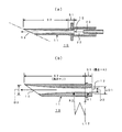
図1は本発明による固気混合エジェクタの一実施形態を示す。同図において、(a)は固気混合エジェクタ10と駆動ノズル20の組み合せ状態、(b)はそのエジェクタ10の要部をなす不等径導流管11をそれぞれ断面図で示す。
FIG. 1 shows an embodiment of a solid-gas mixing ejector according to the present invention. In the same figure, (a) is a combined state of the solid-
同図に示す固気混合エジェクタ10は固体である粉状体を作動期待とともに高速噴射させるものであって、吸入口12と排出口13の間に流路狭窄部を有する不等径導流管11を用いて構成されている。この不等径導流管11は、円形断面の流路が同軸方向に直線貫通するとともに、その軸線を中心に狭窄および拡開する不等径流路を形成する。
A solid-
上記不等径導流管11は、(a)に示すように、高圧作動気体を噴射する駆動ノズル20の噴射口前方にて吸入口12が開口するように設置されている。駆動ノズル20と不等径導流管11は一直線上に配置されている。駆動ノズル20の噴射口と不等径導流管11の間すなわち上記吸入口12の上流側には、粉状体の供給空間部22が形成されている。
The unequal-diameter guide pipe 11 is installed so that the
駆動ノズル20から吸入口12に導入された高圧作動気体は、流路の狭窄と拡開による流速変化を生じながら排出口13へ導流されて噴射放出される。これにともない、上記吸入口12の上流側に導入された粉状体は、上記作動気体とともに上記不等径導流管11に導かれて上記排出口13から高速噴射されるようになっている。
The high-pressure working gas introduced from the
上記不等径導流管11には、(b)に示すように、上流の吸入口12に向けて流路径が漸次拡大する吸気側セクションS1と、この吸気側セクションS1の下流端に連接するとともに、その下流端から排出口13に向けて流路径が漸次拡大する排気側セクションS2とが同軸状に形成されている。図示の実施形態では排出口13が斜めに開いているが、軸線に直交する断面では吸入口12と略等径(D1≒D3)に形成されている。
The unequal-diameter guide pipe 11 is connected to an intake side section S1 whose flow path diameter gradually increases toward the
吸気側セクションS1と排気側セクションS2はそれぞれ、両セクションS1,S2が接する境界から吸入口12および排出口13までの全長にわたって流路径が漸次増大する拡開形状をなすとともに、吸気側セクションS1の流路長(h)に対して排気側セクションS2の流路長jが十分に長くなるように構成されている。具体的には、全流路長(h+j)に対する排気側セクションS2の流路長(j)の割合が80%以上(j/(h+j)≧0.8)となるように構成されている。
Each of the intake side section S1 and the exhaust side section S2 has an expanded shape in which the flow path diameter gradually increases over the entire length from the boundary where both sections S1 and S2 are in contact to the
さらに、図示の実施形態では、吸気側セクションS1の流路長(h)が上記吸入口の口径D1と略同寸に形成されている。上記吸入口径D1は上記境界での流路径(D2)の約2倍に形成されている。 Further, in the illustrated embodiment, the flow path length (h) of the intake side section S1 is formed to be approximately the same size as the diameter D1 of the intake port. The suction port diameter D1 is formed to be about twice the flow path diameter (D2) at the boundary.
吸気側セクションS1の流路径は、流路軸に直交して上記境界を通る線L12上に中心を置く円弧に沿って変化するように形成されている。また、排気側セクションS2の流路径は、上記流路軸に直交して上記境界を通る線L12上に中心を置く円弧に沿って変化するように形成されている。 The flow path diameter of the intake side section S1 is formed so as to change along an arc centered on a line L12 passing through the boundary perpendicular to the flow path axis. Further, the flow path diameter of the exhaust side section S2 is formed so as to change along an arc centered on a line L12 passing through the boundary perpendicular to the flow path axis.
つまり、吸気側セクションS1の流路径と排気側セクションS2の流路径は共に流路軸に直交して上記境界を通る線L12上に中心を置く円弧に沿って変化するように形成され、これにより、前者は上記吸入口12から上記境界に向かって狭窄する流路を形成し、後者は上記境界から上記排出口13へ向かって漸次拡開するホーン状の流路を形成する。
That is, both the flow path diameter of the intake side section S1 and the flow path diameter of the exhaust side section S2 are formed so as to change along an arc centered on a line L12 passing through the boundary perpendicular to the flow path axis. The former forms a flow path that narrows from the
排気側セクションS2の流路径変化を規定する円弧の曲率半径R2は、ホーン状の拡開形状が実効的に形成される範囲において、吸気側セクションS1の流路径変化を規定する円弧の曲率半径R1よりも十分に大きく設定されている。具体的は、R2/R1=25〜50倍の範囲が適当である。また、上記吸入口12と上記排出口13は略同径に形成されている。
The radius of curvature R2 of the arc that defines the flow path diameter change of the exhaust side section S2 is within the range in which the horn-shaped expanded shape is effectively formed, and the radius of curvature R1 of the arc that defines the flow path diameter change of the intake side section S1. It is set sufficiently larger than. Specifically, a range of R2 / R1 = 25 to 50 times is appropriate. The
上述した実施形態の固気混合エジェクタ10では、まず、駆動ノズル20から噴射された高速作動気体(ガス)が吸気側セクションS1の流路狭窄により加速されるが、この加速流により発生する負圧により、吸入口12側に導入された粉状体が上記作動気体に巻き込まれる形で不等径導流管11内を導流させられる、そして、吸気側セクションS1の流路狭窄部を作動気体とともに加速されながら通過する。
In the solid-
吸気側セクションS1にて加速された固気混合気体は、この吸気側セクションS1の下流端に連接する排気側セクションS2に導流され、ここで漸次減圧されながら排出口へ導かれて噴射放出される。 The gas-solid mixture gas accelerated in the intake side section S1 is guided to the exhaust side section S2 connected to the downstream end of the intake side section S1, where it is guided to the discharge port while being gradually reduced in pressure and discharged. The
ここで注目すべきは、吸気側セクションS1の流路狭窄部にて加速された作動気体と粉状体の混合体は、縮径流路が連続する中間セクションを通過することなく、排気側セクションS2へ導かれて噴射放出されることであり、これにより、混合気体の運動エネルギーを減じる流路抵抗を大幅に少なくして粉状体の高速噴射を可能にすることができる。 It should be noted here that the mixture of the working gas and the powdery material accelerated in the flow path constriction portion of the intake side section S1 does not pass through the intermediate section where the diameter-reduced flow path is continuous, and does not pass through the exhaust side section S2. In this way, the flow resistance that reduces the kinetic energy of the mixed gas can be greatly reduced, and the powdery body can be jetted at high speed.
この場合、中間セクション(スロート部)が介在しないことにより、作動気体と粉状体の混合率低下が懸念されるが、中間セクションの長さ部分を排気側セクションS2の長さに置き換えたことにより、つまり排気側セクションS2の長さ(j)を中間セクションの分だけ長くしたことにより、その排気側セクションS2において固気混合が相当程度に促進されることが判明した。 In this case, since the intermediate section (throat portion) is not interposed, there is a concern that the mixing ratio of the working gas and the powder is reduced. However, by replacing the length of the intermediate section with the length of the exhaust side section S2. That is, it has been found that by increasing the length (j) of the exhaust side section S2 by an amount corresponding to the intermediate section, solid-gas mixing is considerably promoted in the exhaust side section S2.
上述したように、本発明に係る固気混合エジェクタ10では、中間セクションを介在させず、吸気側セクションS1と排気側セクションS2だけの2セクション構成とすることにより、駆動ノズル20から噴射される高圧作動気体の運動エネルギーを粉状体の加速駆動に効率良く作用させることができ、これによりその粉状体を高速で噴射させることができる。
As described above, the solid-
本発明に係る固気混合エジェクタ10では、吸気側セクションS1の流路長hが吸入口の口径D1と同寸または少なくともその口径D1の0.8倍以上2倍未満であることが好ましい。0.8倍未満では作動気体と吸入口12内壁面間に作用する抵抗が増大し、2倍以上では粉状体を作動気体に巻き込んで加速する際の効率が低下する。
In the solid-
また、吸入口径D1と上記境界での流路径の比(D1/D2)は、1.5倍以上3倍以下であることが好ましい。1.5倍未満では流路狭窄が不充分なことにより負圧発生効率が低下する一方、3倍を超えると狭窄部での流路が狭くなり過ぎて流路抵抗が増大がする。 In addition, the ratio (D1 / D2) of the suction port diameter D1 and the flow path diameter at the boundary is preferably 1.5 times or more and 3 times or less. If the ratio is less than 1.5 times, the efficiency of generating negative pressure is reduced due to insufficient channel constriction. On the other hand, if the ratio exceeds three times, the channel at the constriction becomes too narrow and the channel resistance increases.
吸気側セクションS1の流路径は、前述したように、流路軸に直交して上記境界を通る線L12上に中心を置く円弧に沿って変化させているが、これにより、流路狭窄による作動気体の加速を円滑にすることができる。同様に、排気側セクションS2の流路径も、前述したように、流路軸に直交して上記境界を通る線L12上に中心を置く円弧に沿って変化させているが、これは、吸気側S1セクションにて加速された固気混合体をその運動エネルギーを保ちつつ緩やかに減圧して高速噴射させるのに有効である。 As described above, the flow path diameter of the intake-side section S1 is changed along an arc centered on the line L12 passing through the boundary perpendicular to the flow path axis. The acceleration of the gas can be made smooth. Similarly, as described above, the flow path diameter of the exhaust side section S2 is also changed along an arc centered on the line L12 passing through the boundary perpendicular to the flow path axis. This is effective for causing the solid-gas mixture accelerated in the S1 section to be gradually decompressed and sprayed at high speed while maintaining its kinetic energy.
同様の理由により、排気側セクションS2の流路径変化を規定する円弧の曲率半径R2は、吸気側セクションS1の流路径変化を規定する円弧の曲率半径R1の25〜50倍の範囲が好適である。 For the same reason, the radius of curvature R2 of the arc that defines the change in flow path diameter of the exhaust side section S2 is preferably in the range of 25 to 50 times the radius of curvature R1 of the arc that defines the change of flow path diameter of the intake side section S1. .
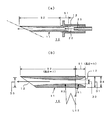
図2は、本発明による固気混合エジェクタの別の実施形態を示す。同図において、(a)は固気混合エジェクタ10と駆動ノズル20の組み合せ状態、(b)はそのエジェクタ10の要部をなす不等径導流管11をそれぞれ断面図で示す。
図1に示した実施形態との相違点に着目すると、図2に示す実施例体では、吸気口12の開口が導流管11の外径D4まで拡開している(D1≒D4)。つまり、導流管11の縁端面がエッジ状になっているが、これにより、粉状体の吸入効率を高めることができる。
FIG. 2 shows another embodiment of the solid-gas mixing ejector according to the present invention. In the same figure, (a) is a combined state of the solid-
Focusing on the difference from the embodiment shown in FIG. 1, in the example body shown in FIG. 2, the opening of the
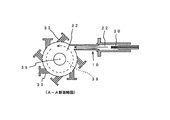
図3は、本発明による固気混合エジェクタを用いたジェットミル30の要部断面を示す。図4は、図3のA−A部分断面を省略して示す。なお、図1,2と共通する部分については共通符号で示す。
FIG. 3 shows a cross-sectional view of a main part of a
図3および図4に示すジェットミル30は、円形または環状の粉砕室32内に高圧ガスを噴射して高速ガス旋回流を形成させるとともに、その粉砕室32内に砕料である粉状体を高圧ガスと共に噴射供給することにより細粒化破砕を行わせるものであって、上記粉状体を上記粉砕室32内に噴射供給させる部分に上述した固気混合エジェクタ10を使用している。
The
同図についてさらに詳細に説明すると、旋回粉砕室32は円盤状または環状空間部により形成されている。この旋回粉砕室32の内周壁に沿って7個の粉砕ノズル33と1つの固気混合エジェクタ10が等角間隔で配設されている。各粉砕ノズル33および固気混合エジェクタ10それぞれ同一回転方向に向けて気体の高速噴射を行うように配設されている。各粉砕ノズル33および固気混合エジェクタ10の駆動ノズル20にはそれぞれ、高圧作動気体(ガス)供給装置40から高圧作動気体(ガス)が供給されるようになっている。
More specifically, the
旋回粉砕室32の底部中央には略円錐状のセンター凸部35が形成されている。このセンター凸部35の上方に筒状の微粉体排出口36が同軸状に立設されている。砕料は、砕料供給部37から供給空間部22に導入されてエジェクタ10により旋回粉砕室32内に高速噴射される。粉砕室32内に噴射された砕料は、粉砕ノズル33と1つの固気混合エジェクタ10の噴射により形成される高速旋回流による粒子間衝突により破砕されて微粉化される。この微粉化された粉体(微粉体)はセンター凸部35上の微粉体排出口36に導出される。
In the center of the bottom of the
上記実施形態のジェットミルは、本発明の固気混合エジェクタを用いたことにより、砕料である粉状体の噴射速度を高めることができ、これにより破砕効率を向上させることができる。 The jet mill of the above embodiment can increase the spraying speed of the powdery material that is the pulverized material by using the solid-gas mixing ejector of the present invention, thereby improving the crushing efficiency.
以上、本発明をその代表的な実施例に基づいて説明したが、本発明は上述した以外にも種々の態様が可能である。たとえば、本発明は、粉状体を高速で噴射する用途においてジェットミル以外にも好適に用いることができる。 As mentioned above, although this invention was demonstrated based on the typical Example, this invention can have various aspects other than having mentioned above. For example, this invention can be used suitably other than a jet mill in the use which injects a powdery body at high speed.
駆動ノズルから噴射される高圧作動気体に粉状体を巻き込んで高速噴射させる固気混合エジェクタにおいて、上記作動流体の運動エネルギーを上記粉状体の加速駆動に効率良く利用し、これによりその粉状体を高速で噴射させることができるようにした固気混合エジェクタを提供することができる。また、砕料である粉状体の噴射速度を高めることにより破砕効率を向上させたジェットミルを提供することができる。 In a solid-gas mixing ejector in which a powdery body is entrained in a high-pressure working gas ejected from a drive nozzle and jetted at high speed, the kinetic energy of the working fluid is efficiently used for acceleration driving of the powdery body, thereby It is possible to provide a solid-gas mixing ejector that can jet a body at high speed. Moreover, the jet mill which improved the crushing efficiency can be provided by raising the injection speed of the powdery body which is a crushing material.
10 エジェクタ
11 不等径導流管
12 吸入口
13 排出口
S1 吸気側セクション
S2 排気側セクション
20 駆動ノズル
22 粉状体の供給空間部
30 ジェットミル
32 旋回粉砕室
33 粉砕ノズル
35 センター凸部
36 微粉体排出口
37 砕料供給部
40 高圧作動気体(ガス)供給装置
DESCRIPTION OF
Claims (9)
上記不等径導流管は、上流の吸入口に向けて流路径が漸次拡大する吸気側セクションと、この吸気側セクションの下流端に連接するとともに、その下流端から排出口に向けて流路径が漸次拡大する排気側セクションとが同軸状に形成され、
吸気側セクションと排気側セクションはそれぞれ、両セクションが接する境界から吸入口および排出口までの全長にわたって流路径が漸次増大する拡開形状をなすとともに、全流路長に対する排気側セクションの流路長の割合が80%以上であることを特徴とする固気混合エジェクタ。 The suction port opens in front of the injection nozzle of the drive nozzle that injects the high-pressure working gas, and the high-pressure working gas introduced into the suction port is led to the discharge port while causing flow rate changes due to narrowing and widening of the flow path. An unequal-diameter conduit for injection and discharge is provided, and the powdery substance introduced upstream of the suction port is guided to the unequal-diameter conduit along with the working gas so as to be jetted from the discharge port at a high speed. In the solid-gas mixing ejector
The non-equal-diameter guide pipe is connected to the intake side section where the flow path diameter gradually increases toward the upstream suction port, and to the downstream end of the intake side section, and the flow path diameter from the downstream end toward the discharge port. Is formed coaxially with the exhaust side section that gradually expands,
Each of the intake side section and the exhaust side section has an expanded shape in which the flow path diameter gradually increases over the entire length from the boundary where both sections contact to the intake port and the exhaust port, and the flow length of the exhaust side section relative to the total flow path length. The solid-gas mixing ejector characterized by the fact that the ratio is 80% or more.
Priority Applications (1)
| Application Number | Priority Date | Filing Date | Title |
|---|---|---|---|
| JP2004119504A JP4575017B2 (en) | 2004-04-14 | 2004-04-14 | Solid-gas mixing ejector and jet mill |
Applications Claiming Priority (1)
| Application Number | Priority Date | Filing Date | Title |
|---|---|---|---|
| JP2004119504A JP4575017B2 (en) | 2004-04-14 | 2004-04-14 | Solid-gas mixing ejector and jet mill |
Publications (2)
| Publication Number | Publication Date |
|---|---|
| JP2005296873A true JP2005296873A (en) | 2005-10-27 |
| JP4575017B2 JP4575017B2 (en) | 2010-11-04 |
Family
ID=35329064
Family Applications (1)
| Application Number | Title | Priority Date | Filing Date |
|---|---|---|---|
| JP2004119504A Expired - Fee Related JP4575017B2 (en) | 2004-04-14 | 2004-04-14 | Solid-gas mixing ejector and jet mill |
Country Status (1)
| Country | Link |
|---|---|
| JP (1) | JP4575017B2 (en) |
Cited By (4)
| Publication number | Priority date | Publication date | Assignee | Title |
|---|---|---|---|---|
| KR100924501B1 (en) | 2007-11-15 | 2009-11-02 | 주식회사 젠트로 | Atomization Crusher |
| JP2010099639A (en) * | 2008-09-25 | 2010-05-06 | Ricoh Co Ltd | Fluid spray nozzle, pulverizer and method of preparing toner |
| JP2011245362A (en) * | 2010-05-24 | 2011-12-08 | Aishin Nano Technologies Co Ltd | Gliding nozzle for jet mill, ejector nozzle for jet mill, and jet mill including the same |
| CN114273103A (en) * | 2021-09-23 | 2022-04-05 | 哈尔滨工业大学 | Mixed diffusion section structure of arc-shaped gas-gas ejector |
Citations (6)
| Publication number | Priority date | Publication date | Assignee | Title |
|---|---|---|---|---|
| JPH01215354A (en) * | 1988-02-24 | 1989-08-29 | Freunt Ind Co Ltd | Grinding and coating equipment |
| JPH074398A (en) * | 1993-03-08 | 1995-01-10 | Mitsubishi Heavy Ind Ltd | Steam jet pump |
| JPH0724735A (en) * | 1993-07-12 | 1995-01-27 | Nippon Steel Corp | Nozzle assembly for abrasive water jet |
| JPH0760150A (en) * | 1993-08-26 | 1995-03-07 | Canon Inc | Collision airflow crusher |
| JP2000140675A (en) * | 1998-11-13 | 2000-05-23 | Nippon Pneumatic Mfg Co Ltd | Pulverizer |
| JP3335312B2 (en) * | 1998-07-31 | 2002-10-15 | 日本乾溜工業株式会社 | Jet mill |
-
2004
- 2004-04-14 JP JP2004119504A patent/JP4575017B2/en not_active Expired - Fee Related
Patent Citations (6)
| Publication number | Priority date | Publication date | Assignee | Title |
|---|---|---|---|---|
| JPH01215354A (en) * | 1988-02-24 | 1989-08-29 | Freunt Ind Co Ltd | Grinding and coating equipment |
| JPH074398A (en) * | 1993-03-08 | 1995-01-10 | Mitsubishi Heavy Ind Ltd | Steam jet pump |
| JPH0724735A (en) * | 1993-07-12 | 1995-01-27 | Nippon Steel Corp | Nozzle assembly for abrasive water jet |
| JPH0760150A (en) * | 1993-08-26 | 1995-03-07 | Canon Inc | Collision airflow crusher |
| JP3335312B2 (en) * | 1998-07-31 | 2002-10-15 | 日本乾溜工業株式会社 | Jet mill |
| JP2000140675A (en) * | 1998-11-13 | 2000-05-23 | Nippon Pneumatic Mfg Co Ltd | Pulverizer |
Cited By (5)
| Publication number | Priority date | Publication date | Assignee | Title |
|---|---|---|---|---|
| KR100924501B1 (en) | 2007-11-15 | 2009-11-02 | 주식회사 젠트로 | Atomization Crusher |
| JP2010099639A (en) * | 2008-09-25 | 2010-05-06 | Ricoh Co Ltd | Fluid spray nozzle, pulverizer and method of preparing toner |
| JP2011245362A (en) * | 2010-05-24 | 2011-12-08 | Aishin Nano Technologies Co Ltd | Gliding nozzle for jet mill, ejector nozzle for jet mill, and jet mill including the same |
| CN114273103A (en) * | 2021-09-23 | 2022-04-05 | 哈尔滨工业大学 | Mixed diffusion section structure of arc-shaped gas-gas ejector |
| CN114273103B (en) * | 2021-09-23 | 2023-02-24 | 哈尔滨工业大学 | Mixed diffusion section structure of arc-shaped gas-gas ejector |
Also Published As
| Publication number | Publication date |
|---|---|
| JP4575017B2 (en) | 2010-11-04 |
Similar Documents
| Publication | Publication Date | Title |
|---|---|---|
| US4248387A (en) | Method and apparatus for comminuting material in a re-entrant circulating stream mill | |
| US6935576B2 (en) | Cleaning nozzle and cleaning apparatus | |
| WO2017179222A1 (en) | Microbubble-generating device | |
| CN107530721A (en) | Equipment for nano-particle generation | |
| JP2010046770A (en) | Multilayer jet type nozzle device | |
| JP5474363B2 (en) | Horizontal swirl type jet mill | |
| JP4575017B2 (en) | Solid-gas mixing ejector and jet mill | |
| ES3013818T3 (en) | Device for generating a co2 snow jet | |
| EP1782887A1 (en) | Ring jet nozzle and process of using the same | |
| JP2002079145A (en) | Cleaning nozzle and cleaning device | |
| JP5778934B2 (en) | Crusher | |
| JP2007275849A (en) | Jet mill and jet pulverizing method | |
| JP2012187533A (en) | Pulverizer and cylindrical adaptor | |
| JPS6018454B2 (en) | Opposed jet mill | |
| JP2000140675A (en) | Pulverizer | |
| JP2005118725A (en) | Pulverization nozzle, feed nozzle, and jet mill provided with them, and method of crushing materials to be pulverized using the same | |
| JP4963548B2 (en) | Jet mill | |
| JP5090944B2 (en) | Jet mill with built-in classification mechanism | |
| KR102807553B1 (en) | Heat treatment burner for powdery material | |
| JPH0623670A (en) | Nozzle for water jet cutting and cutting method by water jet | |
| CN1416959A (en) | Pulse cavitation water jet superfine crusher | |
| JPH078829A (en) | Fine pulverizer | |
| JP2003159550A (en) | Two-fluid nozzle | |
| JP2942405B2 (en) | Collision type air crusher | |
| JPH054199A (en) | Chopping/cutting method and device |
Legal Events
| Date | Code | Title | Description |
|---|---|---|---|
| A711 | Notification of change in applicant |
Free format text: JAPANESE INTERMEDIATE CODE: A711 Effective date: 20070301 |
|
| A621 | Written request for application examination |
Free format text: JAPANESE INTERMEDIATE CODE: A621 Effective date: 20070305 |
|
| A521 | Request for written amendment filed |
Free format text: JAPANESE INTERMEDIATE CODE: A821 Effective date: 20070301 |
|
| A871 | Explanation of circumstances concerning accelerated examination |
Free format text: JAPANESE INTERMEDIATE CODE: A871 Effective date: 20100225 |
|
| A975 | Report on accelerated examination |
Free format text: JAPANESE INTERMEDIATE CODE: A971005 Effective date: 20100308 |
|
| A977 | Report on retrieval |
Free format text: JAPANESE INTERMEDIATE CODE: A971007 Effective date: 20100309 |
|
| A131 | Notification of reasons for refusal |
Free format text: JAPANESE INTERMEDIATE CODE: A131 Effective date: 20100323 |
|
| A521 | Request for written amendment filed |
Free format text: JAPANESE INTERMEDIATE CODE: A523 Effective date: 20100519 |
|
| A131 | Notification of reasons for refusal |
Free format text: JAPANESE INTERMEDIATE CODE: A131 Effective date: 20100608 |
|
| A521 | Request for written amendment filed |
Free format text: JAPANESE INTERMEDIATE CODE: A523 Effective date: 20100709 |
|
| TRDD | Decision of grant or rejection written | ||
| A01 | Written decision to grant a patent or to grant a registration (utility model) |
Free format text: JAPANESE INTERMEDIATE CODE: A01 Effective date: 20100729 |
|
| A01 | Written decision to grant a patent or to grant a registration (utility model) |
Free format text: JAPANESE INTERMEDIATE CODE: A01 |
|
| A61 | First payment of annual fees (during grant procedure) |
Free format text: JAPANESE INTERMEDIATE CODE: A61 Effective date: 20100819 |
|
| R150 | Certificate of patent or registration of utility model |
Free format text: JAPANESE INTERMEDIATE CODE: R150 Ref document number: 4575017 Country of ref document: JP Free format text: JAPANESE INTERMEDIATE CODE: R150 |
|
| FPAY | Renewal fee payment (event date is renewal date of database) |
Free format text: PAYMENT UNTIL: 20130827 Year of fee payment: 3 |
|
| R250 | Receipt of annual fees |
Free format text: JAPANESE INTERMEDIATE CODE: R250 |
|
| R250 | Receipt of annual fees |
Free format text: JAPANESE INTERMEDIATE CODE: R250 |
|
| S111 | Request for change of ownership or part of ownership |
Free format text: JAPANESE INTERMEDIATE CODE: R313113 |
|
| R350 | Written notification of registration of transfer |
Free format text: JAPANESE INTERMEDIATE CODE: R350 |
|
| R250 | Receipt of annual fees |
Free format text: JAPANESE INTERMEDIATE CODE: R250 |
|
| R250 | Receipt of annual fees |
Free format text: JAPANESE INTERMEDIATE CODE: R250 |
|
| R250 | Receipt of annual fees |
Free format text: JAPANESE INTERMEDIATE CODE: R250 |
|
| R250 | Receipt of annual fees |
Free format text: JAPANESE INTERMEDIATE CODE: R250 |
|
| R250 | Receipt of annual fees |
Free format text: JAPANESE INTERMEDIATE CODE: R250 |
|
| R250 | Receipt of annual fees |
Free format text: JAPANESE INTERMEDIATE CODE: R250 |
|
| R250 | Receipt of annual fees |
Free format text: JAPANESE INTERMEDIATE CODE: R250 |
|
| R250 | Receipt of annual fees |
Free format text: JAPANESE INTERMEDIATE CODE: R250 |
|
| LAPS | Cancellation because of no payment of annual fees |