JP2005296828A - Die head for coating - Google Patents
Die head for coating Download PDFInfo
- Publication number
- JP2005296828A JP2005296828A JP2004117527A JP2004117527A JP2005296828A JP 2005296828 A JP2005296828 A JP 2005296828A JP 2004117527 A JP2004117527 A JP 2004117527A JP 2004117527 A JP2004117527 A JP 2004117527A JP 2005296828 A JP2005296828 A JP 2005296828A
- Authority
- JP
- Japan
- Prior art keywords
- coating
- thin film
- manifold
- head
- die head
- Prior art date
- Legal status (The legal status is an assumption and is not a legal conclusion. Google has not performed a legal analysis and makes no representation as to the accuracy of the status listed.)
- Granted
Links
Images
Landscapes
- Coating Apparatus (AREA)
Abstract
【課題】精密薄膜コーティングに用いるコーティング用ダイヘッドの薄膜形成部への流動部であるマニホールドから薄膜形成部へ流れ込む稜線の部分からヘッド先端部までの材質を超硬合金もしくはセラミックスのような硬質の研削加工にてバリを生じ得ぬ素材とする事で手作業によるバリの除去作業を排除し、稜線部エッジの加工精度向上と薄膜形成部への流動を乱し、膜厚の均一性を阻害する要因ともなっている稜線部の不安定招く手作業によるヘッドの個体差を無くす技術が望まれていた。
【解決手段】マニホールドからリップ先端部まで硬質の材料からなる事を特徴とするコーティング用ダイヘッドを提供する。
【選択図】図1Kind Code: A1 The present invention provides a hard grinding material such as cemented carbide or ceramics from a ridge line portion flowing from a manifold, which is a flow portion to a thin film forming portion of a coating die head used for precision thin film coating, to a thin film forming portion. By using a material that does not generate burrs during processing, it eliminates manual burrs removal work, improves the processing accuracy of the edge of the ridge line and disturbs the flow to the thin film formation part, and hinders the uniformity of film thickness. There has been a demand for a technique that eliminates individual differences in the heads caused by instability in the ridge line, which is a factor.
A coating die head is provided which is made of a hard material from a manifold to a lip tip.
[Selection] Figure 1
Description
本発明は、精密薄膜コーティングを実現するコーティング用ダイヘッドに関するものである。 The present invention relates to a coating die head for realizing a precision thin film coating.
コーティング用ダイヘッドは主に金型用の鋼材を用いている。光学系用途で用いる製品のコーティングは、塗工環境がクリーンルームと言う事も有り、錆等の発生を嫌う為ステンレス(以下SUSという)系の素材を用いている。SUS系の素材は相対的に金型用鋼材の中でも硬度が上がらず、柔らかい素材と言える。この為機械加工で切削、研削するとエッジ部分には必ずバリが発生してしまう。結果的にこのバリの除去は手作業により砥石等で除去するのだが、均一に取り去る事は難しく、バリが残存したり、また大きく取り過ぎて面取りのようになる場合もある。光学系の精密薄膜コーティングに用いるコーティング用ダイヘッドの塗膜形成部の厚みは30〜100μm程度の為、こうした手作業による不安定な稜線部が連続した場合、薄膜形成部への流動を乱し、流速や圧力分布の不均一化を招き、膜厚の均一性を阻害する要因ともなっている。又、ヘッド先端部の加工においても同様の問題が生じ、ヘッドと液との界面での液切れが、ヘッド幅方向での稜線部の不安定な形状の連続をきっかけとし、膜面の揺らぎが生じ、膜厚の均一性を阻害し、スジ状の欠陥を発生させてしまう。 The die head for coating is mainly made of steel for molds. The coating of products used in optical system applications uses a stainless steel (hereinafter referred to as SUS) material because the coating environment is sometimes referred to as a clean room. SUS-based materials are relatively soft among mold steels and can be said to be soft materials. For this reason, burrs are inevitably generated at the edge portion when machined and ground. As a result, this burr is manually removed with a grindstone or the like, but it is difficult to remove the burr uniformly, and there are cases where the burr remains or is excessively removed and becomes chamfered. Since the thickness of the coating film forming part of the coating die head used for the precision thin film coating of the optical system is about 30 to 100 μm, when such unstable manual ridges continue, the flow to the thin film forming part is disturbed, It causes non-uniformity in flow velocity and pressure distribution, and is a factor that hinders uniformity in film thickness. In addition, the same problem occurs in the processing of the head tip, and the liquid breakage at the interface between the head and the liquid is triggered by the continuous unstable shape of the ridge line in the head width direction. As a result, the uniformity of the film thickness is hindered and streak-like defects are generated.
本発明は、前記問題点を鑑みなされたものであり、その目的とするところは、精密薄膜コーティングに用いるコーティング用ダイヘッドの薄膜形成部への流動部であるマニホールドから薄膜形成部へ流れ込む稜線の部分からヘッド先端部までの材質を超硬合金もしくはセラミックスのような硬質の研削加工にてバリを生じ得ぬ素材とする事で手作業によるバリの除去作業を排除し、稜線部エッジの加工精度向上と薄膜形成部への流動を乱し、膜厚の均一性を阻害する要因ともなっている稜線部の不安定招く手作業によるヘッドの個体差を無くすことが求められていた。 The present invention has been made in view of the above-mentioned problems, and the object thereof is a portion of a ridge line that flows from a manifold to a thin film forming portion, which is a flow portion to a thin film forming portion of a coating die head used for precision thin film coating. The material from the head to the tip of the head is made of a material that does not generate burrs by hard grinding such as cemented carbide or ceramics, eliminating the need to manually remove burrs and improving the processing accuracy of the edge of the ridgeline Therefore, it has been required to eliminate the individual differences of the heads due to the manual operation that leads to instability of the ridge line part, which disturbs the flow to the thin film forming part and hinders the uniformity of the film thickness.
前記課題を解決する為に本発明第一の発明は、液だまりであるマニホールドから吐出口であるリップ先端部までを超硬合金、セラミック等の硬質の材料とする事で、研削加工のみで薄膜形成部を加工することが出来る事を特徴とする高精度コーティングが可能なマニホールドからリップ先端部まで硬質の材料からなる事を特徴とするコーティング用ダイヘッドを提供するものである。 In order to solve the above-mentioned problem, the first invention of the present invention is to make a thin film only by grinding by using a hard material such as cemented carbide or ceramic from a manifold that is a liquid pool to a lip tip that is a discharge port. It is an object of the present invention to provide a coating die head characterized in that it is made of a hard material from a manifold capable of high-precision coating, which can process a forming portion, to a lip tip.
本発明第二の発明は、コーティング用ダイヘッドの液だまりであるマニホールドあるブロックを分割しマニホールドから吐出口へ流れ出る部分の稜線部の加工を平面研削盤等の加工により形成する事が可能な、請求項1記載のコーティング用ダイヘッドのマニホールドからリップ先端部までが、前面、背面、および側面のブロックからなり、各ブロックが分解可能に固着している事を特徴とするコーティング用ダイヘッドを提供するものである。
According to the second aspect of the present invention, it is possible to divide a block, which is a manifold that is a liquid pool of a coating die head, and to process a ridge line portion of a portion flowing out from the manifold to a discharge port by processing such as a surface grinder. The coating die head according to
本発明の単板塗布装置によれば以下のような効果を得る事が出来る。 According to the single plate coating apparatus of the present invention, the following effects can be obtained.
すなわちヘッド先端から塗液圧力分散や均一化の為のマニホールド部にかかる部分まで
超硬合金、もしくはセラミックスとする事で、膜厚形成部にかかわる部分の稜線は全て超硬合金、もしくはセラミックスとなり、切削もしくは研削加工においてバリを生じない。この事によりコーティングで重要な稜線部のバリの処理、すなわち手作業が不要となり、均一な稜線部を持つ高精度薄膜用コーティングヘッドとする事が出来る。
In other words, by using a cemented carbide or ceramics from the head tip to the part applied to the manifold part for dispersion and homogenization of the coating liquid, all the ridge lines related to the film thickness forming part become cemented carbide or ceramics. Does not cause burrs in cutting or grinding. This eliminates the need for burr processing at the ridge line, which is important for coating, that is, manual work, and makes it possible to provide a high-precision thin film coating head having a uniform ridge.
また、マニホールド側を分割する事でマニホールドから塗膜形成部に至るエッジの部分の機械加工も側面から通し加工とすることで精度の向上が見込める。 In addition, by dividing the manifold side, machining of the edge part from the manifold to the coating film forming part can also be performed through the side surface, so that accuracy can be improved.
以上の発明により手作業のような不安定な作業による稜線部の処理を必要としない高精度薄膜塗工が可能となる高精度薄膜用コーティングヘッドが実現できる。 According to the above-described invention, a high-precision thin film coating head that enables high-precision thin film coating that does not require processing of the ridge line portion by an unstable operation such as a manual operation can be realized.
以下に本発明の高精度コーティング用ダイヘッド発明を実施するための最良の形態を説明する。 The best mode for carrying out the invention of the die head for high-precision coating of the present invention will be described below.
ヘッド先端部例えば、曲面を持つ物や、平面の形状の物もある。 There is also a head tip part, for example, an object having a curved surface or an object having a flat shape.
ヘッドをブロック化した場合、大きく4つのブロックに分割されるのが好ましい。一般に前面のブロックである平面ヘッドブロック、背面のブロックであるマニホールド側ヘッドブロック、側面のブロックであるサイドブロックとからなる。マニホールドからリップ先端部までの部分が超硬合金、もしくはセラミックス等の硬質のブロックで構成されるのが好ましいが、全体が硬質材料で構成されるものでも構わない。また、各部材が本体にネジ止めで固定されている様なものでも、また、個々のブロックが互いに固定されるものでも構わず、固定方法もネジやカセット方式、ボルト固定方式などの各種方式が採用できる。従って、コーテイング時は固着しているが、外すことが可能な各種方式で、研磨時は分離することが可能である。また、研磨時は一方向のみの研磨が可能なので、バリが生じない研磨も容易である。 When the head is divided into blocks, it is preferably divided into four blocks. Generally, it is composed of a flat head block which is a front block, a manifold side head block which is a back block, and a side block which is a side block. The portion from the manifold to the tip of the lip is preferably made of a hard block such as cemented carbide or ceramics, but the whole may be made of a hard material. In addition, each member may be fixed to the main body with screws, or individual blocks may be fixed to each other. Various fixing methods such as screws, a cassette method, and a bolt fixing method can be used. Can be adopted. Therefore, it is fixed at the time of coating, but can be separated at the time of polishing by various methods that can be removed. Further, since polishing in only one direction is possible during polishing, polishing without burrs is also easy.
塗布開口部をシムで調整するタイプであれば、マニホールド側ヘッドブロックの合わせ面は同じ厚みであるが、ヘッドの寸法で開口部の寸法を出すタイプのヘッドは開口部の設計値の寸法分厚みが異なることになるが、方式がことなれば他の構成も可能であることは当然である。 If the application opening is a type that adjusts with a shim, the mating surface of the manifold side head block has the same thickness, but the head of the type that projects the opening size with the head size is the thickness of the design value of the opening. Of course, other configurations are possible if the method is different.
このようにヘッド先端から塗液圧力分散や均一化の為のマニホールド部にかかる部分まで超硬合金、もしくはセラミックスとする事で、膜厚形成部にかかわる部分の稜線は全て超硬合金、もしくはセラミックスとなり、切削もしくは研削加工においてバリを生じない。 また、マニホールド側を分割した場合はマニホールドから塗膜形成部に至るエッジの部分の機械加工も側面から通し加工とすることで精度の向上が見込める。 In this way, by using cemented carbide or ceramics from the head tip to the part of the manifold for dispersion and uniformization of coating pressure, all the ridge lines related to the film thickness forming part are cemented carbide or ceramics. Thus, no burrs are generated in cutting or grinding. In addition, when the manifold side is divided, an improvement in accuracy can be expected by machining the edge part from the manifold to the coating film forming part from the side.
以下に本発明の高精度コーティング用ダイヘッドを図面に基づいて詳細に説明するが、各図面は一実施例であり、請求項の要件を満たすものであれば良く、実施例だけに制限するものではない。 Hereinafter, the die head for high-precision coating of the present invention will be described in detail with reference to the drawings. However, each drawing is an example, and may satisfy the requirements of the claims, and is not limited to the example. Absent.
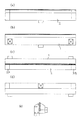
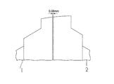
従来のコーティング用ダイヘッドは0.08mmの幅、長さ630mmのスリットを設けたSUSからなるヘッドからなっており、ヘッド先端部は、図2の断面図の様にR30の曲面を持つ。 A conventional coating die head is composed of a SUS head provided with a slit having a width of 0.08 mm and a length of 630 mm, and the head tip has a curved surface of R30 as shown in the sectional view of FIG.
これを用いた塗布によりバリが生じていたが、研磨でリップ先端部の全ての周囲のバリを取るのは困難であったので、そのバリの大きさに対応した塗布むらが生じていた。 Although burrs were generated by application using this, it was difficult to remove all burrs around the tip of the lip by polishing, so application unevenness corresponding to the size of the burrs occurred.
対して本願は、図1、図2及び図3に本発明の高精度コーティング用ダイヘッドにおける一実施例の説明図を示す。図1に示す実施例のヘッド先端部は、図2に示す様にR30の曲面を持つ。 On the other hand, this application shows the explanatory drawing of one Example in the die head for high precision coating of this invention in FIG.1, FIG2 and FIG.3. The head tip of the embodiment shown in FIG. 1 has a curved surface of R30 as shown in FIG.
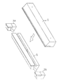
図1のヘッドをブロック化した場合の斜視図が図3で、大きく4つのブロックに分割される。前面のブロックである平面ヘッドブロック1、背面のブロックであるマニホールド側ヘッドブロック2、側面のブロックであるサイドブロック3A、3Bとからなる。図中の斜線部の部分がセラミックスのブロックで母材であるSUS製の本体と合体している。なお、この図3においては塗布液供給口は省略して描いている。
FIG. 3 is a perspective view of the head shown in FIG. 1 divided into blocks, which are roughly divided into four blocks. It consists of a
これが互いにネジ止めで固定されて、同サイズのスリットを持つものであるが、研磨した結果、バリは全くなくなり、バリに起因した塗布むらも観測できなかった。 These were fixed to each other by screws and had slits of the same size. However, as a result of polishing, no burrs were found, and coating unevenness due to burrs could not be observed.
また、この実施例では塗布開口部をシムで調整するタイプであるので、マニホールド側ヘッドブロック2の合わせ面は同じ厚みであるが、ヘッドの寸法で開口部の寸法を出すタイプのヘッドは開口部の設計値の寸法分厚みが異なる。
In this embodiment, since the coating opening is a type that is adjusted by a shim, the mating surface of the manifold-
図のようにヘッド先端から塗液圧力分散や均一化の為のマニホールド部にかかる部分まで超硬合金、もしくはセラミックスとする事で、膜厚形成部にかかわる部分の稜線は全て超硬合金、もしくはセラミックスとなり、切削もしくは研削加工においてバリを生じない。又マニホールド側を分割する事でマニホールドから塗膜形成部に至るエッジの部分の機械加工も側面から通し加工とすることで精度の向上が見込める。 As shown in the figure, the ridge line of the part related to the film thickness formation part is all made of cemented carbide or ceramic by using the cemented carbide or ceramics from the head tip to the part applied to the manifold part for dispersion and homogenization of coating liquid It becomes ceramic and does not cause burrs in cutting or grinding. In addition, by dividing the manifold side, machining of the edge part from the manifold to the coating film forming part can also be performed from the side, so that accuracy can be improved.
本発明は、精密薄膜コーティングを実現する各種コーティング用ダイヘッドに関するものである。 The present invention relates to various coating die heads that realize precision thin film coating.
1 平面ヘッドブロック
2 マニホールド側ヘッドブロック
3A、3B 側面のブロックであるサイドブロック
DESCRIPTION OF
Claims (2)
Priority Applications (1)
| Application Number | Priority Date | Filing Date | Title |
|---|---|---|---|
| JP2004117527A JP4759929B2 (en) | 2004-04-13 | 2004-04-13 | Die head for coating |
Applications Claiming Priority (1)
| Application Number | Priority Date | Filing Date | Title |
|---|---|---|---|
| JP2004117527A JP4759929B2 (en) | 2004-04-13 | 2004-04-13 | Die head for coating |
Publications (2)
| Publication Number | Publication Date |
|---|---|
| JP2005296828A true JP2005296828A (en) | 2005-10-27 |
| JP4759929B2 JP4759929B2 (en) | 2011-08-31 |
Family
ID=35329021
Family Applications (1)
| Application Number | Title | Priority Date | Filing Date |
|---|---|---|---|
| JP2004117527A Expired - Fee Related JP4759929B2 (en) | 2004-04-13 | 2004-04-13 | Die head for coating |
Country Status (1)
| Country | Link |
|---|---|
| JP (1) | JP4759929B2 (en) |
Cited By (4)
| Publication number | Priority date | Publication date | Assignee | Title |
|---|---|---|---|---|
| JP2006142248A (en) * | 2004-11-22 | 2006-06-08 | Dainippon Printing Co Ltd | Die head |
| JP2008036624A (en) * | 2006-07-12 | 2008-02-21 | Nitto Denko Corp | DIE, DIE TYPE COATING APPARATUS AND COATING METHOD |
| JP2020131119A (en) * | 2019-02-20 | 2020-08-31 | 株式会社タンガロイ | Die coater |
| WO2022015117A1 (en) * | 2020-07-16 | 2022-01-20 | 주식회사 엘지에너지솔루션 | Multiple slot die coater |
Citations (9)
| Publication number | Priority date | Publication date | Assignee | Title |
|---|---|---|---|---|
| JPS6295170A (en) * | 1985-10-18 | 1987-05-01 | Fuji Photo Film Co Ltd | Device for coating magnetic liquid |
| JPH0386079U (en) * | 1989-12-25 | 1991-08-30 | ||
| JPH06121953A (en) * | 1992-09-16 | 1994-05-06 | Mitsubishi Kasei Corp | Coating die with ceramic coating layer |
| JPH09141168A (en) * | 1995-11-17 | 1997-06-03 | Hitachi Maxell Ltd | Extrusion type coater head |
| JP2000140739A (en) * | 1998-11-10 | 2000-05-23 | Canon Inc | Single-wafer coating apparatus, and coating method and color filter manufacturing method using the same |
| JP2001029860A (en) * | 1999-07-19 | 2001-02-06 | Matsushita Electric Ind Co Ltd | Coating device |
| JP2001155335A (en) * | 1999-11-26 | 2001-06-08 | Sony Corp | Coating device and method of manufacturing magnetic recording medium |
| JP2004008989A (en) * | 2002-06-10 | 2004-01-15 | Hitachi Chem Co Ltd | Rigidly reinforced die |
| JP2004261678A (en) * | 2003-02-28 | 2004-09-24 | Mitsubishi Materials Corp | Coating tools and coating equipment |
-
2004
- 2004-04-13 JP JP2004117527A patent/JP4759929B2/en not_active Expired - Fee Related
Patent Citations (9)
| Publication number | Priority date | Publication date | Assignee | Title |
|---|---|---|---|---|
| JPS6295170A (en) * | 1985-10-18 | 1987-05-01 | Fuji Photo Film Co Ltd | Device for coating magnetic liquid |
| JPH0386079U (en) * | 1989-12-25 | 1991-08-30 | ||
| JPH06121953A (en) * | 1992-09-16 | 1994-05-06 | Mitsubishi Kasei Corp | Coating die with ceramic coating layer |
| JPH09141168A (en) * | 1995-11-17 | 1997-06-03 | Hitachi Maxell Ltd | Extrusion type coater head |
| JP2000140739A (en) * | 1998-11-10 | 2000-05-23 | Canon Inc | Single-wafer coating apparatus, and coating method and color filter manufacturing method using the same |
| JP2001029860A (en) * | 1999-07-19 | 2001-02-06 | Matsushita Electric Ind Co Ltd | Coating device |
| JP2001155335A (en) * | 1999-11-26 | 2001-06-08 | Sony Corp | Coating device and method of manufacturing magnetic recording medium |
| JP2004008989A (en) * | 2002-06-10 | 2004-01-15 | Hitachi Chem Co Ltd | Rigidly reinforced die |
| JP2004261678A (en) * | 2003-02-28 | 2004-09-24 | Mitsubishi Materials Corp | Coating tools and coating equipment |
Cited By (7)
| Publication number | Priority date | Publication date | Assignee | Title |
|---|---|---|---|---|
| JP2006142248A (en) * | 2004-11-22 | 2006-06-08 | Dainippon Printing Co Ltd | Die head |
| JP2008036624A (en) * | 2006-07-12 | 2008-02-21 | Nitto Denko Corp | DIE, DIE TYPE COATING APPARATUS AND COATING METHOD |
| JP2020131119A (en) * | 2019-02-20 | 2020-08-31 | 株式会社タンガロイ | Die coater |
| WO2022015117A1 (en) * | 2020-07-16 | 2022-01-20 | 주식회사 엘지에너지솔루션 | Multiple slot die coater |
| CN115379905A (en) * | 2020-07-16 | 2022-11-22 | 株式会社Lg新能源 | Multi-slit die coating machine |
| CN115379905B (en) * | 2020-07-16 | 2024-08-02 | 株式会社Lg新能源 | Multi-slit die coater |
| US12053796B2 (en) | 2020-07-16 | 2024-08-06 | Lg Energy Solution, Ltd. | Multi-slot die coater |
Also Published As
| Publication number | Publication date |
|---|---|
| JP4759929B2 (en) | 2011-08-31 |
Similar Documents
| Publication | Publication Date | Title |
|---|---|---|
| CN1974133B (en) | Method for manufacturing surface-coated cutting insert | |
| KR0177286B1 (en) | Milling cutter | |
| JP4759929B2 (en) | Die head for coating | |
| JP2003025118A (en) | Diamond tool for cutting | |
| JP2009119559A (en) | Cutting blade | |
| CN106825712A (en) | Milling cutting insert | |
| JP3542502B2 (en) | Manufacturing method of hydrostatic porous bearing | |
| JP3299523B2 (en) | Tool for turning groove of hard foam resin pad | |
| KR100668161B1 (en) | Polishing workpiece holder and manufacturing method thereof, polishing method of workpiece and polishing apparatus | |
| JPH11192452A (en) | Coating device, working for coater die, jig for coater die, grinding device, and coated product | |
| US6242709B1 (en) | Method for manufacturing conductive wafers, method for manufacturing thin-plate sintered compacts, method for manufacturing ceramic substrates for thin-film magnetic head, and method for machining conductive wafers | |
| JP3497492B2 (en) | Hard foam resin grooved pad for semiconductor device processing and pad turning groove processing tool | |
| JP2003136516A (en) | Mouthpiece for extrusion molding of honeycomb | |
| JP2005052820A (en) | Application tool and application device | |
| JP4261493B2 (en) | Dressing device, grinding device, dressing method, and numerical control program | |
| JPH10235553A (en) | Diamond lapping surface plate and manufacture therefor | |
| JP2008229537A (en) | DIE HEAD AND METHOD FOR PRODUCING LAMINATE | |
| WO2004009248A1 (en) | Die head for coating, coating device, and method of manufacturing die head for coating | |
| JP2000153553A (en) | Type roll | |
| JPS58149167A (en) | Manufacture of fluidized abrasive grain work jig | |
| CN100473467C (en) | Coating tool | |
| JP2006334748A (en) | Internal surface grinding wheel, grinding device and forming device | |
| JP2000061897A (en) | Water jetting nozzle | |
| KR20080039988A (en) | Applicator head | |
| JP4526027B2 (en) | Dressing device, grinding device, dressing method, and numerical control program |
Legal Events
| Date | Code | Title | Description |
|---|---|---|---|
| A621 | Written request for application examination |
Free format text: JAPANESE INTERMEDIATE CODE: A621 Effective date: 20070323 |
|
| A977 | Report on retrieval |
Free format text: JAPANESE INTERMEDIATE CODE: A971007 Effective date: 20091126 |
|
| A131 | Notification of reasons for refusal |
Free format text: JAPANESE INTERMEDIATE CODE: A131 Effective date: 20091201 |
|
| A521 | Written amendment |
Free format text: JAPANESE INTERMEDIATE CODE: A523 Effective date: 20100129 |
|
| A131 | Notification of reasons for refusal |
Free format text: JAPANESE INTERMEDIATE CODE: A131 Effective date: 20100817 |
|
| A521 | Written amendment |
Free format text: JAPANESE INTERMEDIATE CODE: A523 Effective date: 20101015 |
|
| A01 | Written decision to grant a patent or to grant a registration (utility model) |
Free format text: JAPANESE INTERMEDIATE CODE: A01 Effective date: 20110510 |
|
| A61 | First payment of annual fees (during grant procedure) |
Free format text: JAPANESE INTERMEDIATE CODE: A61 Effective date: 20110523 |
|
| FPAY | Renewal fee payment (prs date is renewal date of database) |
Free format text: PAYMENT UNTIL: 20140617 Year of fee payment: 3 |
|
| R150 | Certificate of patent (=grant) or registration of utility model |
Free format text: JAPANESE INTERMEDIATE CODE: R150 |
|
| LAPS | Cancellation because of no payment of annual fees |