JP2005296820A - Exhaust gas purification filter catalyst - Google Patents
Exhaust gas purification filter catalyst Download PDFInfo
- Publication number
- JP2005296820A JP2005296820A JP2004117203A JP2004117203A JP2005296820A JP 2005296820 A JP2005296820 A JP 2005296820A JP 2004117203 A JP2004117203 A JP 2004117203A JP 2004117203 A JP2004117203 A JP 2004117203A JP 2005296820 A JP2005296820 A JP 2005296820A
- Authority
- JP
- Japan
- Prior art keywords
- exhaust gas
- catalyst layer
- catalyst
- communication hole
- plates
- Prior art date
- Legal status (The legal status is an assumption and is not a legal conclusion. Google has not performed a legal analysis and makes no representation as to the accuracy of the status listed.)
- Withdrawn
Links
Images
Landscapes
- Exhaust Gas After Treatment (AREA)
- Processes For Solid Components From Exhaust (AREA)
- Filtering Materials (AREA)
- Exhaust Gas Treatment By Means Of Catalyst (AREA)
- Catalysts (AREA)
Abstract
【課題】PMを捕集し、捕集したPMを連続的にかつ効率よく酸化燃焼できるようにする。
【解決手段】金属薄板からなる波板及び平板が交互に積層され排ガス下流側で閉塞された流入側セル12と排ガス上流側で閉塞された流出側セル13とを有するフィルタ触媒であって、波板10及び平板11の少なくとも一方に表裏を貫通する連通孔14を形成し、触媒層3によって連通孔14を孔径が 200μm以下に縮径又は閉塞した。
PMを連通孔14に形成された触媒層3で捕集することができる。また触媒層3を均一に形成することができ、捕集されたPMを効率よく酸化燃焼することができる。また触媒層が均一であるので、その厚さを薄くすることができ、その結果排気圧損が低くなる。
【選択図】 図2An object of the present invention is to collect PM and make it possible to oxidize and burn the collected PM continuously and efficiently.
A filter catalyst having an inflow side cell (12) closed alternately on the exhaust gas downstream side and an outflow side cell (13) closed on the exhaust gas upstream side, in which corrugated plates and flat plates made of metal thin plates are alternately stacked. A communication hole 14 penetrating the front and back was formed in at least one of the plate 10 and the plate 11, and the communication hole 14 was reduced or closed to a diameter of 200 μm or less by the catalyst layer 3.
PM can be collected by the catalyst layer 3 formed in the communication hole 14. Further, the catalyst layer 3 can be formed uniformly, and the collected PM can be oxidized and burned efficiently. Further, since the catalyst layer is uniform, the thickness thereof can be reduced, and as a result, the exhaust pressure loss is reduced.
[Selection] Figure 2
Description
本発明は、ディーゼルエンジンなどからの排ガス中の粒子状物質(以下、PMという)を捕集する排ガス浄化フィルタ触媒に関する。 The present invention relates to an exhaust gas purification filter catalyst that collects particulate matter (hereinafter referred to as PM) in exhaust gas from a diesel engine or the like.
ディーゼルエンジンなどからの排ガス中には、カーボン微粒子、 SOF、サルフェート類などからなるPMが含まれているため、排出前にPMを除去して清浄な排ガスを排出する必要がある。このPMは、通常の酸化触媒、三元触媒などでは除去することが困難であるため、フィルタに捕集した後に酸化除去する方法が一般的である。 Since exhaust gas from diesel engines, etc. contains PM composed of carbon fine particles, SOF, sulfates, etc., it is necessary to remove PM before discharging to discharge clean exhaust gas. Since this PM is difficult to remove with a normal oxidation catalyst, a three-way catalyst or the like, a method of oxidizing and removing the PM after collecting it on a filter is common.
このようなフィルタとしては、コーディエライトなどの耐熱性セラミックスからなり多数のセルをもつハニカム体に、下流側端部で目詰めされた流入側セルと、流入側セルに隣接し上流側端部で目詰めされた流出側セルを形成したウォールフロー型のもの( DPF)が広く用いられている。この DPFでは、流入側セルに流入した排ガスがセル隔壁を通過して流出側セルから排出されるが、排ガスがセル隔壁を通過する際にPMがセル隔壁の細孔中に捕集される。そしてPMがある程度捕集されると、ヒータによる加熱などで捕集されたPMを燃焼させフィルタ機能を再生することが行われる。 As such a filter, a honeycomb body made of heat-resistant ceramics such as cordierite and having a large number of cells, an inflow side cell clogged at the downstream end, and an upstream end adjacent to the inflow side cell Wall-flow type (DPF) is widely used, which forms outflow side cells clogged with. In this DPF, the exhaust gas flowing into the inflow side cell passes through the cell partition and is discharged from the outflow side cell. However, when the exhaust gas passes through the cell partition, PM is collected in the pores of the cell partition. When PM is collected to some extent, PM collected by heating with a heater is burned to regenerate the filter function.
しかしこのようなフィルタでは、PM捕集量が多い場合などには再生時の燃焼による発熱量が大きく、ヒートショックによって損傷する場合がある。また製造コストも高い。そこで近年では、金属製のフィルタ装置がいくつか提案されている。 However, with such a filter, when the amount of collected PM is large, the amount of heat generated by combustion during regeneration is large, and may be damaged by heat shock. In addition, the manufacturing cost is high. Therefore, in recent years, several metal filter devices have been proposed.
たとえば特開平09−262414号公報には、金属薄板からなる波板と金属不織布からなる平板とを交互に積層し、下流側端部で目詰めされた流入側セルと、流入側セルに隣接し上流側端部で目詰めされた流出側セルと、を形成したフィルタが記載されている。また特開2002−113798号公報には、金属不織布からなる平板と波板とを交互に積層し、下流側端部で目詰めされた流入側セルと、流入側セルに隣接し上流側端部で目詰めされた流出側セルと、を形成したフィルタが記載されている。 For example, in Japanese Patent Application Laid-Open No. 09-262414, a corrugated plate made of a thin metal plate and a flat plate made of a metal non-woven fabric are alternately laminated, and an inflow side cell clogged at a downstream end portion is adjacent to the inflow side cell. A filter is described which forms an outflow side cell clogged at an upstream end. Further, JP 2002-113798 A discloses an inflow side cell in which flat plates and corrugated plates made of a metal nonwoven fabric are alternately laminated and clogged at a downstream end, and an upstream end adjacent to the inflow side cell. And a filter formed with an outflow side cell clogged with.
これらのフィルタによれば、排ガス中のPMは金属不織布中に捕集される。そして加熱によってPMを燃焼させる再生処理を行っても、金属製であるためヒートショックが小さく損傷を抑制することができる。ところがいずれもウォールフロー型のフィルタであるので、PMの捕集に伴って排気圧損が上昇する。しかも流入側セルの目詰め部近傍にPMが集中して堆積するため排気圧損が一気に上昇するという不具合があり、エンジン効率や燃費などを重視する場合には再生処理を頻繁に行う必要がある。 According to these filters, PM in the exhaust gas is collected in the metal nonwoven fabric. And even if it performs the regeneration process which burns PM by heating, since it is metal, a heat shock is small and damage can be suppressed. However, since both are wall flow type filters, exhaust pressure loss increases as PM is collected. In addition, since PM concentrates and accumulates in the vicinity of the clogging portion of the inflow side cell, there is a problem that exhaust pressure loss increases at a stretch. When importance is attached to engine efficiency or fuel consumption, it is necessary to frequently perform regeneration processing.
一方、独国特許 20,117,873 U1号には、金属フォイル製の波板とフィルタ層とを交互に積層し、波板に爪状穴高さを有する複数の爪状穴を形成し、複数の爪状穴は内向爪状穴と外向爪状穴とを有する流路を形成し、内向爪状穴と外向爪状穴とは互いに角をなして配置され、爪状穴高さは構造高さの 100〜60%の高さがあり少なくとも20%の流動自由度が保証されたフィルタが記載されている。 On the other hand, in German Patent No. 20,117,873 U1, a corrugated plate made of metal foil and a filter layer are alternately laminated, and a plurality of claw-shaped holes having claw-shaped hole heights are formed on the corrugated plate. The hole forms a flow path having an inward claw-like hole and an outward claw-like hole, and the inward claw-like hole and the outward claw-like hole are arranged at an angle with each other. A filter is described which is ˜60% high and guarantees a flow freedom of at least 20%.
このフィルタによれば、爪状穴から出る排ガスがフィルタ層を通過することでPMがフィルタ層に捕集される。また主としてストレートフロー構造であるので、排気圧損の増大も抑制される。しかし基本的にストレートフロー構造であるので、PMの捕集効率が低いという欠点がある。 According to this filter, PM is collected in the filter layer by the exhaust gas coming out of the claw-shaped holes passing through the filter layer. In addition, since the straight flow structure is mainly used, an increase in exhaust pressure loss is also suppressed. However, since it is basically a straight flow structure, there is a drawback that the PM collection efficiency is low.
また触媒機能を付与したフィルタ触媒も開発されている。例えば特開平09−262415号公報には、連続空孔を有する耐熱金属製3次元網状構造多孔体又はその多孔体の孔に、セラミックもしくは金属を充填して実質孔径を小さくしたもので作られる平板フィルタと波板を交互に重ねて巻回してなり、これによって出来る柱状体の両端を各々交互に目留めしてなるフィルタエレメントが記載され、波板又は平板エレメントに触媒金属を担持することが記載されている。 A filter catalyst having a catalytic function has also been developed. For example, Japanese Patent Application Laid-Open No. 09-262415 discloses a three-dimensional network structure porous body made of heat-resistant metal having continuous pores, or a plate made by filling ceramic or metal into pores of the porous body to reduce the substantial pore diameter. A filter element is described in which a filter and a corrugated plate are alternately stacked and wound, and both ends of a columnar body formed thereby are alternately noted. Has been.
このフィルタエレメントによれば、PMトラップと触媒コンバータを一体化することができ、スペース面で有利である。また担持体が金属であるので、熱容量が小さく触媒金属の昇温速度が早くなり、触媒金属が効果的に働くのに必要な温度を得ることも容易となる。さらに、触媒金属としてアルカリ金属などのNOx 吸蔵材を担持した場合には、コーディエライトなどからなる基体の場合にはNOx 吸蔵材と基体が反応するが、金属製の基体であればNOx 吸蔵材と反応しないという利点がある。 According to this filter element, the PM trap and the catalytic converter can be integrated, which is advantageous in terms of space. Further, since the carrier is a metal, the heat capacity is small and the temperature rise rate of the catalyst metal is increased, and it becomes easy to obtain a temperature necessary for the catalyst metal to work effectively. Further, when carrying the NO x storage material such as alkali metal as a catalyst metal is in the case of a substrate made of cordierite reacts is the NO x storage material and the substrate, if the metal substrate NO x Has the advantage of not reacting with the occlusion material.
しかしながら特開平09−262415号公報に記載の技術では、連続空孔を有する耐熱金属製3次元網状構造多孔体を用いているので、孔径がランダムである。触媒を担持するには、触媒金属を担持した多孔質酸化物を含む触媒層を形成するのが効果的であるが、孔径がランダムな耐熱金属製3次元網状構造多孔体に均一な触媒層を形成することは困難であり、排気圧損の上昇が大きくなったり、触媒金属による活性が十分に得られなかったり、使用時の熱によって触媒金属の粒成長が生じて活性が低下するという問題があった。
本発明は上記した事情に鑑みてなされたものであり、PMを捕集し、捕集したPMを連続的にかつ効率よく酸化燃焼できるようにすることを解決すべき課題とする。 The present invention has been made in view of the above-described circumstances, and an object to be solved is to collect PM and enable the collected PM to be oxidized and burned continuously and efficiently.
上記課題を解決する本発明の排ガス浄化フィルタ触媒の特徴は、金属薄板からなる波板及び平板が交互に積層されてなり、波板及び平板で形成される複数のセルを有するとともに波板及び平板の少なくとも一方には表裏を貫通する連通孔を備え、セルは排ガス下流側で閉塞された流入側セルと、流入側セルに隣接し排ガス上流側で閉塞された流出側セルとを有する基体と、
連通孔を有する波板及び平板の少なくとも一方の表面に形成され、触媒金属が担持された多孔質酸化物を含む触媒層と、からなり、触媒層によって連通孔は孔径が 200μm以下に縮径又は閉塞されていることにある。
A feature of the exhaust gas purifying filter catalyst of the present invention that solves the above problems is that a corrugated plate and a flat plate made of metal thin plates are alternately laminated, and has a plurality of cells formed by the corrugated plate and the flat plate, and the corrugated plate and the flat plate. At least one of the above is provided with a communication hole penetrating the front and back, the cell has an inflow side cell closed on the exhaust gas downstream side, and a base having an outflow side cell adjacent to the inflow side cell and closed on the exhaust gas upstream side,
A catalyst layer including a porous oxide formed on at least one surface of a corrugated plate and a flat plate having a communication hole and supporting a catalytic metal. The communication layer has a pore diameter reduced to 200 μm or less by the catalyst layer. It is in the blockage.
波板は触媒層が形成され排ガスが衝突する切欠きを有し、切欠きに衝突した排ガスが連通孔を通過するように構成されていることが望ましい。 It is desirable that the corrugated plate has a notch where a catalyst layer is formed and the exhaust gas collides, and the exhaust gas that collides with the notch passes through the communication hole.
本発明の排ガス浄化フィルタ触媒によれば、連通孔は触媒層によって孔径が 200μm以下に縮径又は閉塞されているので、排ガス中のPMを連通孔に形成された触媒層で捕集し浄化することができる。そして金属薄板に触媒層を形成しているので、触媒層を均一に形成することができ、排ガスによって触媒層が均一に加熱され触媒金属も均一に活性化されるため、捕集されたPMを効率よく酸化燃焼することができる。また触媒層が均一であるので、その厚さを薄くすることができ、その結果排気圧損が低くなる。 According to the exhaust gas purification filter catalyst of the present invention, since the communication hole is reduced or closed to a diameter of 200 μm or less by the catalyst layer, PM in the exhaust gas is collected and purified by the catalyst layer formed in the communication hole. be able to. Since the catalyst layer is formed on the metal thin plate, the catalyst layer can be formed uniformly, and the catalyst layer is heated uniformly by the exhaust gas and the catalyst metal is also activated uniformly. It can be oxidized and burned efficiently. Further, since the catalyst layer is uniform, the thickness thereof can be reduced, and as a result, the exhaust pressure loss is reduced.
さらに波板に触媒層が形成され排ガスが衝突する切欠きを有し、切欠きに衝突した排ガスが連通孔を通過するように構成されていれば、波板に形成された触媒層で排ガス中のNOが酸化され、酸化活性の高いNO2 となって連通孔を通過するので、連通孔に形成された触媒層に捕集されたPMの酸化燃焼がさらに促進される。 Furthermore, if the catalyst layer is formed on the corrugated plate and the exhaust gas collides with the notch, and the exhaust gas colliding with the notch is configured to pass through the communication hole, the catalyst layer formed on the corrugated plate may NO is oxidized and becomes NO 2 having high oxidation activity and passes through the communication hole, so that the oxidative combustion of PM collected in the catalyst layer formed in the communication hole is further promoted.
本発明の排ガス浄化フィルタ触媒では、連通孔は触媒層によって孔径が 200μm以下に縮径又は閉塞されている。孔径が 200μmの場合、初期状態では 200μmの孔からPMがすり抜けるものもあるが、PMが付着してくると孔径が10〜50μm程度となってPM捕集能が向上するので、孔径を 200μm以下とした。なお触媒層は多孔質酸化物粉末を含むため、触媒層自体にも10μm程度の細孔が存在し、多孔質酸化物粉末にもさらに微細な細孔が存在する。したがって連通孔が触媒層で完全に閉塞されていても、ガス拡散性は確保され、連通孔に形成された触媒層に捕集されたPMは触媒金属によって効率よく酸化燃焼される。 In the exhaust gas purifying filter catalyst of the present invention, the communication hole is reduced or closed to a diameter of 200 μm or less by the catalyst layer. When the pore size is 200 μm, PM may slip through the 200 μm hole in the initial state, but when PM adheres, the pore size becomes about 10 to 50 μm and the PM collection ability is improved, so the pore size is less than 200 μm. It was. Since the catalyst layer contains porous oxide powder, pores of about 10 μm are present in the catalyst layer itself, and finer pores are also present in the porous oxide powder. Therefore, even if the communication hole is completely blocked by the catalyst layer, gas diffusibility is ensured, and PM collected in the catalyst layer formed in the communication hole is efficiently oxidized and burned by the catalyst metal.
波板及び平板は、金属薄板から形成されたものであり、波板は平板からコルゲート加工などにより製造することができる。その材質は、排ガス温度及び再生時の熱に耐え得る以上の耐熱性を有すれば特に制限されないが、ステンレス鋼材が好ましい。また自動車用の場合には、厚さは20〜 110μmの範囲が好ましく、40〜80μmの範囲が特に好ましい。 The corrugated plate and the flat plate are formed from a thin metal plate, and the corrugated plate can be manufactured from the flat plate by corrugating or the like. The material is not particularly limited as long as it has heat resistance that can withstand the exhaust gas temperature and heat during regeneration, but a stainless steel material is preferable. For automobiles, the thickness is preferably in the range of 20 to 110 μm, particularly preferably in the range of 40 to 80 μm.
波板及び平板の少なくとも一方には、表裏を貫通する連通孔を備えている。この連通孔は、30〜 500μmの大きさとすることが好ましい。連通孔の大きさが 500μmを超えると触媒層によって 200μm以下に閉塞することが困難となり、30μm未満では触媒層によって閉塞される結果、ガス拡散性は確保されるものの排気圧損が上昇しやすい。連通孔の数には特に制限がないが、基体の強度が維持できる範囲でできるだけ多く設けることが好ましい。 At least one of the corrugated plate and the flat plate is provided with a communication hole penetrating the front and back. It is preferable that the communication hole has a size of 30 to 500 μm. If the size of the communication hole exceeds 500 μm, it becomes difficult to close the surface to 200 μm or less by the catalyst layer, and if it is less than 30 μm, the catalyst layer closes the gas. The number of communication holes is not particularly limited, but it is preferable to provide as many as possible within a range where the strength of the substrate can be maintained.
基体を形成するには、波板と平板とを交互に積層して所定の外筒に挿入してもよいし、所定長さの波板と平板とを重ねてロール状に巻回したものを所定の外筒に挿入することもできる。また排ガス下流側で閉塞された流入側セルと、流入側セルに隣接し排ガス上流側で閉塞された流出側セルを形成するには、金属製などの栓部材でセルを目詰めする方法、あるいは耐熱性セラミックス製のフィルタと同様に粘土状のスラリーを詰めた後に焼成して形成する方法、あるいは波板を挟んだ2枚の平板の端部を排ガス入り口側と出口側で交互に接合する方法、などを採用できる。 In order to form the substrate, corrugated plates and flat plates may be alternately stacked and inserted into a predetermined outer cylinder, or a corrugated plate and flat plate of a predetermined length may be stacked and wound into a roll shape. It can also be inserted into a predetermined outer cylinder. In order to form an inflow side cell blocked on the exhaust gas downstream side and an outflow side cell adjacent to the inflow side cell and blocked on the exhaust gas upstream side, a method of clogging the cells with a plug member made of metal or the like, or A method of forming by baking after filling with clay-like slurry like a filter made of heat-resistant ceramics, or a method of joining the ends of two flat plates sandwiching corrugated plates alternately on the exhaust gas inlet side and outlet side , Etc. can be adopted.
触媒層は、触媒金属が担持された多孔質酸化物を含む層であり、基体1リットルあたり30〜 200gの量で形成されていることが望ましい。触媒層の量がこれより少ないと触媒金属が高密度で担持されることとなるため触媒金属に粒成長が生じたり、PMの捕集効率が低下する。また触媒層がこれより多くなると、排気圧損が上昇するようになる。多孔質酸化物としては、アルミナ、ジルコニア、チタニア、セリアなどから選ばれる少なくとも一種、あるいはこれらから選ばれる複数種からなる複合酸化物などを用いることができる。触媒金属としては、Pt、Rh、Pd、Ir、Ruなどの白金族の貴金属から選ばれた一種あるいは複数種を用いることが好ましい。触媒金属の担持量は、基体1Lあたり 0.1〜5gとするのが好ましい。担持量がこれより少ないと活性が低すぎて実用的でなく、この範囲より多く担持しても活性が飽和するとともにコストアップとなってしまう。 The catalyst layer is a layer containing a porous oxide on which a catalyst metal is supported, and is preferably formed in an amount of 30 to 200 g per liter of the substrate. If the amount of the catalyst layer is smaller than this, the catalyst metal is supported at a high density, so that grain growth occurs in the catalyst metal or PM collection efficiency decreases. Further, when the catalyst layer is larger than this, the exhaust pressure loss increases. As the porous oxide, it is possible to use at least one selected from alumina, zirconia, titania, ceria, and the like, or a composite oxide composed of a plurality of types selected from these. As the catalyst metal, it is preferable to use one or more selected from platinum group noble metals such as Pt, Rh, Pd, Ir and Ru. The amount of catalyst metal supported is preferably 0.1 to 5 g per liter of the substrate. If the loading amount is less than this, the activity is too low to be practical, and if the loading amount exceeds this range, the activity is saturated and the cost is increased.
触媒層には、アルカリ金属、アルカリ土類金属及び希土類元素から選ばれるNOx 吸蔵材を含むことが望ましい。触媒層にNOx 吸蔵材を含めば、触媒金属による酸化によって生成したNO2 をNOx 吸蔵材に吸蔵できるので、NOx の浄化活性がさらに向上する。NOx 吸蔵材の担持量は、基体1リットルあたり0.05〜0.45モルの範囲とすることが好ましい。担持量がこれより少ないと活性が低すぎて実用的でなく、この範囲より多く担持すると触媒金属を覆って活性が低下するようになる。 The catalyst layer preferably contains a NO x storage material selected from alkali metals, alkaline earth metals, and rare earth elements. When the NO x storage material is included in the catalyst layer, NO 2 generated by oxidation with the catalyst metal can be stored in the NO x storage material, so that the NO x purification activity is further improved. The amount of NO x occlusion material supported is preferably in the range of 0.05 to 0.45 mol per liter of substrate. If the supported amount is less than this, the activity is too low to be practical, and if the supported amount is more than this range, the catalyst metal is covered and the activity is lowered.
基体に触媒層を形成するには、酸化物粉末あるいは複合酸化物粉末をアルミナゾルなどのバインダ成分及び水とともにスラリーとし、そのスラリーを波板及び平板の少なくとも一方に付着させた後に焼成し、その後に触媒金属を担持すればよい。また酸化物粉末あるいは複合酸化物粉末に予め触媒金属を担持した触媒粉末からスラリーを調製することもできる。スラリーを付着させるには通常の浸漬法を用いることができるが、エアブローあるいは吸引によって、連通孔に強制的にスラリーを充填するとともに、連通孔内に入ったスラリーの余分なものを除去することが望ましい。 In order to form a catalyst layer on a substrate, oxide powder or composite oxide powder is made into a slurry together with a binder component such as alumina sol and water, and the slurry is attached to at least one of a corrugated plate and a flat plate, and then fired. What is necessary is just to carry | support a catalyst metal. A slurry can also be prepared from a catalyst powder in which a catalyst metal is previously supported on an oxide powder or a composite oxide powder. A normal dipping method can be used to attach the slurry, but it is possible to forcibly fill the communicating holes with air blow or suction and to remove excess slurry contained in the communicating holes. desirable.
波板は触媒層が形成され排ガスが衝突する切欠きを有し、切欠きに衝突した排ガスが触媒層が形成された連通孔を通過するように構成されていることが望ましい。この場合には、波板に形成された触媒層で排ガス中のNOが酸化され、酸化活性の高いNO2 となって連通孔を通過するので、連通孔の触媒層に捕集されたPMの酸化燃焼がさらに促進される。したがってこの場合には、触媒層は波板及び平板の両方に形成することが望ましい。 It is desirable that the corrugated plate has a notch in which a catalyst layer is formed and exhaust gas collides, and the exhaust gas that has collided with the notch passes through a communication hole in which the catalyst layer is formed. In this case, NO in the exhaust gas is oxidized by the catalyst layer formed on the corrugated plate and becomes NO 2 having high oxidation activity and passes through the communication hole, so that the PM trapped in the catalyst layer of the communication hole Oxidative combustion is further promoted. Therefore, in this case, it is desirable to form the catalyst layer on both the corrugated plate and the flat plate.
以下、実施例及び比較例により本発明を具体的に説明する。 Hereinafter, the present invention will be specifically described with reference to Examples and Comparative Examples.
(実施例1)
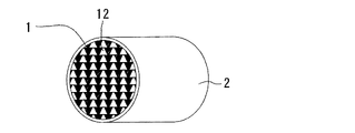
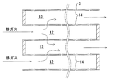
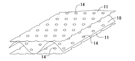
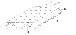
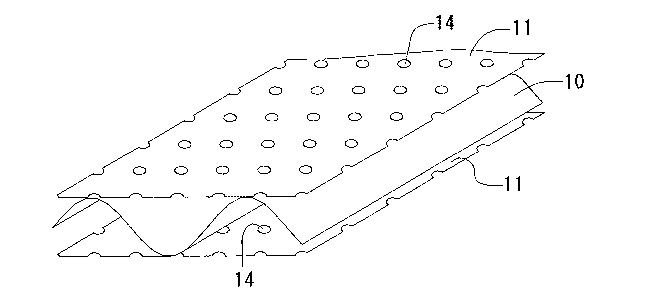
図1に本実施例の排ガス浄化フィルタ触媒の斜視図を、図2にその要部拡大断面図を、図3に用いた基体の要部拡大斜視図を示す。このフィルタ触媒は、ステンレス鋼よりなり厚さ50μmの波板10と、ステンレス鋼よりなり厚さ50μmの平板11とが交互に積層され互いに溶接されてなる基体1と、基体1が圧入保持された外筒2と、から構成されている。基体1は直径 130mmで2Lの体積を有し、セル数は 200個/inch2 であって、排ガス下流側で一つおきに交互に目詰めされた流入側セル12と、流入側セル12に隣接し排ガス下流側で目詰めされていないセルを排ガス上流側で目詰めした流出側セル13と、を有している。
(Example 1)
FIG. 1 is a perspective view of an exhaust gas purification filter catalyst of the present embodiment, FIG. 2 is an enlarged cross-sectional view of the main part thereof, and an enlarged perspective view of the main part of the substrate used in FIG. This filter catalyst has a
波板10及び平板11には、それぞれ直径 0.2mmの連通孔14が 0.2mm毎に穿設されている。また波板10及び平板11の表裏面には、それぞれ触媒層3が形成されている。この触媒層3は、Ptが担持されたアルミナ粉末から構成され、スラリーを用いてウォッシュコート後に焼成されてなる。触媒層3は平均細孔径10μmの細孔を有し、基体1の1リットルあたり 150g形成され、Ptが基体1リットルあたり2g担持されている。また触媒層3によって連通孔14の径が縮小され、約 100μmとなっている。
The
このフィルタ触媒では、流入側セル12に流入した排ガスは連通孔14を通過して流出側セル13に流入し、その際にPMは、触媒層3の細孔及び連通孔14で捕集される。また排ガス中のHC、CO、及び捕集されたPMは、触媒層3に担持されたPtによって酸化されて浄化される。
In this filter catalyst, the exhaust gas flowing into the
このフィルタ触媒をディーゼルエンジンの排気管に装着し、11 LapモードにおけるPM低減率、運転後期における排気圧損、PM残存量を測定した。PM低減率は、フィルタ触媒を通過した排ガス中のPM量(P1 )を測定し、予めわかっているディーゼルエンジンから排出されるPM総量(P0 )から次式によって算出した。 This filter catalyst was attached to the exhaust pipe of a diesel engine, and the PM reduction rate in the 11 Lap mode, the exhaust pressure loss in the latter period of operation, and the PM remaining amount were measured. The PM reduction rate was calculated by measuring the PM amount (P 1 ) in the exhaust gas that passed through the filter catalyst and calculating the PM amount (P 0 ) discharged from the diesel engine in advance by the following equation.
PM低減率(%)= 100×(P0 −P1 )/P0
排気圧損は、11 Lapモードで1000km走行した時のフィルタ触媒入りガスの圧力とフィルタ触媒出ガスの圧力との差を測定した。またPM残存量は、11 Lapモードで1000kmの運転後にフィルタ触媒の重量を測定し、運転前の重量との差を算出した。結果を表1に示す。
PM reduction rate (%) = 100 x (P 0 -P 1 ) / P 0
The exhaust pressure loss was measured by measuring the difference between the pressure of the gas containing the filter catalyst and the pressure of the gas output from the filter catalyst when the vehicle traveled 1000 km in the 11 Lap mode. The PM remaining amount was calculated by measuring the weight of the filter catalyst after 1000 km operation in 11 Lap mode, and calculating the difference from the weight before operation. The results are shown in Table 1.
(比較例1)
波板10及び平板11に代えて、厚さ 0.3mm、気孔率80%の金属製ファイバーマットから形成された波板と平板を用いたこと以外は実施例1と同様である。このフィルタ触媒を用い、実施例1と同様にしてPM低減率、排気圧損、PM残存量をそれぞれ測定した。結果を表1に示す。
(Comparative Example 1)
Instead of the
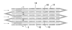
(実施例2)
図4に本実施例の排ガス浄化フィルタ触媒の断面図を、図5に用いた基体の要部拡大斜視図を示す。このフィルタ触媒は、目詰めされていない波板10を挟んだ2枚の平板11の端部を、排ガス入り口側と出口側で交互に接合し、平板11のみに連通孔14が形成されて、平板11によるウォールフロー構造となっている。波板10は流入側セル12及び流出側セル13の仕切保持材となっている。また触媒層3は、平板11の表面のみに形成されている。他の構成は実施例1と同様である。
(Example 2)
FIG. 4 shows a cross-sectional view of the exhaust gas purifying filter catalyst of the present embodiment, and FIG. In this filter catalyst, the end portions of two
このように構成した基材を用いても、実施例1と同様の作用効果が奏される。また平板11の両端を交互に接合するだけでよいので、目詰めする実施例1に比べて製造工数が低減され、重量も軽減される。
Even if the base material configured as described above is used, the same effects as those of the first embodiment can be obtained. Further, since both ends of the
<評価> <Evaluation>
実施例1と比較例1との比較より、実施例1のフィルタ触媒は比較例1に比べてPM捕集能に優れ、かつ排気圧損が低い。またPM残存量が少なく、フィルタの再生性能にも優れている。これは、実施例1では金属薄板よりなる波板と平板に触媒層を形成したので、ファイバーマットに触媒層を形成した比較例1に比べて触媒層が均一に形成され、Ptも均一に分布した効果である。 From the comparison between Example 1 and Comparative Example 1, the filter catalyst of Example 1 is superior to Comparative Example 1 in PM trapping ability and has low exhaust pressure loss. Also, the amount of remaining PM is small, and the filter regeneration performance is also excellent. In Example 1, since the catalyst layer was formed on the corrugated plate and the flat plate made of a thin metal plate, the catalyst layer was formed more uniformly than in Comparative Example 1 in which the catalyst layer was formed on the fiber mat, and Pt was also distributed uniformly. Effect.
1:基体 2:外筒 3:触媒層
4:波板 10:波板 11:平板
12:流入側セル 13:流出側セル 14:連通孔
1: Substrate 2: Outer cylinder 3: Catalyst layer 4: Corrugated plate 10: Corrugated plate 11: Flat plate
12: Inflow side cell 13: Outflow side cell 14: Communication hole
Claims (2)
該連通孔を有する該波板及び該平板の少なくとも一方の表面に形成され、触媒金属が担持された多孔質酸化物を含む触媒層と、からなり、
該触媒層によって該連通孔は孔径が 200μm以下に縮径又は閉塞されていることを特徴とする排ガス浄化フィルタ触媒。 Corrugated plates and flat plates made of thin metal plates are alternately laminated, and have a plurality of cells formed by the corrugated plates and the flat plates, and at least one of the corrugated plates and the flat plates has a communication hole penetrating the front and back. A base body having an inflow side cell closed on the exhaust gas downstream side and an outflow side cell adjacent to the inflow side cell and closed on the exhaust gas upstream side;
The corrugated plate having the communication holes and a catalyst layer formed on at least one surface of the flat plate and containing a porous oxide on which a catalytic metal is supported;
The exhaust gas purifying filter catalyst, wherein the communication hole is reduced or closed to a diameter of 200 μm or less by the catalyst layer.
Priority Applications (1)
| Application Number | Priority Date | Filing Date | Title |
|---|---|---|---|
| JP2004117203A JP2005296820A (en) | 2004-04-12 | 2004-04-12 | Exhaust gas purification filter catalyst |
Applications Claiming Priority (1)
| Application Number | Priority Date | Filing Date | Title |
|---|---|---|---|
| JP2004117203A JP2005296820A (en) | 2004-04-12 | 2004-04-12 | Exhaust gas purification filter catalyst |
Publications (1)
| Publication Number | Publication Date |
|---|---|
| JP2005296820A true JP2005296820A (en) | 2005-10-27 |
Family
ID=35329013
Family Applications (1)
| Application Number | Title | Priority Date | Filing Date |
|---|---|---|---|
| JP2004117203A Withdrawn JP2005296820A (en) | 2004-04-12 | 2004-04-12 | Exhaust gas purification filter catalyst |
Country Status (1)
| Country | Link |
|---|---|
| JP (1) | JP2005296820A (en) |
Cited By (6)
| Publication number | Priority date | Publication date | Assignee | Title |
|---|---|---|---|---|
| WO2007114495A1 (en) * | 2006-03-29 | 2007-10-11 | Toyota Jidosha Kabushiki Kaisha | Exhaust emission control catalyst and exhaust emission control system |
| JP2008280864A (en) * | 2007-05-08 | 2008-11-20 | Nichidai Filter Corp | Exhaust gas filter device |
| JP2013501615A (en) * | 2009-08-11 | 2013-01-17 | ビー・エイ・エス・エフ、コーポレーション | Particulate air filter equipped with ozone catalyst and method for producing and using the same |
| WO2019194881A1 (en) * | 2018-04-05 | 2019-10-10 | Catalytic Combustion Corporation | Metal foil catalyst for the control of emissions from diesel engines |
| JP2020075199A (en) * | 2018-11-05 | 2020-05-21 | 株式会社Soken | Exhaust gas purification filter and manufacturing method thereof |
| WO2021251105A1 (en) * | 2020-06-12 | 2021-12-16 | 日鉄ケミカル&マテリアル株式会社 | Catalyst carrying base material and catalyst converter |
-
2004
- 2004-04-12 JP JP2004117203A patent/JP2005296820A/en not_active Withdrawn
Cited By (9)
| Publication number | Priority date | Publication date | Assignee | Title |
|---|---|---|---|---|
| WO2007114495A1 (en) * | 2006-03-29 | 2007-10-11 | Toyota Jidosha Kabushiki Kaisha | Exhaust emission control catalyst and exhaust emission control system |
| JP2008280864A (en) * | 2007-05-08 | 2008-11-20 | Nichidai Filter Corp | Exhaust gas filter device |
| JP2013501615A (en) * | 2009-08-11 | 2013-01-17 | ビー・エイ・エス・エフ、コーポレーション | Particulate air filter equipped with ozone catalyst and method for producing and using the same |
| WO2019194881A1 (en) * | 2018-04-05 | 2019-10-10 | Catalytic Combustion Corporation | Metal foil catalyst for the control of emissions from diesel engines |
| US11351502B2 (en) | 2018-05-04 | 2022-06-07 | Catalytic Combustion Corporation | Metal foil catalyst for the control of emissions from diesel engines |
| US11759747B2 (en) | 2018-05-04 | 2023-09-19 | Catalytic Combustion Corporation | Metal foil catalyst for the control of emissions from diesel engines |
| JP2020075199A (en) * | 2018-11-05 | 2020-05-21 | 株式会社Soken | Exhaust gas purification filter and manufacturing method thereof |
| JP7146579B2 (en) | 2018-11-05 | 2022-10-04 | 株式会社Soken | Exhaust gas purification filter and its manufacturing method |
| WO2021251105A1 (en) * | 2020-06-12 | 2021-12-16 | 日鉄ケミカル&マテリアル株式会社 | Catalyst carrying base material and catalyst converter |
Similar Documents
| Publication | Publication Date | Title |
|---|---|---|
| JP3872384B2 (en) | Exhaust gas purification filter catalyst | |
| KR100692356B1 (en) | Honeycomb structure | |
| JP6023395B2 (en) | Catalyst support filter | |
| JP5639343B2 (en) | Honeycomb catalyst body | |
| JP2001190916A (en) | Honeycomb structure | |
| JP2004105792A (en) | Exhaust gas purification filter catalyst and method for producing the same | |
| JP2010269205A (en) | Exhaust gas purification catalyst | |
| JP4715032B2 (en) | Diesel exhaust gas purification filter | |
| JP4868713B2 (en) | Exhaust gas purification filter device | |
| JP4347120B2 (en) | Exhaust gas purification device | |
| JP4471621B2 (en) | Honeycomb structure | |
| JP2005296820A (en) | Exhaust gas purification filter catalyst | |
| JP2009228618A (en) | Exhaust emission control device | |
| JP4868714B2 (en) | Exhaust gas purification filter catalyst | |
| JP4357776B2 (en) | Exhaust gas purification honeycomb structure | |
| JP4285342B2 (en) | Manufacturing method of exhaust gas purification filter | |
| JP2007125524A (en) | Exhaust gas purification device | |
| JP2006077672A (en) | Exhaust gas purification filter and exhaust gas purification device | |
| JP2009011921A (en) | Diesel exhaust gas purification filter | |
| JP2001205108A (en) | Particulate filter | |
| JP3871197B2 (en) | Particulate filter | |
| JP2006231116A (en) | Exhaust gas purification filter catalyst | |
| JP2008151100A (en) | Exhaust gas purification device | |
| JP4358054B2 (en) | Exhaust gas purification honeycomb structure | |
| JP3874258B2 (en) | Exhaust gas purification device |
Legal Events
| Date | Code | Title | Description |
|---|---|---|---|
| A621 | Written request for application examination |
Free format text: JAPANESE INTERMEDIATE CODE: A621 Effective date: 20070108 |
|
| A761 | Written withdrawal of application |
Free format text: JAPANESE INTERMEDIATE CODE: A761 Effective date: 20081224 |