JP2005296813A - Ultrasonic cleaner - Google Patents
Ultrasonic cleaner Download PDFInfo
- Publication number
- JP2005296813A JP2005296813A JP2004117112A JP2004117112A JP2005296813A JP 2005296813 A JP2005296813 A JP 2005296813A JP 2004117112 A JP2004117112 A JP 2004117112A JP 2004117112 A JP2004117112 A JP 2004117112A JP 2005296813 A JP2005296813 A JP 2005296813A
- Authority
- JP
- Japan
- Prior art keywords
- piezoelectric body
- columnar piezoelectric
- fiber reinforced
- cleaning tank
- ultrasonic cleaner
- Prior art date
- Legal status (The legal status is an assumption and is not a legal conclusion. Google has not performed a legal analysis and makes no representation as to the accuracy of the status listed.)
- Pending
Links
Images
Landscapes
- Cleaning By Liquid Or Steam (AREA)
- Apparatuses For Generation Of Mechanical Vibrations (AREA)
- Cleaning Or Drying Semiconductors (AREA)
Abstract
Description
本発明は、超音波洗浄器に関する。 The present invention relates to an ultrasonic cleaner.
超音波洗浄器は、眼鏡や指輪などの日用品、カメラや時計に用いる精密機械部品、そして半導体素子の作製に用いるウエハなどの様々な物品の洗浄に用いられている。超音波洗浄器は、容器(洗浄槽)に入れた洗浄液中に洗浄対象の物品を浸し、そして洗浄液に超音波を付与することによって、物品に付着した汚れを取り除く器具である。超音波洗浄器は、洗浄液を入れる洗浄槽と、洗浄液に超音波を付与するための超音波振動子などから構成されている。洗浄液としては、物品に付着した汚れの種類により、水、有機溶媒、酸性溶液もしくはアルカリ性溶液などが用いられる。 Ultrasonic cleaners are used for cleaning various articles such as daily necessities such as glasses and rings, precision mechanical parts used for cameras and watches, and wafers used for manufacturing semiconductor elements. The ultrasonic cleaner is an instrument that removes dirt adhered to an article by immersing the article to be cleaned in a cleaning liquid placed in a container (cleaning tank) and applying ultrasonic waves to the cleaning liquid. The ultrasonic cleaner is composed of a cleaning tank for storing a cleaning liquid, an ultrasonic vibrator for applying ultrasonic waves to the cleaning liquid, and the like. As the cleaning liquid, water, an organic solvent, an acidic solution, an alkaline solution, or the like is used depending on the type of dirt attached to the article.
図1から図3は、非特許文献1に記載の従来の超音波洗浄器の代表的な構成を示す断面図である。 1 to 3 are cross-sectional views illustrating a typical configuration of a conventional ultrasonic cleaner described in Non-Patent Document 1. FIG.
図1の超音波洗浄器は、洗浄槽タイプと呼ばれており、洗浄液11を入れる洗浄槽12の底面に、超音波振動子13が固定された構成を有している。
The ultrasonic cleaner shown in FIG. 1 is called a cleaning tank type, and has a configuration in which an
図2の超音波洗浄器は、振動板タイプと呼ばれており、洗浄槽22の底板25が取り外し可能とされ、この底板25に超音波振動子23が固定された構成を有している。洗浄槽の底板25は、ボルト27やナット28などの固定具により洗浄槽22の底部に固定されている。洗浄槽22の底部には、洗浄液11の漏れを防止するパッキン26が備えられている。
The ultrasonic cleaner shown in FIG. 2 is called a diaphragm type, and has a configuration in which the
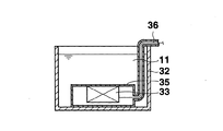
図3の超音波洗浄器は、投込振動子タイプと呼ばれており、洗浄槽32の内部に、水密容器35の内側面に超音波振動子33が固定された構成の超音波付与装置が配置された構成を有している。
The ultrasonic cleaner shown in FIG. 3 is called a throwing vibrator type, and an ultrasonic applicator having a configuration in which the
また、上記非特許文献1には、図1から図3に示す超音波洗浄器の他にも、洗浄槽の側面に超音波振動子が付設されたものなど、様々な構成の超音波洗浄器が記載されている。 In addition to the ultrasonic cleaners shown in FIGS. 1 to 3, the non-patent document 1 includes ultrasonic cleaners having various configurations such as an ultrasonic vibrator attached to the side surface of the cleaning tank. Is described.
超音波洗浄器には、小型のものを除いて、通常複数個の超音波振動子が用いられる。例えば、上記の洗浄槽タイプの超音波洗浄器の場合においては、その洗浄槽の底面に複数個の超音波振動子が固定される。このような構成の超音波洗浄器の場合、物品の洗浄ムラの発生を低減するためには、洗浄槽の底面に複数個の超音波振動子を高密度に配置して、洗浄槽の底面の全体をなるべく均一に超音波振動(上下方向に振動)させることが好ましい。ただし、一般には、超音波洗浄器の製造コストを考慮して、用いる超音波振動子の個数の上限が決定される。 For ultrasonic cleaners, except for small ones, a plurality of ultrasonic vibrators are usually used. For example, in the case of the above-described cleaning tank type ultrasonic cleaner, a plurality of ultrasonic vibrators are fixed to the bottom surface of the cleaning tank. In the case of an ultrasonic cleaner having such a configuration, in order to reduce the occurrence of uneven cleaning of articles, a plurality of ultrasonic vibrators are arranged at high density on the bottom surface of the cleaning tank, It is preferable to ultrasonically vibrate the whole as much as possible (vibrates in the vertical direction). However, in general, the upper limit of the number of ultrasonic transducers to be used is determined in consideration of the manufacturing cost of the ultrasonic cleaner.
複数個の超音波振動子を備える超音波洗浄器の場合、洗浄槽の底面の全体をなるべく均一に超音波振動させるために、各々の超音波振動子としては、底面との接触面積が大きい形状、すなわち横長の形状のもの(例、板状の圧電振動子)が従来は用いられている。 In the case of an ultrasonic cleaner equipped with a plurality of ultrasonic vibrators, each ultrasonic vibrator has a shape with a large contact area with the bottom surface in order to vibrate the entire bottom surface of the washing tank as uniformly as possible. That is, a horizontally long shape (eg, a plate-like piezoelectric vibrator) has been conventionally used.
特許文献1においては、磁器製の洗浄槽の底面に音響整合層を介して板状の超音波振動子が固定された構成の超音波洗浄器が開示され、洗浄槽を磁器から形成することによって、腐食性を示す薬液を用いた洗浄が実現できるとされている。 In patent document 1, the ultrasonic cleaner of the structure by which the plate-shaped ultrasonic vibrator was fixed to the bottom face of the washing tank made from porcelain via the acoustic matching layer was disclosed, and by forming the washing tank from porcelain It is said that cleaning using a chemical solution exhibiting corrosiveness can be realized.
特許文献2においては、洗浄槽の底面に、合成樹脂中に複数個の角柱状の圧電体を整列配置させ、その上下面を一対の電極で挟んだ構成の超音波振動子が固定された超音波洗浄器が開示され、上記角柱状の圧電体が板状の圧電体よりも電気機械変換効率が高く、この圧電体を備えた超音波振動子により1MHz程度以上の高い周波数の高エネルギーの超音波を洗浄槽内に発振できるため、サブミクロン単位の汚れを容易に洗浄できるとされている。 In Patent Document 2, an ultrasonic transducer having a structure in which a plurality of prismatic piezoelectric bodies are aligned in a synthetic resin and sandwiched between a pair of electrodes on a bottom surface of a cleaning tank is fixed. A sonic cleaner is disclosed, and the above-mentioned prismatic piezoelectric body has higher electromechanical conversion efficiency than a plate-like piezoelectric body, and an ultrasonic vibrator provided with this piezoelectric body has a high-frequency superhigh frequency of about 1 MHz or more. It is said that since the sound wave can be oscillated in the washing tank, the submicron dirt can be easily washed.
特許文献3には、母材樹脂中に高弾性繊維が整列配置された構成の音響振動制御材料が接合された圧電振動子が開示されている。音響振動制御材料の高弾性繊維は、その長さ方向に振動する音響振動の励起を抑え、そして繊維の長さ方向に直交する方向に振動する音響振動を伝達する。このため、圧電振動子の振動方向を、音響振動制御材料の高弾性繊維の長さ方向に直交する方向に制御できるとされている。
上記のように、複数個の超音波振動子あるいは特許文献3に記載の超音波振動子の複数個の振動部(各々の圧電体がある部分)により、洗浄槽の底面を有る程度は均一に超音波振動させることができるため、洗浄ムラの発生を低減することはできる。しかしながら、洗浄槽の底面は、その超音波振動子(あるいは振動部)が配置された部位は大きく振動するものの、超音波振動子が配置されていない部位は小さく振動する。すなわち洗浄槽の底面は波打つように不均一に振動し易い。本発明者の研究によると、特に、超音波振動子として横長の形状のもの(例、板状の圧電振動子)を用いると、これを縦方向に所定の周波数で超音波振動させた場合に、振動子が前記周波数に対応する高次の共振を生じて横方向にも振動し易いため、洗浄槽の底面を上下方向に均一に超音波振動させ難い。 As described above, a plurality of ultrasonic vibrators or a plurality of vibrating parts (parts where each piezoelectric body is provided) of the ultrasonic vibrator described in Patent Document 3 have a uniform degree of having a bottom surface of the cleaning tank. Since ultrasonic vibration can be performed, the occurrence of uneven cleaning can be reduced. However, the bottom surface of the cleaning tank vibrates greatly at the site where the ultrasonic transducer (or vibration unit) is disposed, but vibrates small at the site where the ultrasonic transducer is not disposed. That is, the bottom surface of the cleaning tank is likely to vibrate unevenly so as to wave. According to the research of the present inventor, in particular, when an ultrasonic vibrator having a horizontally long shape (eg, a plate-like piezoelectric vibrator) is used, the ultrasonic vibrator is ultrasonically vibrated at a predetermined frequency in the vertical direction. Since the vibrator generates high-order resonance corresponding to the frequency and easily vibrates in the lateral direction, it is difficult to uniformly ultrasonically vibrate the bottom surface of the cleaning tank in the vertical direction.
超音波洗浄器は、半導体素子作製用のウエハなどのように極めて均一に洗浄することが必要とされる物品の洗浄にも用いられるため、洗浄ムラの発生をさらに低減することが望ましい。 Since the ultrasonic cleaner is also used for cleaning an article that needs to be cleaned extremely uniformly, such as a wafer for manufacturing a semiconductor element, it is desirable to further reduce the occurrence of cleaning unevenness.
従って、本発明の目的は、洗浄ムラの発生を低減することのできる超音波洗浄器を提供することにある。 Accordingly, an object of the present invention is to provide an ultrasonic cleaner capable of reducing the occurrence of cleaning unevenness.
本発明は、洗浄槽の底面もしくは側面の外側表面に、バインダ樹脂及びこのバインダ樹脂中に上記表面に平行に整列配置された複数本の高弾性繊維からなる繊維強化樹脂板が固定され、そして上記繊維強化樹脂板の洗浄槽側とは逆側の表面に、縦長の柱状圧電体の表面の対象位置に一対の電極が付設されてなる柱状圧電振動子の複数個が、それぞれの頂面もしくは底面にて固定されていることを特徴とする超音波洗浄器にある。 In the present invention, a fiber reinforced resin plate composed of a binder resin and a plurality of highly elastic fibers arranged in parallel with the surface of the binder resin is fixed to the outer surface of the bottom surface or side surface of the cleaning tank, and the above A plurality of columnar piezoelectric vibrators in which a pair of electrodes are attached to a target position on the surface of a vertically long columnar piezoelectric body on the surface opposite to the cleaning tank side of the fiber reinforced resin plate are respectively the top surface or the bottom surface. It is in the ultrasonic cleaner characterized by being fixed by.
この本発明の超音波洗浄器の好ましい態様は、下記の通りである。
(1)柱状圧電体が角柱状の圧電体であって、その高さ方向の長さが、頂面及び底面を構成するいずれの辺の長さに対しても1.3倍以上(特に、2.0〜8.0倍)である。
(2)一対の電極が柱状圧電体の側面に付設されている。
Preferred embodiments of the ultrasonic cleaner of the present invention are as follows.
(1) The columnar piezoelectric body is a prismatic piezoelectric body, and the length in the height direction is 1.3 times or more with respect to the length of any side constituting the top surface and the bottom surface (in particular, 2.0 to 8.0 times).
(2) A pair of electrodes is attached to the side surface of the columnar piezoelectric body.
本発明はまた、洗浄槽の底面もしくは側面の内側表面に、バインダ樹脂及びこのバインダ樹脂中に上記表面に平行に整列配置された複数本の高弾性繊維からなる繊維強化樹脂板が固定され、そして上記洗浄槽の外側表面で、繊維強化樹脂板の固定領域に対応する領域に、縦長の柱状圧電体の表面の対象位置に一対の電極が付設されてなる柱状圧電振動子の複数個が、それぞれの頂面もしくは底面にて固定されていることを特徴とする超音波洗浄器にもある。 In the present invention, a fiber reinforced resin plate comprising a binder resin and a plurality of highly elastic fibers arranged in parallel to the surface in the binder resin is fixed to the inner surface of the bottom surface or side surface of the cleaning tank, and A plurality of columnar piezoelectric vibrators each having a pair of electrodes attached to target positions on the surface of a vertically long columnar piezoelectric body in a region corresponding to a fixed region of the fiber reinforced resin plate on the outer surface of the cleaning tank, There is also an ultrasonic cleaner characterized by being fixed at the top surface or bottom surface.
この本発明の超音波洗浄器の好ましい態様は、下記の通りである。
(1)柱状圧電体が角柱状の圧電体であって、その高さ方向の長さが、頂面及び底面を構成するいずれの辺の長さに対しても1.3倍以上(特に、2.0〜8.0倍)である。
(2)一対の電極が柱状圧電体の側面に付設されている。
Preferred embodiments of the ultrasonic cleaner of the present invention are as follows.
(1) The columnar piezoelectric body is a prismatic piezoelectric body, and the length in the height direction is 1.3 times or more with respect to the length of any side constituting the top surface and the bottom surface (in particular, 2.0 to 8.0 times).
(2) A pair of electrodes is attached to the side surface of the columnar piezoelectric body.
本発明はまた、金属板の一方の表面に、バインダ樹脂及びこのバインダ樹脂中に上記表面に平行に整列配置された複数本の高弾性繊維からなる繊維強化樹脂板が固定され、そして上記繊維強化樹脂板の金属板側とは逆側の表面に、縦長の柱状圧電体の表面の対象位置に一対の電極が付設されてなる柱状圧電振動子の複数個が、それぞれの頂面もしくは底面にて固定されていることを特徴とする振動板にもある。 In the present invention, a fiber reinforced resin plate composed of a binder resin and a plurality of highly elastic fibers arranged in parallel to the surface of the binder resin is fixed to one surface of the metal plate, and the fiber reinforced A plurality of columnar piezoelectric vibrators in which a pair of electrodes are attached to the target position on the surface of a vertically long columnar piezoelectric body on the surface opposite to the metal plate side of the resin plate, on each top surface or bottom surface. There is also a diaphragm characterized by being fixed.
この本発明の振動板の好ましい態様は、下記の通りである。
(1)柱状圧電体が角柱状の圧電体であって、その高さ方向の長さが、頂面及び底面を構成するいずれの辺の長さに対しても1.3倍以上(特に、2.0〜8.0倍)である。
(2)一対の電極が柱状圧電体の側面に付設されている。
(3)洗浄槽の内部に設置して用いるためのものである。
Preferred embodiments of the diaphragm of the present invention are as follows.
(1) The columnar piezoelectric body is a prismatic piezoelectric body, and the length in the height direction is 1.3 times or more with respect to the length of any side constituting the top surface and the bottom surface (in particular, 2.0 to 8.0 times).
(2) A pair of electrodes is attached to the side surface of the columnar piezoelectric body.
(3) For installation and use inside the cleaning tank.
本発明はまた、金属板の一方の表面に、バインダ樹脂及び該バインダ樹脂中に上記表面に平行に整列配置された複数本の高弾性繊維からなる繊維強化樹脂板が固定され、そして金属板の他方の表面で、繊維強化樹脂板の固定領域に対応する領域に、縦長の柱状圧電体の表面の対象位置に一対の電極が付設されてなる柱状圧電振動子の複数個が、それぞれの頂面もしくは底面にて固定されていることを特徴とする振動板にもある。 In the present invention, a fiber reinforced resin plate composed of a binder resin and a plurality of highly elastic fibers arranged in parallel to the surface of the binder resin is fixed to one surface of the metal plate. On the other surface, a plurality of columnar piezoelectric vibrators each having a pair of electrodes attached to a target position on the surface of a vertically long columnar piezoelectric body in a region corresponding to the fixed region of the fiber reinforced resin plate, Alternatively, the diaphragm is characterized by being fixed at the bottom surface.
(1)柱状圧電体が角柱状の圧電体であって、その高さ方向の長さが、頂面及び底面を構成するいずれの辺の長さに対しても1.3倍以上(特に、2.0〜8.0倍)である。
(2)一対の電極が柱状圧電体の側面に付設されている。
(3)洗浄槽の内部に設置して用いるためのものである。
(1) The columnar piezoelectric body is a prismatic piezoelectric body, and the length in the height direction is 1.3 times or more with respect to the length of any side constituting the top surface and the bottom surface (in particular, 2.0 to 8.0 times).
(2) A pair of electrodes is attached to the side surface of the columnar piezoelectric body.
(3) For installation and use inside the cleaning tank.
本発明の超音波洗浄器は、洗浄槽の底面もしくは側面の外側表面に、バインダ樹脂及びこのバインダ樹脂中に上記表面に平行に整列配置された複数本の高弾性繊維からなる繊維強化樹脂板が固定され、そして上記繊維強化樹脂板の洗浄槽側とは逆側の表面に、縦長の柱状圧電体の表面の対象位置に一対の電極が付設されてなる柱状圧電振動子の複数個が、それぞれの頂面もしくは底面にて固定されていることを特徴とする。 In the ultrasonic cleaner of the present invention, a fiber reinforced resin plate made of a binder resin and a plurality of highly elastic fibers arranged in parallel in the binder resin in parallel with the surface is provided on the outer surface of the bottom surface or side surface of the cleaning tank. A plurality of columnar piezoelectric vibrators each having a pair of electrodes attached to a target position on the surface of a vertically long columnar piezoelectric body on the surface opposite to the cleaning tank side of the fiber reinforced resin plate, It is fixed at the top surface or the bottom surface of.
本発明の超音波洗浄器は、その各々の柱状圧電振動子の頂面を高さ方向に均一に超音波振動させ、そして繊維強化樹脂板により前記超音波振動が付与された洗浄槽の底面の全体を上下方向に均一に超音波振動させることができるため、洗浄ムラの発生が低減される。本発明の超音波洗浄器においては、その柱状圧電振動子に付与した電気エネルギーの大部分が洗浄槽の底面を上下に超音波振動させるために用いられる。従って、本発明の超音波洗浄器は、柱状圧電振動子に付与する電気エネルギーが同じである場合には、従来の超音波洗浄器よりも大きな超音波振動を洗浄液に付与することができるため、強い洗浄力を示す。 The ultrasonic cleaner of the present invention is configured to uniformly ultrasonically vibrate the top surface of each of the columnar piezoelectric vibrators in the height direction, and to apply the ultrasonic vibration to the bottom surface of the cleaning tank provided with a fiber reinforced resin plate. Since the whole can be ultrasonically vibrated in the vertical direction, the occurrence of uneven cleaning is reduced. In the ultrasonic cleaner of the present invention, most of the electric energy applied to the columnar piezoelectric vibrator is used for ultrasonically vibrating the bottom surface of the cleaning tank up and down. Therefore, the ultrasonic cleaner of the present invention can apply a larger ultrasonic vibration to the cleaning liquid than the conventional ultrasonic cleaner when the electric energy applied to the columnar piezoelectric vibrator is the same. Shows strong detergency.
まず、本発明の超音波洗浄器を添付の図面を用いて説明する。図4は、本発明の超音波洗浄器の構成例を示す断面図であり、図5及び図6は、図4の超音波洗浄器の柱状圧電振動子及び繊維強化樹脂板を、それぞれ下側及び右側から見た図であり、そして図7は、図4の超音波洗浄器が備える柱状圧電振動子の構成を示す斜視図である。 First, the ultrasonic cleaner of the present invention will be described with reference to the accompanying drawings. FIG. 4 is a cross-sectional view showing a configuration example of the ultrasonic cleaner of the present invention. FIGS. 5 and 6 show the columnar piezoelectric vibrator and the fiber reinforced resin plate of the ultrasonic cleaner of FIG. FIG. 7 is a perspective view showing a configuration of a columnar piezoelectric vibrator provided in the ultrasonic cleaner of FIG. 4.
図4から図7に示す超音波洗浄器40は、洗浄槽12の底面の外側表面に、バインダ樹脂及びこのバインダ樹脂中に上記表面に平行に整列配置された複数本の高弾性繊維(図示は略する)からなる繊維強化樹脂板44が固定され、そして繊維強化樹脂板44の洗浄槽12の側とは逆側の表面に、縦長の柱状圧電体46の表面の対象位置に一対の電極47a、47bが付設されてなる柱状圧電振動子43の複数個が、それぞれの頂面にて固定されていることを特徴とする。
The
洗浄槽12は、通常、ステンレススチールなどの金属材料から形成される。洗浄液として酸性溶液もしくはアルカリ性溶液のような腐食性の高い液体を用いる場合には、洗浄槽を、樹脂(例:塩化ビニル樹脂、フッ素樹脂)、ガラス、もしくはセラミックスなどから形成することが好ましい。洗浄槽12を金属材料から形成する場合には、洗浄槽12と繊維強化樹脂板44とが電気的に導通することを防止するために、洗浄槽12に絶縁材を介して繊維強化樹脂板44を付設しても良い。絶縁材の例としては、樹脂材料やガラスエポキシ材が挙げられる。絶縁材の厚みは、1mm以下、好ましくは0.5mm以下であることが好ましい。
The
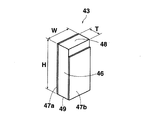
図7に示すように、柱状圧電振動子43のそれぞれは、縦長の柱状圧電体46の表面の対象位置に一対の電極47a、47bが付設された構成を有している。柱状圧電体46は、例えば、ジルコン酸チタン酸鉛系の圧電セラミックから形成され、その幅(W)が4mmに、厚み(T)が2mmに、そして高さ(H)が8mmに設定されている。圧電体46は、例えば、その厚み方向に分極される。一対の電極47a、47bのそれぞれは、例えば、厚みが5μm程度のリン青銅や銀などの金属材料から形成された薄膜が用いられる。
As shown in FIG. 7, each of the columnar
複数個の柱状圧電振動子43は、例えば、エポキシ樹脂などにより繊維強化樹脂板44の表面に固定される。図4から図6に示すように、繊維強化樹脂板44の表面にフライスなどを用いて溝45を形成し、各々の柱状圧電振動子43を溝45に嵌め合わせるようにすると、振動子43の固定が容易となる。図4から図7に示す複数個の圧電振動子43は、間隔L1 及びL2 が、それぞれ8.67mm及び8.44mmとなるように繊維強化樹脂板44の表面に固定されている。
The plurality of columnar
洗浄槽12の底面の外側表面に固定された繊維強化樹脂板44は、バインダ樹脂及びこのバインダ樹脂中に上記表面に平行に整列配置された複数本の高弾性繊維(図示は略する)から構成されている。図4の超音波洗浄器40の繊維強化樹脂板44には、そのバインダ樹脂としてエポキシ樹脂が、そして高弾性繊維として炭素繊維が用いられている。繊維強化樹脂板44は、炭素繊維を用いるために導電性を示す。このため、繊維強化樹脂板44に固定された複数個の柱状圧電振動子43は、それぞれその電極47aが繊維強化樹脂板44と電気的に接続されることとなる。従って、複数個の柱状圧電振動子43を超音波振動させるためには、繊維強化樹脂板44と各々の柱状圧電振動子43の電極47bとの間に交流電圧を印加すれば良い。
The fiber reinforced
そして柱状圧電振動子43を高さ方向に超音波振動させるためには、その一対の電極47a、47bの間に、柱状圧電体46の高さ方向の長さにより定まる共振周波数に対応する周波数の交流電圧を印加する。柱状圧電体46は縦長の形状であるため、その高さ方向の長さは、頂面48及び底面49を構成するいずれの辺の長さよりも長い。このため柱状圧電体46の幅方向及び厚み方向のそれぞれの長さにより定まる共振周波数は、高さ方向の長さにより定まる共振周波数よりも高い。従って、柱状圧電振動子43を高さ方向に超音波振動させた場合には、柱状圧電体46はその幅及び厚みのいずれの方向においても共振しない。従って、柱状圧電振動子43の頂面の全体が、高さ方向に均一に超音波振動する。
In order to ultrasonically vibrate the columnar
柱状圧電振動子43の幅方向及び厚み方向のそれぞれにおける共振の発生を抑制するために、柱状圧電体46の高さ方向の長さは、圧電体46の頂面48及び底面49を構成するいずれの辺の長さに対しても1.3倍以上であることが好ましく、2.0〜8.0倍の範囲にあることがさらに好ましい。
In order to suppress the occurrence of resonance in each of the width direction and the thickness direction of the columnar
このように縦長の柱状圧電振動子43の頂面は均一に超音波振動するものの、この柱状圧電振動子43の複数個を洗浄槽12の底面に直接固定しただけでは、上記のように洗浄槽12の底面が波打つように不均一に振動し易い。図4の超音波洗浄器40の底面に固定された繊維強化樹脂板44は、この洗浄槽12の底面の不均一な振動の発生を抑制して、洗浄槽12の底面を上下方向に均一に振動させるために用いられている。
As described above, although the top surface of the vertically long columnar
繊維強化樹脂板44が備えられた高弾性繊維は、その長さ方向に伸縮し難い。このような繊維強化樹脂板44を洗浄槽12の底面の外側表面に固定すると、底面の波打つような不均一な振動の発生が抑制される。これは、洗浄槽12の底面が波打つように振動するためには、底面に固定された繊維強化樹脂板44の高弾性繊維が直線形から波形に変形するための、すなわち高弾性繊維をその長さ方向に伸ばすための大きなエネルギーが必要とされるためである。このため、複数個の柱状圧電振動子43により発生した超音波振動によって、洗浄槽12の底面の全体を上下方向に均一に超音波振動させることができる。
The highly elastic fiber provided with the fiber reinforced
このように、図4の超音波洗浄器40は、その各々の柱状圧電振動子43の頂面を高さ方向に均一に超音波振動させ、そして繊維強化樹脂板44により前記超音波振動が付与された洗浄槽12の底面の全体を上下方向に均一に超音波振動させることができるため、洗浄ムラの発生が低減される。また、超音波洗浄器40の柱状圧電振動子43に付与した電気エネルギーの大部分は、洗浄槽12の底面を上下に超音波振動させるために用いられる。従って、図4の超音波洗浄器40は、圧電振動子に付与する電気エネルギーが同じである場合には、従来の超音波洗浄器よりも大きな超音波振動を洗浄液に付与することができるため、強い洗浄力を示す。
As described above, the
繊維強化樹脂板44の複数本の高弾性繊維は、洗浄槽12の底面の外側表面に平行に整列配置されていれば、その配置に特に制限はない。複数本の高弾性繊維は、洗浄槽12の底面の外側表面と平行な一方向に整列配置されていてもよいし、前記表面と平行で、かつ互いに直交する二方向に整列配置されていてもよい。
The plurality of highly elastic fibers of the fiber reinforced
バインダ樹脂の例としては、エポキシ樹脂、ポリアミド樹脂、ポリイミド樹脂、PEEK(ポリエーテルエーテルケトン)樹脂、フェノール樹脂、不飽和ポリエステル樹脂、ポリカーボネート樹脂、およびポリアミドイミド樹脂などが挙げられる。 Examples of the binder resin include epoxy resin, polyamide resin, polyimide resin, PEEK (polyether ether ketone) resin, phenol resin, unsaturated polyester resin, polycarbonate resin, and polyamideimide resin.
高弾性繊維の例としては、炭素繊維、炭化ケイ素繊維、ポリアミド繊維、およびアラミド繊維などが挙げられる。 Examples of the highly elastic fiber include carbon fiber, silicon carbide fiber, polyamide fiber, and aramid fiber.
洗浄槽12の底面を均一超音波振動させるためには、繊維強化樹脂板44の洗浄槽側の表面の面積を、なるべく洗浄槽の底面と一致する程度まで大きくすることが好ましい。また、洗浄対象の物品が大きい場合には洗浄槽は大型となり、その底面の面積も大きくなる。大型の洗浄槽の底面に繊維強化樹脂板を付設する場合には、洗浄槽の底面に沿って複数個の繊維強化樹脂板を付設しても良い。複数個の繊維強化樹脂板は、それらが互いに間隔を空けた状態で付設されていても良い。
In order to uniformly ultrasonically vibrate the bottom surface of the
繊維強化樹脂板44の厚みは、柱状圧電振動子43が発生する超音波振動の洗浄槽12の底面における反射量を低減するために、超音波振動の波長の1/4の厚みであることが好ましい。繊維強化樹脂板44の厚みは、繊維強化樹脂板中における超音波の減衰が大きい場合には、超音波振動の波長の1/4の厚みよりもさらに薄くすることが好ましい。
The thickness of the fiber reinforced
次に、図4の超音波洗浄器40を用いた物品の洗浄方法について説明する。まず、超音波洗浄器40の洗浄槽12に、例えば、水などの洗浄液11を入れる。次に、洗浄液11に洗浄対象の物品(図示は略する)を浸し、そして複数個の柱状圧電振動子43により洗浄液11に超音波振動を付与することにより、物品が超音波洗浄される。上記のように本発明の超音波洗浄器40を用いることにより、物品の洗浄ムラの発生が低減される。
Next, a method for cleaning an article using the
洗浄に用いる超音波振動の周波数は、50乃至500kHzの範囲にあることが好ましい。柱状圧電振動子43が備える柱状圧電体46の高さは、通常、前記の超音波振動の周波数において共振するように、40mm乃至4mmの範囲に設定される。このような周波数の超音波振動を用いることにより、物品表面の損傷を抑え、かつ十分に強い洗浄力で物品を超音波洗浄することができる。
The frequency of ultrasonic vibration used for cleaning is preferably in the range of 50 to 500 kHz. The height of the columnar
本発明の超音波洗浄器に用いられる縦長の柱状圧電体としては、円柱状の圧電体を用いることもできる。円柱状の圧電体の高さ方向の長さは、頂面及び底面のいずれの直径に対しても1.3倍以上(特に、2.0〜8.0倍)であることが好ましい。円柱状圧電体を用いる場合には、一対の電極はその頂面と底面に付設されていることが好ましい。なお、従来の超音波洗浄器には、円盤状の圧電振動子を一対の円柱状金属ブロックで挟み、これらをボルト締めした構成の縦長の円柱状ランジュバン振動子が用いられる場合もあるが、このランジュバン振動子は、一般に10〜50kHzの低い周波数の超音波振動を発生させるために用いられるものである。仮にランジュバン振動子を用いて、縦長の円柱状の形状を維持したまま、周波数が100kHzの超音波振動を発生させる場合にはその直径を1cm以下に、さらに周波数が500kHzの超音波振動を発生される場合には、その直径を4mm以下にする必要があり、その製造が極めて困難である。 As the vertically long columnar piezoelectric body used in the ultrasonic cleaner of the present invention, a cylindrical piezoelectric body can also be used. The length of the cylindrical piezoelectric body in the height direction is preferably 1.3 times or more (particularly 2.0 to 8.0 times) for both the top and bottom diameters. In the case of using a cylindrical piezoelectric body, the pair of electrodes are preferably attached to the top and bottom surfaces. In addition, in a conventional ultrasonic cleaner, a vertically long cylindrical Langevin vibrator having a configuration in which a disk-shaped piezoelectric vibrator is sandwiched between a pair of cylindrical metal blocks and these are bolted may be used. The Langevin vibrator is generally used for generating ultrasonic vibration of a low frequency of 10 to 50 kHz. If an ultrasonic vibration having a frequency of 100 kHz is generated using a Langevin vibrator while maintaining a vertically long cylindrical shape, the diameter is reduced to 1 cm or less and an ultrasonic vibration having a frequency of 500 kHz is further generated. In this case, the diameter needs to be 4 mm or less, and its manufacture is extremely difficult.
本発明の超音波洗浄器に用いられる縦長の柱状圧電体としては、図7に示すような角柱状の圧電体を用いることが好ましく、さらにその側面に一対の電極が付設されていることが好ましい。一対の電極が角柱状圧電体の頂面と底面に付設されていると、圧電体の高さ方向の長さが大きくなるほど圧電体に加わる電界強度が小さくなり、圧電体を超音波振動させるために大きな交流電圧の印加が必要となるからである。柱状圧電振動子を、角柱状圧電体の側面に一対の電極が付設された構成にすると、用いる超音波振動の周波数が低い場合、すなわち圧電体の高さ方向の長さが大きい場合であっても、角柱状圧電体に大きな強度の電界を印加できるため、これを高さ方向に大きく振動させることができる。 As the vertically long columnar piezoelectric body used in the ultrasonic cleaner of the present invention, a prismatic piezoelectric body as shown in FIG. 7 is preferably used, and a pair of electrodes are preferably provided on the side surfaces thereof. . When a pair of electrodes are attached to the top and bottom surfaces of a prismatic piezoelectric body, the electric field strength applied to the piezoelectric body decreases as the length in the height direction of the piezoelectric body increases, and the piezoelectric body is subjected to ultrasonic vibration. This is because it is necessary to apply a large alternating voltage. When the columnar piezoelectric vibrator has a configuration in which a pair of electrodes are attached to the side surface of the prismatic piezoelectric body, the ultrasonic vibration frequency used is low, that is, the length of the piezoelectric body in the height direction is large. However, since an electric field having a large strength can be applied to the prismatic piezoelectric body, it can be vibrated greatly in the height direction.
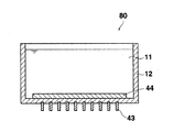
図8は、本発明の超音波洗浄器の別の構成例を示す断面図である。図8の超音波洗浄器80は、洗浄槽12の底面の内側表面に、バインダ樹脂及びこのバインダ樹脂中に上記表面に平行に整列配置された複数本の高弾性繊維からなる繊維強化樹脂板44が固定され、そして上記洗浄槽12の外側表面で、繊維強化樹脂板44の固定領域に対応する領域に、縦長の柱状圧電体の表面の対象位置に一対の電極が付設されてなる柱状圧電振動子43の複数個が、それぞれの頂面にて固定された構成を有している。
FIG. 8 is a cross-sectional view showing another configuration example of the ultrasonic cleaning device of the present invention. The
図8の超音波洗浄器80の構成は、繊維強化樹脂板44が洗浄槽12の底面の内側表面に付設されていること以外は、図4の超音波洗浄器40と同様である。繊維強化樹脂板44が洗浄槽の内側に付設されていても、洗浄槽の底面の不均一な振動の発生を低減することができる。このため図8の超音波洗浄器を用いて物品を洗浄することにより、物品表面の洗浄ムラの発生を低減することができる。
The configuration of the
図9は、本発明の超音波洗浄器のさらに別の構成例を示す断面図である。図9の超音波洗浄器90の構成は、洗浄槽22の底板として脱着可能とされた金属板95が用いられていること以外は、図4の超音波洗浄器40と同様である。
FIG. 9 is a cross-sectional view showing still another configuration example of the ultrasonic cleaning device of the present invention. The configuration of the
金属板95、繊維強化樹脂板44、そして複数個の超音波振動子43により本発明の振動板が構成されている。図9に示す振動板は、金属板95の一方の表面に、バインダ樹脂及びこのバインダ樹脂中に上記表面に平行に整列配置された複数本の高弾性繊維からなる繊維強化樹脂板44が固定され、そして上記繊維強化樹脂板44の金属板95の側とは逆側の表面に、縦長の柱状圧電体の表面の対象位置に一対の電極が付設されてなる柱状圧電振動子43の複数個が、それぞれの頂面にて固定された構成を有している。
The
本発明の振動板は、洗浄槽22から脱着可能であるため、金属板95が腐食したり、振動板が破損などした場合であっても、別の振動板と容易に交換することができる。
Since the diaphragm of the present invention can be detached from the
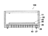
図10は、本発明の超音波洗浄器のさらに別の構成例を示す断面図である。図10の超音波洗浄器100の構成は、洗浄槽22の底板として脱着可能とされた金属板95が用いられていること以外は、図8の超音波洗浄器80と同様である。
FIG. 10 is a cross-sectional view showing still another configuration example of the ultrasonic cleaner according to the present invention. The configuration of the
金属板95、繊維強化樹脂板44、そして複数個の超音波振動子43により本発明の振動板が構成されている。図10に示す振動板は、金属板95の一方の表面に、バインダ樹脂及び該バインダ樹脂中に上記表面に平行に整列配置された複数本の高弾性繊維からなる繊維強化樹脂板44が固定され、そして金属板95の他方の表面で、繊維強化樹脂板44の固定領域に対応する領域に、縦長の柱状圧電体の表面の対象位置に一対の電極が付設されてなる柱状圧電振動子43の複数個が、それぞれの頂面にて固定された構成を有している。
The
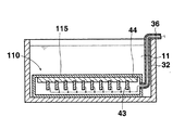
図11は、本発明の振動板の別の構成例と、その使用の態様を示す断面図である。図11に示す振動板は、金属板115の一方の表面に、バインダ樹脂及びこのバインダ樹脂中に上記表面に平行に整列配置された複数本の高弾性繊維からなる繊維強化樹脂板44が固定され、そして上記繊維強化樹脂板44の金属板115の側とは逆側の表面に、縦長の柱状圧電体の表面の対象位置に一対の電極が付設されてなる柱状圧電振動子43の複数個が、それぞれの頂面にて固定された構成を有している。
FIG. 11 is a cross-sectional view showing another configuration example of the diaphragm of the present invention and a mode of use thereof. In the diaphragm shown in FIG. 11, a fiber reinforced
図11に示す振動板は、洗浄槽32の内部に設置して用いるためのものである。このため、振動板の複数個の柱状圧電振動子43が、水などの導電性を示す液体を洗浄液11として用いた場合に互いに電気的に短絡することを防止する必要がある。このため、振動板の金属板115は、その周端部が延長されて複数個の柱状圧電振動子43を収容する箱形とされている。なお、柱状圧電振動子43のそれぞれに接続する電気配線36は、箱に接続されたチューブの内部を通って洗浄槽32の外に引き出されている。なお、金属板115を箱形にする代わりに、例えば、振動板の複数個の柱状圧電振動子43を絶縁性の樹脂により覆うこともできる。
The diaphragm shown in FIG. 11 is used for installation inside the
図12は、本発明の振動板のさらに別の構成例と、その使用の態様を示す断面図である。図12に示す振動板は、金属板115の一方の表面に、バインダ樹脂及び該バインダ樹脂中に上記表面に平行に整列配置された複数本の高弾性繊維からなる繊維強化樹脂板44が固定され、そして金属板115の他方の表面で、繊維強化樹脂板44の固定領域に対応する領域に、縦長の柱状圧電体の表面の対象位置に一対の電極が付設されてなる柱状圧電振動子43の複数個が、それぞれの頂面にて固定された構成を有している。
FIG. 12 is a cross-sectional view showing still another configuration example of the diaphragm of the present invention and a mode of use thereof. In the diaphragm shown in FIG. 12, a fiber reinforced
図12の振動板もまた、図11の振動板と同様に洗浄槽32の内部に設置して用いるためのものである。
The diaphragm shown in FIG. 12 is also used by being installed inside the
11 洗浄液
12、22、32 洗浄槽
13、23、33 超音波振動子
25 底板
26 パッキン
27 ボルト
28 ナット
35 水密容器
36 電気配線
40、80、90、100 超音波洗浄器
43 柱状圧電振動子
44 繊維強化樹脂板
45 溝
46 柱状圧電体
47a、47b 電極
48 柱状圧電体の頂面
49 柱状圧電体の底面
95、115 金属板
W 柱状圧電体の幅
T 柱状圧電体の厚み
H 柱状圧電体の高さ
DESCRIPTION OF
Claims (14)
The diaphragm according to any one of claims 11 to 13, which is used by being installed inside a cleaning tank.
Priority Applications (1)
| Application Number | Priority Date | Filing Date | Title |
|---|---|---|---|
| JP2004117112A JP2005296813A (en) | 2004-04-12 | 2004-04-12 | Ultrasonic cleaner |
Applications Claiming Priority (1)
| Application Number | Priority Date | Filing Date | Title |
|---|---|---|---|
| JP2004117112A JP2005296813A (en) | 2004-04-12 | 2004-04-12 | Ultrasonic cleaner |
Publications (2)
| Publication Number | Publication Date |
|---|---|
| JP2005296813A true JP2005296813A (en) | 2005-10-27 |
| JP2005296813A5 JP2005296813A5 (en) | 2007-05-31 |
Family
ID=35329007
Family Applications (1)
| Application Number | Title | Priority Date | Filing Date |
|---|---|---|---|
| JP2004117112A Pending JP2005296813A (en) | 2004-04-12 | 2004-04-12 | Ultrasonic cleaner |
Country Status (1)
| Country | Link |
|---|---|
| JP (1) | JP2005296813A (en) |
Cited By (3)
| Publication number | Priority date | Publication date | Assignee | Title |
|---|---|---|---|---|
| JP2008068221A (en) * | 2006-09-15 | 2008-03-27 | Pre-Tech Co Ltd | Ultrasonic cleaning device |
| CN103506348A (en) * | 2013-03-26 | 2014-01-15 | 新能(张家港)能源有限公司 | Cleaning device for dimethyl ether sampling device |
| CN113663980A (en) * | 2021-08-20 | 2021-11-19 | 陕西师范大学 | Ultrasonic transducer, ultrasonic cleaning device and cleaning method capable of vibrating in multiple directions |
-
2004
- 2004-04-12 JP JP2004117112A patent/JP2005296813A/en active Pending
Cited By (3)
| Publication number | Priority date | Publication date | Assignee | Title |
|---|---|---|---|---|
| JP2008068221A (en) * | 2006-09-15 | 2008-03-27 | Pre-Tech Co Ltd | Ultrasonic cleaning device |
| CN103506348A (en) * | 2013-03-26 | 2014-01-15 | 新能(张家港)能源有限公司 | Cleaning device for dimethyl ether sampling device |
| CN113663980A (en) * | 2021-08-20 | 2021-11-19 | 陕西师范大学 | Ultrasonic transducer, ultrasonic cleaning device and cleaning method capable of vibrating in multiple directions |
Similar Documents
| Publication | Publication Date | Title |
|---|---|---|
| US8279712B2 (en) | Composite transducer apparatus and system for processing a substrate and method of constructing the same | |
| US9610617B2 (en) | Megasonic multifrequency apparatus with matched transducer | |
| US20070283985A1 (en) | Ultrasonic Processing Method and Apparatus with Multiple Frequency Transducers | |
| US9987666B2 (en) | Composite transducer apparatus and system for processing a substrate and method of constructing the same | |
| JP6802290B2 (en) | Ultrasonic oscillator and ultrasonic cleaning device using ultrasonic oscillator | |
| US20130019893A1 (en) | Ultrasonic cleaning method and apparatus | |
| JP2005296813A (en) | Ultrasonic cleaner | |
| JP2009125645A (en) | Ultrasonic washing device and ultrasonic washing method | |
| JP3839154B2 (en) | Ultrasonic vibration generator and ultrasonic cleaning device | |
| JP2007301538A (en) | Ultrasonic cleaner | |
| JP2004130248A (en) | Ultrasonic cleaner, vibration plate for ultrasonic cleaner, and ultrasonic wave application apparatus for ultrasonic cleaner | |
| JP2002126668A (en) | Ultrasonic cleaning apparatus | |
| US20130118536A1 (en) | Ultrasonic precision cleaning apparatus | |
| JPWO2006095738A1 (en) | Ultrasonic cleaner | |
| WO2023181309A1 (en) | Vibrator unit and ultrasonic vacuum washing machine | |
| KR200171544Y1 (en) | Piezoelectric ceramic transducer | |
| KR100986586B1 (en) | The ultrasonic oscillator | |
| US10327736B1 (en) | Ultrasound transducer arrays and associated systems and methods | |
| JP2007237157A (en) | Ultrasonic washing apparatus | |
| JP2009082900A (en) | Ultrasonic cleaning apparatus and ultrasonic cleaning method | |
| JP2006150329A (en) | Ultrasonic vibration table | |
| JP2005334984A (en) | Vibrating table |
Legal Events
| Date | Code | Title | Description |
|---|---|---|---|
| A521 | Written amendment |
Free format text: JAPANESE INTERMEDIATE CODE: A523 Effective date: 20070404 |
|
| A621 | Written request for application examination |
Free format text: JAPANESE INTERMEDIATE CODE: A621 Effective date: 20070404 |
|
| A977 | Report on retrieval |
Free format text: JAPANESE INTERMEDIATE CODE: A971007 Effective date: 20090602 |
|
| A131 | Notification of reasons for refusal |
Free format text: JAPANESE INTERMEDIATE CODE: A131 Effective date: 20090901 |
|
| A02 | Decision of refusal |
Effective date: 20100105 Free format text: JAPANESE INTERMEDIATE CODE: A02 |


