JP2005296795A - Crusher - Google Patents
Crusher Download PDFInfo
- Publication number
- JP2005296795A JP2005296795A JP2004116615A JP2004116615A JP2005296795A JP 2005296795 A JP2005296795 A JP 2005296795A JP 2004116615 A JP2004116615 A JP 2004116615A JP 2004116615 A JP2004116615 A JP 2004116615A JP 2005296795 A JP2005296795 A JP 2005296795A
- Authority
- JP
- Japan
- Prior art keywords
- crushing
- rotor
- fixing plate
- fixed
- plate
- Prior art date
- Legal status (The legal status is an assumption and is not a legal conclusion. Google has not performed a legal analysis and makes no representation as to the accuracy of the status listed.)
- Granted
Links
- 238000012545 processing Methods 0.000 claims abstract description 29
- 230000002093 peripheral effect Effects 0.000 claims abstract description 10
- 239000000463 material Substances 0.000 claims description 31
- 238000003825 pressing Methods 0.000 claims description 4
- 238000007599 discharging Methods 0.000 claims description 2
- 238000005520 cutting process Methods 0.000 description 7
- 229910000831 Steel Inorganic materials 0.000 description 4
- 239000010959 steel Substances 0.000 description 4
- 238000000034 method Methods 0.000 description 3
- 238000005452 bending Methods 0.000 description 2
- 238000010586 diagram Methods 0.000 description 2
- 238000003754 machining Methods 0.000 description 2
- 229910052751 metal Inorganic materials 0.000 description 2
- 239000002184 metal Substances 0.000 description 2
- 238000012986 modification Methods 0.000 description 2
- 230000004048 modification Effects 0.000 description 2
- 230000008569 process Effects 0.000 description 2
- 230000009467 reduction Effects 0.000 description 2
- 230000035939 shock Effects 0.000 description 2
- 238000003860 storage Methods 0.000 description 2
- 229910052782 aluminium Inorganic materials 0.000 description 1
- XAGFODPZIPBFFR-UHFFFAOYSA-N aluminium Chemical compound [Al] XAGFODPZIPBFFR-UHFFFAOYSA-N 0.000 description 1
- 238000013459 approach Methods 0.000 description 1
- 230000008901 benefit Effects 0.000 description 1
- 230000007547 defect Effects 0.000 description 1
- 238000005553 drilling Methods 0.000 description 1
- 239000011521 glass Substances 0.000 description 1
- 238000012423 maintenance Methods 0.000 description 1
- 238000004519 manufacturing process Methods 0.000 description 1
- 238000004080 punching Methods 0.000 description 1
- 238000005096 rolling process Methods 0.000 description 1
- 239000007787 solid Substances 0.000 description 1
- 239000000126 substance Substances 0.000 description 1
Images


Landscapes
- Crushing And Pulverization Processes (AREA)
Abstract
【課題】 異物を適切に排出して、刃の破損のおそれを著しく減じることができ、かつ、破砕効率を向上する。
【解決手段】 破砕処理装置10は、外周面に、回転方向に複数の破砕刃を設けた破砕ロータ34と、破砕ロータ34の外側に位置し、破砕刃と協働して処理物を破砕する複数の孔を有する固定破砕部材と、破砕ロータの軸と連結され、前記破砕ロータを正転/逆転にて回転駆動するモータと、当該モータを駆動および制御する駆動手段とを備える。固定破砕部材は、破砕ロータ34の逆転方向の側に、その軸方向に延びるとともに、複数の孔が形成された固定破砕板30と、正転方向の側に、軸方向に延びる誘導板31とを有する。破砕ロータと固定破砕板との距離は、破砕ロータと誘導板との間の距離よりも十分に小さい。
【選択図】 図3
PROBLEM TO BE SOLVED: To appropriately discharge foreign matters, remarkably reduce the risk of blade breakage, and improve crushing efficiency.
A crushing processing apparatus 10 has a crushing rotor 34 provided with a plurality of crushing blades in the rotation direction on an outer peripheral surface, and is positioned outside the crushing rotor 34 to crush a processed product in cooperation with the crushing blades. A fixed crushing member having a plurality of holes, a motor connected to the shaft of the crushing rotor, and rotationally driving the crushing rotor by forward / reverse rotation, and drive means for driving and controlling the motor are provided. The fixed crushing member extends in the axial direction on the side of the crushing rotor 34 in the reverse direction, and has a fixed crushing plate 30 formed with a plurality of holes, and a guide plate 31 extending in the axial direction on the side of the normal rotation direction. Have The distance between the crushing rotor and the fixed crushing plate is sufficiently smaller than the distance between the crushing rotor and the guide plate.
[Selection] Figure 3
Description
本発明は、機械加工などにより発生した切粉や、種々の廃棄物などを短時間で破砕処理する破砕処理装置に関する。 The present invention relates to a crushing apparatus that crushes chips generated by machining or the like, various wastes, and the like in a short time.
従来、機械加工などにより多量に発生した切粉などの破砕対象物を、切断して減容処理する破砕処理装置が知られている。このような破砕処理装置においては、回転筒体にその軸線から半径方向に螺旋状、或いは、所定間隔で形成された回転刃と、ケーシングに、上記回転刃と対向するように配置された固定刃とにより、切粉などの破砕対象物を切断している。
しかしながら、上記従来の破砕処理装置においては、先端が鋭利な回転刃および固定刃が、回転筒体の回転により接近したときに、その隙間に入った破砕対象物を切断している。したがって、切粉など破砕対象物切断時に、ワークやピットなどの異物が混入するなど過負荷により、回転刃や固定刃が欠損ないし破損する場合がある。刃の欠損は、切断力の低下を招くため、刃の交換が必要となる。 However, in the conventional crushing apparatus described above, when the rotary blade and the fixed blade with sharp ends approach each other due to the rotation of the rotary cylinder, the crushing object that has entered the gap is cut. Therefore, when cutting an object to be crushed such as chips, foreign objects such as workpieces and pits may be mixed, and the rotary blade and fixed blade may be damaged or broken. Since a blade defect causes a reduction in cutting force, it is necessary to replace the blade.
同様に、従来の破砕処理装置においては、固定刃および回転刃により切粉を切断しているため、使用にしたがって、双方の刃先が「鈍り」、これが、切断力の低下を招いていた。このように、従来の破砕対象物を切断するタイプの破砕処理装置においては、特に刃のメンテナンス回数や費用が、無視できないほど大きいという問題点があった。 Similarly, in the conventional crushing processing apparatus, since the chips are cut by the fixed blade and the rotary blade, both the cutting edges are “blunted” in accordance with use, and this causes a reduction in cutting force. Thus, in the conventional crushing processing apparatus of the type which cut | disconnects the crushing target object, there existed a problem that the frequency | count of maintenance of a blade and expense were large so that it could not be disregarded.
そこで、本発明者は、先端の鋭利な固定刃および回転刃を用いて破砕対象物を切断するのではなく、回転体の周囲に形成された突起状の破砕刃に、破砕対象物を引掛け、回転体の外側に配置された外側円筒に開けられた孔と協働して、破砕対象物を折り曲げ或いは引き延ばし、その繰り返しによって、破砕対象物を細かくする装置を提案している(特許文献1、特許文献2)。これにより、刃の欠損や破損のおそれを著しく小さくでき、かつ、刃の磨耗があっても処理能力がそれほど悪化しないような破砕処理装置を提供することができた。このような破砕処理装置を利用することで、破砕対象物を減容することができる。 Therefore, the present inventor does not cut the object to be crushed by using a fixed blade and a rotary blade having a sharp tip, but hooks the object to be crushed on the protruding crushing blade formed around the rotating body. A device for collapsing or extending a crushing object in cooperation with a hole formed in an outer cylinder disposed outside a rotating body and repetitively repeating the crushing object is proposed (Patent Document 1). Patent Document 2). As a result, it was possible to provide a crushing apparatus that can significantly reduce the risk of blade breakage and breakage, and that does not deteriorate processing ability so much even if the blade is worn. By using such a crushing apparatus, the volume of the crushing object can be reduced.
しかしながら、破砕処理装置には、切粉だけでなく、チップやワークなどの異物が混入していることが多く、異物による刃の欠損や破損を防止することが望ましい。たとえば、特許文献1、2に開示された破砕処理装置においては、異物が挟まり、回転刃の回転が阻害され、モータに過電流が流れた際に、モータを逆回転させて、異物を戻すように動作させている。この手法においても、いったん固定刃と回転刃との間に異物が挟まった状態になった後に、これを検知して、異物を除去するように動作するため、刃の破損のおそれはある。 However, the crushing apparatus often contains not only chips but also foreign matters such as chips and workpieces, and it is desirable to prevent the blade from being damaged or broken by the foreign matters. For example, in the crushing processing apparatus disclosed in Patent Documents 1 and 2, when a foreign object is caught and rotation of the rotary blade is obstructed and an overcurrent flows through the motor, the motor is rotated backward to return the foreign object. Is operating. Even in this method, since the foreign object is once sandwiched between the fixed blade and the rotary blade, this is detected, and the operation is performed to remove the foreign material. Therefore, the blade may be damaged.
本発明は、異物を適切に排出することができ、刃の破損のおそれを著しく減じることができ、かつ、破砕効率を向上した破砕処理装置を提供することを目的とする。 An object of this invention is to provide the crushing processing apparatus which can discharge | emit a foreign material appropriately, can reduce the possibility of damage of a blade remarkably, and improved crushing efficiency.
本発明の目的は、外周面に、回転方向に複数の破砕刃を設けた破砕ロータと、前記破砕ロータの外側に位置し、当該破砕ロータに形成された破砕刃と協働して処理物を破砕する複数の孔を有する固定破砕部材と、前記破砕ロータの軸と連結され、前記破砕ロータを正転/逆転にて回転駆動するモータと、当該モータを駆動および制御する駆動手段と、投入された処理物を受け入れるように上方が開口し、前記破砕ロータの軸を回転自在に取り付けるとともに、前記固定破砕部材を固定する本体とを備え、前記駆動手段により回転駆動され正転する破砕ロータの破砕刃に処理物を引掛けて送り込み、前記破砕刃と前記固定破砕板の孔との間で処理物を破砕し、当該孔から破砕された処理物を排出する破砕処理装置において、前記固定破砕部材が、前記破砕ロータの逆転方向の側に、当該破砕ロータの軸方向に延びるとともに、複数の孔が形成された第1の固定板と、前記破砕ロータの正転方向の側に、当該破砕ロータの軸方向に延びる第2の固定板とを有し、第1の固定板および第2の固定板とにより、断面形状が略V字状の固定破砕部材が形成され、かつ、前記第2の固定板の下端に設けられた切欠きにより、当該下端に孔が形成され、第1の固定板との間隔が、第2の固定板との間の間隔よりも小さいように、前記破砕ロータの軸が、前記本体に回転自在に取り付けられたことを特徴とする破砕処理装置により達成される。 An object of the present invention is to provide a crushing rotor having a plurality of crushing blades in the rotation direction on the outer peripheral surface, and a processing object in cooperation with a crushing blade located on the outside of the crushing rotor. A fixed crushing member having a plurality of holes to be crushed, a motor connected to the crushing rotor shaft and rotating the crushing rotor in forward / reverse rotation, and a driving means for driving and controlling the motor are charged. Crushing of the crushing rotor that is open at the top so as to receive the processed material, rotatably attaches the shaft of the crushing rotor, and has a main body for fixing the fixed crushing member, and is rotated forward by the drive means. In the crushing processing apparatus for hooking and feeding the processed material to the blade, crushing the processed material between the crushing blade and the hole of the fixed crushing plate, and discharging the processed material crushed from the hole, the fixed crushing member But A first fixing plate extending in the axial direction of the crushing rotor on the reverse direction side of the crushing rotor and formed with a plurality of holes, and a shaft of the crushing rotor on the normal rotation direction side of the crushing rotor A second fixing plate extending in a direction, and the first fixing plate and the second fixing plate form a fixed crushing member having a substantially V-shaped cross section, and the second fixing plate A hole is formed in the lower end of the notch provided in the lower end of the first rotor plate, and the shaft of the crushing rotor is arranged such that the distance from the first fixed plate is smaller than the distance from the second fixed plate. This is achieved by a crushing treatment apparatus that is rotatably attached to the main body.
本発明において、第2の固定板は、その内面に沿って処理物を、正転方向に、固定破砕刃として機能する第1の固定板に誘導するとともに、その傾斜した内面に沿って処理物に混入した異物を落下させる誘導版として機能する。また、傾斜した内面に沿って落下した異物は、下端に形成した孔から破砕処理装置外に排出される。その一方、第1の固定板に誘導された処理物は、破砕刃と第1の固定刃の孔とにより、引っ張りや折り曲げを繰り返されて破砕され、孔から、破砕処理装置外に排出される。 In the present invention, the second fixed plate guides the processed material along the inner surface to the first fixed plate functioning as a fixed crushing blade in the forward rotation direction, and also processes the processed material along the inclined inner surface. It functions as a guide plate that drops foreign matter mixed in. Moreover, the foreign material which fell along the inclined inner surface is discharged | emitted out of the crushing processing apparatus from the hole formed in the lower end. On the other hand, the processed material guided to the first fixed plate is crushed by repeated pulling and bending by the crushing blade and the hole of the first fixed blade, and is discharged out of the crushing processing apparatus from the hole. .
このように、本発明によれば、異物が破砕刃と固定板との間に挟まるおそれが小さいため、破砕刃の破損のおそれを減じることができる。また、異物が挟まったときのモータの逆転などの必要性も小さいため、破砕ロータを正転方向に回転させる割合を大きくすることができ、これにより破砕効率を向上させることが可能となる。 As described above, according to the present invention, since there is a small possibility that foreign matter is caught between the crushing blade and the fixed plate, the possibility of breakage of the crushing blade can be reduced. In addition, since the necessity for reverse rotation of the motor when a foreign object is caught is small, the ratio of rotating the crushing rotor in the normal rotation direction can be increased, thereby improving crushing efficiency.
好ましい実施態様においては、前記破砕刃と前記第2の固定板との間が、投入された処理物中に含まれるチップおよびワークが、前記第2の固定板の内面に沿って通過できるように離間している。 In a preferred embodiment, between the crushing blade and the second fixing plate, a chip and a workpiece contained in the charged processing material can pass along the inner surface of the second fixing plate. It is separated.
別の好ましい実施態様においては、前記第1の固定板および第2の固定板が、それぞれ、前記破砕ロータの軸に向かって略45度で傾斜している。 In another preferred embodiment, each of the first fixing plate and the second fixing plate is inclined at approximately 45 degrees toward the axis of the crushing rotor.
また、別の好ましい実施態様においては、前記第1の固定板の下端および第2の固定板の下端を支持するように、前記破砕ロータの軸方向に延び、かつ、前記本体に固定された押さえ主軸を供え、前記第2の固定板が、下端部に複数の切欠を有し、隣接する切欠の間が、その両端部と同じ長さに延びる延長部を有し、当該両端部および延長部の下端が、前記押さえ主軸により支持される。 In another preferred embodiment, a presser that extends in the axial direction of the crushing rotor and is fixed to the main body so as to support a lower end of the first fixing plate and a lower end of the second fixing plate. Provided with a main shaft, the second fixing plate has a plurality of cutouts at the lower end, and has an extension extending between the adjacent cutouts to the same length as the both ends. Is supported by the pressing main shaft.
たとえば、破砕ロータは、直方体状の本体と、前記本体のそれぞれの外周面に取り付けられた板状部材と、前記板状部材の上に取り付けられた破砕刃とを有する。これにより、破砕ロータの製造コストを小さくすることができる。また、破砕刃の磨耗などがあったときに、磨耗した破砕刃のみを交換することができるため、ランニングコストを小さくすることも可能となる。また、破砕ロータは、円柱状の本体と、前記本体に取り付けられた破砕刃とを有していても良い。 For example, the crushing rotor has a rectangular parallelepiped main body, a plate-like member attached to each outer peripheral surface of the main body, and a crushing blade attached on the plate-like member. Thereby, the manufacturing cost of the crushing rotor can be reduced. In addition, when the crushing blade is worn, only the worn crushing blade can be replaced, so that the running cost can be reduced. Moreover, the crushing rotor may have a cylindrical main body and a crushing blade attached to the main body.
さらに別の好ましい実施態様においては、前記第1の固定板が、前記破砕ロータの軸方向に沿って、その中央部に、厚みが薄くなった薄肉部を有する。 In still another preferred embodiment, the first fixing plate has a thin portion with a reduced thickness at the central portion along the axial direction of the crushing rotor.
本発明によれば、異物を適切に排出することができ、刃の破損のおそれを著しく減じることができ、かつ、破砕効率を向上した破砕処理装置を提供することが可能となる。 ADVANTAGE OF THE INVENTION According to this invention, it becomes possible to provide the crushing processing apparatus which can discharge | emit a foreign material appropriately, can reduce the possibility of a damage of a blade remarkably, and improved crushing efficiency.
以下、添付図面を参照して、本発明の実施の形態について説明する。図1は、本発明の実施の形態にかかる破砕処理装置の正面図、図2は、本実施の形態にかかる破砕処理装置の平面図、図3は、本実施の形態にかかる破砕処理装置の破砕室の構造を示す横断面図(回転軸に垂直方向の断面図)、図4は、本実施の形態にかかる破砕処理装置の破砕室の構造を示す縦断面図(回転軸方向の断面図)である。図1に示すように、本実施の形態にかかる破砕処理装置10は、破砕部12、ホッパ14、取り付け台16、モータ18および操作盤20により構成される。取り付け台16には、処理物収容箱22を配置することで、処理装置10から排出される、破砕処理が施された処理物を収容することができる。
Embodiments of the present invention will be described below with reference to the accompanying drawings. 1 is a front view of a crushing apparatus according to an embodiment of the present invention, FIG. 2 is a plan view of the crushing apparatus according to the present embodiment, and FIG. 3 is a diagram of the crushing apparatus according to the present embodiment. 4 is a cross-sectional view (cross-sectional view perpendicular to the rotation axis) showing the structure of the crushing chamber, and FIG. 4 is a vertical cross-sectional view (cross-sectional view in the rotation axis direction) showing the structure of the crushing chamber of the crushing treatment apparatus according to the present embodiment. ). As shown in FIG. 1, the crushing
図1および図2に示すように、破砕部12は、支持フレーム24、取り付け部26、固定破砕板取り付けフレーム28、固定破砕板30、誘導板31および破砕ロータ34を備えている。破砕部12の上部には、ホッパ14が取り付けられ、ホッパ14上部の開口から処理物が破砕部12の内部に投入される。取り付け部26は、取り付け台16に対して垂直な支持フレーム24の底部から垂直方向に延び、その下面が、取り付け台16の上面と整合する。したがって破砕部12は取り付け部26において、取り付け台16にボルトにより固定される。
As shown in FIGS. 1 and 2, the crushing
図3および図4により詳細に示すように、支持フレーム24の内側には、固定破砕板取り付けフレーム28が配置されるようになっている。支持フレーム24の、破砕ロータ34の軸方向両端の内壁に、破砕板取り付けフレーム28の外壁を整合させた上で、固定破砕板取り付けフレーム28は、取り付けボルト42により支持フレーム24に取り付けられ固定される。この破砕取り付けフレーム28の取り付けについては後に詳述する。
As shown in more detail in FIGS. 3 and 4, a fixed crushing
また、固定破砕板取り付けフレーム28には、固定破砕板30および誘導板31が、断面形状がV字状になるように取り付けられている。本実施の形態において、固定破砕板30と誘導板31とは、略90°の角度を持って取り付けられているが、この角度に限定されるものではない。
The fixed
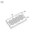
図5に示すように、本実施の形態において、固定破砕板30は、刃物鋼の板状の部材から作られ、複数の孔32を有している。孔32は、丸孔であっても良いし、或いは、破砕ロータの軸方向に長径を有する長孔であっても良い。また、孔32は、破砕ロータ34の軸方向の複数の列に沿って配置されている。軸に垂直な方向に隣接する孔32は、当該方向に、部分的に重複するような配置となっている。これは、後述するように、回転破砕刃36に引掛けられた処理物が、孔32の周囲などに接触して、これにより、処理物が折り曲げられるような機会をより増やすために有効である。なお、孔は、板状の部材を打ち抜くことにより形成することができる。
As shown in FIG. 5, in the present embodiment, the fixed crushing
また、図3に示すように、固定破砕板支持部40の断面はV字状であり、固定破砕板30の下端面、および、誘導版31の荷重受け部を形成する一部の下端面は、それぞれ、破砕ロータ34の軸方向に延びる角柱形状の固定刃押さえ主軸40の面と整合する。また、固定破砕板30の上端、および、誘導板31の上端は、それぞれ、破砕ロータ34の軸方向に延びるフレームアーム50により、その位置を規定される。さらに、固定破砕板30および誘導板31の長手方向(破砕ロータ34の軸方向)両端は、それぞれ、固定刃押さえ板52によりしっかりと固定される。このような構成により、固定破砕板30および誘導板31を、一つの固定破砕部材として使うことができる。また、固定破砕板30および誘導板31から構成される固定破砕部材により、破砕室29の下部が画定される。
Moreover, as shown in FIG. 3, the cross section of the fixed crushing
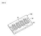
本実施の形態において、誘導板31の下端部には、破砕ロータ34の軸に沿って、切欠33が形成される。したがって、誘導板の下側は、部分的に開口する。図6は、本実施の形態にかかる誘導板31の斜視図である。図6に示すように、誘導版31の下端には、2箇所の切欠33が形成され、その間は、長手方向両端と同じだけ延びて、荷重受け部54を形成している。本実施の形態において、切欠33の長手方向の長さaは、120mm〜140mm、短辺方向の長さbは、約35mmである。
In the present embodiment, a
本実施の形態において、破砕ロータ34は、図7(a)、(b)に示すように、中実な直方体状の刃物鋼の本体35の4つの外周面に、それぞれ、破砕刃36を取り付けるための刃物鋼などで作られた板状部材37が、ねじなど取付具で本体35に取り付けられる。板状部材37には、周方向(破砕ロータの軸と垂直な方向)に破砕刃36がねじなどの取付具で取り付けられる。板状部材37は、破砕ロータ34の軸方向両端に斜面が形成されているのが望ましい。
In this embodiment, as shown in FIGS. 7A and 7B, the crushing
図3および図7(a)、(b)により理解できるように、破砕刃36は、正転(時計回り)方向(図7(b)の矢印X参照)、つまり、処理物の送り込み側に、その先端部分44が向くようになっている。破砕刃36の断面形状を、このように構成することにより、破砕ロータ34の正転時には、先端部分に、処理物が引っかかり易くなり、破砕ロータ34の回転に伴って、固定破砕板30の方に向けて移動される。
As can be understood from FIG. 3 and FIGS. 7A and 7B, the crushing
また、破砕ロータ34の軸38の一端は、モータ18に連結されており、モータ18の作動に伴って回転駆動される。本実施の形態において、破砕ロータ34は、基本的には、正転(図7(b)における矢印X方向)に回転する。また、本実施の形態において、モータ駆動回路(図示せず)にはショックリレーが接続されている。したがって、チップやワークなどの異物が混入して、たとえば、破砕刃34と固定破砕板30の内面との間、或いは、破砕刃34と誘導板31の内面との間に異物が挟まった状態となった場合など、過負荷により過電流がモータ駆動回路に流れた時には、ショックリレーがこれを検出し、所定の時間(たとえば5秒間)、モータを逆転(図7における矢印Y方向)するような設定となっている。
In addition, one end of the
無論、上述したように、基本的な通常動作において、正転するのみではなく、一定の運転タクト、たとえば、正転を45秒間、逆転(図3における反時計回り)を5秒間に設定しても良い。また、操作盤20上のスイッチ等をオペレータが操作することにより、上記運転タクトは任意に調整することが可能である。
Of course, as described above, in the basic normal operation, not only forward rotation but also a certain driving tact, for example, forward rotation is set to 45 seconds and reverse rotation (counterclockwise in FIG. 3) is set to 5 seconds. Also good. In addition, the operation tact can be arbitrarily adjusted by an operator operating a switch or the like on the
破砕ロータ34の軸38は、支持フレーム24および固定破砕板取り付けフレーム28略中央に設けられた孔を介して、モータの軸に連結される。破砕ロータ34と誘導板31との間の距離は、破砕ロータ34と固定破砕板30との間の距離よりも十分に大きくなるように破砕ロータ34は配置される。これは、破砕ロータ34の破砕刃36と固定破砕板30とは十分に近接し、これらの間で、後述するように切粉の破砕が行われる一方、破砕ロータ34の破砕刃36と誘導板31とは十分に離間し、切粉は互いに絡まりあった状態のまま、破砕ロータ34の下側を通って、固定破砕板30の側にまで搬送される。その一方、ワークやチップなどの異物は、十分に離間している破砕ロータ34の破砕刃36と誘導板31との間を通り抜けて、誘導板31の下部に設けられた孔33から落下する。
The
本実施の形態において、破砕ロータ34の破砕刃36と固定破砕板30との距離は、1.5mm、破砕ロータ34の破砕刃と誘導板31との距離は25mmに設定されている。無論、この距離に限定されるものではなく、切粉の細さや粘度、予想される異物の大きさにより適宜設定すればよい。
In the present embodiment, the distance between the crushing
このように構成された破砕処理装置10の動作について以下に説明する。始動の際に、操作者は、操作盤20の始動スイッチを押して、モータ18を起動し、破砕ロータ34を正転させる。本実施の形態においては、モータは、基本的には正転し、その回転が阻害され過電流が流れるときに逆転するように構成されているが、たとえば、前述したように、正転(図7(b)におけるX方向に)25秒、逆転(同図におけるY方向に)5秒というような、所望の運転タクトを設定しても良い。
The operation of the crushing
次いで、操作者は、たとえば、金属切粉、アルミ、ガラス、生ごみ、および、乾物などの処理物をホッパ14から破砕室29に投入する。或いは、工作機械の切粉排出口から排出され、コンベア装置にて運搬された金属切粉などの処理物が、ホッパ14から破砕室29に投入されるように構成されても良い。
Next, for example, the operator puts a processed material such as metal chips, aluminum, glass, garbage, and dry matter into the crushing
投入された処理物は、破砕ロータ34の破砕刃36の先端に引掛かり、破砕ロータ34の回転に伴って、送り込み側に向けて(正転方向に)、順次送り込まれる。送り込まれた処理物の一部は、固定破砕板30の配置された側に落下し、破砕刃36と固定破砕板の孔32の周囲に接触することにより、引っ張られ、或いは、折り曲げられる。このような引っ張りおよび折り曲げを繰り返すころにより、処理物は徐々に細かく破砕される。破砕された処理物は、孔32から落下し、破砕処理物収容箱22に収容される。
The charged processed material is caught at the tip of the crushing
その一方、送り込まれた処理物の一部は、破砕刃36の正転方向の回転に伴って、誘導板31の配置された側に送り込まれる。先に説明したように、破砕刃36と誘導板31とは十分に離間しているため、処理物は、破砕刃36の先端に引掛った状態で、破砕ロータ34の下部を通過して、固定破砕刃30の面にそって送り込まれる。この状態で、処理物は、固定破砕板30の長孔32の周囲などに接触することにより引っ張られ、あるいは、折り曲げを繰り返され、これにより破砕され、孔32から落下する。
On the other hand, a part of the processed product that has been sent in is sent to the side where the
このように、本実施の形態においては、固定破砕板と破砕刃との間では、引っ張りや折り曲げにより処理物を破砕しており、切断が行われないため、刃の破損等のおそれを著しく減じることが可能となる。 As described above, in the present embodiment, the processed product is crushed by pulling or bending between the fixed crushing plate and the crushing blade, and the cutting is not performed, so that the risk of damage to the blade is significantly reduced. It becomes possible.
その一方、処理物に混入したチップやワークなどの異物は、破砕ロータ34の回転に伴って、送り込み側に向けて(正転方向)に移動し、誘導板31の配置された側に達する。本実施の形態においては、破砕ロータ34の破砕刃36と誘導板31とは十分に離間しているため、誘導板31に達した異物は、破砕刃36に触れることなく、誘導板31の傾斜した内面にそって徐々に下方に移動し、最終的には、誘導板31の下方に形成された孔33から落下する。無論、異物が破砕刃36と誘導板31との間に挟まった場合には、破砕ロータ34の回転が阻害され、モータに過電流が流れる。したがって、モータは、異物を再度、誘導板31に斜面に沿って下方に移動させるように、所定の時間だけ逆回転する。
On the other hand, foreign matters such as chips and workpieces mixed in the processed material move toward the feeding side (forward direction) as the crushing
本実施の形態によれば、破砕ロータ34の正転方向の側には、当該破砕ロータ34の破砕刃36との距離が十分に離間するように、下方に向けて当該破砕ロータの軸に向けて傾斜した誘導板31を配置し、処理物に混入した異物は、誘導板31の斜面に沿って下方に移動し、当該誘導板31の下部に形成された孔33から外部に排出される。したがって、異物が破砕刃36と接触することによる破砕刃36の破損のおそれを著しく減じることが可能となる。また、破砕刃36と固定破砕板や誘導板との間に異物が挟まる可能性が少なくなるため、異物が挟まった際にモータを逆転させる状況が生じる可能性も小さい。したがって、処理物の破砕処理効率を向上させることも可能となる。
According to the present embodiment, on the side of the crushing
本発明は、以上の実施の形態に限定されることなく、特許請求の範囲に記載された発明の範囲内で、種々の変更が可能であり、それらも本発明の範囲内に包含されるものであることは言うまでもない。 The present invention is not limited to the above embodiments, and various modifications can be made within the scope of the invention described in the claims, and these are also included in the scope of the present invention. Needless to say.
上記実施の態様においては、直方体状の刃物鋼35の本体の4つの外周面に、それぞれ、板状部材37を取り付け、さらにその上に、周方向(つまり、破砕ロータの軸と垂直な方向)に破砕刃36が取り付けられる。また、破砕刃36の断面形状において、その先端が、送り込み側に向くようになっている。しかしながら、これに限定されるものではなく、種々の形状の破砕刃を利用することが可能である。図8ないし図11は、それぞれ、破砕ロータ34の変形例を示している。
In the above embodiment, the plate-shaped
図8(a)は破砕ロータ134の正面図、図8(b)は破砕刃136の形状を示す断面図である。この例では、破砕刃136が周方向に連続して配置される。また、図9(a),(b)に示す例では、円筒形の破砕ロータ234には、外周面に円周方向に複数の破砕刃236が螺旋状に形成されている。これらの破砕刃136、236は、破砕刃36と同様に、処理物の送り込み側に先端部分が向くようになっている。この例では、破砕刃136は、円筒形の刃物鋼を切削することにより形成することができる。
FIG. 8A is a front view of the crushing
図10(a)、(b)に示す例では、円筒形の破砕ロータ334の外周面には、円周方向に、複数の円錐状の破砕刃336が千鳥状に配置されている。各破砕刃336の下側部分には雄ネジが形成されている。したがって、破砕ロータ334の所定の位置に、雌ネジが形成されたネジ孔を穿孔しておくことで、破砕刃336をネジ止めにて取り付けることができる。したがって、ある破砕刃336が破損した場合でも、その破砕刃336のみを新規なものに交換することが可能である。図11(a)、(b)に示す例でも、円筒形の破砕ロータ434の外周面には、円周方向に、複数の円筒形の破砕刃436が千鳥状に配置されている。破砕刃336と同様に、各破砕刃436の下側部分には、雄ネジが形成され、破砕ロータ434に穿孔されたネジ孔にねじ込むことにより固定される。この破砕刃436は、円筒形であるが、その先端にフランジが形成されている。このフランジにより、処理物を引掛けて、固定破砕板の側に送り込むことが可能である。なお、図10および図11に示す例では、円筒形の本体を利用せずに、本実施の形態と同様に、直方体状の本体を利用しても良い。
In the example shown in FIGS. 10A and 10B, a plurality of conical crushing
このように、本発明においては、破砕する処理物に応じて、所望の破砕刃を有する破砕ロータを選び、最適な条件で処理物を破砕することができる。 As described above, in the present invention, a crushing rotor having a desired crushing blade can be selected according to the processed material to be crushed, and the processed material can be crushed under optimum conditions.
また、固定破砕板30は、少なくとも内面は平滑になっていたがこれに限定されるものではない。図12は、固定破砕板の他の例を示す図である。図12に示すように、固定破砕板130の中央部には、破砕ロータ34の軸と平行に、その厚みが薄くなっている薄肉部56が形成されている。薄肉部52が形成されることにより、固定破砕板130と、破砕ロータ34の軸との距離を小さくする、つまり、破砕ロータ34を固定破砕板130からより接近させることができ、これにより、破砕効率をより向上させることができる。
Further, the fixed crushing
10 破砕処理装置
12 破砕部
14 ホッパ
16 取り付け台
18 モータ
20 操作盤
24 支持フレーム
26 取り付け部
28 固定破砕板取り付けフレーム
30 固定破砕板
31 誘導板
32 孔
34 破砕ロータ
36 破砕刃
DESCRIPTION OF
Claims (7)
前記固定破砕部材が、前記破砕ロータの逆転方向の側に、当該破砕ロータの軸方向に延びるとともに、複数の孔が形成された第1の固定板と、前記破砕ロータの正転方向の側に、当該破砕ロータの軸方向に延びる第2の固定板とを有し、第1の固定板および第2の固定板とにより、断面形状が略V字状の固定破砕部材が形成され、かつ、前記第2の固定板の下端に設けられた切欠きにより、当該下端に孔が形成され、
第1の固定板との間隔が、第2の固定板との間の間隔よりも小さいように、前記破砕ロータの軸が、前記本体に回転自在に取り付けられたことを特徴とする破砕処理装置。 A crushing rotor provided with a plurality of crushing blades in the rotation direction on the outer peripheral surface, and a plurality of holes located outside the crushing rotor and crushing the processed material in cooperation with the crushing blades formed on the crushing rotor. A fixed crushing member having a motor, a motor connected to a shaft of the crushing rotor and rotating the crushing rotor in forward / reverse rotation, a driving means for driving and controlling the motor, and an input processed product The crushing rotor shaft is rotatably attached, and a main body for fixing the stationary crushing member is provided, and the workpiece is drawn on the crushing blade of the crushing rotor rotated forward by the driving means and rotated in the forward direction. In the crushing processing apparatus for crushing and feeding, crushing the processed material between the crushing blade and the hole of the fixed crushing plate, and discharging the processed material crushed from the hole,
The fixed crushing member extends in the axial direction of the crushing rotor on the side of the crushing rotor in the reverse direction, and on the side of the normal rotation direction of the crushing rotor in which a plurality of holes are formed. The second fixing plate extending in the axial direction of the crushing rotor, and the first fixing plate and the second fixing plate form a fixed crushing member having a substantially V-shaped cross section, and A hole is formed in the lower end by a notch provided in the lower end of the second fixing plate,
The crushing processing apparatus, wherein the shaft of the crushing rotor is rotatably attached to the main body so that a distance between the first fixing plate and the second fixing plate is smaller than a distance between the first fixing plate and the second fixing plate. .
前記第2の固定板が、下端部に複数の切欠を有し、隣接する切欠の間が、その両端部と同じ長さに延びる延長部を有し、当該両端部および延長部の下端が、前記押さえ主軸により支持されることを特徴とする請求項1ないし3の何れか一項に記載の破砕処理装置。 Providing a pressing spindle that extends in the axial direction of the crushing rotor and is fixed to the main body so as to support the lower end of the first fixing plate and the lower end of the second fixing plate;
The second fixing plate has a plurality of cutouts at the lower end, and has an extension extending between the adjacent cutouts to the same length as both ends, and the lower ends of the both ends and the extension are The crushing processing apparatus according to any one of claims 1 to 3, wherein the crushing processing apparatus is supported by the pressing main shaft.
Priority Applications (1)
| Application Number | Priority Date | Filing Date | Title |
|---|---|---|---|
| JP2004116615A JP4485242B2 (en) | 2004-04-12 | 2004-04-12 | Crusher |
Applications Claiming Priority (1)
| Application Number | Priority Date | Filing Date | Title |
|---|---|---|---|
| JP2004116615A JP4485242B2 (en) | 2004-04-12 | 2004-04-12 | Crusher |
Publications (2)
| Publication Number | Publication Date |
|---|---|
| JP2005296795A true JP2005296795A (en) | 2005-10-27 |
| JP4485242B2 JP4485242B2 (en) | 2010-06-16 |
Family
ID=35328989
Family Applications (1)
| Application Number | Title | Priority Date | Filing Date |
|---|---|---|---|
| JP2004116615A Expired - Fee Related JP4485242B2 (en) | 2004-04-12 | 2004-04-12 | Crusher |
Country Status (1)
| Country | Link |
|---|---|
| JP (1) | JP4485242B2 (en) |
Cited By (7)
| Publication number | Priority date | Publication date | Assignee | Title |
|---|---|---|---|---|
| JP2008132435A (en) * | 2006-11-28 | 2008-06-12 | Nt Techno Corp | Chip crushing apparatus |
| JP2010148346A (en) * | 2008-12-19 | 2010-07-01 | Tai-Her Yang | Bidirectional non-constant speed motor bidirectional output drive system |
| JP2010234352A (en) * | 2009-03-11 | 2010-10-21 | Sanki Tech Co Ltd | Crushing treatment apparatus |
| KR101567505B1 (en) | 2014-06-27 | 2015-11-11 | 주식회사 삼마테크 | Crushing method of scrap |
| JP2020131104A (en) * | 2019-02-19 | 2020-08-31 | 三愛エコシステム株式会社 | Crushing processing device |
| CN115055250A (en) * | 2022-07-29 | 2022-09-16 | 穆福长 | A soil remediation pretreatment device |
| CN118844219A (en) * | 2024-09-27 | 2024-10-29 | 川诚(吉林省)艺术文化设计有限公司 | A crushing device for waste straw and use method thereof |
-
2004
- 2004-04-12 JP JP2004116615A patent/JP4485242B2/en not_active Expired - Fee Related
Cited By (8)
| Publication number | Priority date | Publication date | Assignee | Title |
|---|---|---|---|---|
| JP2008132435A (en) * | 2006-11-28 | 2008-06-12 | Nt Techno Corp | Chip crushing apparatus |
| JP2010148346A (en) * | 2008-12-19 | 2010-07-01 | Tai-Her Yang | Bidirectional non-constant speed motor bidirectional output drive system |
| JP2010234352A (en) * | 2009-03-11 | 2010-10-21 | Sanki Tech Co Ltd | Crushing treatment apparatus |
| KR101567505B1 (en) | 2014-06-27 | 2015-11-11 | 주식회사 삼마테크 | Crushing method of scrap |
| JP2020131104A (en) * | 2019-02-19 | 2020-08-31 | 三愛エコシステム株式会社 | Crushing processing device |
| CN115055250A (en) * | 2022-07-29 | 2022-09-16 | 穆福长 | A soil remediation pretreatment device |
| CN115055250B (en) * | 2022-07-29 | 2024-05-24 | 长三角(义乌)生态环境研究中心 | A soil remediation pretreatment device |
| CN118844219A (en) * | 2024-09-27 | 2024-10-29 | 川诚(吉林省)艺术文化设计有限公司 | A crushing device for waste straw and use method thereof |
Also Published As
| Publication number | Publication date |
|---|---|
| JP4485242B2 (en) | 2010-06-16 |
Similar Documents
| Publication | Publication Date | Title |
|---|---|---|
| JP4485242B2 (en) | Crusher | |
| US5722604A (en) | Metal scrap shredder | |
| JP2011156446A (en) | Gypsum board breaker | |
| JP2000093826A (en) | Crushing equipment | |
| JP3814515B2 (en) | Crusher | |
| JP5480489B2 (en) | Crusher | |
| JP4411009B2 (en) | Crusher | |
| JP5221927B2 (en) | Crusher | |
| US20040069879A1 (en) | Cutting device, particularly for comminuting chips | |
| US5427162A (en) | Wood shaver | |
| JP4473596B2 (en) | Conveyor device with crushing device and crushing device for attaching conveyor device | |
| JP2004025157A (en) | Uniaxial crusher | |
| JP4825547B2 (en) | Chip cutting compression equipment | |
| WO2003009941A1 (en) | Shredder | |
| JP2016083625A (en) | Crushing processing unit | |
| JP3734464B2 (en) | Crusher | |
| JP2008093524A (en) | Shearing crusher | |
| JP5892740B2 (en) | Chip manufacturing apparatus and chip manufacturing method | |
| JP4751055B2 (en) | Volume reduction processing device and processing machine with volume reduction processing device | |
| JPH0957138A (en) | Single shaft crusher | |
| JP2008142652A (en) | Crushing processing device and conveying device | |
| JP4261434B2 (en) | Crusher | |
| JP2006346576A (en) | Single axial crusher | |
| JP4578306B2 (en) | Shearing crusher | |
| JPH1147626A (en) | Metal swarf volume reducing machine |
Legal Events
| Date | Code | Title | Description |
|---|---|---|---|
| A621 | Written request for application examination |
Free format text: JAPANESE INTERMEDIATE CODE: A621 Effective date: 20061214 |
|
| A977 | Report on retrieval |
Free format text: JAPANESE INTERMEDIATE CODE: A971007 Effective date: 20091013 |
|
| TRDD | Decision of grant or rejection written | ||
| A01 | Written decision to grant a patent or to grant a registration (utility model) |
Free format text: JAPANESE INTERMEDIATE CODE: A01 Effective date: 20100309 |
|
| A01 | Written decision to grant a patent or to grant a registration (utility model) |
Free format text: JAPANESE INTERMEDIATE CODE: A01 |
|
| A61 | First payment of annual fees (during grant procedure) |
Free format text: JAPANESE INTERMEDIATE CODE: A61 Effective date: 20100324 |
|
| R150 | Certificate of patent or registration of utility model |
Ref document number: 4485242 Country of ref document: JP Free format text: JAPANESE INTERMEDIATE CODE: R150 Free format text: JAPANESE INTERMEDIATE CODE: R150 |
|
| FPAY | Renewal fee payment (event date is renewal date of database) |
Free format text: PAYMENT UNTIL: 20130402 Year of fee payment: 3 |
|
| FPAY | Renewal fee payment (event date is renewal date of database) |
Free format text: PAYMENT UNTIL: 20140402 Year of fee payment: 4 |
|
| R250 | Receipt of annual fees |
Free format text: JAPANESE INTERMEDIATE CODE: R250 |
|
| R250 | Receipt of annual fees |
Free format text: JAPANESE INTERMEDIATE CODE: R250 |
|
| R250 | Receipt of annual fees |
Free format text: JAPANESE INTERMEDIATE CODE: R250 |
|
| R250 | Receipt of annual fees |
Free format text: JAPANESE INTERMEDIATE CODE: R250 |
|
| R250 | Receipt of annual fees |
Free format text: JAPANESE INTERMEDIATE CODE: R250 |
|
| R250 | Receipt of annual fees |
Free format text: JAPANESE INTERMEDIATE CODE: R250 |
|
| R250 | Receipt of annual fees |
Free format text: JAPANESE INTERMEDIATE CODE: R250 |
|
| R250 | Receipt of annual fees |
Free format text: JAPANESE INTERMEDIATE CODE: R250 |
|
| R250 | Receipt of annual fees |
Free format text: JAPANESE INTERMEDIATE CODE: R250 |
|
| R250 | Receipt of annual fees |
Free format text: JAPANESE INTERMEDIATE CODE: R250 |
|
| R250 | Receipt of annual fees |
Free format text: JAPANESE INTERMEDIATE CODE: R250 |
|
| LAPS | Cancellation because of no payment of annual fees |