JP2005296786A - Cleaning device - Google Patents
Cleaning device Download PDFInfo
- Publication number
- JP2005296786A JP2005296786A JP2004116277A JP2004116277A JP2005296786A JP 2005296786 A JP2005296786 A JP 2005296786A JP 2004116277 A JP2004116277 A JP 2004116277A JP 2004116277 A JP2004116277 A JP 2004116277A JP 2005296786 A JP2005296786 A JP 2005296786A
- Authority
- JP
- Japan
- Prior art keywords
- cleaning
- cleaned
- cleaning tank
- tank
- bubbles
- Prior art date
- Legal status (The legal status is an assumption and is not a legal conclusion. Google has not performed a legal analysis and makes no representation as to the accuracy of the status listed.)
- Pending
Links
Images

Landscapes
- Cleaning By Liquid Or Steam (AREA)
- Cleaning And De-Greasing Of Metallic Materials By Chemical Methods (AREA)
Abstract
【課題】気泡を被洗浄物に確実に接触させ、被洗浄物の気泡による洗浄を的確に行える洗浄装置を得る。
【解決手段】洗浄液を貯留する洗浄槽1、洗浄槽1に配設され被洗浄物を収容する被洗浄物容器2、洗浄槽1を構成する構成部材に設けられ洗浄槽構成部材の内面から気泡を供給する気泡発生部3を備え、気泡発生部3を設けた洗浄槽構成部材の内面部と前記洗浄槽構成部材の内面部に沿って延在する被洗浄物容器2の外面部とを所定間隔gを保って対向させるようにした。
【選択図】図1
An object of the present invention is to provide a cleaning device capable of accurately bringing bubbles into contact with an object to be cleaned and accurately cleaning the object to be cleaned with bubbles.
SOLUTION: A cleaning tank 1 for storing cleaning liquid, an object container 2 disposed in the cleaning tank 1 for storing an object to be cleaned, a bubble provided from an inner surface of the cleaning tank component provided in a component constituting the cleaning tank 1 A predetermined portion of the inner surface portion of the cleaning tank constituent member provided with the bubble generating portion 3 and the outer surface portion of the cleaning object container 2 extending along the inner surface portion of the cleaning tank constituent member. It was made to oppose, keeping the space | interval g.
[Selection] Figure 1
Description
この発明は、洗浄装置、特に、気泡を含む洗浄液による精密機械部品等の洗浄装置に関するものである。
この発明の属する技術分野は、主に精密,光学,機械部品等の脱脂洗浄であるが、これに限るものではなく、基板等の汚染物質、例えば研磨クズ、ガラス基板等の切断クズ等の粉体除去洗浄にも適用できる。
The present invention relates to a cleaning apparatus, and more particularly to a cleaning apparatus for precision machine parts and the like using a cleaning liquid containing bubbles.
The technical field to which this invention belongs is mainly degreasing and cleaning of precision, optics, mechanical parts, etc., but is not limited to this, and contaminants such as substrates, for example, powders such as polishing scraps, cutting scraps such as glass scraps, etc. It can also be applied to body removal cleaning.
工業的洗浄の分野において、従来、フロン系の溶剤や有機溶剤そのほか石油系などの特別な洗浄剤が用いられてきた。その結果、オゾン層の破壊や地下水,河川,海洋汚染などの環境問題を誘起することが明らかにされてきた。よって、環境負荷低減の目的から、これらの特殊な洗浄剤を用いない洗浄方法および洗浄装置の開発が進められている。
この発明の発明者らも、水を主体とした洗浄液中に微細な気泡を発生させ、その洗浄効果によって、従来のフロンやエタン系の溶剤に匹敵する洗浄度が得られる技術を開発した。
In the field of industrial cleaning, special cleaning agents such as chlorofluorocarbon solvents, organic solvents, and other petroleum solvents have been used. As a result, it has been clarified that it induces environmental problems such as ozone layer destruction and groundwater, river, and ocean pollution. Therefore, for the purpose of reducing the environmental load, development of a cleaning method and a cleaning apparatus that do not use these special cleaning agents is underway.
The inventors of the present invention have also developed a technique in which fine bubbles are generated in a cleaning liquid mainly composed of water, and a cleaning degree comparable to that of conventional chlorofluorocarbon or ethane-based solvents is obtained by the cleaning effect.
従来技術においては、主に被洗浄物を回転させることにより得られる相対速度によって、被洗浄物が気泡と衝突し、洗浄効率を高めることを可能とする洗浄装置が提案されている(例えば、特許文献1参照)。
しかし、この装置では、被洗浄物と気泡との高速な相対速度を得るためには、被洗浄物を高速に回転(1分間に100ないし1000回転以上)させるため、1)気泡が回転カゴに当って飛び散ってしまい、回転カゴ内に入らず、要求する高速の相対速度が得られないので洗浄度が向上しない、2)被洗浄物が傷ついてしまうという問題がある。また、高速回転機構を必要とするため装置が複雑化し、高コストとなる。
In the prior art, there has been proposed a cleaning apparatus that can improve the cleaning efficiency by causing the object to be cleaned to collide with bubbles by the relative speed obtained mainly by rotating the object to be cleaned (for example, patents). Reference 1).
However, in this apparatus, in order to obtain a high relative speed between the object to be cleaned and the bubbles, the object to be cleaned is rotated at a high speed (100 to 1000 rotations per minute). It hits and splatters, does not enter the rotating basket, and the required high relative speed cannot be obtained, so that the degree of cleaning is not improved. 2) There is a problem that an object to be cleaned is damaged. Further, since a high-speed rotation mechanism is required, the apparatus becomes complicated and the cost is increased.
また、回転カゴに入っている大量の被洗浄物を回転させて、回転カゴ内にある被洗浄物の相対位置関係が絶えず更新されながら、洗浄槽側面にある多数の洗浄水噴射ノズルと洗浄槽底にある空気吹込みノズルで気泡を発生させて洗浄することで洗浄効率を高めることを可能とする洗浄装置も提案されている(例えば、特許文献2参照)。
しかし、この装置では、回転カゴに大量の被洗浄物を入れて回転させるだけでは、未洗浄面を無くす可能性は低く、短時間で洗浄度を上げることはできない。また、洗浄槽側面に配置してある洗浄水噴射ノズルから供給される洗浄水では洗浄底から供給される気泡の流速を高めることはできず、逆に気泡を潰してしまう可能性があり、洗浄度の向上は図れない。さらに、気泡も回転カゴの底部一部にしか供給されないという問題がある。
In addition, a large number of objects to be cleaned in the rotating basket are rotated so that the relative positional relationship of the objects to be cleaned in the rotating basket is constantly updated, while a large number of cleaning water jet nozzles and cleaning tanks are provided on the side of the cleaning tank. There has also been proposed a cleaning device that can improve the cleaning efficiency by generating bubbles with an air blowing nozzle at the bottom and cleaning (for example, see Patent Document 2).
However, with this apparatus, simply putting a large amount of object to be cleaned in a rotating basket and rotating it is unlikely to eliminate the uncleaned surface, and the degree of cleaning cannot be increased in a short time. In addition, the cleaning water supplied from the cleaning water jet nozzle arranged on the side surface of the cleaning tank cannot increase the flow velocity of the bubbles supplied from the cleaning bottom, and conversely, the bubbles may be crushed. The degree cannot be improved. Furthermore, there is a problem that bubbles are only supplied to a part of the bottom of the rotating basket.
この発明は、気泡を被洗浄物に確実に接触させ、被洗浄物の気泡による洗浄を的確に行える洗浄装置を得ようとするものである。 An object of the present invention is to obtain a cleaning apparatus that can reliably bring bubbles into contact with an object to be cleaned and accurately clean the object to be cleaned with bubbles.
この発明に係る洗浄装置では、洗浄液を貯留する洗浄槽に配設され被洗浄物を収容する被洗浄物容器、前記洗浄槽を構成する構成部材に設けられ前記洗浄槽構成部材の内面から気泡を供給する気泡発生部を備え、前記気泡発生部を設けた洗浄槽構成部材の内面部と前記被洗浄物容器の外面部とを所定間隔を保って対向させるようにしたものである。 In the cleaning apparatus according to the present invention, the object to be cleaned is disposed in the cleaning tank for storing the cleaning liquid and the object to be cleaned is provided in the structural member constituting the cleaning tank. A bubble generating part to be supplied is provided, and an inner surface part of a cleaning tank constituent member provided with the bubble generating part and an outer surface part of the object container to be cleaned are opposed to each other with a predetermined interval.
この発明によれば、気泡を被洗浄物に確実に接触させ、被洗浄物の気泡による洗浄を的確に行える洗浄装置を得ることができる。 According to the present invention, it is possible to obtain a cleaning device that can reliably bring bubbles into contact with an object to be cleaned and accurately clean the object to be cleaned with bubbles.
実施の形態1.
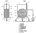
この発明による実施の形態1を図1および図2について説明する。図1は実施の形態1における洗浄装置の構成を示す2方向からの断面図であり、図1(a)は端面から見た断面図を示し、図1(b)は側面から見た断面図を示している。図2は実施の形態1における気泡発生部と被洗浄物間距離の関係を示す特性図である。
A first embodiment of the present invention will be described with reference to FIGS. FIG. 1 is a cross-sectional view from two directions showing the configuration of the cleaning device in
溶剤を用いた洗浄技術は、溶剤自身が油の強い溶解力を有するので、部品同士の重なりあいや微細構造を有する部品に対しても、溶剤が入り込む隙間が少しでもあれば、脱脂することが可能であった。ただし、これらは前記ですでに述べたように、環境およびコスト等に問題がある。
これに対して、気泡を用いた洗浄方法及び洗浄装置における課題は、気泡の作用した部分のみしか清浄化できず、複雑な形状、または微細な表面凸凹のある被洗浄物の洗浄度を高めることができないことである。微細気泡といえども、一般的には数10μm以上の大きさを有する。このため、多数の部品を洗浄カゴなどに入れて洗浄する方法では、必ず部品同士が密に重なった部分ができるために、気泡を複雑な形状、微細間表面凸凹のある個々部品の隅々にまで作用させることができなかった。
The cleaning technology using a solvent has a strong ability to dissolve oil, so even parts with overlapping parts or microstructures can be degreased if there is even a small gap for the solvent to enter. It was possible. However, as described above, these have problems in environment and cost.
On the other hand, the problem in the cleaning method and the cleaning apparatus using bubbles is that only the portion where bubbles act can be cleaned, and the cleaning degree of the object to be cleaned having a complicated shape or fine surface unevenness is increased. Is not possible. Even the fine bubbles generally have a size of several tens of μm or more. For this reason, in a method in which a large number of parts are placed in a cleaning basket and the like, the parts are always closely overlapped with each other. It was not possible to act until.
この発明による洗浄装置では、1)気泡発生部と被洗浄物との距離を短ギャップにすることにより、微細気泡と被洗浄物との相対速度を高速にすることができる、2)回転カゴ内に仕切りを設けることで、高速微細気泡流によって部品が吹き飛ばされるのを抑制(短ギャップ化を助ける)し、且つ回転カゴ回転中に部品の分散性をより高めることができる、3)回転カゴ内に支柱を設け、支柱からも微細気泡を供給することにより、高速微細気泡流による部品の吹き飛ばし抑制(短ギャップ化を助ける)、且つ微細気泡による洗浄効率を高めることができるといった相乗効果により、微細気泡を部品の隅々にまで作用させ複雑な形状や微細な表面凹凸を有する部品でも高い洗浄力を短時間で得ることができ、従来の洗浄技術における課題を解決することが可能となる。 In the cleaning apparatus according to the present invention, 1) the relative speed between the fine bubbles and the object to be cleaned can be increased by setting the distance between the bubble generating part and the object to be cleaned to be a short gap. By providing a partition, it is possible to suppress parts from being blown away by the high-speed fine bubble flow (helping to shorten the gap), and to further improve the dispersibility of the parts during rotation of the rotating basket. 3) In the rotating basket By providing a support column in the support column and supplying fine bubbles from the support column, it is possible to suppress the blow-off of parts by a high-speed fine bubble flow (helping to shorten the gap) and to improve the cleaning efficiency by the fine bubbles. Air bubbles can be applied to every part of the part, and high cleaning power can be obtained in a short time even for parts with complicated shapes and fine surface irregularities, which solves the problems of conventional cleaning technology. It is possible to become.
次に、この発明における課題の解決手段についてより具体的に述べる。
この発明の発明者らは、気泡洗浄の検討過程において、非常に重要なことを見出した。それは、部品の洗浄度は、気泡を含んだ洗浄液の流速に大きく依存するということである。これは、次の2点から明らかとなった。
(1)一点目として、部品表面には、気泡の直径よりも1桁以上小さいμmオーダーの凹凸が無数に存在するが、部品表面の凹凸よりも1桁以上大きい気泡をいくら作用させ続けても、凹部に付着した油を除去することはできない。
(2)2点目として、微細気泡は、流速をあげることで、部品表面で変形、或いはさらに微細化する。従って、高速の微細気泡を含んだ洗浄液を被洗浄物に供給することで、気泡直径よりも小さな構造付着した油も除去することが可能となり、洗浄度を高めることができた。結果としては、流速を2〜3倍にすると、洗浄度は4〜9倍と向上した。この実験結果は、被洗浄物に当る泡量(個数)は一定、つまり、流速によって処理時間を変化させて処理しているので、流速が洗浄度に効果大であることが明らかである。
微細気泡の流速としては、20cm/sec以上必要であり、好ましくは、50cm/sec以上あればなお良い。このように、微細気泡の流速を高めることで洗浄度が向上することがわかった。微細気泡流を高速化する手段としては、ポンプを大容量にすれば可能ですが、高コストになってしまうという問題がある。
よって、この発明の発明者らは、洗浄槽の形状、回転カゴの形状、気泡発生部の配置位置等を最適化(狭ギャップ化)し、被洗浄物と微細気泡との相対速度を高めることで、複雑な凸凹形状を有する被洗浄物の洗浄度の向上を実現した。
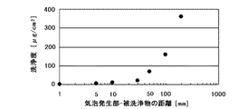
実験の結果、図2に示すように、気泡発生部と被洗浄物との距離を長くするに従い、洗浄度が指数関数的に悪くなったことから、気泡発生部と被洗浄物との距離は、なるべく近接させたほうがよく、少なくとも50mm以内がよく、好ましくは5mm以内がよい。
また、微細気泡を含んだ洗浄液との相対流速を高めることにより、密集した被洗浄物群の隙間の奥でも、微細気泡を供給でき、気泡洗浄による一括洗浄が可能となった。複雑な形状を有する大量の被洗浄物を入れる回転カゴは網状(メッシュ状)のものがよく、形状は多角形でもよいが、好ましくは円形がよい。洗浄槽底の形状は、洗浄槽側面の一対が、四角形または多角形でもよいが、好ましくは半円もしくは扇形になっている方がよい。気泡発生部は、一つのポンプから洗浄水を供給する場合、少なくとも一つ以上あればよく、好ましくは3つほどあればよい。最もよい組合せは、回転カゴの形状が円形、洗浄槽底が半円になっており、半円状の洗浄槽底内と回転カゴの距離が50mm以内、気泡発生部が洗浄槽底半円部分の底部と両側側面部に計3箇所配置されているのがよい。また、洗浄液の温度は、室温以上が好ましく、さらに好ましくは50℃以上がよい。この点については、この実施の形態1において説明する。
Next, means for solving the problems in the present invention will be described more specifically.
The inventors of the present invention have found that it is very important in the process of studying bubble cleaning. That is, the degree of cleaning of the parts greatly depends on the flow rate of the cleaning liquid containing bubbles. This became clear from the following two points.
(1) As a first point, there are innumerable irregularities in the order of μm that are one digit or more smaller than the diameter of the bubbles on the surface of the component, but no matter how many bubbles larger than the irregularities on the component surface continue to act. The oil adhering to the recess cannot be removed.
(2) As a second point, the fine bubbles are deformed or further refined on the surface of the component by increasing the flow velocity. Therefore, by supplying a cleaning liquid containing high-speed fine bubbles to the object to be cleaned, it is possible to remove oil adhered to a structure smaller than the bubble diameter, and the degree of cleaning can be improved. As a result, when the flow rate was increased 2 to 3 times, the degree of cleaning was improved 4 to 9 times. From this experimental result, it is clear that the amount (number) of bubbles hitting the object to be cleaned is constant, that is, processing is performed by changing the processing time depending on the flow rate, so that the flow rate is very effective for the degree of cleaning.
The flow rate of fine bubbles is required to be 20 cm / sec or more, and preferably 50 cm / sec or more. Thus, it was found that the degree of cleaning is improved by increasing the flow rate of the fine bubbles. As a means for speeding up the fine bubble flow, it is possible to increase the capacity of the pump, but there is a problem that the cost becomes high.
Therefore, the inventors of the present invention optimize the shape of the cleaning tank, the shape of the rotating basket, the arrangement position of the bubble generating part (narrow gap), and increase the relative speed between the object to be cleaned and the fine bubbles. As a result, the degree of cleaning of an object to be cleaned having a complicated uneven shape was improved.
As a result of the experiment, as shown in FIG. 2, as the distance between the bubble generating part and the object to be cleaned is increased, the degree of cleaning has deteriorated exponentially, so the distance between the bubble generating part and the object to be cleaned is It is better to make them as close as possible, at least within 50 mm, and preferably within 5 mm.
Further, by increasing the relative flow rate with the cleaning liquid containing fine bubbles, fine bubbles can be supplied even in the back of the gaps between the densely packed objects to be cleaned, and batch cleaning by bubble cleaning becomes possible. The rotating basket for storing a large amount of objects to be cleaned having a complicated shape is preferably net-like (mesh), and the shape may be polygonal, but preferably circular. As for the shape of the bottom of the cleaning tank, the pair of side surfaces of the cleaning tank may be quadrangular or polygonal, but preferably a semicircle or a sector. When supplying cleaning water from one pump, at least one bubble generating unit may be provided, and preferably three bubble generating units may be provided. The best combination is that the shape of the rotating basket is circular and the bottom of the washing tank is a semicircle, the distance between the semicircular washing tank bottom and the rotating basket is within 50 mm, and the bubble generation part is a semicircular part of the washing tank bottom It is good to arrange a total of three places on the bottom part and both side parts. The temperature of the cleaning liquid is preferably room temperature or higher, more preferably 50 ° C. or higher. This point will be described in the first embodiment.
もう一つの工夫として、回転カゴ内に仕切りを設けることで、回転カゴ中の大量被洗浄物の相対位置を絶えず変え、密集した大量の被洗浄物の分散性をより高めることで、被洗浄物の洗浄効率をより高めることができた。また、回転カゴ内の仕切りは、高速微細気泡流によって部品が吹き飛ばされるのを抑制するので、気泡発生部と被洗浄物との狭ギャップ化も実現できる。回転カゴ内に設ける仕切りの形状は、上記効果を実現可能であれば特に限定しないが、回転カゴ内に少なくとも一つ以上設け、回転カゴと同様に網状(メッシュ形状)にするのが好ましい。この点については、後述する実施の形態2において説明する。 As another contrivance, by providing a partition in the rotating basket, the relative position of a large amount of objects to be cleaned in the rotating basket is constantly changed, and the dispersibility of a large number of dense objects to be cleaned is further improved. It was possible to further improve the cleaning efficiency. Further, since the partition in the rotary basket suppresses the parts from being blown away by the high-speed fine bubble flow, it is possible to realize a narrow gap between the bubble generation part and the object to be cleaned. The shape of the partition provided in the rotating basket is not particularly limited as long as the above effects can be realized. However, it is preferable that at least one partition is provided in the rotating basket and has a mesh shape (mesh shape) like the rotating basket. This point will be described in a second embodiment to be described later.
さらに工夫した点は、回転カゴ外側だけでなく、回転カゴ内にも微細気泡発生可能な支柱を設けることで、回転カゴ内からも微細気泡洗浄が可能となり、且つ支柱の付加により回転カゴ中の余剰体積も減少できるため、支柱の気泡発生部と被洗浄物との距離が狭くなり、被洗浄物の洗浄効率をさらに高めることができた。また、回転カゴ内外から微細気泡を供給、且つ回転カゴ中の余剰体積を減少させていることから、被洗浄物が高速気泡流によって吹き飛ばされるのを抑制できるので、より洗浄度を向上できた。支柱の形状は、円形、多角形または歯車形が好ましく、さらに好ましくは、支柱から飛び出した羽根部材を設けるとなおよい。支柱から飛び出した羽は、大量被洗浄物内の中に入り込むため、支柱から飛び出した羽根部材部分からも気泡を発生させることで、他の被洗浄物内に埋もれている被洗浄物も同時に洗浄できた方がよく、より洗浄効率が向上し、短時間で洗浄を終えることが可能となる。この点については、後述する実施の形態3において説明する。 Furthermore, the ingenuity is that not only the outer side of the rotating basket but also the support that can generate fine bubbles is provided in the rotating basket, so that fine bubbles can be cleaned from inside the rotating basket. Since the surplus volume can also be reduced, the distance between the bubble generating portion of the column and the object to be cleaned is narrowed, and the cleaning efficiency of the object to be cleaned can be further increased. In addition, since fine bubbles are supplied from the inside and outside of the rotating basket and the excess volume in the rotating basket is reduced, it is possible to suppress the object to be cleaned from being blown away by the high-speed bubble flow, and thus the degree of cleaning can be further improved. The shape of the column is preferably circular, polygonal, or gear-shaped, and more preferably, a blade member protruding from the column is provided. Since the wings that have jumped out of the column enter into the mass to be cleaned, bubbles are also generated from the blade member that has jumped out of the column, so that the items to be cleaned buried in other items to be cleaned can be cleaned at the same time. It is better to be able to improve the cleaning efficiency, and the cleaning can be completed in a short time. This point will be described in a third embodiment described later.
このように、この発明は、気泡発生部と被洗浄物との距離を狭ギャップ化し、気泡流の相対速度を高める手段と、回転カゴ内に仕切りを設け、大量部品の拡散性をより向上させ、且つ気泡発生部と被洗浄物との距離の狭ギャップ化を維持できる手段と、回転カゴ内に気泡発生可能な支柱を設け、回転カゴ内外から被洗浄物を洗浄でき、且つ気泡発生部と被洗浄物との距離を狭ギャップ化に維持できる手段を備えており、被洗浄物の洗浄度向上、均一処理性能向上及び処理時間の短縮を図ることが可能な洗浄装置であることを特徴とする。
さらに言えば、被洗浄物を入れたカゴは、停止していても、これらの手段は有効に作用する。すなわち、図1について説明したような回転式ではなく、静置式であっても良い。
As described above, the present invention provides a means for increasing the relative speed of the bubble flow by narrowing the distance between the bubble generating part and the object to be cleaned, and a partition in the rotating basket, thereby further improving the diffusibility of a large number of parts. And a means capable of maintaining a narrow gap between the bubble generating part and the object to be cleaned, a support column capable of generating bubbles in the rotating basket, the object to be cleaned can be cleaned from inside and outside the rotating basket, and the bubble generating part It has a means capable of maintaining a narrow gap with the object to be cleaned, and is a cleaning apparatus capable of improving the degree of cleaning of the object to be cleaned, improving the uniform processing performance and shortening the processing time. To do.
Furthermore, even if the basket containing the object to be cleaned is stopped, these means work effectively. That is, it may be a stationary type instead of the rotational type described with reference to FIG.
図1において、洗浄槽1には回転カゴ2が収納されている。回転カゴ2は網状(メッシュ状)部材からなる円盤状の外形を有し、円板状の側面部2a,2bおよび周面部2cで構成される。回転カゴ2は円形形状を持つ側面部2a,2bの中心部分に設けられた回転カゴ支点を中心として周面部2cが周回し回転するように設定されている。
洗浄槽1は洗浄液を貯留する容器を構成し回転カゴ2を洗浄液に浸漬した状態で収納する。洗浄槽1は、回転カゴ2の側面部2a,2bに対向する側板1a,1bを有する扁平な箱体により構成される。
In FIG. 1, a
The
洗浄槽1の対向する側板の一組1a,1bは、洗浄槽1の底部において半円形状になっている。洗浄槽1内部には、被洗浄物を入れる回転カゴ2を備え、回転カゴ2の側面形状は円形となっている。回転カゴ2内には、被洗浄物が多数(1個〜千数個)入れることが可能である。回転カゴ2は、回転カゴ支点6を中心に垂直方向に回転するように設定してある。
洗浄槽1の側板1a,1bの下端における半円形状部分の周縁を連接する曲面部Aは洗浄槽1の底部壁面を構成する洗浄槽1の構成部材を回転カゴ2の周面部に対向して湾曲することによって形成され、回転カゴ2の周面部1cに対し前記回転カゴ2の周面半円分に相当する所定の周方向範囲にわたり微小ギャップgからなる所定間隔を保って対向している。
気泡発生部3は、洗浄槽1内部に設置してもよいが、洗浄槽1の外部に設置してもよい。この実施の形態では気泡発生部3が洗浄槽1の外側に3つ取り付けられており、気泡発生部3の先端は洗浄槽1の底部に設けられた曲面部Aの回転カゴ2に対向する面と同一の位置に設けられている。3つの気泡発生部3と被洗浄物が入った回転カゴ2は、少なくとも回転カゴ2の半円分は、洗浄槽1の底部に設けられた曲面部Aと一定のギャップgになるように回転カゴ2と洗浄槽1の位置を調整してある。回転カゴ2の大きさは、洗浄槽1の底部に設けられた曲面部Aと回転カゴ2とのギャップが約5mmになるように作製してある。
各気泡発生部3には、流量調整弁4が備えられており、ポンプ5から供給される洗浄液の流量を可変調整できるようにしている。洗浄液には、微細気泡の生成に必須の添加剤が含まれている。また、洗浄液を加熱できるようにヒーター7も設置してある。
ヒーター7は投げ込み式ヒーターに限らず、他槽にて加熱させておいた洗浄液を槽内に供給してもよい。
A pair of opposing
The curved surface portion A connecting the peripheral edges of the semicircular portions at the lower ends of the
The
Each
The heater 7 is not limited to the throwing heater, and cleaning liquid heated in another tank may be supplied into the tank.
このように被洗浄物と気泡発生部との距離を狭ギャップ化した新規洗浄装置と洗浄槽底が円形ではなく四角形であり、且つ回転カゴの形状が六角形で、少なくとも一つの気泡発生部と回転カゴとの距離が最小点となる位置で約50mmになるように調整してある従来の洗浄装置で、それぞれ機械部品の脱脂洗浄を行った。処理条件は、以下の通りである。被洗浄物個数は300個、回転カゴの回転数は1分間に10回転、各気泡発生部への洗浄水の流量は約7L/min(総計約20L/min=気泡発生部×3)、処理温度は約50℃、処理時間は5minとした。洗浄度の比較は、被洗浄物に付着している残油濃度で行った。その結果、従来の洗浄装置で洗浄した被洗浄物の残油濃度は約58μg/cm2だったのに対し、新規洗浄装置では約22μg/cm2と約3倍洗浄度が向上した。また、従来の洗浄装置で、新規洗浄装置で処理した被洗浄物の油濃度を得るためには、処理時間を15minも行わなければならないため、処理時間も1/3に短縮できた。さらに、この実施の形態では、洗浄槽内に洗浄液がある状態で処理を行なっているが、これに限るものではなく、洗浄液を他槽から供給し、微細気泡によるシャワー方式で行っても、同等以上の効果が得られる。 In this way, a new cleaning device in which the distance between the object to be cleaned and the bubble generating part is narrowed and the bottom of the cleaning tank is not a circle but a square, and the shape of the rotating basket is a hexagon, and at least one bubble generating part and The machine parts were each degreased and cleaned with a conventional cleaning apparatus that was adjusted so that the distance from the rotary basket was about 50 mm at the minimum point. The processing conditions are as follows. The number of objects to be cleaned is 300, the rotation speed of the rotating basket is 10 rotations per minute, the flow rate of cleaning water to each bubble generating part is about 7 L / min (total about 20 L / min = bubble generating part × 3), processing The temperature was about 50 ° C. and the treatment time was 5 min. The degree of cleaning was compared with the residual oil concentration adhering to the object to be cleaned. As a result, the residual oil concentration of the object cleaned by the conventional cleaning apparatus was about 58 μg / cm 2 , whereas the new cleaning apparatus improved the degree of cleaning by about 3 times to about 22 μg / cm 2 . In addition, in order to obtain the oil concentration of the object to be cleaned processed by the new cleaning device with the conventional cleaning device, the processing time must be as long as 15 minutes, so that the processing time can be shortened to 1/3. Furthermore, in this embodiment, the treatment is performed in a state where there is a cleaning liquid in the cleaning tank, but the present invention is not limited to this, and it is equivalent even if the cleaning liquid is supplied from another tank and is performed by a shower method using fine bubbles. The above effects can be obtained.
この発明による実施の形態1によれば、気泡を含む洗浄液を貯留する洗浄槽1、前記洗浄槽1に配設され被洗浄物を収容する回転カゴ2からなる回転可能な被洗浄物容器、前記洗浄槽1を構成する構成部材に設けられ前記洗浄槽構成部材の内面から気泡を供給する気泡発生部3を備え、前記回転カゴ2からなる被洗浄物容器の回転に応じその回転カゴ支点6からなる回転中心のまわりで周回し洗浄液が流通可能な周面部2cを前記回転カゴ2からなる被洗浄物容器の外面部に形成するとともに、前記回転カゴ2からなる被洗浄物容器2の周面部2cに沿い延在して対向する曲面部Aを前記洗浄槽1の構成部材の内面に形成し、前記洗浄槽1の曲面部Aの内面を前記回転カゴ2からなる被洗浄物容器の周面部2cの外面に対し前記回転カゴ2の周面半円分に相当する所定の周方向範囲にわたり微小ギャップgからなる所定間隔を保って対向させ、しかも、前記洗浄槽1の前記曲面部Aに所定の周方向間隔を置いて前記洗浄槽構成部材からなる前記曲面部Aの内面から気泡を供給する複数の気泡発生部3を設けたので、被洗浄物と気泡発生部との距離を狭ギャップにすることで、被洗浄物に接触する微細気泡の相対速度を高めることができるため、高い洗浄度、効率的な洗浄、処理時間の短縮が可能となり、気泡を被洗浄物に確実に接触させ、被洗浄物の気泡による洗浄を的確に行える洗浄装置を得ることができる。
According to
実施の形態2.
この発明による実施の形態2を図3について説明する。図3は実施の形態2における洗浄装置の構成を示す2方向からの断面図であり、図3(a)は端面から見た断面図を示し、図3(b)は側面から見た断面図を示している。
この実施の形態2において、ここで説明する特有の構成および方法以外の構成および方法については、先に説明した実施の形態1における構成および方法と同一の構成内容および方法内容を具備し、同様の作用を奏するものである。図中、同一符号は同一または相当部分を示す。
A second embodiment of the present invention will be described with reference to FIG. 3 is a cross-sectional view from two directions showing the configuration of the cleaning apparatus in the second embodiment, FIG. 3 (a) is a cross-sectional view seen from the end surface, and FIG. 3 (b) is a cross-sectional view seen from the side. Is shown.
In the second embodiment, the configuration and method other than the specific configuration and method described here have the same configuration and method as the configuration and method in the first embodiment described above. It has an effect. In the drawings, the same reference numerals indicate the same or corresponding parts.
この実施の形態2で、図3に示すように、実施の形態1における洗浄装置の回転カゴ内に網状の仕切り部材8を4つ均等に設けた以外は、実施の形態1と同様の処理条件で処理を行なった。
その結果、仕切りを設けることで、被洗浄物の残油濃度は約10μg/cm2と、仕切りがない従来の洗浄方法と比較して約6倍洗浄度が向上した。また、従来の洗浄装置で、この発明による洗浄装置で処理した被洗浄物の油濃度を得るためには、処理時間を20minも行わなければならないため、処理時間も1/4に短縮できた。さらに、この実施の形態2において、仕切り部材8の形状は網状に限るものではなく、板状のものであっても同様の効果が得られる。さらに、仕切り部材8の数は1つ以上、さらに好ましくは均等に8つでも、同様の効果が得られる。
In the second embodiment, as shown in FIG. 3, the same processing conditions as in the first embodiment, except that four mesh-
As a result, by providing the partition, the residual oil concentration of the object to be cleaned was about 10 μg / cm 2 , which was about 6 times higher than the conventional cleaning method without the partition. Further, in order to obtain the oil concentration of the object to be cleaned processed by the cleaning apparatus according to the present invention with the conventional cleaning apparatus, the processing time must be as long as 20 minutes, so that the processing time can be shortened to 1/4. Furthermore, in the second embodiment, the shape of the
この発明による実施の形態2によれば、実施の形態1における構成において、前記回転カゴ2からなる被洗浄物容器の内部に被洗浄物の回転方向の移動を規制する仕切り部材8を設けたので、複雑な形状を有する大量部品の洗浄装置において、回転カゴ内に仕切りを設けることで、部品の重なりを緩和し、且つ被洗浄物と気泡発生部との狭ギャップ化を維持できるため、高い洗浄度、効率的な洗浄、処理時間の短縮が可能となる。
According to the second embodiment of the present invention, in the configuration in the first embodiment, the
実施の形態3.
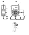
この発明による実施の形態3を図4について説明する。図4は実施の形態3における洗浄装置の構成を示す2方向からの断面図であり、図4(a)は端面から見た断面図を示し、図4(b)は側面から見た断面図を示している。
この実施の形態3において、ここで説明する特有の構成および方法以外の構成および方法については、先に説明した実施の形態1および実施の形態2における構成および方法と同一の構成内容および方法内容を具備し、同様の作用を奏するものである。図中、同一符号は同一または相当部分を示す。
A third embodiment of the present invention will be described with reference to FIG. 4 is a cross-sectional view from two directions showing the configuration of the cleaning device in
In the third embodiment, configurations and methods other than the specific configurations and methods described here are the same as the configurations and methods in the first and second embodiments described above. Have the same effect. In the drawings, the same reference numerals indicate the same or corresponding parts.
この実施の形態3では、図4に示すように、実施の形態2における構成の洗浄装置の回転カゴ2内に、均等に4つの羽根部材9aが付加された円筒状の支柱9が備えられ、支柱9および4つの羽根部材9aから微細気泡が供給されるようにした以外は、実施の形態2と同様の処理を行った。ただし、ポンプからの総流量を一定とするため、流量は約5L/min(総計約20L/min=気泡発生部×4)としている。
その結果、被洗浄物の残油濃度は、約5μg/cm2と従来の洗浄装置と比較して約12倍洗浄度が向上した。また、従来の洗浄装置で、新規洗浄装置で処理した被洗浄物の油濃度を得るためには、処理時間を30min以上も行わなければならないため、処理時間も1/6に短縮できた。
さらに、この実施の形態3において、支柱9の形状は、多角形、または歯車形でもよく、羽根部材9aの数も少なくとも1つ以上好ましくは4つ以上あれば、同様の効果が得られる。
In this
As a result, the residual oil concentration of the object to be cleaned was about 5 μg / cm 2 , which was about 12 times higher than the conventional cleaning device. In addition, in order to obtain the oil concentration of the object to be cleaned processed by the new cleaning apparatus with the conventional cleaning apparatus, the processing time must be performed for 30 minutes or more, so the processing time can be shortened to 1/6.
Furthermore, in
この発明による実施の形態3によれば、実施の形態1または実施の形態2における構成において、前記回転カゴ2からなる被洗浄物容器の回転カゴ支点6で構成された回転中心部分に設けられた支柱9からなる支承部材を備え、前記支柱9からなる支承部材に羽根部材9aとして構成された気泡発生部3を設けたので、回転カゴ2からなる被洗浄物容器内に支柱9からなる支承部材を設け、さらに支柱9からなる支承部材にも気泡発生部3を設けることで、被洗浄物と気泡発生部との狭ギャップ化を維持し、且つ、被洗浄物容器内または内外から被洗浄物を洗浄できるため、高い洗浄度、効率的な洗浄、処理時間の短縮が可能となる。
According to the third embodiment of the present invention, in the configuration in the first or second embodiment, the rotation center portion formed by the rotation basket fulcrum 6 of the object container made of the
実施の形態4.
この発明による実施の形態4を説明する。
この実施の形態4において、ここで説明する特有の構成および方法以外の構成および方法については、先に説明した実施の形態1から実施の形態3までにおける構成および方法と同一の構成内容および方法内容を具備し、同様の作用を奏するものである。
In the fourth embodiment, configurations and methods other than the specific configurations and methods described here are the same as the configurations and methods in the first to third embodiments described above. And has the same effect.
被洗浄物の洗浄が脱脂洗浄でなく、被洗浄物に付着している粉体であること、室温(18℃)で処理した以外は、実施例1と同様の処理条件で処理を行なった。その結果、従来の洗浄装置は、被洗浄物に付着している粉体を30%程度しか除去できないのに対し、新規洗浄装置では約90%以上除去できた。 The processing was performed under the same processing conditions as in Example 1 except that the cleaning of the object to be cleaned was not a degreasing cleaning but a powder adhering to the object to be cleaned and that the object was processed at room temperature (18 ° C.). As a result, the conventional cleaning apparatus can remove only about 30% of the powder adhering to the object to be cleaned, whereas the new cleaning apparatus can remove about 90% or more.
この発明による実施の形態4によれば、粉体を付着した被洗浄物を室温(18℃)で処理することにより、被洗浄物の粉体を有効に除去することができる。 According to the fourth embodiment of the present invention, the object to be cleaned can be effectively removed by processing the object to which the powder is adhered at room temperature (18 ° C.).
1 洗浄槽、2 回転カゴ、3 気泡発生部、4 流量調整弁、5 ポンプ、6 回転カゴ支点、7 ヒーター、8 仕切り部材、9 支柱。
DESCRIPTION OF
Claims (6)
6. The cleaning apparatus according to claim 3, further comprising a support member provided at a rotation center portion of the object container to be cleaned, wherein the support member is provided with a bubble generating portion.
Priority Applications (1)
| Application Number | Priority Date | Filing Date | Title |
|---|---|---|---|
| JP2004116277A JP2005296786A (en) | 2004-04-12 | 2004-04-12 | Cleaning device |
Applications Claiming Priority (1)
| Application Number | Priority Date | Filing Date | Title |
|---|---|---|---|
| JP2004116277A JP2005296786A (en) | 2004-04-12 | 2004-04-12 | Cleaning device |
Publications (1)
| Publication Number | Publication Date |
|---|---|
| JP2005296786A true JP2005296786A (en) | 2005-10-27 |
Family
ID=35328982
Family Applications (1)
| Application Number | Title | Priority Date | Filing Date |
|---|---|---|---|
| JP2004116277A Pending JP2005296786A (en) | 2004-04-12 | 2004-04-12 | Cleaning device |
Country Status (1)
| Country | Link |
|---|---|
| JP (1) | JP2005296786A (en) |
Cited By (1)
| Publication number | Priority date | Publication date | Assignee | Title |
|---|---|---|---|---|
| JP2007288134A (en) * | 2006-03-22 | 2007-11-01 | Dainippon Screen Mfg Co Ltd | Substrate processing apparatus |
Citations (6)
| Publication number | Priority date | Publication date | Assignee | Title |
|---|---|---|---|---|
| JPS5436067A (en) * | 1977-08-26 | 1979-03-16 | Asahi Denka Kogyo Kk | Washing machine |
| JPH0531285A (en) * | 1991-01-12 | 1993-02-09 | Daewoo Electronics Co Ltd | Washing machine having bubble generator and method of washing laundry using bubbles |
| JPH05345171A (en) * | 1992-06-11 | 1993-12-27 | Keihin Seiki Mfg Co Ltd | Work cleaning method and cleaning device |
| JPH06134347A (en) * | 1992-10-23 | 1994-05-17 | Takuo Mochizuki | Wet jet type washing device |
| JPH07227582A (en) * | 1994-02-18 | 1995-08-29 | Uchinami Techno Clean:Kk | Rotary submersible cleaning device |
| JP2002086094A (en) * | 2000-09-13 | 2002-03-26 | Sugino Mach Ltd | Submerged washing device |
-
2004
- 2004-04-12 JP JP2004116277A patent/JP2005296786A/en active Pending
Patent Citations (6)
| Publication number | Priority date | Publication date | Assignee | Title |
|---|---|---|---|---|
| JPS5436067A (en) * | 1977-08-26 | 1979-03-16 | Asahi Denka Kogyo Kk | Washing machine |
| JPH0531285A (en) * | 1991-01-12 | 1993-02-09 | Daewoo Electronics Co Ltd | Washing machine having bubble generator and method of washing laundry using bubbles |
| JPH05345171A (en) * | 1992-06-11 | 1993-12-27 | Keihin Seiki Mfg Co Ltd | Work cleaning method and cleaning device |
| JPH06134347A (en) * | 1992-10-23 | 1994-05-17 | Takuo Mochizuki | Wet jet type washing device |
| JPH07227582A (en) * | 1994-02-18 | 1995-08-29 | Uchinami Techno Clean:Kk | Rotary submersible cleaning device |
| JP2002086094A (en) * | 2000-09-13 | 2002-03-26 | Sugino Mach Ltd | Submerged washing device |
Cited By (1)
| Publication number | Priority date | Publication date | Assignee | Title |
|---|---|---|---|---|
| JP2007288134A (en) * | 2006-03-22 | 2007-11-01 | Dainippon Screen Mfg Co Ltd | Substrate processing apparatus |
Similar Documents
| Publication | Publication Date | Title |
|---|---|---|
| CN103372806B (en) | Automatic polishing equipment for surface treatment of complex curved surface contour part | |
| JP5466638B2 (en) | Apparatus and method for cleaning semiconductor substrate | |
| JP2011508958A (en) | Apparatus and method for wet treatment of disc-like objects | |
| CN105414070B (en) | A kind of Spinneret faceplate cleaning device | |
| JP6053624B2 (en) | Fine bubble processing equipment | |
| JP2010532556A5 (en) | ||
| JP3481891B2 (en) | Bearing cleaning equipment | |
| CN104624568A (en) | Cleaning equipment | |
| KR102419069B1 (en) | plate glass cleaning device | |
| JP6903665B2 (en) | Equipment and methods for cleaning objects with surface layers to be removed | |
| JP2001129499A (en) | Cleaning device and its operating method | |
| JP2005296786A (en) | Cleaning device | |
| CN106002595A (en) | Polishing treatment equipment and method | |
| JP6454147B2 (en) | Work 3D rotating device | |
| CN105420825B (en) | A kind of Spinneret faceplate cleans scaler | |
| CN209036280U (en) | The post-processing unit of chemical-mechanical polishing system and wafer | |
| ES2914620T3 (en) | Surface treatment device and surface treatment method using said device | |
| JP2009088227A5 (en) | ||
| JP2013013893A (en) | Washing apparatus | |
| KR100862231B1 (en) | Cleaning liquid jetting apparatus and substrate cleaning apparatus having the same | |
| JP3219375B2 (en) | Scrub cleaning member, substrate processing apparatus using the same, and cleaning brush | |
| JP6379540B2 (en) | Cleaning device and cleaning method | |
| JPH07100229A (en) | Spherical body washing device | |
| US20100307539A1 (en) | Substrate liquid processing apparatus, substrate liquid processing method, and storage medium having substrate liquid processing program stored therein | |
| CN204913566U (en) | Cleaning device of lacquer tumour on object periphery |
Legal Events
| Date | Code | Title | Description |
|---|---|---|---|
| A621 | Written request for application examination |
Free format text: JAPANESE INTERMEDIATE CODE: A621 Effective date: 20061110 |
|
| A977 | Report on retrieval |
Free format text: JAPANESE INTERMEDIATE CODE: A971007 Effective date: 20090515 |
|
| A131 | Notification of reasons for refusal |
Free format text: JAPANESE INTERMEDIATE CODE: A131 Effective date: 20090519 |
|
| A521 | Written amendment |
Free format text: JAPANESE INTERMEDIATE CODE: A523 Effective date: 20090716 |
|
| A131 | Notification of reasons for refusal |
Free format text: JAPANESE INTERMEDIATE CODE: A131 Effective date: 20090818 |
|
| A521 | Written amendment |
Free format text: JAPANESE INTERMEDIATE CODE: A523 Effective date: 20091008 |
|
| A02 | Decision of refusal |
Free format text: JAPANESE INTERMEDIATE CODE: A02 Effective date: 20100316 |