JP2005296638A - Game machine - Google Patents
Game machine Download PDFInfo
- Publication number
- JP2005296638A JP2005296638A JP2005071187A JP2005071187A JP2005296638A JP 2005296638 A JP2005296638 A JP 2005296638A JP 2005071187 A JP2005071187 A JP 2005071187A JP 2005071187 A JP2005071187 A JP 2005071187A JP 2005296638 A JP2005296638 A JP 2005296638A
- Authority
- JP
- Japan
- Prior art keywords
- game board
- connector
- main body
- terminal
- body frame
- Prior art date
- Legal status (The legal status is an assumption and is not a legal conclusion. Google has not performed a legal analysis and makes no representation as to the accuracy of the status listed.)
- Withdrawn
Links
Images
Landscapes
- Pinball Game Machines (AREA)
Abstract
【課題】 本体枠の遊技盤装着枠に対し、一側部を支点として回動して遊技盤を装着するときに、その遊技盤の回動動作に伴って本体枠側コネクタと遊技盤側コネクタとを電気的に接続することができる遊技機を提供する。
【解決手段】 遊技機の本体枠20に設けられた遊技盤装着枠110の一側部に対し、遊技盤140の一側部が係脱可能に係合され、その係合部を支点として遊技盤140が遊技盤装着枠に沿う装着位置まで回動されることで遊技盤装着枠110に遊技盤140が着脱交換可能に装着され、その遊技盤140の回動動作に伴って本体枠側コネクタ120と遊技盤側コネクタ170とが電気的に接続される。
【選択図】 図19
PROBLEM TO BE SOLVED: To mount a game board on a game board mounting frame of a main body frame with one side as a fulcrum and attach the main body frame side connector and the game board side connector along with the turning operation of the game board. A gaming machine capable of being electrically connected to each other is provided.
SOLUTION: One side part of a game board 140 is detachably engaged with one side part of a game board mounting frame 110 provided on a main body frame 20 of the gaming machine, and the game is performed with the engaging part as a fulcrum. When the board 140 is rotated to the mounting position along the game board mounting frame, the game board 140 is detachably mounted on the game board mounting frame 110, and the main body frame side connector is attached as the game board 140 rotates. 120 and the game board side connector 170 are electrically connected.
[Selection] FIG.
Description
この発明は、遊技機に関し、例えば、球(パチンコ球)を用いて遊技を行う遊技機に関する。 The present invention relates to a gaming machine, for example, a gaming machine that plays a game using a ball (pachinko ball).
遊技機、例えば、パチンコ機において、遊技機の基枠(本体枠)に対し、ヒンジ機構によって遊技盤の一側部が回動並びに離脱可能に支持され、基枠(本体枠)と遊技盤との相互に、遊技盤を閉じ位置まで回動したときに、その回動動作に伴って電気的に接続される電気配線接続用の一対のコネクタが配設された構造の遊技機が知られている(例えば、特許文献1参照)。
前記したような構造をもつ遊技機においては、一般的に、本体枠(基枠)と遊技盤との相互に配設される一対のコネクタに対し、遊技に関連する信号(例えば、DC5V)を伝達するための信号線に対する複数の信号端子や本体枠側から遊技盤側に電源(例えば、DC34VあるいはDC12V)を供給する電源線に対する電源端子及びグランド端子がそれぞれ配設されており、本体枠に対し遊技盤を着脱交換する度毎に、信号線や電源線を外したりあるいは接続する煩わしい手間を解消することができる。
また、前記したような構造をもつ遊技機においては、遊技盤の交換装着の際には、前もって遊技機の本体枠側に配置された電源スイッチをOFFし、遊技盤の交換装着が完了した後、電源スイッチをONするように取り扱わなければならない。
ところが、遊技盤の交換作業者が不慣れな場合等において、遊技盤を交換装着する際、遊技機の電源スイッチをONのまま遊技盤を脱着交換する場合がある。
そして、遊技機の電源スイッチがONの状態で遊技盤が交換装着される際、一対のコネクタにおいて、電圧が最も高いDC34Vの電源端子がグランド端子よりも先に接続されることがある。すると、DC12V、DC5Vが供給される回路をもつ回路基板上の電子部品(例えば、ICチップ、トランジスタ等の電子部品)に対し設計経路とは異なる経路で電流が流れ、回路基板上の電子部品が過電流によって破損される場合がある。
In a gaming machine having the structure as described above, generally, a signal related to a game (for example, DC5V) is sent to a pair of connectors disposed between a main body frame (base frame) and a game board. A plurality of signal terminals for signal lines to be transmitted and a power supply terminal and a ground terminal for a power supply line for supplying power (for example, DC34V or DC12V) from the main body frame side to the game board side are respectively arranged on the main body frame. On the other hand, every time the game board is attached and detached, the troublesome trouble of disconnecting or connecting the signal line and the power line can be eliminated.
In addition, in the gaming machine having the above-described structure, when the game board is replaced and installed, the power switch arranged on the main body frame side of the gaming machine is turned off in advance, and the replacement of the game board is completed. The power switch must be handled to turn on.
However, when a game board replacement operator is unfamiliar or the like, when the game board is replaced and installed, the game board may be removed and replaced while the power switch of the gaming machine is turned on.
When the game board is exchanged and mounted while the power switch of the gaming machine is ON, the DC34V power terminal having the highest voltage may be connected before the ground terminal in the pair of connectors. Then, a current flows through an electronic component on the circuit board (for example, an electronic component such as an IC chip or a transistor) having a circuit supplied with DC12V and DC5V through a path different from the design path. It may be damaged by overcurrent.
この発明の目的は、前記問題点に鑑み、本体枠の遊技盤装着枠に対し、一側部を支点として回動して遊技盤を装着するときに、その遊技盤の回動動作に伴って本体枠側コネクタと遊技盤側コネクタとが電気的に接続される際、グランド端子を電源端子よりも先に接続することができ、電子部品が過電流によって破損される不具合を防止することができる遊技機を提供することである。 In view of the above-mentioned problems, the object of the present invention is to follow the turning operation of the game board when the game board is mounted by rotating about one side with respect to the game board mounting frame of the main body frame. When the main body frame side connector and the game board side connector are electrically connected, the ground terminal can be connected before the power supply terminal, thereby preventing the electronic component from being damaged due to overcurrent. It is to provide a gaming machine.
前記目的を達成するために、請求項1の発明に係る遊技機は、
「遊技機の本体枠に設けられた遊技盤装着枠の一側部に対し、遊技盤の一側部が係脱可能に係合され、その係合部を支点として前記遊技盤が前記遊技盤装着枠に沿う装着位置まで回動されることで前記遊技盤装着枠に前記遊技盤が着脱交換可能に装着される遊技機であって、
前記本体枠と前記遊技盤には、前記遊技盤装着枠に対する前記遊技盤の回動動作に伴って電気的に接続される本体枠側コネクタと遊技盤側コネクタとがそれぞれ配設され、
前記本体枠側コネクタ及び前記遊技盤側コネクタには、遊技に関連する信号を伝達するための信号線に対応する複数の信号端子が配設される第1の端子配設領域と、前記本体枠側から前記遊技盤側に電源を供給する電源線に対応する電源端子及びグランド端子が配設される第2の端子配設領域と、が区分けされて設けられるとともに、前記本体枠側コネクタ及び前記遊技盤側コネクタは、前記本体枠の前側と前記遊技盤の後側とにそれぞれ配設され、
前記第2の端子配設領域に配設された電源端子とグランド端子のうち、グランド端子は前記遊技盤の回動支点側に配置され、電源端子は前記遊技盤の回動自由端側に配置されていることを特徴とする遊技機。」
を要旨とするものである。
In order to achieve the object, a gaming machine according to the invention of
“One side of the game board is detachably engaged with one side of the game board mounting frame provided on the main body frame of the game machine, and the game board is used as the fulcrum by using the engagement part as a fulcrum. A gaming machine in which the game board is detachably attached to the game board mounting frame by being rotated to a mounting position along the mounting frame,
The main body frame and the game board are each provided with a main body frame side connector and a game board side connector that are electrically connected in accordance with the turning operation of the game board with respect to the game board mounting frame.
The main body frame side connector and the game board side connector have a first terminal arrangement area in which a plurality of signal terminals corresponding to signal lines for transmitting signals related to games are arranged, and the main body frame A power supply terminal corresponding to a power supply line for supplying power from the side to the game board side and a second terminal disposition region in which a ground terminal is disposed, and the main body frame side connector and the The game board side connectors are respectively disposed on the front side of the main body frame and the rear side of the game board,
Of the power supply terminal and the ground terminal arranged in the second terminal arrangement area, the ground terminal is arranged on the rotation fulcrum side of the game board, and the power supply terminal is arranged on the rotation free end side of the game board. A gaming machine characterized by being made. "
Is a summary.
前記構成において、本体枠の遊技盤装着枠に対し遊技盤を装着する場合、遊技盤装着枠の一側部に対し、遊技盤の一側部が係脱可能に係合され、その係合部を支点として遊技盤が遊技盤装着枠に沿う装着位置まで回動されることで遊技盤装着枠に遊技盤が着脱交換可能に装着される。
遊技盤の一側部の係合部を支点とする遊技盤の回動動作に伴って、本体枠の前側と遊技盤の後側とにそれぞれ配設された本体枠側コネクタと遊技盤側コネクタとが接続される。
また、前記とは逆の手順で操作することで本体枠の遊技盤装着枠に対し遊技盤が取り外されると共に、本体枠側コネクタと遊技盤側コネクタとが離脱される。
このため、本体枠に対し遊技盤を着脱交換する度毎に、信号線や電源線を外したりあるいは接続する煩わしい手間を解消することができる。
特に、遊技盤の回動動作に伴って、本体枠側コネクタと遊技盤側コネクタとが接続されるときには、グランド端子が電源端子よりも先に接続されるため、遊技機の電源がONの状態で遊技盤が脱着交換された場合においても、設計経路とは異なる経路で電流が流れることが防止される。
In the above configuration, when the game board is mounted on the game board mounting frame of the main body frame, one side part of the game board is detachably engaged with one side part of the game board mounting frame, and the engagement part As a fulcrum, the game board is rotated to a mounting position along the game board mounting frame, so that the game board is detachably mounted on the game board mounting frame.
A main body frame side connector and a game board side connector respectively disposed on the front side of the main body frame and the rear side of the game board in accordance with the turning operation of the game board with the engaging portion on one side of the game board as a fulcrum And are connected.
Further, by operating in the reverse procedure to the above, the game board is detached from the game board mounting frame of the main body frame, and the main body frame side connector and the game board side connector are detached.
For this reason, every time the game board is attached to or detached from the main body frame, the troublesome work of disconnecting or connecting the signal line and the power line can be eliminated.
In particular, when the main body frame side connector and the game board side connector are connected with the turning operation of the game board, the ground terminal is connected before the power supply terminal, so that the power supply of the gaming machine is ON Thus, even when the game board is removed and replaced, it is possible to prevent current from flowing through a route different from the design route.
請求項2の発明に係る遊技機は、
「請求項1に記載の遊技機であって、
本体枠側コネクタ及び遊技盤側コネクタには、第1、第2の端子配設領域に配設された複数の信号端子、電源端子及びグランド端子を保護するために、前記第1、第2の端子配設領域を外側から覆って取り囲む周壁体がそれぞれ形成され、
前記本体枠側コネクタの周壁体と、前記遊技盤側コネクタの周壁体とのうち、一方の周壁体が外側、他方の周壁体が内側に位置して相互に嵌込まれる大きさに形成され、
前記両周壁体が相互に嵌込まれることで、前記本体枠側コネクタの複数の信号端子、電源端子及びグランド端子と、前記遊技盤側コネクタの複数の信号端子、電源端子及びグランド端子とが接続案内される構成にしてあることを特徴とする遊技機。」
を要旨とするものである。
A gaming machine according to the invention of
“A gaming machine according to
The main body frame side connector and the game board side connector include the first and second terminals for protecting a plurality of signal terminals, power terminals and ground terminals arranged in the first and second terminal arrangement areas. A peripheral wall body is formed to cover and surround the terminal arrangement region from the outside,
Of the peripheral wall body of the main body frame side connector and the peripheral wall body of the game board side connector, one peripheral wall body is formed on the outside and the other peripheral wall body is positioned on the inside and is sized to be fitted to each other.
By connecting the peripheral wall bodies to each other, a plurality of signal terminals, a power supply terminal and a ground terminal of the main body frame side connector are connected to a plurality of signal terminals, a power supply terminal and a ground terminal of the game board side connector. A gaming machine characterized in that it is configured to be guided. "
Is a summary.
前記構成において、本体枠側コネクタ及び遊技盤側コネクタの各第1、第2の端子配設領域に配設された複数の信号端子、電源端子及びグランド端子が周壁体に取り囲込まれて覆われて保護することができる。このため、本体枠の遊技盤装着枠から遊技盤が取り外された状態において、本体枠側コネクタ及び遊技盤側コネクタの各第1、第2の端子配設領域に配設された複数の信号端子、電源端子及びグランド端子に対し異物が不測に当たって損傷されることを防止することができる。
また、本体枠側コネクタの周壁体と、遊技盤側コネクタの周壁体とが相互に嵌込まれることによって、本体枠側コネクタの複数の信号端子、電源端子及びグランド端子と、前記遊技盤側コネクタの複数の信号端子、電源端子及びグランド端子とを接続案内することができ、各端子の接続不良を防止することができる。
In the above configuration, a plurality of signal terminals, power supply terminals, and ground terminals arranged in the first and second terminal arrangement regions of the main body frame side connector and the game board side connector are surrounded by the peripheral wall body and covered. Can be protected. Therefore, in a state where the game board is detached from the game board mounting frame of the main body frame, a plurality of signal terminals arranged in the first and second terminal arrangement areas of the main body frame side connector and the game board side connector. It is possible to prevent foreign matter from hitting the power supply terminal and the ground terminal unexpectedly and being damaged.
In addition, the peripheral wall body of the main body frame side connector and the peripheral wall body of the game board side connector are fitted into each other, whereby a plurality of signal terminals, power supply terminals and ground terminals of the main body frame side connector, and the game board side connector The plurality of signal terminals, the power supply terminal, and the ground terminal can be connected and guided, and connection failure of each terminal can be prevented.
請求項3の発明に係る遊技機は、
「請求項1又は2に記載の遊技機であって、
本体枠側コネクタと遊技盤側コネクタと両コネクタのうち、少なくとも一方のコネクタにおいて、グランド端子は、電源端子よりも長く形成されていることを特徴とする遊技機。」
を要旨とするものである。
A gaming machine according to the invention of claim 3 is:
"A gaming machine according to claim 1 or 2,
A gaming machine, wherein a ground terminal is formed longer than a power supply terminal in at least one of a main body frame side connector, a game board side connector, and both connectors. "
Is a summary.
前記構成において、本体枠側コネクタと遊技盤側コネクタと両コネクタのうち、少なくとも一方のコネクタにおいて、グランド端子が電源端子よりも長く形成されている分だけ、グランド端子が電源端子よりも先に(早く)接続されるため、電源端子が先に接続されることをより一層確実に防止することができる。 In the above configuration, the ground terminal is ahead of the power supply terminal by the amount that the ground terminal is formed longer than the power supply terminal in at least one of the main body frame side connector, the game board side connector, and both connectors ( Since the connection is fast, it is possible to more reliably prevent the power supply terminal from being connected first.
請求項4の発明に係る遊技機は、
「請求項1〜3のいずれか一項に記載の遊技機であって、
本体枠側コネクタ及び遊技盤側コネクタは、上下方向に長い縦形状をなして本体枠の前側と遊技盤の後側とにそれぞれ配設され、
前記本体枠側コネクタ及び前記遊技盤側コネクタの第1の端子配設領域と、第2の端子配設領域と、が上下に区分けして配置されていることを特徴とする遊技機。」
を要旨とするものである。
A gaming machine according to the invention of claim 4 is:
"A gaming machine according to any one of
The main body frame side connector and the game board side connector are respectively arranged on the front side of the main body frame and the rear side of the game board in a vertically long shape in the vertical direction.
A gaming machine, wherein a first terminal arrangement area and a second terminal arrangement area of the main body frame side connector and the game board side connector are arranged separately in the vertical direction. "
Is a summary.
前記構成において、本体枠側コネクタ及び遊技盤側コネクタは、上下方向に長い縦形状をなしている。そして、コネクタの第1の端子配設領域には複数(多数)の信号端子が配列され、第2の端子配設領域には電源端子と、グランド端子が配列されている。このため、各端子の左右方向の距離寸法を小さくすることができ、遊技盤の装着時の回動動作に伴って、本体枠側コネクタと、遊技盤側コネクタとが円滑に嵌込まれる。
すなわち、対をなすコネクタが左右方向に長い横長状に形成された場合には、左右両端の端子の左右方向の距離寸法が大きくなり、遊技盤の装着時の回動動作に伴って、本体枠側コネクタと、遊技盤側コネクタとを嵌込こむことが困難となる場合があるが、このような不具合を防止することができる。
また、対をなすコネクタのそれぞれの第2の端子配設領域に配設された電源端子とグランド端子のうち、グランド端子は遊技盤の回動支点側に配置され、電源端子は遊技盤の回動自由端側に配置されている。
このため、遊技盤の回動動作に伴って、本体枠側コネクタと遊技盤側コネクタとが接続されるときには、グランド端子が電源端子よりも先に接続される。
このため、遊技機の電源がONの状態で遊技盤が脱着交換された場合においても、設計経路とは異なる経路で電流が流れることを防止することができ、例えば、回路基板上のICチップ、トランジスタ等の電子部品が過電流によって破損されることを防止することができる。
The said structure WHEREIN: The main body frame side connector and the game board side connector have comprised the vertical shape long in the up-down direction. A plurality (a large number) of signal terminals are arranged in the first terminal arrangement area of the connector, and a power supply terminal and a ground terminal are arranged in the second terminal arrangement area. For this reason, the distance dimension of each terminal in the left-right direction can be reduced, and the main body frame side connector and the game board side connector are smoothly fitted with the turning operation when the game board is mounted.
That is, when the paired connectors are formed in a horizontally long shape that is long in the left-right direction, the distance in the left-right direction of the terminals at the left and right ends becomes large, and the body frame is attached along with the turning operation when the game board is mounted. Although it may be difficult to fit the side connector and the game board side connector, such a problem can be prevented.
Of the power terminal and ground terminal disposed in the second terminal disposition area of each pair of connectors, the ground terminal is disposed on the rotation fulcrum side of the game board, and the power terminal is rotated on the game board. It is arranged on the free end side.
For this reason, when the main body frame side connector and the game board side connector are connected with the turning operation of the game board, the ground terminal is connected before the power supply terminal.
For this reason, even when the gaming board is removed and replaced while the power of the gaming machine is ON, it is possible to prevent a current from flowing through a route different from the design route, for example, an IC chip on a circuit board, Electronic components such as transistors can be prevented from being damaged by overcurrent.
この発明によれば、遊技盤の回動動作に伴って、本体枠側コネクタと遊技盤側コネクタとが接続されるときには、グランド端子が電源端子よりも先に接続されるため、遊技機の電源がONの状態で遊技盤が脱着交換された場合においても、設計経路とは異なる経路で電流が流れることを防止することができ、例えば、回路基板上のICチップ、トランジスタ等の電子部品が過電流によって破損されることを防止することができる。 According to the present invention, when the main body frame side connector and the game board side connector are connected with the turning operation of the game board, the ground terminal is connected before the power supply terminal. Even when the game board is attached / detached and the circuit board is turned on, it is possible to prevent a current from flowing through a route different from the design route. For example, an electronic component such as an IC chip or a transistor on the circuit board may be excessive. It can be prevented from being damaged by electric current.
次に、この発明を実施するための最良の形態を実施例にしたがって説明する。 Next, the best mode for carrying out the present invention will be described with reference to examples.
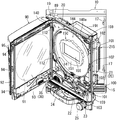
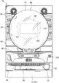
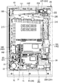
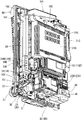
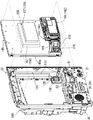
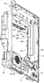
図1は遊技機の外枠の一側に本体枠が開かれその本体枠の一側にガラス扉が開かれた状態を示す斜視図である。図2は遊技機の前側全体を示す正面図である。図3は遊技機の後側全体を示す背面図である。図4は遊技機の本体枠に部材が組み付けられた状態を斜め左下方から示す斜視図である。図5は遊技機の本体枠と遊技盤とを分離して示す斜視図である。なお、説明の便宜上、遊技機において遊技者側を前、反対側を後として説明する。 FIG. 1 is a perspective view showing a state in which a main body frame is opened on one side of an outer frame of the gaming machine and a glass door is opened on one side of the main body frame. FIG. 2 is a front view showing the entire front side of the gaming machine. FIG. 3 is a rear view showing the entire rear side of the gaming machine. FIG. 4 is a perspective view showing the state in which the members are assembled to the main body frame of the gaming machine from obliquely lower left. FIG. 5 is a perspective view showing the main body frame of the gaming machine and the game board separately. For convenience of explanation, in the gaming machine, the player side will be described as the front and the opposite side as the back.
[遊技機の概要について]
図1〜図3に示すように、遊技機としてのパチンコ機は、外枠10、本体枠20、ガラス扉90、遊技盤140等を備えて構成されている。
外枠10は、上下左右の枠材によって縦長四角形の枠状に形成され、同外枠10の前側下部には、本体枠20の下面を受ける下受板15を有している。
外枠10の前面の片側には、本体枠開閉用ヒンジ機構19によって本体枠20が前方に開閉可能に装着されている。
[About the outline of gaming machines]
As shown in FIGS. 1 to 3, a pachinko machine as a gaming machine includes an
The
A
[本体枠について]
図1と図5に示すように、本体枠20は、前枠体21、遊技盤装着枠110及び機構装着体190を合成樹脂材によって一体成形することで構成されている。
本体枠20の前側に形成された前枠体21は、外枠10の前側の下受板15を除く外郭形状に対応する大きさの矩形枠状に形成されている。前枠体21の中央部には遊技盤装着枠110が形成され、その遊技盤装着枠110の後側に機構装着体190が形成されている。
[About the body frame]
As shown in FIGS. 1 and 5, the
The
[本体枠のスピーカボックス部について]
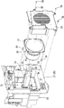
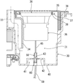
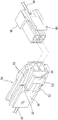
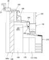
図5と図6に示すように、前枠体21の前側において、遊技盤装着枠110よりも下方に位置する前枠体21の前下部領域の一側(図5では左側)寄りには、スピーカボックス部30が一体に形成され、そのスピーカボックス部30の前側開口部には、同開口部を塞ぐようにしてスピーカ装着部材(スピーカカバー)35がビス等38によって装着されている。このスピーカ装着部材35は、多数のスリット状の貫通孔が貫設された前面板と、その前面板の後側周縁部に沿って後方に向けて突設された周壁部と、を備えて後方に開口する箱形状に形成され、そのスピーカ装着部材35の前面板の内面にはスピーカ(コーン型スピーカ)36がその前面フランジ37においてビス39等によって装着されている。
また、図6と図7に示すように、スピーカボックス部30は、前側が大きく後側に向けてしだいに小さくなった複数段の段差箱形状をなし、図9に示すように、スピーカボックス部30の後壁40とスピーカ36の前面フランジ37との間には音響室31が形成されている。
また、図6と図9に示すように、スピーカボックス部30の内壁面の一側部にはダクト部材34が装着され、これによって前端が前枠体21の前方に開口し後端部が音響室31に連通する音響通路33が形成されている。
[About the speaker box on the main unit frame]
As shown in FIGS. 5 and 6, on the front side of the
Further, as shown in FIGS. 6 and 7, the
Further, as shown in FIGS. 6 and 9, a
[スピーカボックス部の後壁のコネクタ接続について]
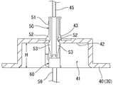
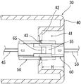
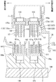
図7図8に示すように、スピーカボックス部30の後壁40の外面(後側)には、凹部41が形成され、その凹部41の底部42にはスピーカ36に対する配線用孔43が貫設されている。そして、図9に示すように、スピーカ36から延出されたスピーカ接続線45の端末コネクタ50が配線用孔43を塞ぐようにして同配線用孔43に弾性的に係合して取り付けられている。
図10〜図12に示すように、スピーカ接続線45の端末コネクタ50は、そのコネクタ本体51の上下の両外側面には、配線用孔43の上下両縁において底部42の内面に当接する当接片52と、底部42の外面に弾性的に係合する弾性係合部53とが形成されている。そして、図10に示すように、端末コネクタ50が底部42の内面側(音響室31側)から配線用孔43に押し込まれることで、底部42の内外両面が当接片52と弾性係合部53との間に狭持され、これによって、配線用孔43を塞ぐようにして端末コネクタ50が止着されるようになっている。
[Connecting the connector on the rear wall of the speaker box]
As shown in FIG. 7, a
As shown in FIGS. 10 to 12, the
また、図10〜図12に示すように、スピーカ接続線45の端末コネクタ50には、後述する副制御基板166に一端が接続された電源線59の他端の端末コネクタ60が差し込まれて電気的に接続される。この際、配線用孔43に対する弾性係合部53の係合力によって、配線用孔43にスピーカ接続線45の端末コネクタ50が係合保持されるため、同端末コネクタ50が音響室31側に外れることが防止されている。
As shown in FIGS. 10 to 12, the
前記したように、この実施例において、スピーカ接続線45の端末コネクタ50のコネクタ本体51と、電源線59の端末コネクタ60のコネクタ本体61との相互には、端末コネクタ60の差し込み動作によって弾性的に係合する雄形・雌形の抜け止め用係合部55、65がそれぞれ形成され、これら抜け止め用係合部55、65の係合力によって、スピーカ接続線45の端末コネクタ50から電源線59の端末コネクタ60が不測に外れることが防止されるようになっている。
また、配線用孔43を両端末コネクタ50、60によって塞ぐことができるため、音響室31側の音が漏れて音質低下をまねくという不具合を防止することができる。
As described above, in this embodiment, the connector
In addition, since the
また、この実施例において、図10と図11に示すように、スピーカボックス部30の後壁40に形成された凹部41の深さ寸法Hは、両端末コネクタ50、60が接続された状態で電源線59側の端末コネクタ60が凹部41の開口から後方に突出されることがない程度に設定されている。
これによって、両端末コネクタ50、60に対し異物が当たって外れたり、あるいは損傷されることが防止される。
Further, in this embodiment, as shown in FIGS. 10 and 11, the depth dimension H of the
This prevents foreign matter from hitting both
[本体枠の前枠体の前側下部の装備品について]
図1と図5に示すように、前枠体21前面の下部領域内の上側部分には、後に詳述する遊技盤140の発射通路に向けて球を導く発射レール22が傾斜状に装着され、その発射レール22の側方において本体枠20の前側から操作可能な電源スイッチS1が配置されている。
前枠体21前面の下部領域内の下側部分には、下部前面板23が装着されている。下部前面板23の前面の略中央部には、下皿24が設けられ、片側寄りには操作ハンドル25が設けられている(図1参照)。
[Equipment at the front lower part of the front frame body frame]
As shown in FIGS. 1 and 5, the upper part in the lower region of the front surface of the
A lower
[本体枠の前枠体の後側下部の装備品について]
図3と図4に示すように、前枠体21の後側において、遊技盤装着枠110よりも下方に位置する前枠体21の後下部領域の片側(図4に向かって左側)には、発射レール22の下傾端部の発射位置に送られた球を発射するための発射ハンマー73、その発射ハンマー73を作動する発射モータ72等が取付基板71に組み付けられてユニット化された発射装置ユニット70が装着されている。
[Equipment on the rear lower part of the front frame body frame]
As shown in FIGS. 3 and 4, on the rear side of the
また、図4に示すように、前枠体21の後下部領域の略中央部には、電源基板81を有する電源基板ボックス80が装着され、その電源基板ボックス80後側に重ね合わされた状態で払出制御基板86を有する払出制御基板ボックス85が前後に装着されている。
また、図3と図4に示すように、前枠体21の後下部領域の他側寄り部分(ヒンジ寄り部分)において、そのスピーカボックス部30の後段差部の凹み部分に装着された下皿用球誘導ケースの後側に位置してインタフェース基板231を収納しているインタフェース基板ボックス230が装着されている。
In addition, as shown in FIG. 4, a power
Further, as shown in FIGS. 3 and 4, the lower plate attached to the recessed portion of the rear step portion of the
[施錠装置について]
図1と図2に示すように、前枠体21のヒンジ機構と反対側に自由端側の後側には、外枠10に対し本体枠20を施錠する機能と、本体枠20に対しガラス扉90を施錠する機能とを兼ね備えた施錠装置100が装着されている。
すなわち、施錠装置100は、外枠10に設けられた閉止具17に係脱可能に係合して本体枠20を閉じ状態に施錠する上下複数の本体枠施錠フック101と、ガラス扉90の自由端側の後側に設けられた閉止具94に係脱可能に係合してガラス扉90を閉じ状態に施錠する上下複数の扉施錠フック102が前方に向けて突出されている。これら扉施錠フック102は、前枠体21の自由端寄り部分に貫設された貫通孔に挿通されてガラス扉90後側の閉止具94に係脱可能に臨んでいる。
[About locking device]
As shown in FIG. 1 and FIG. 2, the function of locking the
That is, the
また、施錠装置100はシリンダー錠103を備え、そのシリンダー錠103の前端部は、遊技機の前方から鍵を挿入されて解錠操作可能に、前枠体21及び下部前面板23を貫通してその下部前面板23の前面に露出されている(図2参照)。
そして、シリンダー錠103の鍵穴に鍵が挿入されて一方向に回動操作されることで本体枠施錠フック101と外枠10の閉止具17との係合が外れて本体枠20が解錠され、これとは逆方向に回動操作されることで、扉施錠フック102とガラス扉90の閉止具94との係合が外れてガラス扉90が解錠されるようになっている。
The
Then, the key is inserted into the keyhole of the
[ガラス扉について]
図1と図2に示すように、前枠体21の前面の片側には、その前枠体21の上端から下部前面板44の上縁にわたる部分を覆うようにしてガラス扉90が扉開閉用ヒンジ機構89によって前方に開閉可能に装着されている。ガラス扉90のヒンジ機構89と反対側に自由端側の後側には、施錠装置100の扉施錠フック102に係脱可能に係合してガラス扉90を閉じ状態に施錠する閉止具94が設けられている。
また、ガラス扉90の略中央部には、後に詳述する遊技盤140の遊技領域144を前方から透視可能な略円形の開口窓91が形成されている。また、ガラス扉90の後側には開口窓91よりも大きな矩形枠状をなす窓枠92が設けられ、その窓枠92にはガラス板、透明樹脂板等の透明板93が装着されている。
また、ガラス扉90の前面の略全体は、ランプ等が内設された前面装飾部材95によって装飾され、同ガラス扉90の前面の下部には上皿96が形成されている(図2参照)。
[About glass doors]
As shown in FIGS. 1 and 2, a
In addition, a substantially
Further, substantially the entire front surface of the
[本体枠の機構装着体について]
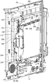
図3と図4に示すように、本体枠20の機構装着体190の上部後側には、島設備から供給される多数の球が貯留可能な球タンク165、その球タンク165の下方に連通するタンクレール171とが配設されている。
また、本体枠20の機構装着体190の片側(図に向かって右側)寄りの上下方向にはユニット化された球払出装置210が装着されている。
[About the body mounting mechanism]
As shown in FIG. 3 and FIG. 4, on the upper rear side of the
Further, a unitized
[外部端子基板と分電基板の配置について]
図3と図24に示すように、機構装着体190の後上隅部(ヒンジ寄り側)には、第1基板装着部220と第2基板装着部225とが段差状をなして形成され、下段の第1基板装着部220には外部端子基板222が装着され、上段の第2基板装着部225には分電基板226が分電基板ボックス227に覆われた状態で装着されている。
図23に示すように、後に詳述する遊技盤140の後側に配置された図柄制御基板ボックス146及び主制御基板ボックス161の後端部は機構装着体190の中央部に開口された窓開口部に向けて突出している。そして、機構装着体190の窓開口部の一側壁を構成する側壁部と他側壁を構成する払出装置装着部200の片側壁との間には、後カバー体215がその一側を支点として開閉可能に装着されている。
そして、遊技盤140後側の図柄制御基板ボックス146全体及び主制御基板ボックス151の上部が後カバー体215によって覆われるようになっている(図4参照)。
[Disposition of external terminal board and distribution board]
As shown in FIGS. 3 and 24, the first
As shown in FIG. 23, the rear ends of the symbol control board box 146 and the main
The entire symbol control board box 146 on the rear side of the
[本体枠側の回路基板と遊技盤側の回路基板の接続について]
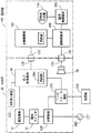
図25のブロック図で示すように、本体枠20側においては、交流電源ACから供給される交流電力が、分電基板226、電源スイッチS1を経て電源基板81に流れ、ここで直流電力に変換されて払出制御基板86に供給される。
また、払出制御基板86は、球を払い出す数を記憶するRAM86aを備え、主制御基板162から送信される払出用信号に従って球を払い出す制御(球払出装置210のモータの作動制御)を行うようになっている。
また、交流電源ACから供給される交流電力は、分電基板226においてインタフェース基板231にも分配供給される。
インタフェース基板231は、球貸機235と払出制御基板86との間に介在され、球貸に関する信号を球貸機235と払出制御基板86との間で送受信可能に電気的に接続するようになっている。
また、払出制御基板86には、各種検出器からの信号や主制御基板162からの信号が伝達される。これに基づいて払出制御基板86から例えば、大当たり信号、扉開放信号、賞球信号等の信号が外部端子基板222に送信され、その外部端子基板222の各外部出力端子から前記した大当たり信号、扉開放信号、賞球信号等の信号がホールコンピュータに伝達されるようになっている。
[Connection between the circuit board on the main body frame side and the circuit board on the game board side]
As shown in the block diagram of FIG. 25, on the
Further, the
The AC power supplied from the AC power supply AC is also distributed and supplied to the
The
Further, signals from various detectors and signals from the
また、後に詳述する遊技盤140の後側に配置された主制御基板162は遊技の進行を制御し、副制御基板166は周辺機器を制御する。すなわち主制御基板162からの遊技に関する信号を受けた副制御基板166は、図柄制御基板156を介して図柄表示装置155に表示を行う。さらに、副制御基板166は、スピーカ36を作動制御する。
また、図柄制御基板156は、遊技用信号を表示用信号に変換して図柄表示装置155に伝達する。図柄表示装置155には大当たりの抽選図柄が変動表示可能となっている。
Further, a
In addition, the
[本体枠の配線構造について]
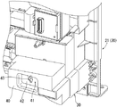
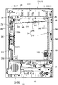
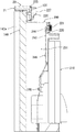
図20〜図23に示すように、遊技盤装着枠110に装着された遊技盤140の後側周辺部のうちの少なくとも左右両側部と機構装着体190の前壁部との間には、第1、第2の配線空間241、251が左右に分離して設けられている。そして、第1配線空間241には電源線240が配線され、第2配線空間251には各種信号に対応する複数本の信号線250が配線されている。
電源線240は、本体枠20の機構装着体190の後側上隅部に配置された分電基板226と、同本体枠20の前枠体21の後側下部に配置された電源基板(この実施例では電源スイッチS1)81とを電気的に接続するものである。
また、信号線250は、本体枠20の機構装着体190の後側上隅部に配置された外部端子基板222と、同本体枠20の前枠体21の後側下部に配置された払出制御基板86とを電気的に接続するものである。
[Wiring structure of main frame]
As shown in FIGS. 20 to 23, there is a gap between at least the left and right sides of the rear peripheral portion of the
The
Further, the
この実施例おいて、第1配線空間241は、分電基板226と電源基板(この実施例では電源スイッチS1)81との左右方向の距離寸法に対応する横空間部242と、分電基板226と電源基板(この実施例では電源スイッチS1)81との上下方向の距離寸法に対応する縦空間部245とを備えて略逆L字状をなしている。
また、第1配線空間241の横空間部242に対応する機構装着体190の前壁部上部には、略L字状をなして突出しかつ先端部に抜止爪を有する複数の保持片243が左右方向に所定間隔をもって配設されている。
また、第1配線空間241の縦空間部245に対応する機構装着体190の前壁部の右側上部から下部において、略コの字状をなして突出する複数の保持片245が上下方向に所定間隔をもって突設されている。
In this embodiment, the
In addition, a plurality of holding
In addition, a plurality of holding
また、この実施例において、図21に示すように、横空間部242に対応する位置に配置された複数の保持片243は、向きを交互に上下逆向きに形成され、これによって、複数の保持片243に対し電源線240の挿入向きを上方と下方とに交互に換えて掛け渡すことによってその電源線240の挿通作業が容易に行なうことができるとともに、複数の保持片243に掛け渡された電源線240の上下方向への移動が規制され、電源線240の外れが防止されるようになっている。
Further, in this embodiment, as shown in FIG. 21, the plurality of holding
第2配線空間251は、外部端子基板222と払出制御基板86との上下方向の距離寸法に対応して機構装着体190の左側の上部から下部にわたって形成されている。
また、第2配線空間251に対応する機構装着体190の前壁部左前には、略L字状をなして突出しかつ先端部に抜止爪を有する複数の保持片246が適宜姿勢でかつ上下方向に所定間隔をもって配設されている。
The
In addition, a plurality of holding
[本体枠の遊技盤装着枠及び遊技盤について]
図1と図5に示すように、本体枠20の遊技盤装着枠110は、前枠体21の中央部後側に設けられかつ遊技盤140が前方から着脱交換可能に嵌込まれて装着されるようになっている。
すなわち、この実施例において、遊技盤装着枠110の奥側(後側)の枠部内周には遊技盤140の後側の周縁部を受け止める後面受け部111が形成されている。
また、遊技盤装着枠110の一側内壁面の上下部2箇所には、後面受け部111との間に遊技盤140の一側部が差し込み可能な間隔を隔てて前面押え部112が形成されている。
[About the game board mounting frame and game board of the main body frame]
As shown in FIG. 1 and FIG. 5, the game
That is, in this embodiment, a
In addition,
図1と図5に示すように、遊技盤140は、遊技盤装着枠110の前方から嵌込まれる大きさの略四角板状に形成されている。遊技盤140の盤面(前面)には、外レールと内レールとを備えた案内レール141が設けられ、その案内レール141の内側に遊技領域144が区画形成されている。
また、遊技盤140の前面には、その案内レール141の外側領域において、合成樹脂製の前構成部材140aが装着されている。
As shown in FIGS. 1 and 5, the
In addition, a
また、遊技盤140には、その遊技領域144内において、遊技に関する役物装置、例えば、センタ役物と呼ばれる役物装置150、入賞装置、風車器、誘導釘、ランプ装飾部材等の各種の装備品が配設されている。
また、役物装置150の役物本体151には、その略中央部に開口窓が形成され、役物本体151の後側には、その開口窓に臨んで図柄表示装置(例えば、液晶表示器、EL表示器,プラズマ表示器,CRT等)155が装着されている。
また、図柄表示装置155の後側には、図柄制御基板156が収納された図柄基板ボックス157が装着されている。(図5参照)。
Further, the
The
In addition, on the rear side of the
また、図1に示すように、遊技盤140前面の前構成部材140aの右側寄りの上下2箇所には、遊技盤装着枠110の係止部に対応する位置においてロック部材159がピンと左右方向の長孔によって回動操作可能に装着されている。
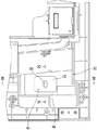
そして、遊技盤140(前構成部材140aを含む)は、その一側(左側)を奥、反対側(右側)を手前にした斜めの状態で、その一側部(左側部が)が遊技盤装着枠110の後面受け部111と前面押え部112との間に差し込まれる(図18参照)。そして、前面押え部112と遊技盤140の一側部との係合部を支点として遊技盤140が遊技盤装着枠110に沿う装着位置まで回動される。ここで、ロック部材159の先端のロック部が遊技盤装着枠110の係止部に差し込まれて係合されることで遊技盤装着枠110に遊技盤140が着脱交換可能に装着されるようになっている。
Further, as shown in FIG. 1, the
The game board 140 (including the
図5に示すように、遊技盤140の後側下部には、その中央部から下部にわたる部分において、各種入賞装置に流入した球を受けかつその球を所定位置まで導く集合樋としての機能とボックス装着部としての機能を兼ね備えたボックス装着台160が設けられている。このボックス装着台160の後側には、副制御基板166が収納された副制御基板ボックス165が装着され、その副制御基板ボックス165の後側に重ね合わされた状態で、主制御基板162が収納された主制御基板ボックス161が装着されている。
さらに、遊技盤140の後側に対しボックス装着台160、副制御基板ボックス165及び主制御基板ボックス161がそれぞれ装着された状態において、本体枠20の遊技盤装着枠110の前方からその遊技盤装着枠110内に遊技盤140を嵌込んで装着できるように、遊技盤140の外郭より外側にはみ出すことなくボックス装着台160、副制御基板ボックス165及び主制御基板ボックス161が配置されている。
As shown in FIG. 5, in the lower part on the back side of the
Further, in a state where the
[本体枠と遊技盤のコネクタ接続について]
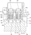
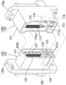
図5と図18に示すように、本体枠20の前側と、遊技盤140の後側との間には、遊技盤装着枠110に対し遊技盤140を装着するときの回動動作に伴って電気的に接続される本体枠側第1、第2のコネクタ120、130と遊技盤側第1、第2のコネクタ170、180とがそれぞれ配設されている。
この実施例において、図18と図19に示すように、遊技盤140を装着するときの回動支点と反対側の自由端部に位置する本体枠20の遊技盤装着枠110の右下部近傍に設けられたコネクタ装着部に本体側第1、第2のコネクタ120、130が、その各コネクタベース120a、130aにおいて、嵌込みによって位置決めされた状態で左右隣接して固定されている。
また、遊技盤140の後側の自由端部寄り下部に設けられたコネクタ装着部に遊技盤側第1、第2のコネクタ170、180が、その各コネクタベース170a、180aにおいて、嵌込みによって位置決めされた状態で左右隣接して固定されている。
また、対をなす第1コネクタ120、170は自由端側に位置し、対をなす第2コネクタ130、180は回動支点側に隣接して配置されている。
また、
[Connecting the main body frame and game board connector]
As shown in FIG. 5 and FIG. 18, between the front side of the
In this embodiment, as shown in FIGS. 18 and 19, in the vicinity of the lower right portion of the game
In addition, the first and
The paired
Also,
この実施例において、図25に示すように、対をなす第1コネクタ120、170は、本体枠20側の払出制御基板(制御基板)86と、遊技盤140側の主制御基板(制御基板)162とを電気的に接続する。
また、対をなす第1コネクタ120、170によって各種の信号線が電気的に接続された状態において、例えば、遊技盤140側の主制御基板(制御基板)162から出力される賞球払出信号、外部出力用情報信号(大当たり信号、賞球数信号等)等の信号が本体枠20側の払出制御基板(制御基板)86に伝達される。また、本体枠20側の払出制御基板(制御基板)86から出力されRAM消去信号等の信号が遊技盤140側の主制御基板(制御基板)162に伝達されるようになっている。
また、対をなす第2コネクタ130、180によって各種の信号線が電気的に接続された状態において、例えば、遊技盤140側の副制御基板1(制御基板)66から出力される作動制御信号が本体枠20側の電気機器、(例えば、スピーカ36)に伝達されるようになっている。
In this embodiment, as shown in FIG. 25, a pair of
In addition, in a state where various signal lines are electrically connected by the paired
Further, in the state where various signal lines are electrically connected by the paired
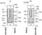
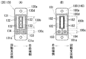
図14〜図16に示すように、本体枠側第1コネクタ120において、そのコネクタベース120a上には、第1の端子配設領域120bと第2の端子配設領域120cとが上下に隣接(区分け)して設けられ上下方向に長い縦形状をなしている。
すなわち、本体枠側第1コネクタ120のコネクタベース120a上の第1の端子配設領域120bには、縦長角筒状の端子保持筒120dが一体に突設され、その端子保持筒120dの両外側面には、遊技に関連する信号(例えば、DC5V)を伝達するための各種の信号線に対応する複数(多数)の信号端子(信号線用雄型端子)122が縦方向に配列されている。
また、図15と図16の(A)に示すように、本体枠側第1コネクタ120のコネクタベース120a上の第2の端子配設領域120cには、本体枠20側から遊技盤140側に対し複数の異なる電圧(例えば、DC34V、DC12V)の電源を供給する複数の電源線に対応する電源端子(電源線用雄型プラス端子)123、125及びグランド線に対応するグランド端子(グランド線用雄型端子)124、126がそれぞれ所定間隔を隔てて突出された状態で配置されている。
また、本体枠側第1コネクタ120のコネクタベース120a上には、複数の信号端子(信号線用雄型端子)122、電源端子(電源線用雄型プラス端子)123、125及びグランド端子(グランド線用雄型端子)124、126を保護するために、第1、第2の端子配設領域120b、120cを外側から覆って取り囲む縦長箱形状の周壁体121が各端子よりも高い位置まで突設されている。
さらに、第2の端子配設領域120cにおいては、電源端子(電源線用雄型プラス端子)123、125及びグランド端子(グランド線用雄型端子)124、126の計4本の端子をそれぞれ個別に取り囲むために、第2の端子配設領域120cに対応する周壁体121の部分には、略十字状の溝を隔てた4つの区画壁121aが形成されている。
As shown in FIGS. 14-16, in the main body frame
That is, the first
Further, as shown in FIG. 15 and FIG. 16A, the second
On the
Furthermore, in the second
図15と図16の(B)に示すように、遊技盤140を装着するときの回動動作に伴って電気的に接続される遊技盤側第1コネクタ170において、そのコネクタベース170a上には、第1の端子配設領域170bと第2の端子配設領域170cとが上下に隣接(区分け)して設けられ上下方向に長い縦形状をなしている。
遊技盤側第1コネクタ170のコネクタベース170a上の第1の端子配設領域170bには、本体枠側の端子保持筒170dが挿入される縦長角筒状の端子保持筒170dが一体に突設され、その端子保持筒170dの両内壁面には、複数(多数)の信号端子(信号線用雄型端子)122に対応する複数(多数)の信号端子(信号線用雌型端子)172が縦方向に配列されている。
また、遊技盤側第1コネクタ170のコネクタベース170a上の第2の端子配設領域170cには、電源端子(電源線用雄型プラス端子)123、125及びグランド線に対応するグランド端子(グランド線用雄型端子)124、126にそれぞれ対応する電源端子(電源線用雌型プラス端子)173、175及びグランド端子(グランド線用雌型端子)174、176がそれぞれ所定間隔を隔てて突出された状態で配置されている。
また、遊技盤側第1コネクタ170のコネクタベース170a上には、複数の信号端子(信号線用雄型端子)172、電源端子(電源線用雌型プラス端子)173、175及びグランド端子(グランド線用雌型端子)174、176を保護するために、第1、第2の端子配設領域170b、170cを外側から覆って取り囲む縦長箱形状の周壁体171が各端子よりも高い位置まで突設されている。
さらに、遊技盤側第1コネクタ170の周壁体171の内部の第2の端子配設領域170cにおいて、電源端子(電源線用雌型プラス端子)173、175及びグランド端子(グランド線用雌型グランド端子)174、176を区画しかつ本体枠側第1コネクタ120の略十字状の溝に差し込まれる略十字状の仕切壁171aが形成されている。
As shown in FIG. 15 and FIG. 16 (B), in the game board side
In the first
In addition, the second
Further, on the
Further, in the second
すなわち、この実施例においては、遊技盤側第1コネクタ170の周壁体171が、本体枠側第1コネクタ120の周壁体121の外側に嵌込まれる大きさに形成されている。そして、対をなす第1コネクタ120、170の両周壁体121、171が相互に嵌込まれることで、対をなす第1コネクタ120、170の各複数の信号端子(信号線用雄型・雌型の各端子)122と172、電源端子(電源線用雄型・雌型の各プラス端子)123、125と173、175及びグランド端子(グランド線用雄型・雌型の端子)124、126と174、176がそれぞれ接続案内されるようになっている。
That is, in this embodiment, the
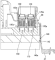
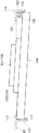
また、遊技盤140の一側部を支点とする遊技盤140の装着時の回動動作に伴って、本体枠側第1のコネクタ120と遊技盤側第1コネクタ170とがそれぞれ差し込まれる際、まず、グランド端子(グランド線用雄型・雌型の端子)124、126と174、176が接続され、その後、電源端子(電源線用雄型・雌型の各プラス端子)123、125と173、175が接続されるように、図19に示すように、グランド端子(グランド線用雄型・雌型の端子)124、126と174、176が遊技盤140の回動支点側に配置され、電源端子(電源線用雄型・雌型の各プラス端子)123、125と173、175が遊技盤140の回動自由端側に配置されている。
また、この実施例において、図19に示すように、グランド線用雄型端子をなすグランド端子124、126と、電源線用雄型プラス端子をなす電源端子123、125において、雄型のグランド端子124、126は、雄型の電源端子173、175よりも長さL1に相当する分だけ長く形成されている。
また、雄型のグランド端子124、126と雄型の電源線用雄型プラス端子123、125との長さは略同じとし、雌型のグランド端子174、176を雌型の電源端子173、175よりも適宜に長く形成してもよい。
In addition, when the main body frame side
Further, in this embodiment, as shown in FIG. 19, in the
The lengths of the
一方、対をなす第2コネクタ130、180においても、前記した対をなす第1コネクタ120、170と略同様にして構成されている。
すなわち、図17の(A)に示すように、本体枠側第2コネクタ130において、そのコネクタベース130a上には、第1の端子配設領域130bと第2の端子配設領域130cとが上下に隣接(区分け)して設けられ上下方向に長い縦形状をなしている。
本体枠側第2コネクタ130のコネクタベース130a上の第1の端子配設領域130bには、縦長角筒状の端子保持筒130dが一体に突設され、その端子保持筒130dの両外側面には、遊技に関連する信号(例えば、DC5V)を伝達するための各種の信号線に対応する複数(多数)の信号端子(信号線用雄型端子)132が縦方向に配列されている。
また、本体枠側第2コネクタ130のコネクタベース130a上の第2の端子配設領域130cには、本体枠20側から遊技盤140側に対し所定の電圧(例えば、DC34V)の電源を供給する電源線に対応する電源端子(電源線用雄型プラス端子)133及びグランド線に対応するグランド端子(グランド線用雄型端子)134が突出された状態で配置されている。
また、本体枠側第2コネクタ130のコネクタベース130a上には、複数の信号端子(信号線用雄型端子)132、電源端子(電源線用雄型プラス端子)133及びグランド端子(グランド線用雄型端子)134を保護するために、第1、第2の端子配設領域130b、130cを外側から覆って取り囲む縦長箱形状の周壁体131が各端子よりも高い位置まで突設されている。
さらに、第2の端子配設領域130cにおいては、電源端子(電源線用雄型プラス端子)133及びグランド端子(グランド線用雄型端子)134を個別に取り囲むために、第2の端子配設領域130cに対応する周壁体131の部分には溝を隔てた区画壁131aが形成されている。
On the other hand, the
That is, as shown in FIG. 17A, in the main body frame side
In the first
In addition, a power of a predetermined voltage (for example, DC34V) is supplied from the
Further, on the
Further, in the second
図17の(B)に示すように、遊技盤側第2コネクタ180において、そのコネクタベース180a上には、第1の端子配設領域180bと第2の端子配設領域180cとが上下に隣接(区分け)して設けられ上下方向に長い縦形状をなしている。
遊技盤側第2コネクタ180のコネクタベース180a上の第1の端子配設領域180bには、本体枠側の端子保持筒130dが挿入される縦長角筒状の端子保持筒1180dが一体に突設され、その端子保持筒1180dの両内壁面には、複数(多数)の信号端子(信号線用雌型端子)182が縦方向に配列されている。
また、遊技盤側第2コネクタ180のコネクタベース180a上の第2の端子配設領域180cには、電源端子(電源線用雄型プラス端子)133及びグランド線に対応するグランド端子(グランド線用雄型端子)134にそれぞれ対応する電源端子(電源線用雌型プラス端子)183及びグランド端子(グランド線用雌型端子)184が突出された状態で配置されている。
また、遊技盤側第2コネクタ180のコネクタベース180a上には、複数の信号端子(信号線用雄型端子)182、電源端子(電源線用雌型プラス端子)183及びグランド端子(グランド線用雌型端子)184を保護するために、第1、第2の端子配設領域180b、180cを外側から覆って取り囲む縦長箱形状の周壁体181が各端子よりも高い位置まで突設されている。
さらに、遊技盤側第2コネクタ180の周壁体181の内部の第2の端子配設領域180cにおいて、電源端子(電源線用雌型プラス端子)183及びグランド端子(グランド線用雌型グランド端子)184を区画しかつ本体枠側第2コネクタ130の溝に差し込まれる仕切壁181aが形成されている。
As shown in FIG. 17B, in the game board side
In the first
The second
Further, on the
Furthermore, in the second
また、遊技盤側第2コネクタ180の周壁体181は、本体枠側第2コネクタ130の周壁体131の外側に嵌込まれる大きさに形成されている。そして、対をなす第2コネクタ130、180の両周壁体131、181が相互に嵌込まれることで、対をなす第2コネクタ130、180の各複数の信号端子(信号線用雄型・雌型の各端子)132と182、電源端子(電源線用雄型・雌型の各プラス端子)133と183及びグランド端子(グランド線用雄型・雌型の端子)134と184がそれぞれ接続案内されるようになっている。
Further, the
また、遊技盤140の一側部を支点とする遊技盤140の装着時の回動動作に伴って、本体枠側第2コネクタ130と遊技盤側第2コネクタ180とがそれぞれ差し込まれる際、まず、グランド端子(グランド線用雄型・雌型の端子)134と184が接続され、その後、電源端子(電源線用雄型・雌型の各プラス端子)133と183が接続されるように、図17と図19に示すように、グランド端子(グランド線用雄型・雌型の端子)134と184が遊技盤140の回動支点側に配置され、電源端子(電源線用雄型・雌型の各プラス端子)133と183が遊技盤140の回動自由端側に配置されている。
また、この実施例において、図19に示すように、グランド線用雄型端子をなすグランド端子134と、電源線用雄型プラス端子をなす電源端子133において、雄型のグランド端子134は、雄型の電源端子133よりも長さL2に相当する分だけ長く形成されている。
また、雄型のグランド端子134と雄型の電源線用雄型プラス端子133との長さは略同じとし、雌型のグランド端子184を雌型の電源端子183よりも適宜に長く形成してもよい。
Further, when the main body frame side
Further, in this embodiment, as shown in FIG. 19, in the
The lengths of the
[この実施例に係る遊技機の作用効果について]
上述したように構成されるこの実施例に係る遊技機において、本体枠20の遊技盤装着枠110に対し遊技盤140を装着する場合、まず、図18に示すように、遊技盤140(前構成部材140aを含む)は、その一側(左側)を奥、反対側(右側)を手前にした斜めの状態で、その一側部(左側部が)が遊技盤装着枠110の後面受け部111と前面押え部112との間に差し込まれる。そして、前面押え部112と遊技盤140の一側部との係合部を支点として遊技盤140が遊技盤装着枠110に沿う装着位置まで回動される。ここで、ロック部材159の先端のロック部が遊技盤装着枠110の係止部に差し込まれて係合されることで遊技盤装着枠110に遊技盤140が着脱交換可能に装着される(図1参照)。
[About the effects of the gaming machine according to this embodiment]
In the gaming machine according to this embodiment configured as described above, when the
前記したように、遊技盤140の一側部の係合部を支点とする遊技盤140の装着時の回動動作に伴って、本体枠20の前側に配設された本体枠側第1、第2のコネクタ120、130と、遊技盤140の後側に配設された遊技盤側第1、第2のコネクタ170、180とがそれぞれ接続される。
また、前記とは逆の手順で操作することで、本体枠20の遊技盤装着枠110に対し遊技盤140を取り外すことができる共に、本体枠側第1、第2のコネクタ120、130と遊技盤側第1、第2のコネクタ170、180とをそれぞれ離脱させることができる。
このため、本体枠20に対し遊技盤140を着脱交換する度毎に、信号線や電源線を外したりあるいは接続する煩わしい手間を解消することができる。
As described above, the main body frame side first disposed on the front side of the
Further, by operating in the reverse procedure, the
For this reason, every time the
この実施例において、本体枠20の前側と遊技盤140の後側に配設されて対をなす第1コネクタ120、170は、第1、第2の端子配設領域120b、120c、170b、170cを上下に隣接(区分け)して備えて縦長状をなしている。そして、第1コネクタ120、170の第1の端子配設領域120b、170bには、複数(多数)の信号端子122が縦方向に二列をなして配列され、第2の端子配設領域120c、170cには電源端子123、125、173、175と、グランド端子124、126、174、176が縦方向に二列をなして配列されている。このため、各端子の左右方向の距離寸法を小さくすることができ、遊技盤140の装着時の回動動作に伴って、本体枠側第1コネクタ120と、遊技盤側第1コネクタ170とが円滑に嵌込まれる。
すなわち、対をなす第1コネクタ120、170が左右方向に長い横長状に形成された場合には、左右両端の端子の左右方向の距離寸法が大きくなり、遊技盤140の装着時の回動動作に伴って、本体枠側第1コネクタ120と、遊技盤側第1コネクタ170とを嵌込こむことが困難となる場合があるが、このような不具合を防止することができる。
In this embodiment, the
That is, when the paired
また、対をなす第2コネクタ130、180においても、対をなす第1コネクタ120、170と略同様にして、第1、第2の端子配設領域130b、130c、180b、180cを上下に隣接(区分け)して備えて縦長状をなしているため、各端子の左右方向の距離寸法を小さくすることができ、遊技盤140の装着時の回動動作に伴って、本体枠側第2コネクタ130と、遊技盤側第2コネクタ170とが円滑に嵌込まれる。
このため、
Also, the
For this reason,
また、第1コネクタ120、170の第2の端子配設領域120c、170cに配設された電源端子123、125、173、175と、グランド端子124、126、174、176のうち、グランド端子124、126、174、176は遊技盤140の回動支点側に配置され、電源端子123、125、173、175は遊技盤140の回動自由端側に配置されている。
このため、遊技盤140の回動動作に伴って、本体枠側第1コネクタ120と遊技盤側第1コネクタ170とが接続されるときには、グランド端子124、126、174、176が電源端子123、125、173、175よりも先に接続される。
したがって、遊技機の電源がONの状態であることを気づかないで遊技盤140を脱着交換した場合においても、設計経路とは異なる経路で電流が流れることを防止することができ、回路基板としての主制御基板162上に配設されたICチップ、トランジスタ等の電子部品が過電流によって破損されることを防止することができる。
Of the
For this reason, when the main body frame side
Therefore, even when the
また、対をなす第2コネクタ130、180においても、対をなす第1コネクタ120、170と略同様にして、グランド端子134(184)は遊技盤140の回動支点側に配置され、電源端子133(183)は遊技盤140の回動自由端側に配置されているため、遊技機の電源がONの状態であることを気づかないで遊技盤140を脱着交換した場合においても、設計経路とは異なる経路で電流が流れることを防止することができる。
Also, in the
また、この実施例において、対をなす第1コネクタ120、170のうち、少なくとも一方のコネクタ(例えば、本体枠側第1コネクタ120)において、グランド端子124、126は、電源端子123、125よりも所定長さL1だけ長く形成されている。このため、一方のコネクタ(例えば、本体枠側第1コネクタ120)のグランド端子124、126が電源端子123、125よりも長く形成されている分だけ、他方のコネクタ(遊技盤側第1コネクタ170)のグランド端子174、176に先に(早く)接続される。このため、一方のコネクタ(例えば、本体枠側第1コネクタ120)の電源端子123、125が他方のコネクタ(遊技盤側第1コネクタ170)の電源端子173、175に先に接続されることをより一層確実に防止することができる。
In this embodiment, in at least one of the paired
また、対をなす第2コネクタ130、130においても、対をなす第1コネクタ120、170と略同様にして、少なくとも一方のコネクタ(例えば、本体枠側第2コネクタ130)において、グランド端子134は、電源端子133よりも所定長さL2だけ長く形成されている。このため、一方のコネクタ(例えば、本体枠側第2コネクタ130)のグランド端子134が電源端子133よりも長く形成されている分だけ、他方のコネクタ(遊技盤側第2コネクタ180)のグランド端子184に先に(早く)接続される。このため、一方のコネクタ(例えば、本体枠側第2コネクタ130)の電源端子133が他方のコネクタ(遊技盤側第2コネクタ180)の電源端子183に先に接続されることをより一層確実に防止することができる。
Also, in the
また、対をなす第1コネクタ120、170において、本体枠側第1コネクタ120及び遊技盤側第1コネクタ170にそれぞれ形成された周壁体121、171によって、それぞれの第1、第2の端子配設領域120b、120c、17b、17cを外側から覆って取り囲むことで、第1の端子配設領域120b、170bに配設された複数の信号端子122、172及び第2の端子配設領域120c、170bに配設された電源端子123、125、173、175及びグランド端子124、126、174、176を保護することができる。このため、本体枠20の遊技盤装着枠110から遊技盤140が取り外された状態において、本体枠側第1コネクタ120及び遊技盤側第1コネクタ170の第1、第2の端子配設領域、120b、120c、170b、170cに配設された複数の信号端子122、172、電源端子123、125、173、175及びグランド端子124、126、174、176に対し異物が不測に当たって損傷されることを防止することができる。
Also, in the
また、遊技盤側第1コネクタ170の周壁体171が外側、本体枠側第1コネクタ120の周壁体121が内側に位置して相互に嵌込まれることで、本体枠側第1コネクタ120の複数の信号端子122、電源端子123、125及びグランド端子124、126と、遊技盤側第1コネクタ170の複数の信号端子172、電源端子173、175及びグランド端子174、176とが接続案内される。このため、各端子の接続不良を良好に防止することができる。
In addition, the
また、対をなす第2コネクタ130、180においても、対をなす第1コネクタ120、170と略同様にして、本体枠側第2コネクタ130及び遊技盤側第2コネクタ180にそれぞれ形成された周壁体131、181によって、それぞれの第1、第2の端子配設領域130b、130c、180b、180cを外側から覆って取り囲むことで、第1の端子配設領域130b、180bに配設された複数の信号端子132、182及び第2の端子配設領域130c、180cに配設された電源端子133、183及びグランド端子134、184を保護することができ、複数の信号端子132、182、電源端子133、183及びグランド端子134、184に対し異物が不測に当たって損傷されることを防止することができる。
さらに、遊技盤側第2コネクタ180の周壁体181が外側、本体枠側第2コネクタ130の周壁体121が内側に位置して相互に嵌込まれることで、本体枠側第2コネクタ130の複数の信号端子132、電源端子133及びグランド端子134と、遊技盤側第2コネクタ180の複数の信号端子182、電源端子183及びグランド端子184とが接続案内される。このため、各端子の接続不良を良好に防止することができる。
Further, in the
Furthermore, the
また、この実施例においては、本体枠20の前側と、遊技盤140の後側との間には、遊技盤装着枠110に対し遊技盤140を装着するときの回動動作に伴って電気的に接続される複数対の第1コネクタ120、170と第2コネクタ130、180とがそれぞれ配設されている。
そして、対をなす第1コネクタ120、170は、本体枠20側の払出制御基板(制御基板)86と、遊技盤140側の主制御基板(制御基板)162とを電気的に接続し、対をなす第2コネクタ130、180は、本体枠20側の電気機器(例えば、スピーカ36)と、遊技盤140側の副制御基板1(制御基板)66とを電気的に接続する。
このようにして、複数対の第1、第2のコネクタ120、170及び130、180によって本体枠20側と遊技盤140側を電気的に接続することで、小型のコネクタを用いることができ、コネクタの配置設計の自由度を高めることができる。
すなわち、複数対のコネクタに分散して配置された多数の信号端子、電源端子、グランド端子を、一対のコネクタに集約して配置すると、コネクタが大型化し、配置スペースの確保が困難となる場合があるが、複数対の小型のコネクタを用いることで、これら複数対のコネクタを並列(横方向に隣接して)配置したり、あるいは直列(縦方向に隣接して)配置したり、あるいは縦横方向に所定距離を隔てて配置することが可能となり、コネクタの配置設計の自由度を高めることができる。
Further, in this embodiment, between the front side of the
The pair of
In this way, a small connector can be used by electrically connecting the
In other words, if a large number of signal terminals, power supply terminals, and ground terminals that are distributed over a plurality of pairs of connectors are aggregated and arranged in a pair of connectors, the size of the connector may increase and it may be difficult to secure an arrangement space. However, by using multiple pairs of small connectors, these multiple pairs of connectors can be arranged in parallel (adjacent in the horizontal direction), in series (adjacent in the vertical direction), or in the vertical and horizontal directions. It is possible to arrange them at a predetermined distance from each other, and the degree of freedom in designing the arrangement of the connectors can be increased.
[この発明の他の実施例について]
なお、この発明は前記実施例に限定するものではない。
例えば、前記実施例においては、本体枠20の前側と、遊技盤140の後側との相互に、遊技盤装着枠110に対し遊技盤140を装着するときの回動動作に伴って電気的に接続される複数対の第1コネクタ120、170と第2コネクタ130、180とがそれぞれ配設される場合を例示したが、本体枠20の前側と、遊技盤140の後側との相互に、複数(多数)の信号端子、電源端子、グランド端子を有する一対のコネクタを配設した場合においてもこの発明を実施することができる。
また、電圧が高低異なる複数の電源端子、グランド端子及び複数(多数)の信号端子が設けられた対のコネクタにおいて、グランド端子、信号端子、低い電源端子及び高い電圧の電源端子の順に接続されるように、グランド端子を最も長くし、次に信号端子、その次に低い電源端子、最短を高い電圧の電源端子としてこれら各端子の長さを設定してもこの発明を実施することができる。
また、前記実施例においては、本体枠20の遊技盤装着枠110の後面受け部111と前面押え部112との間に、遊技盤140の一側部を斜めの状態で差し込み、前面押え部112と遊技盤140の一側部との係合部を支点として遊技盤140が遊技盤装着枠110に沿う装着位置まで回動されるように構成したが、例えば、本体枠20の遊技盤装着枠110の一側部に離脱可能なヒンジ機構によって遊技盤140を回動可能に支持することで、遊技盤装着枠110に対し遊技盤140を着脱交換可能に構成してもこの発明を実施することができる。
また、前記実施例においては、前枠体21、遊技盤装着枠110及び機構装着体190が合成樹脂材によって一体成形されることで本体枠20が構成される場合を例示したが、前枠体21、遊技盤装着枠110及び機構装着体190がそれぞれ別個に形成され、これら各部材が相互に組み付けられる構造であってもこの発明を実施することができる。
[Other Embodiments of the Invention]
In addition, this invention is not limited to the said Example.
For example, in the above-described embodiment, the front side of the
Further, in a pair of connectors provided with a plurality of power terminals, ground terminals, and a plurality (large number) of signal terminals having different voltages, the ground terminals, the signal terminals, the low power terminals, and the high voltage power terminals are connected in this order. As described above, the present invention can be implemented even if the length of each terminal is set to the longest ground terminal, the next signal terminal, the next lowest power supply terminal, and the shortest power supply terminal having a high voltage.
In the embodiment, one side of the
Moreover, in the said Example, although the case where the
10 外枠
20 本体枠
110 遊技盤装着枠
120 本体枠側第1コネクタ
122 複数の信号端子
123、125 電源端子
124、126 グランド端子
130 本体枠側第2コネクタ
132 複数の信号端子
133 電源端子
134 グランド端子
140 遊技盤
170 遊技盤側第1コネクタ
172 複数の信号端子
173、175 電源端子
174、176 グランド端子
180 遊技盤側第2コネクタ
182 複数の信号端子
183 電源端子
184 グランド端子
DESCRIPTION OF
Claims (1)
One side part of the game board is detachably engaged with one side part of the game board mounting frame provided in the main body frame of the gaming machine, and the game board is mounted on the game board with the engaging part as a fulcrum. A gaming machine, wherein the gaming board is detachably mounted on the gaming board mounting frame by being rotated to a mounting position along the frame.
Priority Applications (1)
| Application Number | Priority Date | Filing Date | Title |
|---|---|---|---|
| JP2005071187A JP2005296638A (en) | 2004-03-16 | 2005-03-14 | Game machine |
Applications Claiming Priority (2)
| Application Number | Priority Date | Filing Date | Title |
|---|---|---|---|
| JP2004074359 | 2004-03-16 | ||
| JP2005071187A JP2005296638A (en) | 2004-03-16 | 2005-03-14 | Game machine |
Publications (2)
| Publication Number | Publication Date |
|---|---|
| JP2005296638A true JP2005296638A (en) | 2005-10-27 |
| JP2005296638A5 JP2005296638A5 (en) | 2009-05-14 |
Family
ID=35328861
Family Applications (1)
| Application Number | Title | Priority Date | Filing Date |
|---|---|---|---|
| JP2005071187A Withdrawn JP2005296638A (en) | 2004-03-16 | 2005-03-14 | Game machine |
Country Status (1)
| Country | Link |
|---|---|
| JP (1) | JP2005296638A (en) |
Cited By (49)
| Publication number | Priority date | Publication date | Assignee | Title |
|---|---|---|---|---|
| JP2007159809A (en) * | 2005-12-14 | 2007-06-28 | Daiichi Shokai Co Ltd | Game machine |
| JP2009005806A (en) * | 2007-06-27 | 2009-01-15 | Fujishoji Co Ltd | Bullet ball machine |
| JP2009017983A (en) * | 2007-07-11 | 2009-01-29 | Fujishoji Co Ltd | Game machine |
| JP2010253317A (en) * | 2010-08-19 | 2010-11-11 | Fujishoji Co Ltd | Bullet ball machine |
| JP2010253318A (en) * | 2010-08-19 | 2010-11-11 | Fujishoji Co Ltd | Bullet ball machine |
| JP2010253319A (en) * | 2010-08-19 | 2010-11-11 | Fujishoji Co Ltd | Bullet ball machine |
| JP2011072807A (en) * | 2010-12-10 | 2011-04-14 | Sophia Co Ltd | Game machine |
| JP2011072806A (en) * | 2010-12-10 | 2011-04-14 | Sophia Co Ltd | Game machine |
| JP2011087764A (en) * | 2009-10-22 | 2011-05-06 | Sammy Corp | Game machine |
| JP2011088002A (en) * | 2011-02-09 | 2011-05-06 | Fujishoji Co Ltd | Pinball game machine |
| JP2011143304A (en) * | 2011-04-28 | 2011-07-28 | Fujishoji Co Ltd | Pinball game machine |
| JP2011255220A (en) * | 2011-09-26 | 2011-12-22 | Daiichi Shokai Co Ltd | Game machine |
| JP2013090947A (en) * | 2013-01-18 | 2013-05-16 | Fujishoji Co Ltd | Pachinko game machine |
| JP2013128708A (en) * | 2011-12-22 | 2013-07-04 | Daito Giken:Kk | Game machine |
| JP2014111169A (en) * | 2014-02-04 | 2014-06-19 | Daito Giken:Kk | Game machine |
| JP2014195489A (en) * | 2013-03-29 | 2014-10-16 | 株式会社高尾 | Game machine |
| JP2015027406A (en) * | 2013-06-28 | 2015-02-12 | 株式会社三洋物産 | Game machine |
| JP2015155014A (en) * | 2015-06-01 | 2015-08-27 | 株式会社大一商会 | Pachinko machine |
| JP2015155019A (en) * | 2015-06-01 | 2015-08-27 | 株式会社大一商会 | Game machine |
| JP2015155012A (en) * | 2015-06-01 | 2015-08-27 | 株式会社大一商会 | Game machine |
| JP2015155013A (en) * | 2015-06-01 | 2015-08-27 | 株式会社大一商会 | Game machine |
| JP2015164641A (en) * | 2015-06-24 | 2015-09-17 | 株式会社大一商会 | Game machine |
| JP2015164640A (en) * | 2015-06-24 | 2015-09-17 | 株式会社大一商会 | Game machine |
| JP2015164672A (en) * | 2015-06-25 | 2015-09-17 | 株式会社大都技研 | game machine |
| JP2015165957A (en) * | 2015-06-24 | 2015-09-24 | 株式会社大一商会 | Pachinko machine |
| JP2015165955A (en) * | 2015-06-22 | 2015-09-24 | 株式会社大一商会 | Game machine |
| JP2015165956A (en) * | 2015-06-22 | 2015-09-24 | 株式会社大一商会 | Game machine |
| JP2015165954A (en) * | 2015-06-22 | 2015-09-24 | 株式会社大一商会 | Game machine |
| JP2015171571A (en) * | 2015-06-01 | 2015-10-01 | 株式会社大一商会 | Game machine |
| JP2015171570A (en) * | 2015-06-01 | 2015-10-01 | 株式会社大一商会 | Game machine |
| JP2015171569A (en) * | 2015-06-01 | 2015-10-01 | 株式会社大一商会 | Game machine |
| JP2015180286A (en) * | 2015-06-01 | 2015-10-15 | 株式会社大一商会 | Game machine |
| JP2015180345A (en) * | 2015-06-24 | 2015-10-15 | 株式会社大一商会 | Game machine |
| JP2015186603A (en) * | 2015-06-22 | 2015-10-29 | 株式会社大一商会 | Game machine |
| JP2015186613A (en) * | 2015-06-24 | 2015-10-29 | 株式会社大一商会 | Game machine |
| JP2015186614A (en) * | 2015-06-24 | 2015-10-29 | 株式会社大一商会 | Game machine |
| JP2015186602A (en) * | 2015-06-22 | 2015-10-29 | 株式会社大一商会 | Game machine |
| JP2015192881A (en) * | 2015-06-22 | 2015-11-05 | 株式会社大一商会 | Game machine |
| JP2015198716A (en) * | 2014-04-07 | 2015-11-12 | 株式会社藤商事 | Game machine |
| JP2015198715A (en) * | 2014-04-07 | 2015-11-12 | 株式会社藤商事 | Game machine |
| JP2015211855A (en) * | 2015-06-22 | 2015-11-26 | 株式会社大一商会 | Game machine |
| JP2016135387A (en) * | 2016-04-28 | 2016-07-28 | 株式会社三洋物産 | Game machine |
| JP2016163656A (en) * | 2015-03-06 | 2016-09-08 | 株式会社三共 | Game machine |
| JP2017104678A (en) * | 2017-03-16 | 2017-06-15 | 株式会社大一商会 | Game machine |
| JP2017104677A (en) * | 2017-03-16 | 2017-06-15 | 株式会社大一商会 | Game machine |
| JP2017104676A (en) * | 2017-03-16 | 2017-06-15 | 株式会社大一商会 | Game machine |
| JP2017104675A (en) * | 2017-03-16 | 2017-06-15 | 株式会社大一商会 | Game machine |
| JP2017202003A (en) * | 2016-05-09 | 2017-11-16 | 株式会社平和 | Game machine |
| JP2019033912A (en) * | 2017-08-17 | 2019-03-07 | 株式会社ニューギン | Game machine |
-
2005
- 2005-03-14 JP JP2005071187A patent/JP2005296638A/en not_active Withdrawn
Cited By (50)
| Publication number | Priority date | Publication date | Assignee | Title |
|---|---|---|---|---|
| JP2007159809A (en) * | 2005-12-14 | 2007-06-28 | Daiichi Shokai Co Ltd | Game machine |
| JP2009005806A (en) * | 2007-06-27 | 2009-01-15 | Fujishoji Co Ltd | Bullet ball machine |
| JP2009017983A (en) * | 2007-07-11 | 2009-01-29 | Fujishoji Co Ltd | Game machine |
| JP2011087764A (en) * | 2009-10-22 | 2011-05-06 | Sammy Corp | Game machine |
| JP2010253317A (en) * | 2010-08-19 | 2010-11-11 | Fujishoji Co Ltd | Bullet ball machine |
| JP2010253318A (en) * | 2010-08-19 | 2010-11-11 | Fujishoji Co Ltd | Bullet ball machine |
| JP2010253319A (en) * | 2010-08-19 | 2010-11-11 | Fujishoji Co Ltd | Bullet ball machine |
| JP2011072807A (en) * | 2010-12-10 | 2011-04-14 | Sophia Co Ltd | Game machine |
| JP2011072806A (en) * | 2010-12-10 | 2011-04-14 | Sophia Co Ltd | Game machine |
| JP2011088002A (en) * | 2011-02-09 | 2011-05-06 | Fujishoji Co Ltd | Pinball game machine |
| JP2011143304A (en) * | 2011-04-28 | 2011-07-28 | Fujishoji Co Ltd | Pinball game machine |
| JP2011255220A (en) * | 2011-09-26 | 2011-12-22 | Daiichi Shokai Co Ltd | Game machine |
| JP2013128708A (en) * | 2011-12-22 | 2013-07-04 | Daito Giken:Kk | Game machine |
| JP2013090947A (en) * | 2013-01-18 | 2013-05-16 | Fujishoji Co Ltd | Pachinko game machine |
| JP2014195489A (en) * | 2013-03-29 | 2014-10-16 | 株式会社高尾 | Game machine |
| JP2018061870A (en) * | 2013-06-28 | 2018-04-19 | 株式会社三洋物産 | Game machine |
| JP2015027406A (en) * | 2013-06-28 | 2015-02-12 | 株式会社三洋物産 | Game machine |
| JP2014111169A (en) * | 2014-02-04 | 2014-06-19 | Daito Giken:Kk | Game machine |
| JP2015198716A (en) * | 2014-04-07 | 2015-11-12 | 株式会社藤商事 | Game machine |
| JP2015198715A (en) * | 2014-04-07 | 2015-11-12 | 株式会社藤商事 | Game machine |
| JP2016163656A (en) * | 2015-03-06 | 2016-09-08 | 株式会社三共 | Game machine |
| JP2015171570A (en) * | 2015-06-01 | 2015-10-01 | 株式会社大一商会 | Game machine |
| JP2015155013A (en) * | 2015-06-01 | 2015-08-27 | 株式会社大一商会 | Game machine |
| JP2015155012A (en) * | 2015-06-01 | 2015-08-27 | 株式会社大一商会 | Game machine |
| JP2015155019A (en) * | 2015-06-01 | 2015-08-27 | 株式会社大一商会 | Game machine |
| JP2015155014A (en) * | 2015-06-01 | 2015-08-27 | 株式会社大一商会 | Pachinko machine |
| JP2015180286A (en) * | 2015-06-01 | 2015-10-15 | 株式会社大一商会 | Game machine |
| JP2015171569A (en) * | 2015-06-01 | 2015-10-01 | 株式会社大一商会 | Game machine |
| JP2015171571A (en) * | 2015-06-01 | 2015-10-01 | 株式会社大一商会 | Game machine |
| JP2015192881A (en) * | 2015-06-22 | 2015-11-05 | 株式会社大一商会 | Game machine |
| JP2015186602A (en) * | 2015-06-22 | 2015-10-29 | 株式会社大一商会 | Game machine |
| JP2015165956A (en) * | 2015-06-22 | 2015-09-24 | 株式会社大一商会 | Game machine |
| JP2015211855A (en) * | 2015-06-22 | 2015-11-26 | 株式会社大一商会 | Game machine |
| JP2015186603A (en) * | 2015-06-22 | 2015-10-29 | 株式会社大一商会 | Game machine |
| JP2015165955A (en) * | 2015-06-22 | 2015-09-24 | 株式会社大一商会 | Game machine |
| JP2015165954A (en) * | 2015-06-22 | 2015-09-24 | 株式会社大一商会 | Game machine |
| JP2015186614A (en) * | 2015-06-24 | 2015-10-29 | 株式会社大一商会 | Game machine |
| JP2015165957A (en) * | 2015-06-24 | 2015-09-24 | 株式会社大一商会 | Pachinko machine |
| JP2015180345A (en) * | 2015-06-24 | 2015-10-15 | 株式会社大一商会 | Game machine |
| JP2015164640A (en) * | 2015-06-24 | 2015-09-17 | 株式会社大一商会 | Game machine |
| JP2015186613A (en) * | 2015-06-24 | 2015-10-29 | 株式会社大一商会 | Game machine |
| JP2015164641A (en) * | 2015-06-24 | 2015-09-17 | 株式会社大一商会 | Game machine |
| JP2015164672A (en) * | 2015-06-25 | 2015-09-17 | 株式会社大都技研 | game machine |
| JP2016135387A (en) * | 2016-04-28 | 2016-07-28 | 株式会社三洋物産 | Game machine |
| JP2017202003A (en) * | 2016-05-09 | 2017-11-16 | 株式会社平和 | Game machine |
| JP2017104678A (en) * | 2017-03-16 | 2017-06-15 | 株式会社大一商会 | Game machine |
| JP2017104675A (en) * | 2017-03-16 | 2017-06-15 | 株式会社大一商会 | Game machine |
| JP2017104676A (en) * | 2017-03-16 | 2017-06-15 | 株式会社大一商会 | Game machine |
| JP2017104677A (en) * | 2017-03-16 | 2017-06-15 | 株式会社大一商会 | Game machine |
| JP2019033912A (en) * | 2017-08-17 | 2019-03-07 | 株式会社ニューギン | Game machine |
Similar Documents
| Publication | Publication Date | Title |
|---|---|---|
| JP2005296638A (en) | Game machine | |
| JP2528835Y2 (en) | Circuit board unit mounting structure for ball game machines | |
| JP5070634B2 (en) | Game machine | |
| JP4329062B2 (en) | Game machine | |
| JP2003250961A (en) | Game machine | |
| JP4978772B2 (en) | Pachinko machine | |
| JP2001276384A (en) | Game machine | |
| JP5078084B2 (en) | Game machine | |
| JP2005296628A (en) | Game machine | |
| JP4474587B2 (en) | Game machine | |
| JP3569189B2 (en) | Ball game machine | |
| US20190227527A1 (en) | Numerical control device and numerical control system | |
| JP4461458B2 (en) | Game machine | |
| JP3699955B2 (en) | Game machine | |
| JP4144422B2 (en) | Back cover member of gaming machine | |
| JP5357715B2 (en) | Game machine | |
| JP4512805B2 (en) | Game machine | |
| JP4144215B2 (en) | Game machine | |
| JP7383459B2 (en) | adapter | |
| JP4346060B2 (en) | Game machine | |
| JP2015002990A (en) | Game machine | |
| JP4000625B2 (en) | Game machine | |
| JP2003111893A (en) | Slot machine | |
| JP4340427B2 (en) | Pachinko machine | |
| JP2013162909A (en) | Game machine |
Legal Events
| Date | Code | Title | Description |
|---|---|---|---|
| A621 | Written request for application examination |
Free format text: JAPANESE INTERMEDIATE CODE: A621 Effective date: 20060531 |
|
| RD05 | Notification of revocation of power of attorney |
Free format text: JAPANESE INTERMEDIATE CODE: A7425 Effective date: 20080715 |
|
| A521 | Written amendment |
Free format text: JAPANESE INTERMEDIATE CODE: A523 Effective date: 20090325 |
|
| A131 | Notification of reasons for refusal |
Free format text: JAPANESE INTERMEDIATE CODE: A131 Effective date: 20091013 |
|
| A977 | Report on retrieval |
Free format text: JAPANESE INTERMEDIATE CODE: A971007 Effective date: 20091015 |
|
| A761 | Written withdrawal of application |
Free format text: JAPANESE INTERMEDIATE CODE: A761 Effective date: 20091117 |