JP2005296628A - Game machine - Google Patents

Game machine Download PDF

Info

Publication number
JP2005296628A
JP2005296628A JP2005046926A JP2005046926A JP2005296628A JP 2005296628 A JP2005296628 A JP 2005296628A JP 2005046926 A JP2005046926 A JP 2005046926A JP 2005046926 A JP2005046926 A JP 2005046926A JP 2005296628 A JP2005296628 A JP 2005296628A
Authority
JP
Japan
Prior art keywords
frame
game board
board
main body
power supply
Prior art date
Legal status (The legal status is an assumption and is not a legal conclusion. Google has not performed a legal analysis and makes no representation as to the accuracy of the status listed.)
Pending
Application number
JP2005046926A
Other languages
Japanese (ja)
Other versions
JP2005296628A5 (en
Inventor
Takaaki Ichihara
高明 市原
Kazutoshi Funabashi
和利 船橋
Yoshihiro Sato
義浩 佐藤
Mutsumi Tsuboi
睦 坪井
Masanori Nakamura
昌則 中村
Current Assignee (The listed assignees may be inaccurate. Google has not performed a legal analysis and makes no representation or warranty as to the accuracy of the list.)
Daiichi Co Ltd
Original Assignee
Daiichi Shokai Co Ltd
Priority date (The priority date is an assumption and is not a legal conclusion. Google has not performed a legal analysis and makes no representation as to the accuracy of the date listed.)
Filing date
Publication date
Application filed by Daiichi Shokai Co Ltd filed Critical Daiichi Shokai Co Ltd
Priority to JP2005046926A priority Critical patent/JP2005296628A/en
Publication of JP2005296628A publication Critical patent/JP2005296628A/en
Publication of JP2005296628A5 publication Critical patent/JP2005296628A5/ja
Pending legal-status Critical Current

Links

Images

Landscapes

  • Pinball Game Machines (AREA)

Abstract

<P>PROBLEM TO BE SOLVED: To provide a game machine which can prevent the failure of foreign matters caught on power source lines or signal lines while preventing the generation of noises by wiring the power source lines or the signal lines being separated. <P>SOLUTION: The game machine has a front frame 21, a game board mounting frame 110 which is provided almost at the central part of the front frame 21 while a game board 140 is detachably mounted thereon and a mechanism mounting body 190 which is provided on the rear side of the game board mounting frame 110. The mechanism mounting body 190 and the power source line 240 are wired separately on the mechanism mounting body 190. <P>COPYRIGHT: (C)2006,JPO&NCIPI

Description

この発明は、遊技機に関し、例えば、球(パチンコ球)を用いて遊技を行う遊技機に関する。   The present invention relates to a gaming machine, for example, a gaming machine that plays a game using a ball (pachinko ball).

遊技機、例えば、パチンコ機において、外枠の前側に開閉可能に装着される前枠体(前面枠と呼ばれこともある)と、その前枠体の略中央部に設けられかつ遊技盤が着脱可能に装着される遊技盤装着枠と、遊技盤装着枠の後側に設けられた機構装着体(裏機構盤、裏セット板等とも呼ばれる)とを備えているのが一般的である。
また、この種の遊技機において、電源線と信号線とがそれぞれ配線されている。例えば、外部電源が供給される分電基板から電源基板に電源を供給する電源線と、払出制御基板からの信号を外部端子基板に伝達するための信号線とがそれぞれ配線されている。
また、このような電源線と信号線とを束ねて配線すると、電源線から発生する電磁波等により信号線が影響され、信号線に伝達される信号が乱れる、すなわちノイズが発生する。
このような不具合を防止するため、遊技盤の後側と機構装着体との間の空間部に電源線を配線し、機構装着体の後側に各種の信号線を露出状態で配線することで、電源線と信号線とを離間させて配線したものが知られている(例えば、特許文献1参照)。
特開2002ー28350号公報
In a gaming machine, such as a pachinko machine, a front frame body (sometimes referred to as a front frame) that is attached to the front side of the outer frame so as to be openable and closable; It is common to have a game board mounting frame that is detachably mounted and a mechanism mounting body (also referred to as a back mechanism board, a back set plate, etc.) provided on the rear side of the game board mounting frame.
Further, in this type of gaming machine, a power supply line and a signal line are respectively wired. For example, a power supply line for supplying power to a power supply board from a distribution board to which external power is supplied, and a signal line for transmitting a signal from the payout control board to the external terminal board are wired.
In addition, when such a power supply line and a signal line are bundled and wired, the signal line is affected by electromagnetic waves generated from the power supply line, and a signal transmitted to the signal line is disturbed, that is, noise is generated.
In order to prevent such problems, power lines are wired in the space between the rear side of the game board and the mechanism mounting body, and various signal lines are wired in the exposed state on the rear side of the mechanism mounting body. In addition, a wiring in which a power line and a signal line are separated from each other is known (for example, see Patent Document 1).
Japanese Patent Laid-Open No. 2002-28350

ところで、前記従来のものにおいては、機構装着体の後側に各種の信号線を露出状態で配線されるため、その信号線に異物が引っ掛かって、信号線が断線されたり、あるいは信号線の端末コネクタが不測に外れるという問題点があった。   By the way, in the conventional device, since various signal lines are wired in an exposed state on the rear side of the mechanism mounting body, a foreign object is caught on the signal line, the signal line is disconnected, or the terminal of the signal line There was a problem that the connector came off unexpectedly.

この発明の目的は、前記問題点に鑑み、電源線と信号線とを分離して配線することでノイズの発生を防止することができるとともに、電源線や信号線に異物が引っ掛かる不具合を防止することができる遊技機を提供することである。   In view of the above problems, an object of the present invention is to separate the power supply line and the signal line and prevent noise from being generated, and to prevent a problem that foreign matter is caught on the power supply line and the signal line. It is to provide a gaming machine that can.

前記目的を達成するために、請求項1の発明に係る遊技機は、
「前枠体と、その前枠体の略中央部に設けられかつ遊技盤が着脱可能に装着される遊技盤装着枠と、前記遊技盤装着枠の後側に設けられた機構装着体とを備えた遊技機であって、
前記遊技盤装着枠に装着された遊技盤の後側周辺部のうちの少なくとも左右両側部と前記機構装着体の前壁部との間には、第1、第2の配線空間が左右に分離して設けられ、
前記第1配線空間には電源線が配線され、
前記第2配線空間には信号線が配線されていることを特徴とする遊技機。」を要旨とするものである。
In order to achieve the object, a gaming machine according to the invention of claim 1
“A front frame body, a game board mounting frame that is provided at a substantially central portion of the front frame body and on which a game board is detachably mounted, and a mechanism mounting body that is provided on the rear side of the game board mounting frame. A gaming machine with which
The first and second wiring spaces are separated into left and right between at least the left and right side portions of the rear peripheral portion of the game board mounted on the game board mounting frame and the front wall portion of the mechanism mounting body. Provided,
A power line is wired in the first wiring space,
A gaming machine, wherein a signal line is wired in the second wiring space. ".

前記構成において、遊技盤の後側周辺部のうちの少なくとも左右両側部と前記機構装着体の前壁部との間に設けられた第1配線空間に電源線が配線され、2配線空間に信号線が配線されることで、電源線と信号線とを左右に分離して配線することができ、ノイズの発生を防止することができる。
しかも、第1、第2の配線空間に電源線と信号線とが配線されることで、電源線及び信号線が遊技機の後側に露出する部分を、第1、第2の配線空間に相当する分だけ短くすることができ、電源線や信号線に異物が引っ掛かる不具合を防止することができる。
In the above configuration, the power supply line is wired in the first wiring space provided between at least the left and right side portions of the rear peripheral portion of the game board and the front wall portion of the mechanism mounting body, and the signal is transmitted to the two wiring spaces. Since the lines are wired, the power supply line and the signal line can be separated into left and right lines, and noise can be prevented.
In addition, since the power supply line and the signal line are wired in the first and second wiring spaces, the portion where the power supply line and the signal line are exposed on the rear side of the gaming machine is changed to the first and second wiring spaces. It can be shortened by a corresponding amount, and a problem that foreign matter is caught on the power supply line or the signal line can be prevented.

請求項2の発明に係る遊技機は、
「請求項1に記載の遊技機であって、
機構装着体の前壁部には、第1、第2の配線空間内に電源線と信号線とをそれぞれ配線保持するための複数の保持片が一体に形成されていることを特徴とする遊技機。」を要旨とするものである。
A gaming machine according to the invention of claim 2
“A gaming machine according to claim 1,
A game characterized in that a plurality of holding pieces for holding the power supply line and the signal line in the first and second wiring spaces are integrally formed on the front wall portion of the mechanism mounting body, respectively. Machine. ".

したがって、機構装着体の前壁部に一体に形成された複数の保持片によって電源線と信号線とを第1、第2の配線空間内にそれぞれ配線保持することができる。これによって、遊技盤装着枠に対し遊技盤を着脱する際に、遊技盤の後側に突出して配置された装備品(例えば、役物装置、制御基板ボックス等)が電源線や信号線に引っ掛かる不具合を防止することができる。   Therefore, the power supply line and the signal line can be respectively held in the first and second wiring spaces by the plurality of holding pieces integrally formed on the front wall portion of the mechanism mounting body. As a result, when the game board is attached to or detached from the game board mounting frame, equipment (for example, an accessory device, a control board box, etc.) that protrudes from the rear side of the game board is caught by the power line or the signal line. Problems can be prevented.

請求項3の発明に係る遊技機は、
「請求項1又は2に記載の遊技機であって、
遊技機の後側上部には外部端子板が設けられる一方、遊技機の後側下部には払出制御基板が設けられ、
前記外部端子板と前記払出制御基板との距離寸法に対応する長さ寸法をもって第2配線空間が設けられ、その第2配線空間に、前記外部端子板と前記払出制御基板とを電気的に接続する信号線が配線されていることを特徴とする遊技機。」を要旨とするものである。
A gaming machine according to the invention of claim 3 is:
"A gaming machine according to claim 1 or 2,
An external terminal board is provided at the upper rear side of the gaming machine, while a payout control board is provided at the lower rear side of the gaming machine,
A second wiring space having a length corresponding to the distance between the external terminal plate and the dispensing control board is provided, and the external terminal plate and the dispensing control board are electrically connected to the second wiring space. A gaming machine characterized in that a signal line is wired. ".

したがって、遊技機の後側の上下部に離れた状態で配置された外部端子板と払出制御基板との距離に対応する長さ寸法をもつ第2配線空間に信号線を配線して外部端子板と払出制御基板とを電気的に接続することができる。このため、信号線が遊技機の後側に露出する部分を可及的に短くすることができ、信号線の露出部分に異物が引っ掛かる不具合をより一層良好に防止することができる。   Therefore, the signal line is wired to the second wiring space having a length corresponding to the distance between the external terminal board and the payout control board disposed in the upper and lower parts on the rear side of the gaming machine, and the external terminal board And the payout control board can be electrically connected. For this reason, the part where the signal line is exposed to the rear side of the gaming machine can be shortened as much as possible, and the problem that foreign matter is caught on the exposed part of the signal line can be prevented even better.

請求項4の発明に係る遊技機は、
「請求項1〜3のいずれか一項に記載の遊技機であって、
遊技機の後側上部には分電基板が設けられる一方、遊技機の後側下部には電源基板が設けられ、
前記分電基板と前記電源基板との距離寸法に対応する長さ寸法をもって第1配線空間が設けられ、その第1配線空間に、前記分電基板と前記電源基板とを電気的に接続する電源線が配線されていることを特徴とする遊技機。」を要旨とするものである。
A gaming machine according to the invention of claim 4 is:
"A gaming machine according to any one of claims 1 to 3,
While a distribution board is provided on the upper rear side of the gaming machine, a power supply board is provided on the lower lower side of the gaming machine,
A first wiring space having a length corresponding to a distance between the distribution board and the power supply board is provided, and a power supply that electrically connects the distribution board and the power supply board to the first wiring space. A gaming machine characterized by wires being wired. ".

したがって、遊技機の後側上下部に離れた状態で配置された分電基板と電源基板との距離に対応する上下寸法をもつ第1配線空間に電源線を配線して分電基板と電源基板とを電気的に接続することができる。このため、電源線が遊技機の後側に露出する部分を可及的に短くすることができ、電源線の露出部分に異物が引っ掛かる不具合をより一層良好に防止することができる。   Therefore, the power distribution line is wired in the first wiring space having a vertical dimension corresponding to the distance between the power distribution board and the power distribution board arranged in the state of being separated from the upper and lower parts on the rear side of the gaming machine. Can be electrically connected. For this reason, the portion where the power supply line is exposed to the rear side of the gaming machine can be shortened as much as possible, and the problem that foreign matter is caught on the exposed portion of the power supply line can be prevented even better.

この発明によれば、遊技盤の後側周辺部のうちの少なくとも左右両側部と前記機構装着体の前壁部との間に第1、第2の配線空間を設けて電源線と信号線とを左右に分離して配線することができるため、ノイズの発生を防止することができる。
しかも、電源線及び信号線が遊技機の後側に露出する部分を、第1、第2の配線空間に相当する分だけ短くすることができ、電源線や信号線に異物が引っ掛かる不具合を防止することができる。
According to this invention, the first and second wiring spaces are provided between at least the left and right side portions of the rear peripheral portion of the game board and the front wall portion of the mechanism mounting body, and the power supply line and the signal line are provided. Can be separated into left and right wirings, so that generation of noise can be prevented.
In addition, the portion where the power supply line and the signal line are exposed on the rear side of the gaming machine can be shortened by an amount corresponding to the first and second wiring spaces, thereby preventing a problem that foreign matter is caught on the power supply line and the signal line. can do.

次に、この発明を実施するための最良の形態を実施例にしたがって説明する。   Next, the best mode for carrying out the present invention will be described with reference to examples.

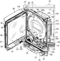
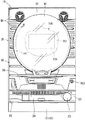
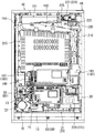
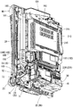
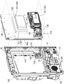
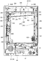
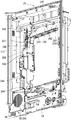
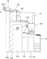
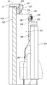
図1は遊技機の外枠の一側に本体枠が開かれその本体枠の一側にガラス扉が開かれた状態を示す斜視図である。図2は遊技機の前側全体を示す正面図である。図3は遊技機の後側全体を示す背面図である。図4は遊技機の本体枠に各種部材が組み付けられた状態を斜め左下方から示す斜視図である。図5は遊技機の本体枠と遊技盤とを分離して示す斜視図である。なお、説明の便宜上、遊技機において遊技者側を前、反対側を後として説明する。   FIG. 1 is a perspective view showing a state in which a main body frame is opened on one side of an outer frame of the gaming machine and a glass door is opened on one side of the main body frame. FIG. 2 is a front view showing the entire front side of the gaming machine. FIG. 3 is a rear view showing the entire rear side of the gaming machine. FIG. 4 is a perspective view showing the state in which various members are assembled to the main body frame of the gaming machine from the lower left side. FIG. 5 is a perspective view showing the main body frame of the gaming machine and the game board separately. For convenience of explanation, in the gaming machine, the player side will be described as the front and the opposite side as the back.

[遊技機の概要について]
図1〜図3に示すように、遊技機としてのパチンコ機は、外枠10、本体枠20、ガラス扉90、遊技盤140等を備えて構成されている。
外枠10は、上下左右の枠材によって縦長四角形の枠状に形成され、同外枠10の前側下部には、本体枠20の下面を受ける下受板15を有している。
外枠10の前面の片側には、本体枠開閉用ヒンジ機構19によって本体枠20が前方に開閉可能に装着されている。
[About the outline of gaming machines]
As shown in FIGS. 1 to 3, a pachinko machine as a gaming machine includes an outer frame 10, a main body frame 20, a glass door 90, a game board 140, and the like.
The outer frame 10 is formed in a vertically rectangular frame shape by upper, lower, left and right frame members, and has a lower receiving plate 15 that receives the lower surface of the main body frame 20 at the lower front side of the outer frame 10.
A main body frame 20 is mounted on one side of the front surface of the outer frame 10 so as to be openable and closable forward by a main body frame opening / closing hinge mechanism 19.

[本体枠について]
図1と図5に示すように、本体枠20は、前枠体21、遊技盤装着枠110及び機構装着体190を合成樹脂材によって一体成形することで構成されている。
本体枠20の前側に形成された前枠体21は、外枠10の前側の下受板15を除く外郭形状に対応する大きさの矩形枠状に形成されている。前枠体21の中央部には遊技盤装着枠110が形成され、その遊技盤装着枠110の後側に機構装着体190が形成されている。
[About the body frame]
As shown in FIGS. 1 and 5, the main body frame 20 is configured by integrally molding a front frame body 21, a game board mounting frame 110 and a mechanism mounting body 190 with a synthetic resin material.
The front frame body 21 formed on the front side of the main body frame 20 is formed in a rectangular frame shape having a size corresponding to the outer shape excluding the support plate 15 on the front side of the outer frame 10. A game board mounting frame 110 is formed at the center of the front frame body 21, and a mechanism mounting body 190 is formed on the rear side of the game board mounting frame 110.

[本体枠のスピーカボックス部について]
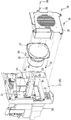
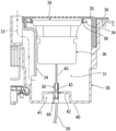
図5と図6に示すように、前枠体21の前側において、遊技盤装着枠110よりも下方に位置する前枠体21の前下部領域の一側(図5では左側)寄りには、スピーカボックス部30が一体に形成され、そのスピーカボックス部30の前側開口部には、同開口部を塞ぐようにしてスピーカ装着部材(スピーカカバー)35がビス等38によって装着されている。このスピーカ装着部材35は、多数のスリット状の貫通孔が貫設された前面板と、その前面板の後側周縁部に沿って後方に向けて突設された周壁部と、を備えて後方に開口する箱形状に形成され、そのスピーカ装着部材35の前面板の内面にはスピーカ(コーン型スピーカ)36がその前面フランジ37においてビス39等によって装着されている。
また、図6と図7に示すように、スピーカボックス部30は、前側が大きく後側に向けてしだいに小さくなった複数段の段差箱形状をなし、図9に示すように、スピーカボックス部30の後壁40とスピーカ36の前面フランジ37との間には音響室31が形成されている。
また、図6と図9に示すように、スピーカボックス部30の内壁面の一側部にはダクト部材34が装着され、これによって前端が前枠体21の前方に開口し後端部が音響室31に連通する音響通路33が形成されている。
[About the speaker box on the main unit frame]
As shown in FIGS. 5 and 6, on the front side of the front frame body 21, closer to one side (the left side in FIG. 5) of the front lower region of the front frame body 21 located below the game board mounting frame 110, A speaker box portion 30 is integrally formed, and a speaker mounting member (speaker cover) 35 is mounted on the front opening portion of the speaker box portion 30 by screws or the like 38 so as to close the opening portion. The speaker mounting member 35 includes a front plate through which a large number of slit-shaped through-holes are provided, and a peripheral wall portion that protrudes rearward along the rear peripheral edge of the front plate. A speaker (cone-type speaker) 36 is attached to the inner surface of the front plate of the speaker mounting member 35 with a screw 39 or the like at the front flange 37 thereof.
Further, as shown in FIGS. 6 and 7, the speaker box unit 30 has a multi-stepped box shape in which the front side is large and gradually becomes small toward the rear side. As shown in FIG. An acoustic chamber 31 is formed between the rear wall 40 of the 30 and the front flange 37 of the speaker 36.
Further, as shown in FIGS. 6 and 9, a duct member 34 is attached to one side of the inner wall surface of the speaker box portion 30 so that the front end opens forward of the front frame body 21 and the rear end portion is acoustic. An acoustic passage 33 communicating with the chamber 31 is formed.

[スピーカボックス部の後壁のコネクタ接続について]
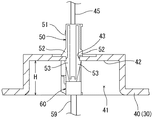
図7図8に示すように、スピーカボックス部30の後壁40の外面(後側)には、凹部41が形成され、その凹部41の底部42にはスピーカ36に対する配線用孔43が貫設されている。そして、図9に示すように、スピーカ36から延出されたスピーカ接続線45の端末コネクタ50が配線用孔43を塞ぐようにして同配線用孔43に弾性的に係合して取り付けられている。
図10〜図12に示すように、スピーカ接続線45の端末コネクタ50は、そのコネクタ本体51の上下の両外側面には、配線用孔43の上下両縁において底部42の内面に当接する当接片52と、底部42の外面に弾性的に係合する弾性係合部53とが形成されている。そして、図10に示すように、端末コネクタ50が底部42の内面側(音響室31側)から配線用孔43に押し込まれることで、底部42の内外両面が当接片52と弾性係合部53との間に狭持され、これによって、配線用孔43を塞ぐようにして端末コネクタ50が止着されるようになっている。
[Connecting the connector on the rear wall of the speaker box]
As shown in FIG. 7, a recess 41 is formed on the outer surface (rear side) of the rear wall 40 of the speaker box portion 30, and a wiring hole 43 for the speaker 36 is provided in the bottom portion 42 of the recess 41. Has been. As shown in FIG. 9, the terminal connector 50 of the speaker connection line 45 extending from the speaker 36 is attached so as to be elastically engaged with the wiring hole 43 so as to block the wiring hole 43. Yes.
As shown in FIGS. 10 to 12, the terminal connector 50 of the speaker connection line 45 is in contact with the inner surfaces of the bottom 42 at both upper and lower edges of the wiring hole 43 on the upper and lower outer surfaces of the connector body 51. A contact piece 52 and an elastic engagement portion 53 that elastically engages with the outer surface of the bottom portion 42 are formed. As shown in FIG. 10, the terminal connector 50 is pushed into the wiring hole 43 from the inner surface side (the acoustic chamber 31 side) of the bottom portion 42, so that both the inner and outer surfaces of the bottom portion 42 are in contact with the contact piece 52 and the elastic engagement portion. Thus, the terminal connector 50 is fastened so as to close the wiring hole 43.

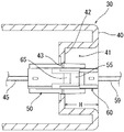
また、図10〜図12に示すように、スピーカ接続線45の端末コネクタ50には、後述する副制御基板166に一端が接続された電源線59の他端の端末コネクタ60が差し込まれて電気的に接続される。この際、配線用孔43に対する弾性係合部53の係合力によって、配線用孔43にスピーカ接続線45の端末コネクタ50が係合保持されるため、同端末コネクタ50が音響室31側に外れることが防止されている。   As shown in FIGS. 10 to 12, the terminal connector 50 of the speaker connection line 45 is inserted into the terminal connector 60 of the other end of the power supply line 59 having one end connected to a sub-control board 166 to be described later. Connected. At this time, since the terminal connector 50 of the speaker connection line 45 is engaged and held in the wiring hole 43 by the engaging force of the elastic engagement portion 53 with respect to the wiring hole 43, the terminal connector 50 is disengaged toward the acoustic chamber 31 side. It is prevented.

前記したように、この実施例において、スピーカ接続線45の端末コネクタ50のコネクタ本体51と、電源線59の端末コネクタ60のコネクタ本体61との相互には、端末コネクタ60の差し込み動作によって弾性的に係合する雄形・雌形の抜け止め用係合部55、65がそれぞれ形成され、これら抜け止め用係合部55、65の係合力によって、スピーカ接続線45の端末コネクタ50から電源線59の端末コネクタ60が不測に外れることが防止されるようになっている。
また、配線用孔43を両端末コネクタ50、60によって塞ぐことができるため、音響室31側の音が漏れて音質低下をまねくという不具合を防止することができる。
As described above, in this embodiment, the connector main body 51 of the terminal connector 50 of the speaker connection line 45 and the connector main body 61 of the terminal connector 60 of the power supply line 59 are elastic to each other by the insertion operation of the terminal connector 60. Male and female retaining engagement portions 55 and 65 that are engaged with each other are formed, and the power of the power supply line from the terminal connector 50 of the speaker connection line 45 is increased by the engagement force of these retaining portions 55 and 65. 59 terminal connectors 60 are prevented from being accidentally disconnected.
In addition, since the wiring hole 43 can be closed by the two terminal connectors 50 and 60, it is possible to prevent a problem that sound on the acoustic chamber 31 side leaks and the sound quality is deteriorated.

また、この実施例において、図10と図11に示すように、スピーカボックス部30の
後壁40に形成された凹部41の深さ寸法Hは、両端末コネクタ50、60が接続された
状態で電源線59側の端末コネクタ60が凹部41の開口から後方に突出されることがな
い程度に設定されている。
これによって、両端末コネクタ50、60に対し異物が当たって外れたり、あるいは損
傷されることが防止される。
Further, in this embodiment, as shown in FIGS. 10 and 11, the depth dimension H of the recess 41 formed in the rear wall 40 of the speaker box 30 is such that both terminal connectors 50 and 60 are connected. The terminal connector 60 on the power supply line 59 side is set so as not to protrude rearward from the opening of the recess 41.
This prevents foreign matter from hitting both terminal connectors 50 and 60 and coming off or being damaged.

[本体枠の前枠体の前側下部の装備品について]
図1と図5に示すように、前枠体21前面の下部領域内の上側部分には遊技盤140の発射通路に向けて球を導く発射レール22が傾斜状に装着され、その発射レール22の側方において本体枠20の前側から操作可能な電源スイッチS1が配置されている。
前枠体21前面の下部領域内の下側部分には、下部前面板23が装着されている。下部前面板23の前面の略中央部には、下皿24が設けられ、片側寄りには操作ハンドル25が設けられている(図1参照)。
[Equipment at the front lower part of the front frame body frame]
As shown in FIGS. 1 and 5, a launch rail 22 that guides a ball toward the launch path of the game board 140 is attached to the upper portion in the lower region of the front surface of the front frame body 21 in an inclined manner. A power switch S1 that can be operated from the front side of the body frame 20 is disposed on the side of the main body frame 20.
A lower front plate 23 is attached to a lower portion in the lower region on the front surface of the front frame body 21. A lower plate 24 is provided at a substantially central portion of the front surface of the lower front plate 23, and an operation handle 25 is provided near one side (see FIG. 1).

[本体枠の前枠体の後側下部の装備品について]
図3と図4に示すように、前枠体21の後側において、遊技盤装着枠110よりも下方に位置する前枠体21の後下部領域の片側(図4に向かって左側)には、発射レール22の下傾端部の発射位置に送られた球を発射するための発射ハンマー73、その発射ハンマー73を作動する発射モータ72等が取付基板71に組み付けられてユニット化された発射装置ユニット70が装着されている。
[Equipment on the rear lower part of the front frame body frame]
As shown in FIGS. 3 and 4, on the rear side of the front frame body 21, one side of the rear lower region of the front frame body 21 located below the game board mounting frame 110 (on the left side in FIG. 4). A launch hammer 73 for firing a ball sent to the launch position of the lower inclined end portion of the launch rail 22, a launch motor 72 for operating the launch hammer 73, etc. are assembled to the mounting substrate 71 and unitized. A device unit 70 is mounted.

また、図4に示すように、前枠体21の後下部領域の略中央部には、電源基板81を有する電源基板ボックス80が装着され、その電源基板ボックス80後側に重ね合わされた状態で払出制御基板86を有する払出制御基板ボックス85が前後に装着されている。
また、図3と図4に示すように、前枠体21の後下部領域の他側寄り部分(ヒンジ寄り部分)において、そのスピーカボックス部30の後段差部の凹み部分に装着された下皿用球誘導ケースの後側に位置してインタフェース基板231を収納しているインタフェース基板ボックス230が装着されている。
In addition, as shown in FIG. 4, a power supply board box 80 having a power supply board 81 is mounted at a substantially central portion of the rear lower region of the front frame body 21 and is superposed on the rear side of the power supply board box 80. A payout control board box 85 having a payout control board 86 is attached to the front and rear.
Further, as shown in FIGS. 3 and 4, the lower plate attached to the recessed portion of the rear step portion of the speaker box portion 30 at the other side portion (the hinge portion) of the rear lower region of the front frame body 21. An interface board box 230 that houses the interface board 231 is mounted on the rear side of the ball guiding case.

[施錠装置について]
図1と図2に示すように、前枠体21のヒンジ機構と反対側に自由端側の後側には、外枠10に対し本体枠20を施錠する機能と、本体枠20に対しガラス扉90を施錠する機能とを兼ね備えた施錠装置100が装着されている。
すなわち、施錠装置100は、外枠10に設けられた閉止具17に係脱可能に係合して本体枠20を閉じ状態に施錠する上下複数の本体枠施錠フック101と、ガラス扉90の自由端側の後側に設けられた閉止具94に係脱可能に係合してガラス扉90を閉じ状態に施錠する上下複数の扉施錠フック102が前方に向けて突出されている。これら扉施錠フック102は、前枠体21の自由端寄り部分に貫設された貫通孔に挿通されてガラス扉90後側の閉止具94に係脱可能に臨んでいる。
[About locking device]
As shown in FIG. 1 and FIG. 2, the function of locking the main body frame 20 with respect to the outer frame 10 on the rear side of the free end side opposite to the hinge mechanism of the front frame body 21, and the glass with respect to the main body frame 20 A locking device 100 having a function of locking the door 90 is mounted.
That is, the locking device 100 includes a plurality of upper and lower main body frame locking hooks 101 that are detachably engaged with a closing tool 17 provided on the outer frame 10 to lock the main body frame 20 in a closed state, and the glass door 90 is free. A plurality of upper and lower door locking hooks 102 that are detachably engaged with a closing tool 94 provided on the rear side of the end side and lock the glass door 90 in a closed state are projected forward. These door locking hooks 102 are inserted into through holes formed in the portion near the free end of the front frame body 21 so as to be detachable from the closing tool 94 on the rear side of the glass door 90.

また、施錠装置100はシリンダー錠103を備え、そのシリンダー錠103の前端部は、遊技機の前方から鍵を挿入されて解錠操作可能に、前枠体21及び下部前面板23を貫通してその下部前面板23の前面に露出されている(図2参照)。
そして、シリンダー錠103の鍵穴に鍵が挿入されて一方向に回動操作されることで本体枠施錠フック101と外枠10の閉止具17との係合が外れて本体枠20が解錠され、これとは逆方向に回動操作されることで、扉施錠フック102とガラス扉90の閉止具94との係合が外れてガラス扉90が解錠されるようになっている。
The locking device 100 includes a cylinder lock 103, and the front end of the cylinder lock 103 passes through the front frame body 21 and the lower front plate 23 so as to be unlocked by inserting a key from the front of the gaming machine. It is exposed on the front surface of the lower front plate 23 (see FIG. 2).
Then, the key is inserted into the keyhole of the cylinder lock 103 and rotated in one direction, so that the engagement between the main body frame locking hook 101 and the closing tool 17 of the outer frame 10 is released and the main body frame 20 is unlocked. By rotating in the opposite direction, the door locking hook 102 and the closure 94 of the glass door 90 are disengaged and the glass door 90 is unlocked.

[ガラス扉について]
図1と図2に示すように、前枠体21の前面の片側には、その前枠体21の上端から下部前面板44の上縁にわたる部分を覆うようにしてガラス扉90が扉開閉用ヒンジ機構89によって前方に開閉可能に装着されている。ガラス扉90のヒンジ機構89と反対側に自由端側の後側には、施錠装置100の扉施錠フック102に係脱可能に係合してガラス扉90を閉じ状態に施錠する閉止具94が設けられている。
また、ガラス扉90の略中央部には、後述する遊技盤140の遊技領域144を前方から透視可能な略円形の開口窓91が形成されている。また、ガラス扉90の後側には開口窓91よりも大きな矩形枠状をなす窓枠92が設けられ、その窓枠92にはガラス板、透明樹脂板等の透明板93が装着されている。
また、ガラス扉90の前面の略全体は、ランプ等が内設された前面装飾部材95によって装飾され、同ガラス扉90の前面の下部には上皿96が形成されている(図2参照)。
[About glass doors]
As shown in FIGS. 1 and 2, a glass door 90 is provided on one side of the front surface of the front frame body 21 so as to cover a portion extending from the upper end of the front frame body 21 to the upper edge of the lower front plate 44. A hinge mechanism 89 is mounted to be openable and closable forward. On the rear side of the free end side opposite to the hinge mechanism 89 of the glass door 90, there is a closing device 94 that detachably engages with the door locking hook 102 of the locking device 100 to lock the glass door 90 in a closed state. Is provided.
In addition, a substantially circular opening window 91 through which a gaming area 144 of a gaming board 140 (to be described later) can be seen through from the front is formed at a substantially central portion of the glass door 90. In addition, a window frame 92 having a rectangular frame shape larger than the opening window 91 is provided on the rear side of the glass door 90, and a transparent plate 93 such as a glass plate or a transparent resin plate is attached to the window frame 92. .
Further, substantially the entire front surface of the glass door 90 is decorated by a front decoration member 95 in which a lamp or the like is provided, and an upper plate 96 is formed at the lower part of the front surface of the glass door 90 (see FIG. 2). .

[本体枠の遊技盤装着枠及び遊技盤について]
図1と図5に示すように、本体枠20の遊技盤装着枠110は、前枠体21の中央部後側に設けられかつ遊技盤140が前方から着脱交換可能に嵌込まれて装着されるようになっている。
すなわち、この実施例において、遊技盤装着枠110の奥側(後側)の枠部内周には遊技盤140の後側の周縁部を受け止める後面受け部111が形成されている。
また、遊技盤装着枠110の一側内壁面の上下部2箇所には、後面受け部111との間に遊技盤140の一側部が差し込み可能な間隔を隔てて前面押え部112が形成されている。
[About the game board mounting frame and game board of the main body frame]
As shown in FIG. 1 and FIG. 5, the game board mounting frame 110 of the main body frame 20 is provided on the rear side of the center part of the front frame body 21 and the game board 140 is detachably fitted and attached from the front. It has become so.
That is, in this embodiment, a rear receiving portion 111 for receiving the rear peripheral portion of the game board 140 is formed in the inner periphery of the rear (rear) frame portion of the game board mounting frame 110.
In addition, front presser portions 112 are formed at two locations on the upper and lower portions of the inner wall surface on the one side of the game board mounting frame 110 with an interval at which one side portion of the game board 140 can be inserted into the rear receiving portion 111. ing.

図1と図5に示すように、遊技盤140は、遊技盤装着枠110の前方から嵌込まれる大きさの略四角板状に形成されている。遊技盤140の盤面(前面)には、外レールと内レールとを備えた案内レール141が設けられ、その案内レール141の内側に遊技領域144が区画形成されている。
また、遊技盤140の前面には、その案内レール141の外側領域において、合成樹脂製の前構成部材140aが装着されている。
As shown in FIGS. 1 and 5, the game board 140 is formed in a substantially square plate shape having a size to be fitted from the front of the game board mounting frame 110. A guide rail 141 having an outer rail and an inner rail is provided on the board surface (front surface) of the game board 140, and a game area 144 is defined inside the guide rail 141.
In addition, a front component member 140a made of synthetic resin is attached to the front surface of the game board 140 in the outer region of the guide rail 141.

また、遊技盤140には、その遊技領域144内において、遊技に関する役物装置、例えば、センタ役物と呼ばれる役物装置150、入賞装置、風車器、誘導釘、ランプ装飾部材等の各種の装備品が配設されている。
また、役物装置150の役物本体151には、その略中央部に開口窓が形成され、役物本体151の後側には、その開口窓に臨んで図柄表示装置(例えば、液晶表示器、EL表示器,プラズマ表示器,CRT等)155が装着されている。
また、図柄表示装置155の後側には、図柄制御基板156が収納された図柄基板ボックス157が装着されている。(図参照)。
Further, the game board 140 has various equipment such as an accessory device related to the game, for example, an accessory device 150 called a center accessory, a winning device, a windmill, a guide nail, a lamp decoration member, etc. in the game area 144. The product is arranged.
The accessory body 150 of the accessory device 150 is formed with an opening window at a substantially central portion thereof, and on the rear side of the accessory body 151, a symbol display device (for example, a liquid crystal display) faces the opening window. 155, EL display, plasma display, CRT, etc.).
In addition, on the rear side of the symbol display device 155, a symbol substrate box 157 in which a symbol control substrate 156 is accommodated is mounted. (See figure).

また、図1に示すように、遊技盤140前面の前構成部材140aの右側寄りの上下2箇所には、遊技盤装着枠110の係止部に対応する位置においてロック部材159がピンと左右方向の長孔によって回動操作可能に装着されている。
そして、遊技盤140(前構成部材140aを含む)は、その左側部が遊技盤装着枠110の後面受け部111と前面押え部112との間に差し込まれ、ロック部材159の先端のロック部が遊技盤装着枠110の係止部に差し込まれて係合されることで遊技盤装着枠110に着脱可能に装着されるようになっている。
Further, as shown in FIG. 1, the lock member 159 is positioned in the left and right positions of the front component 140 a on the front side of the game board 140 at the positions corresponding to the locking portions of the game board mounting frame 110 in the left and right directions. It is mounted so that it can be rotated by a long hole.
The game board 140 (including the front component member 140a) has its left side inserted between the rear receiving part 111 and the front holding part 112 of the game board mounting frame 110, and the lock part at the tip of the lock member 159 is By being inserted into and engaged with a locking portion of the game board mounting frame 110, the game board mounting frame 110 is detachably mounted.

図5に示すように、遊技盤140の後側下部には、その中央部から下部にわたる部分において、各種入賞装置に流入した球を受けかつその球を所定位置まで導く集合樋としての機能とボックス装着部としての機能を兼ね備えたボックス装着台160が設けられている。このボックス装着台160の後側には、副制御基板166が収納された副制御基板ボックス165が装着され、その副制御基板ボックス165の後側に重ね合わされた状態で、主制御基板162が収納された主制御基板ボックス161が装着されている。
さらに、遊技盤140の後側に対しボックス装着台160、副制御基板ボックス165及び主制御基板ボックス161がそれぞれ装着された状態において、本体枠20の遊技盤装着枠110の前方からその遊技盤装着枠110内に遊技盤140を嵌込んで装着できるように、遊技盤140の外郭より外側にはみ出すことなくボックス装着台160、副制御基板ボックス165及び主制御基板ボックス161が配置されている。
As shown in FIG. 5, in the lower part on the back side of the game board 140, a box and a function as a collective bag that receives balls that have flowed into various winning devices and guides the balls to a predetermined position in a portion extending from the center to the lower part. A box mounting base 160 having a function as a mounting portion is provided. A sub-control board box 165 in which the sub-control board 166 is housed is mounted on the rear side of the box mounting base 160, and the main control board 162 is housed in a state of being superimposed on the rear side of the sub-control board box 165. The main control board box 161 is mounted.
Further, in a state where the box mounting base 160, the sub control board box 165 and the main control board box 161 are respectively mounted on the rear side of the game board 140, the game board is mounted from the front of the game board mounting frame 110 of the main body frame 20. The box mounting base 160, the sub control board box 165, and the main control board box 161 are arranged so as not to protrude outward from the outline of the game board 140 so that the game board 140 can be fitted and installed in the frame 110.

[本体枠と遊技盤のコネクタ接続について]
図5に示すように、本体枠20の前側と、遊技盤140の後側との間には、本体枠20の遊技盤装着枠110の前方からその遊技盤装着枠110内に遊技盤140を嵌込む動作によって、それぞれ差し込まれて接続される本体枠側第1、第2のコネクタ120、130と遊技盤側第1、第2のコネクタ170、180がそれぞれ配設されている。
この実施例において、本体枠20の遊技盤装着枠110の後右側部近傍に、第1、第2のコネクタ120、130が左右に隣接して設置され、遊技盤140の後側下部に、遊技盤装着枠110の前方からその遊技盤装着枠110内に遊技盤140を嵌込む動作によって、本体枠側第1、第2のコネクタ120、130に挿脱可能に差し込まれる遊技盤側第1、第2のコネクタ170、180が左右に隣接して設置されている。
[Connecting the main body frame and game board connector]
As shown in FIG. 5, between the front side of the main body frame 20 and the rear side of the game board 140, the game board 140 is inserted into the game board mounting frame 110 from the front of the game board mounting frame 110 of the main body frame 20. The body frame side first and second connectors 120 and 130 and the game board side first and second connectors 170 and 180, which are respectively inserted and connected by the fitting operation, are disposed.
In this embodiment, the first and second connectors 120, 130 are installed adjacent to the left and right sides of the main body frame 20 near the rear right side of the game board mounting frame 110. By inserting the game board 140 into the game board mounting frame 110 from the front of the board mounting frame 110, the game board side first, which is removably inserted into the main body frame side first and second connectors 120, 130, Second connectors 170 and 180 are installed adjacent to the left and right.

本体枠20の第1コネクタ120と遊技盤140の第1コネクタ170は、本体枠20側の払出制御基板86と、遊技盤140側の主制御基板162とを電気的に接続するものである(図22参照)。
図14〜図16に示すように、本体枠20の第1コネクタ120の縦長箱形状をなすコネクタ本体121内には、各種の信号線に対応する複数の信号線用雄型端子122、電圧が異なる(例えば、34V、12V)電源線用雄型プラス端子123、電源線用雄型グランド端子124及び電源線用雄型プラス端子125、電源線用雄型グランド端子126がそれぞれ配置されている。
これに対し、遊技盤140の第1コネクタ170のコネクタ本体171は、本体枠20の第1コネクタ120のコネクタ本体121の外側に嵌込まれる大きさの縦長箱形状に形成されている。そして、コネクタ本体171内には、各雄型端子に対応する複数の信号線用雌型端子172、電源線用雌型プラス端子173、電源線用雌型グランド端子174、電源線用雌型プラス端子175、電源線用雌型グランド端子176がそれぞれ配置されている。
The first connector 120 of the main body frame 20 and the first connector 170 of the game board 140 electrically connect the payout control board 86 on the main body frame 20 side and the main control board 162 on the game board 140 side ( (See FIG. 22).
As shown in FIG. 14 to FIG. 16, a plurality of male terminals 122 for signal lines corresponding to various signal lines, voltages are provided in the connector main body 121 having a vertically long box shape of the first connector 120 of the main body frame 20. Different (for example, 34V, 12V) power source male positive terminals 123, a power source male ground terminal 124, a power source male positive terminal 125, and a power source male ground terminal 126 are arranged.
On the other hand, the connector main body 171 of the first connector 170 of the game board 140 is formed in a vertically long box shape that fits outside the connector main body 121 of the first connector 120 of the main body frame 20. In the connector body 171, a plurality of signal line female terminals 172, a power line female plus terminal 173, a power line female ground terminal 174, and a power line female plus corresponding to each male terminal are provided. A terminal 175 and a power line female ground terminal 176 are respectively disposed.

本体枠20の第2コネクタ130と遊技盤140の第2コネクタ180は本体枠20側のスピーカ36と遊技盤140側の副制御基板166と電気的に接続するものである(図22参照)。
本体枠20の第2コネクタ130には、縦長箱形状をなすコネクタ本体131内に各種の信号線に対応する複数の信号線用雄型端子(図示しない)、所定電圧(例えば、12V)電源線用雄型プラス端子133、電源線用雄型グランド端子134がそれぞれ配置されている。
これに対し、本体枠20の第2コネクタ130のコネクタ本体131の外側に嵌込まれる遊技盤140の第2コネクタ180のコネクタ本体181内には、各雄型端子に対応する複数の雌型信号線用端子(図示しない)、雌型電源線用プラス端子183、雌型電源線用グランド端子184がそれぞれ配置されている。
The second connector 130 of the main body frame 20 and the second connector 180 of the game board 140 are electrically connected to the speaker 36 on the main body frame 20 side and the sub control board 166 on the game board 140 side (see FIG. 22).
The second connector 130 of the main body frame 20 includes a plurality of male terminals for signal lines (not shown) corresponding to various signal lines, a predetermined voltage (for example, 12V) power supply line in the connector main body 131 having a vertically long box shape. A male positive terminal 133 for power supply and a male ground terminal 134 for power supply line are respectively disposed.
On the other hand, in the connector main body 181 of the second connector 180 of the game board 140 fitted outside the connector main body 131 of the second connector 130 of the main body frame 20, a plurality of female signals corresponding to each male terminal are provided. A line terminal (not shown), a female power line plus terminal 183, and a female power line ground terminal 184 are arranged.

また、この実施例において、本体枠20の遊技盤装着枠110の前方からその遊技盤装着枠110内に遊技盤140が嵌込まれ、これによって、本体枠側第1、第2のコネクタ120、130と遊技盤側第1、第2のコネクタ170、180とがそれぞれ差し込まれ
る際、まず、電源線用雄型グランド端子124、126、134が、電源線用雌型グランド端子174、176、184に接続され、その後、電源線用雄型プラス端子123、125、133が電源線用雌型プラス端子173、175、183に接続されるように、これら電源線用雄型グランド端子124、126、134、電源線用雌型グランド端子174、176、184、電源線用雄型プラス端子123、125、133及び電源線用雌型プラス端子173、175、183の端子長さが設定されている。
Further, in this embodiment, the game board 140 is fitted into the game board mounting frame 110 from the front of the game board mounting frame 110 of the main body frame 20, whereby the main body frame side first and second connectors 120, 130 and the game board side first and second connectors 170 and 180 are respectively inserted, first, the power line male ground terminals 124, 126, and 134 are the power line female ground terminals 174, 176, and 184. , And then, the power line male positive terminals 123, 125, 133 are connected to the power line female positive terminals 173, 175, 183, so that the power line male ground terminals 124, 126, 134, female ground terminals 174, 176, 184 for power lines, male positive terminals 123, 125, 133 for power lines, and female plus terminals 173, 175, 1 for power lines Terminal length of 3 is set.

この実施例において、図15に示すように、電源線用雄型グランド端子124(126、134)が、電源線用雄型プラス端子123(125、133)よりも適宜に長く形成されている。
また、電源線用雄型グランド端子124(126、134)と、電源線用雄型プラス端子123(125、133)との長さは略同じとし、電源線用雌型グランド端子174、176、184を電源線用雌型プラス端子173、175、183よりも適宜に長く形成してもよい。
In this embodiment, as shown in FIG. 15, the power line male ground terminal 124 (126, 134) is appropriately longer than the power line male positive terminal 123 (125, 133).
The lengths of the power line male ground terminals 124 (126, 134) and the power line male positive terminals 123 (125, 133) are substantially the same, and the power line female ground terminals 174, 176, 184 may be formed longer than the power supply female positive terminals 173, 175, and 183 as appropriate.

前記したように、電源線用雄型グランド端子124(126、134)を電源線用雌型グランド端子174、176、184に先に接続するように構成することで、仮に、遊技機の電源がONの状態で遊技盤140を脱着交換したとしても、各種回路基板上に配置された電子部品に対し設計経路とは異なる経路で電源電流が流れることが防止される。このため、回路基板上の電子部品に電源電流が不測に流れて損傷される不具合を防止することができる。
すなわち、電源線用雄型プラス端子123、125、133が電源線用雌型プラス端子173、175、183に先に接続されると、電源電流の一部が設計経路とは異なる経路である回路基板上のグランド配線を経る経路で回路基板上に配置された電子部品に不測に流れて損傷する不具合が発生する場合があるが、この実施例においては、このような不具合を未然に防止することができる。
As described above, the power line male ground terminal 124 (126, 134) is configured to be connected to the power line female ground terminal 174, 176, 184 first, so that the power supply of the gaming machine is temporarily Even if the game board 140 is removed and replaced in the ON state, it is possible to prevent a power supply current from flowing through a path different from the design path for electronic components arranged on various circuit boards. For this reason, the malfunction which a power supply current flows into the electronic component on a circuit board unexpectedly, and can be prevented can be prevented.
That is, when the power line male positive terminals 123, 125, 133 are connected to the power line female positive terminals 173, 175, 183 in advance, a part of the power source current is a path different from the design path. There may be a problem that the electronic components arranged on the circuit board flow unexpectedly in the route passing through the ground wiring on the board, and in this embodiment, such a problem must be prevented in advance. Can do.

[本体枠の機構装着体について]
図3と図4に示すように、本体枠20の機構装着体190の上部後側には、島設備から供給される多数の球が貯留可能な球タンク165、その球タンク165の下方に連通するタンクレール171とが配設されている。
また、本体枠20の機構装着体190の片側(図に向かって右側)寄りの上下方向にはユニット化された球払出装置210が装着されている。
[About the body mounting mechanism]
As shown in FIG. 3 and FIG. 4, on the upper rear side of the mechanism mounting body 190 of the main body frame 20, a sphere tank 165 capable of storing a large number of spheres supplied from the island facility and communicated below the sphere tank 165. A tank rail 171 is disposed.
Further, a unitized ball dispensing device 210 is mounted in the vertical direction near one side (right side in the drawing) of the mechanism mounting body 190 of the main body frame 20.

[外部端子基板と分電基板の配置について]
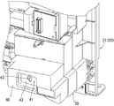
図3と図21に示すように、機構装着体190の後上隅部(ヒンジ寄り側)には、第1基板装着部220と第2基板装着部225とが段差状をなして形成され、下段の第1基板装着部220には外部端子基板222が装着され、上段の第2基板装着部225には分電基板226が分電基板ボックス227に覆われた状態で装着されている。
図20に示すように、遊技盤140後側に配置された図柄制御基板ボックス146及び主制御基板ボックス161の後端部は機構装着体190の中央部に開口された窓開口部に向けて突出している。そして、機構装着体190の窓開口部の一側壁を構成する側壁部と他側壁を構成する払出装置装着部200の片側壁との間には、後カバー体215がその一側を支点として開閉可能に装着されている。
そして、遊技盤140後側の図柄制御基板ボックス146全体及び主制御基板ボックス151の上部が後カバー体215によって覆われるようになっている(図4参照)。
[Disposition of external terminal board and distribution board]
As shown in FIGS. 3 and 21, the first substrate mounting portion 220 and the second substrate mounting portion 225 are formed in a step shape at the rear upper corner (on the hinge side) of the mechanism mounting body 190, An external terminal board 222 is mounted on the lower first board mounting section 220, and a power distribution board 226 is mounted on the upper second board mounting section 225 while being covered with a power distribution board box 227.
As shown in FIG. 20, the rear end portions of the symbol control board box 146 and the main control board box 161 arranged on the rear side of the game board 140 project toward the window opening portion opened in the center portion of the mechanism mounting body 190. ing. The rear cover body 215 is opened and closed with one side as a fulcrum between the side wall portion constituting one side wall of the window opening portion of the mechanism mounting body 190 and the one side wall of the dispensing device mounting portion 200 constituting the other side wall. It is installed as possible.
The entire symbol control board box 146 on the rear side of the game board 140 and the upper part of the main control board box 151 are covered with the rear cover body 215 (see FIG. 4).

[本体枠側の回路基板と遊技盤側の回路基板の接続について]
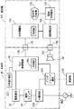
図22のブロック図で示すように、本体枠20側においては、交流電源ACから供給される交流電力が、分電基板226、電源スイッチS1を経て電源基板81に流れ、ここで直流電力に変換されて払出制御基板86に供給される。
また、払出制御基板86は、球を払い出す数を記憶するRAM86aを備え、主制御基板162から送信される払出用信号に従って球を払い出す制御(球払出装置210のモータの作動制御)を行うようになっている。
また、交流電源ACから供給される交流電力は、分電基板226においてインタフェース基板231にも分配供給される。
インタフェース基板231は、球貸機235と払出制御基板86との間に介在され、球貸に関する信号を球貸機235と払出制御基板86との間で送受信可能に電気的に接続するようになっている。
また、払出制御基板86には、各種検出器からの信号や主制御基板162からの信号が伝達される。これに基づいて払出制御基板86から例えば、大当たり信号、扉開放信号、賞球信号等の信号が外部端子基板222に送信され、その外部端子基板222の各外部出力端子から前記した大当たり信号、扉開放信号、賞球信号等の信号がホールコンピュータに伝達されるようになっている。
[Connection between the circuit board on the main body frame side and the circuit board on the game board side]
As shown in the block diagram of FIG. 22, on the main body frame 20 side, AC power supplied from the AC power supply AC flows to the power supply board 81 via the distribution board 226 and the power switch S1, and is converted into DC power here. Then, it is supplied to the payout control board 86.
Further, the payout control board 86 includes a RAM 86a for storing the number of balls to be paid out, and performs control of paying out balls according to a payout signal transmitted from the main control board 162 (operation control of the motor of the ball payout device 210). It is like that.
The AC power supplied from the AC power supply AC is also distributed and supplied to the interface board 231 in the distribution board 226.
The interface board 231 is interposed between the ball lending machine 235 and the payout control board 86, and electrically connects a signal related to ball lending so as to be able to be transmitted and received between the ball lending machine 235 and the payout control board 86. ing.
Further, signals from various detectors and signals from the main control board 162 are transmitted to the payout control board 86. Based on this, a signal such as a jackpot signal, a door opening signal, a prize ball signal or the like is transmitted from the payout control board 86 to the external terminal board 222, and the jackpot signal, door described above is transmitted from each external output terminal of the external terminal board 222. Signals such as an opening signal and a prize ball signal are transmitted to the hall computer.

また、遊技盤140側に配置された主制御基板162は遊技の進行を制御し、副制御基板166は周辺機器を制御する。すなわち主制御基板162からの遊技に関する信号を受けた副制御基板166は、図柄制御基板156を介して図柄表示装置155に表示を行う。
また、図柄制御基板156は、遊技用信号を表示用信号に変換して図柄表示装置155に伝達する。図柄表示装置155には大当たりの抽選図柄が変動表示可能となっている。
Further, the main control board 162 arranged on the game board 140 side controls the progress of the game, and the sub control board 166 controls peripheral devices. In other words, the sub-control board 166 that has received a signal relating to a game from the main control board 162 displays on the symbol display device 155 via the symbol control board 156.
In addition, the symbol control board 156 converts the game signal into a display signal and transmits it to the symbol display device 155. The symbol display device 155 can display a lottery winning symbol in a variable manner.

[本体枠の配線構造について]
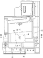
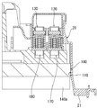
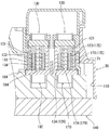
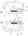
図17〜図20に示すように、遊技盤装着枠110に装着された遊技盤140の後側周辺部のうちの少なくとも左右両側部と機構装着体190の前壁部との間には、第1、第2の配線空間241、251が左右に分離して設けられている。そして、第1配線空間241には電源線240が配線され、第2配線空間251には各種信号に対応する複数本の信号線250が配線されている。
電源線240は、本体枠20の機構装着体190の後側上隅部に配置された分電基板226と、同本体枠20の前枠体21の後側下部に配置された電源基板(この実施例では電源スイッチS1)81とを電気的に接続するものである。
また、信号線250は、本体枠20の機構装着体190の後側上隅部に配置された外部端子基板222と、同本体枠20の前枠体21の後側下部に配置された払出制御基板86とを電気的に接続するものである。
[Wiring structure of main frame]
As shown in FIGS. 17 to 20, there is a gap between at least the left and right side portions of the rear peripheral portion of the game board 140 mounted on the game board mounting frame 110 and the front wall portion of the mechanism mounting body 190. First and second wiring spaces 241 and 251 are provided separately on the left and right. A power line 240 is wired in the first wiring space 241, and a plurality of signal lines 250 corresponding to various signals are wired in the second wiring space 251.
The power supply line 240 includes a power distribution board 226 disposed at the upper rear corner of the mechanism mounting body 190 of the main body frame 20 and a power supply board (this is disposed at the lower rear side of the front frame body 21 of the main body frame 20. In the embodiment, the power switch S1) 81 is electrically connected.
Further, the signal line 250 is connected to the external terminal board 222 disposed at the upper rear corner of the mechanism mounting body 190 of the main body frame 20 and the payout control disposed at the lower rear portion of the front frame body 21 of the main body frame 20. The board 86 is electrically connected.

この実施例おいて、第1配線空間241は、分電基板226と電源基板(この実施例では電源スイッチS1)81との左右方向の距離寸法に対応する横空間部242と、分電基板226と電源基板(この実施例では電源スイッチS1)81との上下方向の距離寸法に対応する縦空間部245とを備えて略逆L字状をなしている。
また、第1配線空間241の横空間部242に対応する機構装着体190の前壁部上部には、略L字状をなして突出しかつ先端部に抜止爪を有する複数の保持片243が左右方向に所定間隔をもって配設されている。
また、第1配線空間241の縦空間部245に対応する機構装着体190の前壁部の右側上部から下部において、略コの字状をなして突出する複数の保持片245が上下方向に所定間隔をもって突設されている。
In this embodiment, the first wiring space 241 includes a horizontal space portion 242 corresponding to the distance between the distribution board 226 and the power supply board 81 (power switch S1 in this embodiment) in the left-right direction, and the distribution board 226. And a vertical space portion 245 corresponding to the vertical distance between the power supply board 81 and the power supply board (power supply switch S1 in this embodiment) and has a substantially inverted L shape.
In addition, a plurality of holding pieces 243 projecting substantially in an L shape and having retaining claws at the front end portion are provided on the left and right sides of the upper portion of the front wall portion of the mechanism mounting body 190 corresponding to the lateral space portion 242 of the first wiring space 241. They are arranged at predetermined intervals in the direction.
In addition, a plurality of holding pieces 245 projecting in a substantially U shape from the right upper part to the lower part of the front wall part of the mechanism mounting body 190 corresponding to the vertical space part 245 of the first wiring space 241 are predetermined in the vertical direction. Projected at intervals.

また、この実施例において、図18に示すように、横空間部242に対応する位置に配置された複数の保持片243は、向きを交互に上下逆向きに形成され、これによって、複数の保持片243に対し電源線240の挿入向きを上方と下方とに交互に換えて掛け渡すことによってその電源線240の挿通作業が容易に行なうことができるとともに、複数の保持片243に掛け渡された電源線240の上下方向への移動が規制され、電源線240の外れが防止されるようになっている。   Further, in this embodiment, as shown in FIG. 18, the plurality of holding pieces 243 arranged at the positions corresponding to the lateral space portion 242 are alternately formed in an upside down direction, whereby a plurality of holding pieces are formed. The insertion direction of the power line 240 is alternately switched between the upper side and the lower side with respect to the piece 243 so that the insertion operation of the power line 240 can be easily performed, and the plurality of holding pieces 243 are spanned. The movement of the power line 240 in the vertical direction is restricted, and the power line 240 is prevented from coming off.

第2配線空間251は、外部端子基板222と払出制御基板86との上下方向の距離寸法に対応して機構装着体190の左側の上部から下部にわたって形成されている。
また、第2配線空間251に対応する機構装着体190の前壁部左前には、略L字状をなして突出しかつ先端部に抜止爪を有する複数の保持片246が適宜姿勢でかつ上下方向に所定間隔をもって配設されている。
The second wiring space 251 is formed from the upper part on the left side of the mechanism mounting body 190 to the lower part corresponding to the vertical distance between the external terminal board 222 and the payout control board 86.
In addition, a plurality of holding pieces 246 projecting in a substantially L shape and having retaining claws at the front end portion in an appropriate posture and in the vertical direction are projected on the front left of the front wall portion of the mechanism mounting body 190 corresponding to the second wiring space 251. Are arranged at predetermined intervals.

[この実施例に係る遊技機の作用効果について]
上述したように構成されるこの実施例に係る遊技機において、遊技盤装着枠110に装着された遊技盤140の後側と機構装着体190の前壁部との間に形成された第1配線空間241には電源線240が配線され、第2配線空間251には信号線250が配線される。これによって、電源線240と信号線250とを左右に分離して配線することができ、ノイズの発生を防止することができる。
しかも、第1、第2の配線空間241、251に電源線240と信号線250とが配線されることで、電源線240及び信号線250が遊技機の後側に露出する部分を、第1、第2の配線空間241、251に相当する分だけ短くすることができ、電源線240や信号線250に異物が引っ掛かる不具合を防止することができる。
[About the effects of the gaming machine according to this embodiment]
In the gaming machine according to this embodiment configured as described above, the first wiring formed between the rear side of the gaming board 140 mounted on the gaming board mounting frame 110 and the front wall portion of the mechanism mounting body 190. A power line 240 is wired in the space 241, and a signal line 250 is wired in the second wiring space 251. As a result, the power supply line 240 and the signal line 250 can be separated from each other on the left and right sides, and noise can be prevented.
In addition, since the power line 240 and the signal line 250 are wired in the first and second wiring spaces 241, 251, the portion where the power line 240 and the signal line 250 are exposed to the rear side of the gaming machine is Therefore, it can be shortened by an amount corresponding to the second wiring spaces 241 and 251, and a problem that foreign matter is caught on the power supply line 240 and the signal line 250 can be prevented.

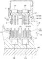
また、この実施例において、電源線240は、その一端(上端)が機構装着体190の後側上隅部の分電基板226に接続される。この電源線240は、機構装着体190の上隅部に設けられた挿通孔を通して機構装着体190の前側に引き出された後、まず、第1配線空間241の横空間部242において、複数の保持片243に順次に挿入されかつその挿入向きを上方と下方とに交互に換えて掛け渡されて係止される。
引き続いて電源線240は、第1配線空間241の縦空間部245において、機構装着体190の前壁部の右側部に設けられた複数の保持片245に順次に挿入されて係止される。そして、電源線240の他端部は、前枠体21の下部右側に配置された電源スイッチS1に接続される。この電源スイッチS1は、図示しない接続線によって電源基板81に接続されている。したがって、電源線240の他端部が電源スイッチS1に接続されることで、分電基板226と電源基板81とが電源線240によって電気的に接続される。
また、前記とは上下逆に、電源スイッチS1側から分電基板226に向けて電源線240を配線することもできる。
In this embodiment, one end (upper end) of the power supply line 240 is connected to the distribution board 226 at the upper rear corner of the mechanism mounting body 190. After the power supply line 240 is drawn out to the front side of the mechanism mounting body 190 through an insertion hole provided in the upper corner of the mechanism mounting body 190, a plurality of holdings are first held in the lateral space portion 242 of the first wiring space 241. The pieces are inserted into the pieces 243 sequentially, and the direction of insertion is alternately changed between upper and lower, and the pieces are spanned and locked.
Subsequently, the power line 240 is sequentially inserted and locked in the plurality of holding pieces 245 provided on the right side portion of the front wall portion of the mechanism mounting body 190 in the vertical space portion 245 of the first wiring space 241. The other end of the power line 240 is connected to a power switch S1 disposed on the lower right side of the front frame 21. The power switch S1 is connected to the power supply substrate 81 by a connection line (not shown). Therefore, the power distribution line 226 and the power supply substrate 81 are electrically connected by the power supply line 240 by connecting the other end of the power supply line 240 to the power switch S1.
In addition, the power supply line 240 can be wired from the power switch S1 side to the power distribution board 226, upside down.

複数の信号線250は、その各一端部(下端部)が前枠体21の後側下部に配置された払出制御基板86に接続される。これら複数の信号線250は、前枠体21の下部左側に貫設された挿通孔を通して機構装着体190の前側に引き出された後、第2配線空間251において、複数の保持片246に順次に挿入されて係止される。
複数の信号線250の上端部は機構装着体190の上左隅部に貫設された挿通孔に挿通されて機構装着体190の後側に引き出された後、機構装着体190の後側上隅部に配置された外部端子基板222に接続され、払出制御基板86と外部端子基板222とが電気的に接続される。
また、前記とは上下逆に、外部端子基板222側から払出制御基板86に向けて複数の信号線250を配線することもできる。
The plurality of signal lines 250 are connected at one end (lower end) thereof to a payout control board 86 disposed at the lower rear side of the front frame body 21. The plurality of signal lines 250 are drawn out to the front side of the mechanism mounting body 190 through an insertion hole penetrating the lower left side of the front frame body 21, and then sequentially to the plurality of holding pieces 246 in the second wiring space 251. Inserted and locked.
The upper ends of the plurality of signal lines 250 are inserted into an insertion hole penetrating the upper left corner of the mechanism mounting body 190 and pulled out to the rear side of the mechanism mounting body 190, and then the rear upper corner of the mechanism mounting body 190. The payout control board 86 and the external terminal board 222 are electrically connected to the external terminal board 222 arranged in the section.
In addition, a plurality of signal lines 250 can be wired from the external terminal board 222 side to the payout control board 86 upside down.

前記したように、機構装着体190の前壁部に一体に形成された複数の保持片243、245、246によって電源線240と信号線250とを第1、第2の配線空間241、251内にそれぞれ配線保持することができる。
これによって、遊技盤装着枠110に対し遊技盤140を着脱する際に、遊技盤140の後側に突出して配置された装備品、例えば、役物装置150の役物本体151、図柄表示装置(図柄基板ボックス157)155、主制御基板ボックス161、副制御基板ボックス165等が電源線240や信号線250に引っ掛かる不具合を防止することができる。
As described above, the power supply line 240 and the signal line 250 are connected in the first and second wiring spaces 241 and 251 by the plurality of holding pieces 243, 245 and 246 formed integrally on the front wall portion of the mechanism mounting body 190. Each wiring can be held.
As a result, when the game board 140 is attached to and detached from the game board mounting frame 110, the equipment that protrudes from the rear side of the game board 140, for example, the accessory body 151 of the accessory device 150, the symbol display device ( It is possible to prevent the design board box 157) 155, the main control board box 161, the sub control board box 165 and the like from being caught by the power line 240 and the signal line 250.

[この発明の他の実施例について]
なお、この発明は前記実施例に限定するものではない。
例えば、前記実施例においては、前枠体21、遊技盤装着枠110及び機構装着体190が合成樹脂材によって一体成形されることで本体枠20が構成される場合を例示したが、前枠体21、遊技盤装着枠110及び機構装着体190がそれぞれ別個に形成され、これら各部材が相互に組み付けられる構造であってもこの発明を実施することができる。
[Other Embodiments of the Invention]
In addition, this invention is not limited to the said Example.
For example, in the embodiment, the case where the main frame 20 is configured by integrally molding the front frame body 21, the game board mounting frame 110, and the mechanism mounting body 190 with a synthetic resin material is illustrated. 21, the game board mounting frame 110 and the mechanism mounting body 190 are formed separately, and the present invention can be implemented even if these members are assembled to each other.

この発明の実施例に係る遊技機の外枠の一側に本体枠が開かれその本体枠の一側にガラス扉が開かれた状態を示す斜視図である。It is a perspective view which shows the state by which the main body frame was opened by the one side of the outer frame of the game machine which concerns on the Example of this invention, and the glass door was opened by the one side of the main body frame. 同じく遊技機の前側全体を示す正面図である。It is a front view which similarly shows the whole front side of a gaming machine. 同じく遊技機の後側全体を示す背面図である。It is a rear view which similarly shows the whole rear side of a gaming machine. 同じく遊技機の本体枠に各種部材が組み付けられた状態を斜め左下方から示す斜視図である。It is a perspective view which shows the state where various members were similarly assembled | attached to the main body frame of the game machine from diagonally lower left. 同じく遊技機の本体枠と遊技盤とを分離して示す斜視図である。It is the perspective view which isolate | separates and shows the main body frame and game board of a gaming machine similarly. 同じく本体枠の下部左側に形成されたスピーカボックスとスピーカとを分離して示す斜視図である。It is a perspective view which isolate | separates and shows the speaker box and speaker similarly formed in the lower left part of the main body frame. 同じく本体枠のスピーカボックスを後側から示す斜視図である。It is a perspective view which similarly shows the speaker box of a main body frame from the rear side. 同じく本体枠のスピーカボックスを後側から示す背面図である。It is a rear view which similarly shows the speaker box of a main body frame from the rear side. 同じく図8のIX−IX線に基づくスピーカボックスの平断面図である。It is a plane sectional view of the speaker box based on the IX-IX line of FIG. 同じくスピーカボックスの後壁の配線孔と端末コネクタを拡大して示す平断面図である。It is the plane sectional view which expands and similarly shows the wiring hole and terminal connector of the rear wall of a speaker box. 同じく図8のXI−XI線に基づくスピーカボックスの平断面図である。It is a plane sectional view of the speaker box based on the XI-XI line of FIG. 同じくスピーカ側接続線の端末コネクタと電源線の端末コネクタとを分離して示す斜視図である。It is a perspective view which isolate | separates and similarly shows the terminal connector of a speaker side connection line, and the terminal connector of a power supply line. 同じく本体枠の遊技盤装着枠に遊技盤が嵌込まれた状態を部分的に示す平断面図である。It is a plane sectional view which shows the state where the game board was similarly inserted in the game board mounting frame of a main part frame similarly. 同じく遊技盤装着枠に遊技盤が嵌込まれたときに本体枠側コネクタと遊技盤側コネクタとが接続された状態を拡大して示す平断面図である。Similarly, when the game board is inserted into the game board mounting frame, the main body frame side connector and the game board side connector are connected in an enlarged plan view. 同じく遊技盤装着枠に遊技盤が嵌込まれる前の本体枠側コネクタと遊技盤側コネクタとの非接続状態を拡大して示す平断面図である。FIG. 6 is an enlarged plan cross-sectional view showing a non-connected state between the main body frame side connector and the game board side connector before the game board is fitted into the game board mounting frame. 同じく本体枠側コネクタと遊技盤側コネクタとを分離して示す斜視図である。It is a perspective view which isolate | separates and shows a main body frame side connector and a game board side connector similarly. 同じく本体枠の機構装着体の前側に設けられた第1、第2配線空間に電源線と信号線とが分離して配線された状態を示す本体枠の正面図である。FIG. 6 is a front view of the main body frame showing a state in which power lines and signal lines are separated and wired in first and second wiring spaces provided on the front side of the mechanism mounting body of the main body frame. 同じく本体枠の機構装着体の前側に設けられた第1配線空間に電源線が配線された状態を斜め左下から示す本体枠の斜視図である。FIG. 6 is a perspective view of the main body frame showing a state in which the power supply line is wired in a first wiring space provided on the front side of the mechanism mounting body of the main body frame, obliquely from the lower left. 同じく本体枠の機構装着体の前側に設けられた第2配線空間に信号線が配線された状態を斜め右下から示す本体枠の斜視図である。Similarly, it is a perspective view of the main body frame showing the state in which the signal lines are wired in the second wiring space provided on the front side of the mechanism mounting body of the main body frame from the lower right. 同じく図17のXX−XX線に基づく本体枠の機構装着体の側断面図である。It is a sectional side view of the mechanism mounting body of the main body frame similarly based on the XX-XX line of FIG. 同じく図17のXXI−XXI線に基づく本体枠の機構装着体の側断面図である。It is a sectional side view of the mechanism mounting body of the main body frame similarly based on the XXI-XXI line of FIG. 同じく本体枠側の各種回路基板と遊技盤側の各種回路基板とが本体枠側コネクタと遊技盤側コネクタによって接続された状態を示すブロック図である。Similarly, it is a block diagram showing a state in which various circuit boards on the main body frame side and various circuit boards on the game board side are connected by a main body frame side connector and a game board side connector.

符号の説明Explanation of symbols

10 外枠
20 本体枠
21 前枠体
81 電源基板
86 払出制御基板
110 遊技盤装着枠
190 機構装着体
222 外部端子基板
226 分電基板
240 電源線
250 信号線
DESCRIPTION OF SYMBOLS 10 Outer frame 20 Main body frame 21 Front frame 81 Power supply board 86 Delivery control board 110 Game board mounting frame 190 Mechanism mounting body 222 External terminal board 226 Distribution board 240 Power supply line 250 Signal line

Claims (1)

前枠体と、その前枠体の略中央部に設けられかつ遊技盤が着脱可能に装着される遊技盤装着枠と、前記遊技盤装着枠の後側に設けられた機構装着体とを備えた遊技機であって、
前記機構装着体に電源線と信号線とがそれぞれ配線されていることを特徴とする遊技機。
A front frame body, a game board mounting frame provided in a substantially central portion of the front frame body and detachably mounted with a game board; and a mechanism mounting body provided on the rear side of the game board mounting frame. A gaming machine,
A gaming machine, wherein a power supply line and a signal line are respectively wired to the mechanism mounting body.
JP2005046926A 2004-03-16 2005-02-23 Game machine Pending JP2005296628A (en)

Priority Applications (1)

Application Number Priority Date Filing Date Title
JP2005046926A JP2005296628A (en) 2004-03-16 2005-02-23 Game machine

Applications Claiming Priority (2)

Application Number Priority Date Filing Date Title
JP2004074359 2004-03-16
JP2005046926A JP2005296628A (en) 2004-03-16 2005-02-23 Game machine

Publications (2)

Publication Number Publication Date
JP2005296628A true JP2005296628A (en) 2005-10-27
JP2005296628A5 JP2005296628A5 (en) 2009-05-14

Family

ID=35328857

Family Applications (1)

Application Number Title Priority Date Filing Date
JP2005046926A Pending JP2005296628A (en) 2004-03-16 2005-02-23 Game machine

Country Status (1)

Country Link
JP (1) JP2005296628A (en)

Cited By (10)

* Cited by examiner, † Cited by third party
Publication number Priority date Publication date Assignee Title
JP2009000190A (en) * 2007-06-20 2009-01-08 Fujishoji Co Ltd Bullet ball machine
JP2009006010A (en) * 2007-06-29 2009-01-15 Sanyo Product Co Ltd Game machine
JP2009006011A (en) * 2007-06-29 2009-01-15 Sanyo Product Co Ltd Game machine
JP2012196555A (en) * 2012-07-25 2012-10-18 Sanyo Product Co Ltd Game machine
JP2012205954A (en) * 2012-08-01 2012-10-25 Sanyo Product Co Ltd Game machine
JP2012232164A (en) * 2012-08-01 2012-11-29 Sanyo Product Co Ltd Game machine
JP2015131205A (en) * 2015-04-22 2015-07-23 株式会社三洋物産 Game machine
JP2015131204A (en) * 2015-04-22 2015-07-23 株式会社三洋物産 Game machine
JP2015131206A (en) * 2015-04-22 2015-07-23 株式会社三洋物産 Game machine
JP2016135387A (en) * 2016-04-28 2016-07-28 株式会社三洋物産 Game machine

Citations (2)

* Cited by examiner, † Cited by third party
Publication number Priority date Publication date Assignee Title
JPH05329265A (en) * 1992-06-01 1993-12-14 Sophia Co Ltd Pinball machine
JP2002028350A (en) * 2000-07-18 2002-01-29 Sophia Co Ltd Game machine

Patent Citations (2)

* Cited by examiner, † Cited by third party
Publication number Priority date Publication date Assignee Title
JPH05329265A (en) * 1992-06-01 1993-12-14 Sophia Co Ltd Pinball machine
JP2002028350A (en) * 2000-07-18 2002-01-29 Sophia Co Ltd Game machine

Cited By (10)

* Cited by examiner, † Cited by third party
Publication number Priority date Publication date Assignee Title
JP2009000190A (en) * 2007-06-20 2009-01-08 Fujishoji Co Ltd Bullet ball machine
JP2009006010A (en) * 2007-06-29 2009-01-15 Sanyo Product Co Ltd Game machine
JP2009006011A (en) * 2007-06-29 2009-01-15 Sanyo Product Co Ltd Game machine
JP2012196555A (en) * 2012-07-25 2012-10-18 Sanyo Product Co Ltd Game machine
JP2012205954A (en) * 2012-08-01 2012-10-25 Sanyo Product Co Ltd Game machine
JP2012232164A (en) * 2012-08-01 2012-11-29 Sanyo Product Co Ltd Game machine
JP2015131205A (en) * 2015-04-22 2015-07-23 株式会社三洋物産 Game machine
JP2015131204A (en) * 2015-04-22 2015-07-23 株式会社三洋物産 Game machine
JP2015131206A (en) * 2015-04-22 2015-07-23 株式会社三洋物産 Game machine
JP2016135387A (en) * 2016-04-28 2016-07-28 株式会社三洋物産 Game machine

Similar Documents

Publication Publication Date Title
JP2005296638A (en) Game machine
JP5561737B2 (en) Game machine
JP2007319231A (en) Pachinko machine
JP2005296628A (en) Game machine
JP5574427B2 (en) Game machine
JP6069026B2 (en) Game machine
JP5078084B2 (en) Game machine
JP3569189B2 (en) Ball game machine
JP2016034446A (en) Game machine
JP4144422B2 (en) Back cover member of gaming machine
JP4341919B2 (en) Game machine
JP5357715B2 (en) Game machine
JP2001161997A (en) Game machine
JP4512805B2 (en) Game machine
JP2015002990A (en) Game machine
JP2000024273A (en) Pachinko machine
JP4000625B2 (en) Game machine
JP5030210B2 (en) Structure for preventing the wiring of the gaming machine from coming off
JP4848044B2 (en) Game machine
JP2000024274A (en) Pachinko machine
JP4628301B2 (en) Game machine
JP5823311B2 (en) Game machine
JP2013162909A (en) Game machine
JP4658019B2 (en) Game machine
JP2006043202A (en) Game machine

Legal Events

Date Code Title Description
A621 Written request for application examination

Free format text: JAPANESE INTERMEDIATE CODE: A621

Effective date: 20060531

A521 Written amendment

Effective date: 20090325

Free format text: JAPANESE INTERMEDIATE CODE: A523

A977 Report on retrieval

Free format text: JAPANESE INTERMEDIATE CODE: A971007

Effective date: 20091105

A131 Notification of reasons for refusal

Free format text: JAPANESE INTERMEDIATE CODE: A131

Effective date: 20091110

RD02 Notification of acceptance of power of attorney

Effective date: 20091204

Free format text: JAPANESE INTERMEDIATE CODE: A7422

A521 Written amendment

Free format text: JAPANESE INTERMEDIATE CODE: A523

Effective date: 20091222

A521 Written amendment

Free format text: JAPANESE INTERMEDIATE CODE: A821

Effective date: 20091204

A02 Decision of refusal

Effective date: 20100316

Free format text: JAPANESE INTERMEDIATE CODE: A02