JP5030210B2 - Structure for preventing the wiring of the gaming machine from coming off - Google Patents
Structure for preventing the wiring of the gaming machine from coming off Download PDFInfo
- Publication number
- JP5030210B2 JP5030210B2 JP2007060292A JP2007060292A JP5030210B2 JP 5030210 B2 JP5030210 B2 JP 5030210B2 JP 2007060292 A JP2007060292 A JP 2007060292A JP 2007060292 A JP2007060292 A JP 2007060292A JP 5030210 B2 JP5030210 B2 JP 5030210B2
- Authority
- JP
- Japan
- Prior art keywords
- control board
- connector
- cover
- side connector
- harness
- Prior art date
- Legal status (The legal status is an assumption and is not a legal conclusion. Google has not performed a legal analysis and makes no representation as to the accuracy of the status listed.)
- Expired - Fee Related
Links
Images


Description
この発明は、遊技機の配線抜け止め防止構造に関し、さらに詳しくは、前扉の裏面側にハーネス(内部配線)を介して接続される制御基板を備えたスロットマシン等の遊技機の配線抜け止め防止構造に関する。 More particularly, the present invention relates to a structure for preventing a wiring machine from being disconnected, and more particularly, to a wiring machine for a gaming machine such as a slot machine provided with a control board connected to the back side of a front door via a harness (internal wiring). Regarding prevention structure.
従来、この種の遊技機の配線抜け止め防止構造にあっては、前扉の裏面側には、中央制御基板が透明な中央制御基板カバーによって覆われた状態で取り付けられていた。この中央制御基板は、スタートレバーやストップボタン等の操作スイッチ類の出力信号をハーネス(内部配線)を介して主制御基板へ送るように構成されている。そのため、中央制御基板に対する不正アクセスがなされて、例えば、不正な電子部品が取り付けられたような場合は、透明なカバーを通してこのような不正を簡単に発見して、迅速な対応処置が行われるようになっていた(例えば、特許文献1参照)。 Conventionally, in this type of gaming machine wiring prevention structure, the central control board is attached to the back side of the front door in a state of being covered by a transparent central control board cover. The central control board is configured to send output signals of operation switches such as a start lever and a stop button to the main control board via a harness (internal wiring). Therefore, when unauthorized access to the central control board is made, for example, when an unauthorized electronic component is attached, such an unauthorized activity can be easily detected through a transparent cover so that a prompt action is taken. (For example, refer to Patent Document 1).
しかしながら、上記した従来の遊技機の配線抜け止め防止構造にあっては、中央制御基板カバーは、中央制御基板に設けられた基板側コネクタと、この基板側コネクタに接続されるハーネス側コネクタとを除いて中央制御基板を覆うように形成されている。このため、基板側コネクタとハーネス側コネクタとは中央制御基板カバーから露出してしまうために、基板側コネクタからハーネス側コネクタが抜出されて、内部的に抽選が当たっている状態にする「打ち込み機」が接続されてしまう虞がある。 However, in the above-described conventional anti-wiring structure for gaming machines, the central control board cover includes a board-side connector provided on the central control board and a harness-side connector connected to the board-side connector. Except for this, it is formed so as to cover the central control board. For this reason, since the board-side connector and the harness-side connector are exposed from the central control board cover, the harness-side connector is pulled out from the board-side connector so that a lottery is made internally. May be connected.
本発明は、こうした事情に鑑みてなされたものであり、前扉の裏面側に取り付けられる制御基板に接続されるハーネス側コネクタを容易に外されないようにした遊技機の配線抜け止め防止構造を提供することを目的とする。 The present invention has been made in view of these circumstances, and provides a wiring retaining prevention structure for a gaming machine in which a harness side connector connected to a control board attached to the back side of the front door is not easily removed. The purpose is to do.
上記目的を達成するため請求項1に記載の発明は、前扉の裏面側に前記裏面と平行に設けられた制御基板と、前記制御基板に設けられた制御基板側コネクタと、前記制御基板側コネクタに前記裏面と平行な方向から挿入されて接続される内部配線のハーネス側コネクタと、係合状態にある前記制御基板側コネクタと前記ハーネス側コネクタを除いて前記制御基板を覆う制御基板カバーと、を備えた遊技機の配線抜け止め防止構造であって、
前記制御基板側コネクタは、係合した前記ハーネス側コネクタの前記内部配線側を係止保持するように開閉動作する一対の可動係止爪を備え、係合状態にある前記制御基板側コネクタと前記ハーネス側コネクタとのほぼ全面を、前記ハーネス側コネクタの前記内部配線側を係止保持した前記一対の可動係止爪を含めてその形状に合わせて弾性力によってほぼ密着した状態で覆うコネクタカバーを設けると共に、前記コネクタカバーには、前記コネクタカバーが前記制御基板カバー内に側方から挿入されて装着された状態、かつ、前記コネクタカバーが係合状態にある前記制御基板側コネクタと前記ハーネス側コネクタとを覆う状態において、前記制御基板を覆った前記制御基板カバーの制御基板表面と直交する方向に設けられた挿入孔と整合する係止孔が前記制御基板表面と直交する方向に設けられているとともに、前記制御基板表面と直交する方向に張り出された凹凸部が一体的に形成され、前記制御基板カバーには、前記コネクタカバーの凹凸部の形状に応じて前記制御基板表面と直交する方向に張り出された張出部が一体的に設けられ、前記コネクタカバーは、前記挿入孔と前記係止孔とが整合した状態で、前記制御基板カバーから離脱することがないように、固定係止爪を備えた固定具によって前記制御基板カバーに抜け止め固定されることを特徴とする。
In order to achieve the above object, the invention according to
The control board side connector includes a pair of movable locking claws that open and close so as to lock and hold the internal wiring side of the engaged harness side connector, and the control board side connector in the engaged state and the A connector cover that covers substantially the entire surface of the harness-side connector, including the pair of movable locking claws that lock and hold the internal wiring side of the harness-side connector, in a state of being in close contact with an elastic force in accordance with its shape. The connector cover is provided with the connector cover inserted into the control board cover from the side and mounted, and the connector cover is in the engaged state and the harness side in the state of covering the connector, consistent with the insertion hole provided in the direction perpendicular to the control board and covered the control group Ithaca bar control surface of the substrate That together with the locking hole is provided in a direction perpendicular to the control board surface, uneven portion which is flared in a direction orthogonal to the control substrate surface are formed integrally, to the control board cover, wherein According to the shape of the concavo-convex portion of the connector cover, an overhanging portion that projects in a direction perpendicular to the control substrate surface is integrally provided, and the insertion hole and the locking hole of the connector cover are aligned. In this state, the control board cover is secured to the control board cover by a fixing tool having a fixing latching claw so as not to be detached from the control board cover.
請求項1に記載の発明によれば、係合状態にある基板側コネクタとハーネス側コネクタとのほぼ全面は、コネクタカバーによってハーネス側コネクタの内部配線側を係止保持した一対の可動係止爪を含めてその形状に合わせてほぼ密着した状態で覆われる。これにより、前扉の裏面側の制御基板に接続されるハーネス側コネクタを容易に外されないようにすることができるようになる。
さらには、このコネクタカバーは、固定係止爪を備えた固定具によって、制御基板カバーにしっかりと抜け止め固定されるようになっている。これにより、制御基板カバー、コネクタカバー、固定具の何れかを壊さない限りは、基板側コネクタからハーネス側コネクタを抜出することはできなくなるので、前扉の裏面側の制御基板に接続されるハーネス側コネクタをより外しにくくすることが可能となる。
また、仮にハーネス側コネクタが制御基板側コネクタから抜出された場合は、制御基板カバー、コネクタカバー、固定具の何れかに壊されたり、白くくもるような痕跡が残るので、不正行為を簡単に発見することができ、迅速に対処処置を行うことができる。
According to the first aspect of the present invention, the substantially entire surface of the board-side connector and the harness-side connector in the engaged state is a pair of movable locking claws in which the internal wiring side of the harness-side connector is locked and held by the connector cover. It is covered in a state of close contact according to its shape . Thereby, the harness side connector connected to the control board on the back side of the front door can be prevented from being easily removed.
Further, the connector cover is securely fixed to the control board cover by a fixing tool having a fixing locking claw. As a result, the harness-side connector cannot be pulled out from the board-side connector unless any of the control board cover, connector cover, or fixture is broken, so that it is connected to the control board on the back side of the front door. It becomes possible to make it harder to remove the harness-side connector.
Also, if when the harness connector is withdrawn from the control board side connector, a control board cover, connector cover, or destroyed in any of the fixture, so remaining traces as cloudy white, easily abuse It is possible to find out and deal with it quickly.
本発明の遊技機の配線抜け止め防止構造によれば、制御基板カバーから露出した基板側コネクタとハーネス側コネクタとの全面をハーネス側コネクタの内部配線側を係止保持した一対の可動係止爪を含めてその形状に合わせてほぼ覆うコネクタカバーを設けると共に、このコネクタカバーを固定具によって中央制御基板カバーに抜け止め固定した。これにより、前扉の裏面側に取り付けられる制御基板に接続されるハーネス側コネクタを容易に外されないようにすることが可能となる。 According to the wiring retaining prevention structure of the gaming machine of the present invention, a pair of movable locking claws that holds and holds the entire surface of the board-side connector and the harness-side connector exposed from the control board cover on the inner wiring side of the harness-side connector. In addition, a connector cover that substantially covers the shape of the connector cover is provided, and the connector cover is secured to the central control board cover by a fixture. Thereby, it is possible to prevent the harness side connector connected to the control board attached to the back side of the front door from being easily removed.
以下、本発明の好適な一実施形態を、スロットマシンを例に図面を参照して説明する。図1は、スロットマシンの正面図、図2は、前扉を開放した状態におけるスロットマシンの内部構造を示した正面図である。 Hereinafter, a preferred embodiment of the present invention will be described with reference to the drawings, taking a slot machine as an example. FIG. 1 is a front view of the slot machine, and FIG. 2 is a front view showing the internal structure of the slot machine with the front door opened.
スロットマシン1は、図1,2に示されるように、前面が開放した矩形状箱体の筐体2(図2に図示)と、この筐体2にスライドヒンジ3,3を介して開閉可能に取り付けられた前扉4と、を備えて構成されている。
As shown in FIGS. 1 and 2, the
まず、筐体2の内部構造について説明する。
筐体2は、図2に示されるように、いずれも木製の上板部2a、左右側板部2b,2c、底板部2d、背板部2eを備えて構成されている。
筐体2内の背板部2eの上部には、スロットマシン1の全体動作を集中制御するCPU(マイコン)を備えた主制御基板20が、硬質プラスチック製のカバー21内に収容された状態で取り付けられている。カバー21は、主制御基板側に設けられた基板側カバーに蓋側カバーが重ね合わされた状態で、両カバー上部間に跨った2つのかしめ具としてのかしめキャップ22により内部封止がなされている。かしめキャップ22は、ほぼ円筒状の本体部の左右側部に一体形成された前後2つの固定係止爪が、それぞれ基板側カバー或いは蓋側カバーの所定位置に係止することにより、基板側カバーと蓋側カバーとを抜け止め固定し、カバー21を封止するようになっている。
First, the internal structure of the housing 2 will be described.
As shown in FIG. 2, the housing 2 includes a wooden
A
また、筐体2内の右側板部2cの上部には、スロットマシン1からホールコンピュータに向かって所定の情報データ(例えば、大当たり、払い戻し数等)を出力するための外部出力端子を備えた外部集中端子基板23が取り付けられている。
In addition, an external output terminal for outputting predetermined information data (for example, jackpot, payout number, etc.) from the
筐体2内の中央には、リール101a,101b,101cを備えた可変表示装置を構成するリールユニット100が配設されている。このリールユニット100は、左右側板部2b,2c、背板部2eによって支持された金属製のフレーム板部2fの上面に載置されているものであって、前扉4が筐体2側に閉じられると、前扉4のパネル面50の表示窓51に、複数種類の図柄や数字等による識別情報が描かれたリール101a,101b,101cが位置するようになっている。
A
リール101a,101b,101cは、それぞれに内蔵されたステッピングモータによって回転駆動されるものであって、リールユニット100の上面には、ステッピングモータへ4相の駆動パルス信号を送出する回胴装置基板24が取り付けられている。そして、主制御基板20が回胴装置基板24に回胴駆動(励磁)パルスデータを送出することで、リールl01a,101b,101cの回転、制動及び停止の制御が行われるようになっている。
The
リールユニット100の下方側、つまり筐体2内の底板部2dの上面中央には、筐体2内に投入されたメダル等の遊技媒体(以下、メダルという)を収容するホッパ装置25が取り付けられている。このホッパ装置25の右側には、このホッパ装置25から溢れたメダルを収容するための補助貯留部26が取り付け固定されている。また、ホッパ装置25の左側には、外部から電力供給を受けて内部装置に必要な電力を供給する主電源装置27が取り付け固定されている。この主電源装置27には、いわゆる配電盤に相当する電源装置基板が内蔵されている。
At the lower side of the
次に、前扉4の外部構成について説明する。
前扉4の前面側は、図1に示されるように、遊技者に面する「前面パネル部」として視覚効果を高めるようにデザインされた所謂化粧板として硬質プラスチックにより一体形成されているものであって、上部パネル部5、下部パネル部6、操作卓7にほぼ区分されるようになっている。
Next, the external configuration of the front door 4 will be described.
As shown in FIG. 1, the front side of the front door 4 is integrally formed of hard plastic as a so-called decorative board designed to enhance the visual effect as a “front panel portion” facing the player. Therefore, the
上部パネル部5の中央には、パネル面50が設けられている。このパネル面50のほぼ中央には、略矩形状の透明な表示窓51が設けられており、この表示窓51を通して、筐体2内に設けられたリールユニット100の3個のリール101a,101b,101cを目視できるようになっている。
A
上部パネル部5の上部や左右側部には、レンズパネルの内部に蛍光灯や高輝度発光ダイオード等の光源を内蔵する照明手段としての照明演出装置52、演出用照明部53a〜53hが配設されている。これら照明演出装置52、演出用照明部53a〜53hは、ゲームの進行に応じて点灯或いは点滅することで、ゲームにおける視覚的な演出効果を高めるようになっている。また、照明手段としての照明演出装置52は、スロットマシン1の遊技状態を報知する手段としても機能するようになっている
On the upper part and the left and right side parts of the
照明演出装置52の下方には、ゲームに係る効果音を発生するスピーカ42a,42b(図2に図示)を内蔵した左右一対の演出用放音部54a,54bと、液晶表示演出装置55とが配設されている。液晶表示演出装置55は、透明な硬質プラスチック板等が嵌め込まれることによって形成されたスロットマシン1の演出装置であって、ゲームの演出に係る映像やゲーム(遊技)に関する情報を主に表示するようになっている。
Below the
下部パネル部6には、スロットマシン1のモデルタイプを遊技者へ認識させる等のため、登場キャラクターの意匠等を表示するパネル61が設けられている。このパネル61の下方には、受皿ユニット62、入賞時にメダルを排出するメダル払出口63、演出効果音を発生するスピーカ49a,49b(図2に図示)を内蔵した演出用放音部64a,64b等が配設されている。さらに、受皿ユニット62には、メダル払出口63から払い出されたメダルを貯留する受皿部62aが一体形成されていると共に、遊技者の喫煙の用に供するための灰皿部材65が設けられている。
The lower panel portion 6 is provided with a
また、パネル61の左右両側には、レンズパネルの内部に高輝度発光ダイオード等の光源を内蔵する演出用照明部66a,66bが配設されている。これら演出用照明部66a,66bは、照明演出装置52、演出用照明部53a〜53hと同様に、ゲームの進行に応じて点灯或いは点滅することで、ゲームにおける視覚的な演出効果を高めるようになっている。
In addition, on both the left and right sides of the
操作卓7は、その上面側(操作パネル)に、メダル投入部71、ベットボタン72,73が配設されていると共に、前面側(フロントマスク)に、スタートレバー74、ストップボタン75a,75b,75c、積算ボタン76、イジェクトボタン77、鍵穴78が配設されている。
The console 7 is provided with a
メダル投入部71には、ゲームに賭けるメダルを筐体2内に投入するためのメダル投入口が一体的に形成されている。
ベットボタン72,73は、スロットマシン1の1ゲームに賭けるメダルの枚数を提示するためのボタンスイッチである。すなわち、ゲームを開始する際に、ベットボタン72を1回押圧操作すると、貯留されているメダルのなかから1枚のメダルがゲームに対して賭けられ、また、ベットボタン73を1回押圧操作すると、3枚のメダルが当該ゲームに賭けられる。このため、ベットボタン72は、「1ベットボタン」、ベットボタン73は、最大枚数のメダルを賭けることができるので、「マックスベットボタン」と呼ばれている。
The
The
スタートレバー74は、リール101a〜101cの回転開始を指示するためのレバースイッチである。
ストップボタン75a,75b,75cは、スタートレバー74によって回転動しているリール101a,101b,101cの回転停止をそれぞれ指示するためのボタンスイッチであって、各リールの配列に対応して並設されている。
精算ボタン76は、ゲームに賭けたメダルの払い出しを指示すると共に、メダルクレジット手段(図示せず)が内部保留したメダルの払い出しを指示するためのボタンスイッチである。
The
The
The
イジェクトボタン77は、メダル投入後に詰まったメダルを排出するボタンスイッチである。
鍵穴78は、前扉4を開錠するための鍵が挿入されるものであって、この鍵穴78にスロットマシン1の管理者などが所定の鍵を挿入して開錠操作すると、スライドヒンジ3,3を介して筐体2に取り付けられた前扉4を前方へ開くことができるようになっている。また、前扉4を筐体2側に閉じると、自動的にこれらを施錠するようになっている。
The
The
次に、前扉4の裏面構造について説明する。
図2に示されるように、前扉4の裏面側上部、つまり、液晶表示装置55の裏面側にあたる位置には、電気回路基板によって形成されたサブ制御基板40が、カバー21と同様の態様により、硬質プラスチック製のカバー41に収納された状態で配設されている。このサブ制御基板40は、液晶表示演出装置55による演出映像の表示制御、照明演出装置52及び演出用照明部53a〜53h、66a,66bを用いた演出効果照明制御、演出用放音部54a,54b,64a,64bを用いた演出効果音制御等、ゲームの演出に係る制御を主に行う。また、このサブ制御基板40の左右側、つまり演出用放音部54a,54bの裏面側にあたる位置には、左右一対のスピーカ42a,42bが配設されている。
Next, the back surface structure of the front door 4 will be described.
As shown in FIG. 2, the
サブ制御基板40の下方側、すなわち、パネル面50の裏面側にあたる位置には、リールl01a,101b,101cの外周面を照射して図柄を明るく表示させるための冷陰極蛍光ランプを収納した収納部43と、冷陰極蛍光ランプを駆動するインバータ44と、硬質プラスチック製の中央制御基板カバー45に収納された中央制御基板46とが、ユニット化された状態で取り付けられている。
A storage unit that stores a cold cathode fluorescent lamp for irradiating the outer peripheral surfaces of the
中央制御基板46の下方には、メダル選別装置47が配設されている。このメダル選別装置47は、メダル投入部71から投入されたメダルの適否を判別し振り分ける装置である。さらに、このメダル選別装置47は、メダルセンサを内蔵しており、ゲームの待機状態等において正規のメダルが投入されてメダルセンサがこのメダルを検出すると、メダル投入の受け付けを示す信号を中央制御基板46へ送出するようになっている。
A
また、メダル選別装置47には、メダル選別装置46の右側面から排出された正規のメダルを筐体2内に設けられたホッパ装置23へ案内する紙面奥側から手前側に延びた平面視J字状のガイド部材48aと、メダル選別装置46により排除されたメダル(或いは異物)を下方のメダル排出口63へ案内するガイド部材48bとが連なっている。さらに、ガイド部材48bの下部には、ホッパ装置23から排出されたメダルをメダル排出口63へ案内するガイド部材48cが連なっている。
また、前扉4の裏面側下部、つまり、演出用放音部62の裏目側にあたる位置には、左右一対のスピーカ49a,49bが配設されている。
Further, the
In addition, a pair of left and right speakers 49 a and 49 b are disposed at the lower part on the back side of the front door 4, that is, the position corresponding to the back side of the effect
そして、スロットマシン1は、遊技者がメダルを投入し、今回の遊技に賭けるメダル数を選択するベットボタン72,73の何れかを押圧操作し、スタートレバー74を叩いてリール101a,101b,101cを回転させ、ストップボタン75a,75b,75cを押してリール101a,101b,101cが停止した際の各リール101a,101b,101cに描かれている図柄や数字等の識別情報が所定の組み合せとなると、その組み合わせの態様に応じて予め定められた枚数のメダルを払い出すようになっている。
Then, in the
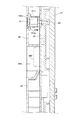
次に、本発明のスロットマシンの配線抜け止め防止構造について図3〜7を用いて説明する。図3は、同例におけるパネル面の裏面側の構造を説明するための分解斜視図、図4は、同例におけるコネクタカバーを説明するための図、図5は、同コネクタカバーが取り付けられたパネル面の裏面側の斜視図、図6は、図5中のA−A矢視断面図、図7は、図5中のB−B矢視断面図である。 Next, a structure for preventing a wiring from coming off in the slot machine of the present invention will be described with reference to FIGS. 3 is an exploded perspective view for explaining the structure of the back surface side of the panel surface in the same example, FIG. 4 is a diagram for explaining the connector cover in the same example, and FIG. 5 is a view in which the connector cover is attached. FIG. 6 is a cross-sectional view taken along the line AA in FIG. 5, and FIG. 7 is a cross-sectional view taken along the line BB in FIG. 5.
図3に示されるように、前扉4(パネル面50)の裏面側には、電気回路基板によって形成された中央制御基板46が、エンジニアリングプラスチック、例えば、PC(ポリカーボネート)製の透明な中央制御基板カバー45によって覆われた状態で取り付けられている。
As shown in FIG. 3, on the back side of the front door 4 (panel surface 50), a
この中央制御基板46の下部には、前扉4の開閉センサ用コネクタ461、投入センサ用コネクタ462、接続モニタ用コネクタ463、ストップボタン用コネクタ464、スタートレバー及びマックスベットボタン用コネクタ465、積算スイッチ及び1ベットボタン用コネクタ466、パネル内照明用コネクタ467、ハーネス(内部配線)接続用の基板側コネクタ468、が一体的に設けられている。基板側コネクタ468には、ハーネス(内部配線)としての50ピンフラットハーネスのハーネス側コネクタ500(図4に図示)の左右下肩部を係止保持するように左右方向に開閉動作する一対の可動係止爪468a,468bを備えている。
Below the
また、中央制御基板46の中央には、ゲームの当たり発生確率を段階的に設定変更する設定変更ボタンが開閉カバー469によって覆われた状態で一体的に設けられている。さらに、この中央制御基板46上には、中央制御基板カバー45をパネル面50の裏面側に固定する固定用ネジ80(図6に図示)が挿通する複数のネジ孔470a,470b,470cが穿設されている。
In the center of the
中央制御基板カバー45は、各コネクタ461〜468及び開閉カバー469を除いて中央制御基板46を覆うように形成されている。このため、係合状態にある基板側コネクタ468とハーネス側コネクタ500とは、この中央制御基板カバー45によって保護されずに、剥き出しのままカバー外に位置することになるので、可動係止爪468a,468bがハーネス側コネクタ500から外されたのち、基板側コネクタ468からハーネス側コネクタ500が抜出されてしまう。
The central
そこで、図3,4に示されるように、係合状態にある基板側コネクタ468とハーネス側コネクタ500とを覆うコネクタカバー600を設けるようにした。さらに、このコネクタカバー600と中央制御基板カバー45とを、固定具としての固定キャップ610によって固定するようにした。
Therefore, as shown in FIGS. 3 and 4, a
詳述すると、コネクタカバー600は、汎用プラスチック、例えば、ABS樹脂により形成されているものであって、中央制御基板カバー45から露出している基板側コネクタ468とハーネス側コネクタ500との面部、つまり、筐体2に臨む面部、下方側に臨む面部、左右側に臨む面部、及びパネル面50に臨む面部(可動係止爪468a,468bのパネル面側のこと)をほぼ覆うように形成された本体部601と、中央制御基板カバー45の内部に挿入配置されてコネクタカバー600と中央制御基板カバー45とを固定キャップ610により固定するための平板状のフランジ部602とを備えている。
なお、図4中の符号501は、フラットハーネスを示している。
More specifically, the
In addition, the code |
本体部601の前面側(筐体2に臨む面側のこと)には、図3に示されるように、前面側に向かって凹凸状に張り出された凹凸部601a,601b,601c,601dが一体的に形成されている。凸部601a,601bは、上方及び奥側(パネル面50に臨む面側)が開放するように形成されている。また、凹部601c,601dは、奥側にフランジ部602が立設されているため、上方及び前面側が開放するように形成されている。
On the front side of the main body 601 (the side facing the housing 2), as shown in FIG. 3, there are concavo-
そして、これら凹凸部601a,601b,601c,601dは、コネクタカバー600を、中央制御基板カバー45、基板側コネクタ468及びハーネス側コネクタ500に装着する際の位置決めをなすと共に、中央制御基板カバー45との接合部の隙間をなくし、かつ、中央制御基板カバー45に固定されたコネクタカバー600の動きを規制、つまり、コネクタカバー600がこじられたとしても、コネクタカバー600が基板側コネクタ468とハーネス側コネクタ500とから離脱することがないように設けられている。
The
そして、図3に示されるように、これら凹凸部601a,601b,601c,601dに応じて、中央制御基板カバー45の下部には、下方に向かって板状に張り出された張出部451a,451b,451c,451dが一体的に設けられている。さらには、張出部451aと451dとは、奥側(パネル面50側)に形成され、張出部451bと451cとは、前面側(筐体2側)に形成されている。
また、張出部451bと451cとの奥側において、フランジ部602が中央制御基板カバー45の下方側からカバー内に挿入されるようになっている。
Then, as shown in FIG. 3, in accordance with these
Further, on the back side of the overhanging
また、図4に示されるように、コネクタカバー600の本体部601の左右側部は、係合状態にある基板側コネクタ468とハーネス側コネクタ500の左右側部に対して弾性力によって圧着するように湾曲形成されている。さらに、その左右側部の上部には、基板側コネクタ468の左右の上肩部に係止可能な内向きの左右一対の係止爪601e,601fが一体形成されている。
Further, as shown in FIG. 4, the left and right side portions of the
一方、コネクタカバー600のフランジ部602の中央には、図3に示されるように、固定キャップ610の筒状の挿入部610aが挿入されると共に、挿入部610aの左右側部に一体形成された左右一対の固定係止爪610b,610c(但し、図3中にあっては、固定係止爪610bのみ図示。固定係止爪610cは、図6の固定キャップ611を参照)が、中央制御基板46に臨んだ面部の周縁部に係止する係止孔602aが穿設されている。
On the other hand, as shown in FIG. 3, a
固定キャップ610は、汎用プラスチック(例えば、ABS樹脂)により形成されているものであって、図3に示されるように、挿入部610aの上部と下部とにほぼ水平な面取りがなされており、挿入部610aを中央制御基板カバー45の所定位置に挿入する際、挿入部610aの左右側に必ず固定係止爪610b,610cが位置するようになっている。また、この挿入部610aの前面側には、矩形状の当接フランジ部610dが一体形成されている。
The fixing
これに応じて、中央制御基板カバー45には、固定キャップ610の挿入部610aが挿入され、かつ当接フランジ部610cをほぼ面一の状態で保持する挿入孔452が凹み形成されている。挿入孔452は、固定キャップ610の挿入部610aの径状に応じて上部と下部とがほぼ水平に面取りがなされており、挿入部610aが挿入される際に、必ず固定係止爪610b,610cを左右側に位置させるようになっている。そして、この挿入孔452の奥側に、コネクタカバー600の係止孔602aが整合するように配置される。
Accordingly, the central
さらに、中央制御基板カバー45には、ネジ孔470a,470b,470cに応じて、固定用ネジ80(図6に図示)を挿通すると共に、固定用ネジ80を封止するための固定キャップ611が挿着される挿入孔453a,453b,453cが凹み形成されていると共に、開閉カバー469を露出させるための挿入孔454が凹み形成されている。
Further, a fixing
固定キャップ611は、固定キャップ610と同様の形態とされている。そのため、挿入孔453a,453b,453cの上部と下部とには、ほぼ水平に面取りがなされていると共に、挿入孔453a,453b,453cの左右側部は、固定キャップ611の固定係止爪611b,611cが係合する横長矩形状の係合孔453a1,453b1,453c1(但し、図3中にあっては片側のみ図示)が設けられている。
The fixed
そして、図5に示されるように、係合状態にある基板側コネクタ468とハーネス側コネクタ500との下方側からコネクタカバー600を挿入すると、コネクタカバー600の本体部601の左右側部は、基板側コネクタ468とハーネス側コネクタ500の左右側部に対して弾性力によって圧着して、可動係止爪468a,468bの開放動作を阻止すると共に、係止爪601e,601fが基板側コネクタ468の左右の上肩部に係止する。そして、その状態において、挿入孔452に固定キャップ610の挿入部610aを挿入して、固定係止爪610b,610cを、コネクタカバー600の係止孔602aの外周縁に係止させることによって、コネクタカバー600は、下方への抜け止めが行われた状態で中央制御基板カバー45に一体的に固定される。
Then, as shown in FIG. 5, when the
なお、ハーネス側コネクタ500から送出されるハーネス501は、図7に示されるように、コネクタカバー600とパネル面50との間の空間Sを通って主制御基板20に接続されるようになっている。
The
以上説明したように本発明によれば、係合状態にある基板側コネクタ468とハーネス側コネクタ500とのほぼ全面は、コネクタカバー600によってほぼ密着した状態で覆われる。これにより、前扉4の裏面側の中央制御基板45に接続されるハーネス側コネクタ500を容易に外されないようにすることができるようになる。
さらには、このコネクタカバー600は、固定係止爪610b,610cを備えた固定キャップ610によって、制御基板カバーにしっかりと抜け止め固定されるようになっている。これにより、中央制御基板カバー45、コネクタカバー600、固定キャップ610の何れかを壊さない限りは、基板側コネクタ468からハーネス側コネクタ500を抜出することはできなくなるので、前扉4の裏面側の中央制御基板46に接続されるハーネス側コネクタ500をより外しにくくすることが可能となる。
また、仮にハーネス側コネクタ500が中央制御基板側コネクタ468から抜出された場合は、中央制御基板カバー45、コネクタカバー600、固定キャップ610の何れかに壊されたり、白くくもるような痕跡が残るので、不正行為を簡単に発見することができ、迅速に対処処置を行うことができる。
As described above, according to the present invention, almost the entire surface of the board-
Further, the
Further, if the
1…スロットマシン(遊技機)
4…前扉
45…中央制御基板カバー
452…挿入孔
46…中央制御基板
468…基板側コネクタ
500…ハーネス側コネクタ
501…ハーネス(内部配線)
600…コネクタカバー
601…本体部
601e,601f…係止爪
602…フランジ部
602a…係止孔
610…固定キャップ(固定具)
610a…挿入部
610b,610c…固定係止爪
1 ... Slot machine (game machine)
4 ...
600 ...
610a:
Claims (1)
前記制御基板側コネクタは、係合した前記ハーネス側コネクタの前記内部配線側を係止保持するように開閉動作する一対の可動係止爪を備え、
係合状態にある前記制御基板側コネクタと前記ハーネス側コネクタとのほぼ全面を、前記ハーネス側コネクタの前記内部配線側を係止保持した前記一対の可動係止爪を含めてその形状に合わせて弾性力によってほぼ密着した状態で覆うコネクタカバーを設けると共に、
前記コネクタカバーには、前記コネクタカバーが前記制御基板カバー内に側方から挿入されて装着された状態、かつ、前記コネクタカバーが係合状態にある前記制御基板側コネクタと前記ハーネス側コネクタとを覆う状態において、前記制御基板を覆った前記制御基板カバーの制御基板表面と直交する方向に設けられた挿入孔と整合する係止孔が前記制御基板表面と直交する方向に設けられているとともに、前記制御基板表面と直交する方向に張り出された凹凸部が一体的に形成され、
前記制御基板カバーには、前記コネクタカバーの凹凸部の形状に応じて前記制御基板表面と直交する方向に張り出された張出部が一体的に設けられ、
前記コネクタカバーは、前記挿入孔と前記係止孔とが整合した状態で、前記制御基板カバーから離脱することがないように、固定係止爪を備えた固定具によって前記制御基板カバーに抜け止め固定されることを特徴とする遊技機の配線抜け止め防止構造。 A control board provided in parallel to the back side on the back side of the front door, a control board side connector provided on the control board, and the control board side connector inserted and connected from a direction parallel to the back side An anti-wiring prevention structure for a gaming machine comprising: a harness side connector for internal wiring; and a control board cover that covers the control board except for the control board side connector and the harness side connector in an engaged state. ,
The control board side connector includes a pair of movable locking claws that open and close to lock and hold the internal wiring side of the engaged harness side connector,
Fit almost the entire surface of the control board side connector and the harness side connector in the engaged state to the shape including the pair of movable locking claws that lock and hold the internal wiring side of the harness side connector. While providing a connector cover that covers almost in close contact with the elastic force,
The connector cover includes the control board side connector and the harness side connector in a state in which the connector cover is inserted and attached from the side into the control board cover, and the connector cover is in an engaged state. in the state of covering, locking holes in alignment with the insertion hole provided in the direction perpendicular to the control board and covered the control group Ithaca bar control substrate surface is provided in a direction perpendicular to the control board surface And the uneven part projected in the direction orthogonal to the control substrate surface is formed integrally ,
The control board cover is integrally provided with an overhang part that projects in a direction orthogonal to the control board surface according to the shape of the concavo-convex part of the connector cover,
The connector cover is prevented from being detached from the control board cover by a fixture having a fixing latching claw so that the connector hole is not detached from the control board cover in a state where the insertion hole and the locking hole are aligned. A structure for preventing the wiring of a gaming machine from being fixed.
Priority Applications (1)
| Application Number | Priority Date | Filing Date | Title |
|---|---|---|---|
| JP2007060292A JP5030210B2 (en) | 2007-03-09 | 2007-03-09 | Structure for preventing the wiring of the gaming machine from coming off |
Applications Claiming Priority (1)
| Application Number | Priority Date | Filing Date | Title |
|---|---|---|---|
| JP2007060292A JP5030210B2 (en) | 2007-03-09 | 2007-03-09 | Structure for preventing the wiring of the gaming machine from coming off |
Related Child Applications (1)
| Application Number | Title | Priority Date | Filing Date |
|---|---|---|---|
| JP2011154195A Division JP2011229953A (en) | 2011-07-12 | 2011-07-12 | Structure for preventing disconnection of wiring of game machine |
Publications (2)
| Publication Number | Publication Date |
|---|---|
| JP2008220490A JP2008220490A (en) | 2008-09-25 |
| JP5030210B2 true JP5030210B2 (en) | 2012-09-19 |
Family
ID=39839796
Family Applications (1)
| Application Number | Title | Priority Date | Filing Date |
|---|---|---|---|
| JP2007060292A Expired - Fee Related JP5030210B2 (en) | 2007-03-09 | 2007-03-09 | Structure for preventing the wiring of the gaming machine from coming off |
Country Status (1)
| Country | Link |
|---|---|
| JP (1) | JP5030210B2 (en) |
Families Citing this family (1)
| Publication number | Priority date | Publication date | Assignee | Title |
|---|---|---|---|---|
| JP5938293B2 (en) * | 2012-08-08 | 2016-06-22 | 株式会社平和 | Game machine |
Family Cites Families (5)
| Publication number | Priority date | Publication date | Assignee | Title |
|---|---|---|---|---|
| JPS5352988A (en) * | 1976-10-25 | 1978-05-13 | Hitachi Ltd | Preventing device of connector drop |
| JPH03106922U (en) * | 1990-02-20 | 1991-11-05 | ||
| JP2005021444A (en) * | 2003-07-03 | 2005-01-27 | Samii Kk | Lower panel structure of slot machine |
| JP4150378B2 (en) * | 2005-02-09 | 2008-09-17 | サミー株式会社 | Connector pull-out restriction device |
| JP4188331B2 (en) * | 2005-03-25 | 2008-11-26 | サミー株式会社 | Board case |
-
2007
- 2007-03-09 JP JP2007060292A patent/JP5030210B2/en not_active Expired - Fee Related
Also Published As
| Publication number | Publication date |
|---|---|
| JP2008220490A (en) | 2008-09-25 |
Similar Documents
| Publication | Publication Date | Title |
|---|---|---|
| JP2008229168A (en) | Game machine | |
| JP2010201107A (en) | Game machine | |
| JP5252526B2 (en) | Structure for preventing unauthorized operation of gaming machines | |
| JP4812410B2 (en) | Board case device for gaming machine | |
| JP2008245816A (en) | Game machine | |
| JP5598944B2 (en) | Board case mounting structure for gaming machines | |
| JP5030210B2 (en) | Structure for preventing the wiring of the gaming machine from coming off | |
| JP2007167168A (en) | Game table | |
| JP5126781B2 (en) | Control board assembly for gaming machines | |
| JP2009039281A (en) | Fraudulent action preventing structure of game machine | |
| JP2005052448A (en) | Board case | |
| JP2006122367A (en) | Control board unit in game machine | |
| JP5057559B2 (en) | Board case | |
| JP2011229953A (en) | Structure for preventing disconnection of wiring of game machine | |
| JP4447543B2 (en) | Game stand board storage case | |
| JP4985947B2 (en) | Structure for preventing unauthorized operation of setting change buttons on gaming machines | |
| JP2008073326A (en) | Game machine | |
| JP3822965B2 (en) | Slot machine | |
| JP4694830B2 (en) | Control board unit for gaming machines | |
| JP5263850B2 (en) | Structure for preventing unauthorized operation of gaming machines | |
| JP2005168950A (en) | Game machine | |
| JP4643177B2 (en) | Game machine | |
| JP4850399B2 (en) | Control board unit for gaming machines | |
| JP5077988B2 (en) | Game machine | |
| JP5030198B2 (en) | Game machine |
Legal Events
| Date | Code | Title | Description |
|---|---|---|---|
| A621 | Written request for application examination |
Free format text: JAPANESE INTERMEDIATE CODE: A621 Effective date: 20091104 |
|
| RD02 | Notification of acceptance of power of attorney |
Free format text: JAPANESE INTERMEDIATE CODE: A7422 Effective date: 20091104 |
|
| RD04 | Notification of resignation of power of attorney |
Free format text: JAPANESE INTERMEDIATE CODE: A7424 Effective date: 20100714 |
|
| A131 | Notification of reasons for refusal |
Free format text: JAPANESE INTERMEDIATE CODE: A131 Effective date: 20110513 |
|
| A977 | Report on retrieval |
Free format text: JAPANESE INTERMEDIATE CODE: A971007 Effective date: 20110512 |
|
| A521 | Written amendment |
Free format text: JAPANESE INTERMEDIATE CODE: A523 Effective date: 20110712 |
|
| A131 | Notification of reasons for refusal |
Free format text: JAPANESE INTERMEDIATE CODE: A131 Effective date: 20110823 |
|
| A521 | Written amendment |
Free format text: JAPANESE INTERMEDIATE CODE: A523 Effective date: 20111019 |
|
| TRDD | Decision of grant or rejection written | ||
| A01 | Written decision to grant a patent or to grant a registration (utility model) |
Free format text: JAPANESE INTERMEDIATE CODE: A01 Effective date: 20120608 |
|
| A01 | Written decision to grant a patent or to grant a registration (utility model) |
Free format text: JAPANESE INTERMEDIATE CODE: A01 |
|
| A61 | First payment of annual fees (during grant procedure) |
Free format text: JAPANESE INTERMEDIATE CODE: A61 Effective date: 20120622 |
|
| R150 | Certificate of patent or registration of utility model |
Ref document number: 5030210 Country of ref document: JP Free format text: JAPANESE INTERMEDIATE CODE: R150 Free format text: JAPANESE INTERMEDIATE CODE: R150 |
|
| FPAY | Renewal fee payment (event date is renewal date of database) |
Free format text: PAYMENT UNTIL: 20150706 Year of fee payment: 3 |
|
| R250 | Receipt of annual fees |
Free format text: JAPANESE INTERMEDIATE CODE: R250 |
|
| R250 | Receipt of annual fees |
Free format text: JAPANESE INTERMEDIATE CODE: R250 |
|
| R250 | Receipt of annual fees |
Free format text: JAPANESE INTERMEDIATE CODE: R250 |
|
| R250 | Receipt of annual fees |
Free format text: JAPANESE INTERMEDIATE CODE: R250 |
|
| S531 | Written request for registration of change of domicile |
Free format text: JAPANESE INTERMEDIATE CODE: R313531 |
|
| R350 | Written notification of registration of transfer |
Free format text: JAPANESE INTERMEDIATE CODE: R350 |
|
| LAPS | Cancellation because of no payment of annual fees |