JP2005296466A - Improved resin-coated ornamental button and manufacturing method of the same - Google Patents
Improved resin-coated ornamental button and manufacturing method of the same Download PDFInfo
- Publication number
- JP2005296466A JP2005296466A JP2004119481A JP2004119481A JP2005296466A JP 2005296466 A JP2005296466 A JP 2005296466A JP 2004119481 A JP2004119481 A JP 2004119481A JP 2004119481 A JP2004119481 A JP 2004119481A JP 2005296466 A JP2005296466 A JP 2005296466A
- Authority
- JP
- Japan
- Prior art keywords
- resin
- groove
- button
- design sheet
- button body
- Prior art date
- Legal status (The legal status is an assumption and is not a legal conclusion. Google has not performed a legal analysis and makes no representation as to the accuracy of the status listed.)
- Pending
Links
- 229920005989 resin Polymers 0.000 title claims abstract description 24
- 239000011347 resin Substances 0.000 title claims abstract description 24
- 238000004519 manufacturing process Methods 0.000 title claims abstract description 6
- 239000002184 metal Substances 0.000 claims abstract description 23
- 229910052751 metal Inorganic materials 0.000 claims abstract description 23
- 230000002093 peripheral effect Effects 0.000 claims abstract description 20
- 229920003002 synthetic resin Polymers 0.000 claims abstract description 17
- 239000000057 synthetic resin Substances 0.000 claims abstract description 17
- 238000005520 cutting process Methods 0.000 claims description 8
- 238000000034 method Methods 0.000 abstract description 5
- 239000011248 coating agent Substances 0.000 abstract description 2
- 238000000576 coating method Methods 0.000 abstract description 2
- 238000012856 packing Methods 0.000 abstract 1
- 239000003822 epoxy resin Substances 0.000 description 6
- 229920000647 polyepoxide Polymers 0.000 description 6
- 239000000463 material Substances 0.000 description 5
- HCHKCACWOHOZIP-UHFFFAOYSA-N Zinc Chemical group [Zn] HCHKCACWOHOZIP-UHFFFAOYSA-N 0.000 description 2
- 238000005422 blasting Methods 0.000 description 2
- 238000005034 decoration Methods 0.000 description 2
- 238000005406 washing Methods 0.000 description 2
- 229910052725 zinc Inorganic materials 0.000 description 2
- 239000011701 zinc Substances 0.000 description 2
- 229910001229 Pot metal Inorganic materials 0.000 description 1
- 238000004512 die casting Methods 0.000 description 1
- 238000005108 dry cleaning Methods 0.000 description 1
- 230000000694 effects Effects 0.000 description 1
- 239000007769 metal material Substances 0.000 description 1
- 230000000630 rising effect Effects 0.000 description 1
- 238000009958 sewing Methods 0.000 description 1
Images
Landscapes
- Adornments (AREA)
Abstract
Description
本発明は、文字や図柄等のデザイン面に透明エポキシ樹脂をコーティングした装飾釦を改良したものと、その製造方法に関する。 The present invention relates to an improved decorative button in which a transparent epoxy resin is coated on the design surface of characters, designs, etc., and a method for manufacturing the same.
従来の樹脂被覆装飾釦は、金属製などの平滑な釦本体表面に対して予め文字や図形が印刷されたデザインシートを貼着した後、デザインシートの表面に透明エポキシ樹脂を流し込んで固化させたものが主流となっている。夕暮時や夜間における通学児童の視認性向上を図るべくデザインシートに再帰性光反射材を用いるなど、デザインシートはバリエーションに富んだものが提供されていた。 A conventional resin-coated decorative button is made by sticking a design sheet preprinted with characters and figures on the surface of a smooth button body made of metal or the like, and then pouring a transparent epoxy resin on the surface of the design sheet to solidify it. Things have become mainstream. A variety of design sheets were provided, such as using a retroreflective material for the design sheets to improve the visibility of school children in the evening and at night.
例えば前記再帰性光反射材を用いた装飾釦として、亜鉛ダイキャスト製の釦本体に貼着する再帰性光反射材の外周端面に予めシール処理を施しておき、透明エポキシ樹脂が反射材に流入することを防止して光反射特性を維持したもの(特許文献1)、あるいは釦本体に貼着した再帰性光反射材上に透明板を配設し、両部材の全周部分のみを接着しつつ透明板上に対して透明エポキシ樹脂を流し込むことにより光反射特性を維持したもの(特許文献2)等が例示される。本発明者も、より簡易な構造でありながら文字等が浮き上がって見えるデザイン性の高い装飾釦を先に提案した(特許文献3)。 For example, as a decorative button using the retroreflective material, the outer peripheral end face of the retroreflective material to be attached to the zinc die-cast button body is preliminarily sealed, and the transparent epoxy resin flows into the reflective material. A transparent plate is disposed on a retroreflective material that is protected from light (Patent Document 1) or on a button body, and only the entire circumference of both members is adhered. An example is one that maintains light reflection characteristics by pouring a transparent epoxy resin onto the transparent plate (Patent Document 2). The present inventor also previously proposed a decorative button with high design that allows characters and the like to appear while having a simpler structure (Patent Document 3).
こうした装飾釦は、一般に、文字や図形等が描かれたデザインシートの表面に樹脂被覆されているので、デザインシートの汚れや変色が防止されて釦表面がいつまでも美しく、ドライクリーニングや家庭における洗濯への耐久性においても優れているという特徴があるものの、学生服のように長期間に亘って使用され、繰り返し洗濯されると、金属製である釦本体と樹脂製である被覆部分との膨張・収縮率の相違に起因して、希にではあるが樹脂被覆部分が釦本体から剥離してしまうことがあった。 Such decorative buttons are generally coated with resin on the surface of a design sheet on which characters, figures, etc. are drawn. Therefore, the design sheet is prevented from being stained and discolored, and the button surface is always beautiful, making it suitable for dry cleaning and washing at home. Although it is characterized by excellent durability, when used for a long period of time like student clothes and repeatedly washed, the metal button body and the resin cover part will expand. Due to the difference in shrinkage rate, the resin-coated portion sometimes peeled off from the button body.
この点、前記特許文献2においては、樹脂被覆部分の剥離予防を図るべく、釦本体の開口凹部における内周面に突条を設けたり、ホーニングやブラスト加工によって微細の凹凸を形成し、被覆した透明合成樹脂の外れ防止を図ることが提案されている。しかしながら、コスト軽減の観点からダイキャスト成形されるのが通例である釦本体の内周面に突条を形成するのは実質的には不可能であったし、微細の凹凸を設けるホーニング加工やブラスト加工では剥離防止効果が十分に得られない場合があった。
In this respect, in
しかるに本発明では、従来の樹脂被覆装飾釦に改良を施して、短時間かつ省工程で樹脂被覆の脱落を確実に防止することができる装飾釦とその製造方法の提供を課題とするものである。 However, an object of the present invention is to provide a decorative button that can improve the conventional resin-coated decorative button and reliably prevent the resin coating from falling off in a short time and in a reduced process. .
前記所期の課題解決を図るため、本発明に係る改良された樹脂被覆装飾釦では、デザインシートの表面側に透明合成樹脂を充填固化することにより得られる従来の樹脂被覆装飾釦において、前記デザインシートが敷設される金属製釦本体の開口部内周面に溝を刻設することとした。 In order to solve the intended problem, the improved resin-coated decorative button according to the present invention is the conventional resin-coated decorative button obtained by filling and solidifying a transparent synthetic resin on the surface side of the design sheet. A groove was engraved on the inner peripheral surface of the opening of the metal button body on which the sheet is laid.
樹脂被覆装飾釦における金属製釦本体は、通例はダイキャスト成形された亜鉛製であり、金属製や樹脂フィルム製(再帰性光反射フィルムの表面側に重ねる場合も含む)デザインシートの表面側にエポキシ樹脂等の透明合成樹脂を充填固化するために、表面側に開口部が設けられている。本発明では、この開口部の側壁とも言える内周面に溝を刻設することにしたのである。ここで、刻設される溝は、内周面を一周し連続する溝であってもよいし、分断された不連続の溝であってもよい。また、内周面の開口部端縁からデザインシート敷設面に至る幅広の溝であってもよいし、透明合成樹脂が充填される部分において細幅に刻設した溝であってもよい。さらに、溝の断面形状は凹形やU字形、テーパー形など様々な形状を採用しうる。 The metal button body of the resin-coated decorative button is usually made of die-cast zinc, and is made of metal or resin film (including the case where it is superimposed on the surface side of the retroreflective film) on the surface side of the design sheet. In order to fill and solidify a transparent synthetic resin such as an epoxy resin, an opening is provided on the surface side. In the present invention, a groove is engraved on the inner peripheral surface which can be said to be the side wall of the opening. Here, the groove to be engraved may be a continuous groove that goes around the inner peripheral surface, or may be a discontinuous groove that is divided. Further, it may be a wide groove extending from the opening edge of the inner peripheral surface to the design sheet laying surface, or may be a groove formed in a narrow width in a portion filled with the transparent synthetic resin. Further, the cross-sectional shape of the groove may be various shapes such as a concave shape, a U shape, and a tapered shape.
そして、本発明に係る前記改良された樹脂被覆装飾釦の製造方法は、デザインシート敷設面に直交する軸を回転軸として金属製釦本体を回転させながら、該釦本体の開口部内周面であって開口部端縁よりデザインシート敷設面寄りの位置に切削刃先を当接させることにより溝を刻設するものである。例えば、金属製釦本体の開口部を外に向けた状態で、モータに接続されたチャックにより金属製釦本体を保持させ、金属製釦本体を回転させながらその開口部内周面に切削刃を当接させることにより溝を刻設することにした。 Then, the improved resin-coated decorative button manufacturing method according to the present invention is the inner peripheral surface of the opening of the button body while rotating the metal button body about the axis orthogonal to the design sheet laying surface. Then, the groove is carved by bringing the cutting edge into contact with the position closer to the design sheet laying surface than the edge of the opening. For example, with the opening of the metal button body facing outward, the metal button body is held by a chuck connected to a motor, and the cutting blade is applied to the inner peripheral surface of the opening while rotating the metal button body. It was decided to make a groove by making contact.
本発明に係る改良された樹脂被覆装飾釦では、開口部内に充填固化させた透明合成樹脂の周縁が、金属製釦本体の開口部内周面に刻設した溝内に流入し、両者が完全に嵌合した状態となるので、洗濯等に際して膨張・収縮した際にも透明合成樹脂の剥離・脱落を防止することができ、いつまでも美しい装飾釦とすることができる。 In the improved resin-coated decorative button according to the present invention, the periphery of the transparent synthetic resin filled and solidified in the opening flows into the groove formed on the inner peripheral surface of the opening of the metal button body, and both are completely Since it is in a fitted state, it is possible to prevent the transparent synthetic resin from peeling and dropping even when it is expanded or contracted during washing or the like, and it is possible to make a beautiful decorative button forever.
また、本発明に係る前記改良された樹脂被覆装飾釦の製造方法によれば、金属製釦本体を回転装置にセットし、デザインシート敷設面に直交する軸を回転軸として金属製釦本体を回転させながら切削刃先を当接するだけでよいので、複雑な工程を要することなく短時間に必要な溝を刻設することができる。 In addition, according to the improved method of manufacturing a resin-coated decorative button according to the present invention, the metal button body is set on the rotating device, and the metal button body is rotated about the axis orthogonal to the design sheet laying surface. Therefore, it is only necessary to abut the cutting edge while making it possible to cut a necessary groove in a short time without requiring a complicated process.
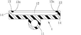
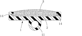
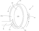
以下、本発明に係る改良された樹脂被覆装飾釦等について、図面に従って詳細に説明する。図1は本発明による装飾釦本体の一例を示す縦断面図であり、図2は同装飾釦本体にデザインシートを敷設して透明合成樹脂を充填固化させた完成品の縦断面図である。また、図3は装飾釦本体に溝を刻設している状態を示す斜視図である。 Hereinafter, an improved resin-coated decorative button and the like according to the present invention will be described in detail with reference to the drawings. FIG. 1 is a longitudinal sectional view showing an example of a decorative button body according to the present invention. FIG. 2 is a longitudinal sectional view of a finished product in which a design sheet is laid on the decorative button body and filled with a transparent synthetic resin and solidified. FIG. 3 is a perspective view showing a state in which a groove is formed in the decorative button body.
樹脂被覆装飾釦につき、従来から一般的に用いられている亜鉛等の金属材料をダイキャスト成形してなる金属製釦本体1には、裏面側中央に被服等と縫着するための脚部11が延設されている一方、表面側には開口部12が設けられている。開口部12は略垂直に立ち上がった枠縁13により囲まれているので、本発明では、その枠縁13の内周面13aに溝14を刻設する。この溝14の深さや幅は、金属製釦本体1を破損しない程度で適宜決定しうる。なお、本例の溝14は、枠縁13を一周するように、その内周面13a全面に亘って連続して刻設されているが、既に述べたように、内周面13aの一部分のみに刻設することとしたり、断続的に刻設することとしたり、あるいは2重以上の溝として刻設することにしてもよい。
A
図2に示されるように、溝14が刻設された金属製釦本体1には、その開口部内にデザインシート2が敷設され、このデザインシート2の表面側に透明合成樹脂3が充填されることになる。透明合成樹脂3としては、汎用されているエポキシ樹脂が好適に用いられるが、充填した際に溝14内に流入させた状態で固化させることが肝要である。こうして固化した透明合成樹脂3は、その周縁部分が溝14と嵌合状態にあるので、透明合成樹脂3や金属製釦本体1の膨張・収縮によっても透明合成樹脂3の脱落を防止することができるわけである。
As shown in FIG. 2, a
以上のような溝14は、切削刃を用いて簡単に刻設することができる。すなわち、図3に示される加工例では、金属製釦本体1を、その開口部12内にあるデザインシート敷設面121に直交する軸を回転軸として回転させながら(図3の例では、矢印で示した反時計回り方向)、金属製釦本体1の開口部12における内周面13aに対して切削刃先Bを当接させるのである。金属製釦本体1を回転させるには、モータに接続されたチャック等により金属製釦本体1を保持させればよく、回転方向は切削刃先Bの当接方向に合わせて設定すればよい。
The
このとき、切削刃先Bを当接させる部分としては、開口部12の枠縁13における枠縁13の内周面13aであって、開口部12の端縁、つまり枠縁13の上縁よりもデザインシート敷設面121寄りの位置であることが望ましいが、デザインシート敷設面121からは離隔しておくのが望ましい。開口部12の端縁に近づくと溝14の上縁が欠けてしまって透明合成樹脂3との嵌合が得られないおそれがある一方、デザインシート敷設面121に近接ないし連続してしまうとデザインシート2が溝14内に入ってしまって開口部12中心と整合せず、偏ってしまうおそれがあるからである。
At this time, as a portion with which the cutting edge B is brought into contact, the inner
1 金属製釦本体
2 デザインシート
3 透明合成樹脂
11 脚部
12 開口部
13 枠縁
13a 内周面
14 溝
B 切削刃先
DESCRIPTION OF
Claims (2)
Priority Applications (1)
| Application Number | Priority Date | Filing Date | Title |
|---|---|---|---|
| JP2004119481A JP2005296466A (en) | 2004-04-14 | 2004-04-14 | Improved resin-coated ornamental button and manufacturing method of the same |
Applications Claiming Priority (1)
| Application Number | Priority Date | Filing Date | Title |
|---|---|---|---|
| JP2004119481A JP2005296466A (en) | 2004-04-14 | 2004-04-14 | Improved resin-coated ornamental button and manufacturing method of the same |
Publications (1)
| Publication Number | Publication Date |
|---|---|
| JP2005296466A true JP2005296466A (en) | 2005-10-27 |
Family
ID=35328719
Family Applications (1)
| Application Number | Title | Priority Date | Filing Date |
|---|---|---|---|
| JP2004119481A Pending JP2005296466A (en) | 2004-04-14 | 2004-04-14 | Improved resin-coated ornamental button and manufacturing method of the same |
Country Status (1)
| Country | Link |
|---|---|
| JP (1) | JP2005296466A (en) |
Cited By (3)
| Publication number | Priority date | Publication date | Assignee | Title |
|---|---|---|---|---|
| KR101080582B1 (en) | 2008-09-11 | 2011-11-04 | 김광배 | A Cutton and it's manufacturing process |
| CN102602757A (en) * | 2011-01-24 | 2012-07-25 | 株式会社日立制作所 | Button switch for elevator and elevator equipment |
| CN102715711A (en) * | 2012-03-27 | 2012-10-10 | 嘉善县大舜奔马钮扣服饰厂 | Resin-dropped button and production process thereof |
Citations (4)
| Publication number | Priority date | Publication date | Assignee | Title |
|---|---|---|---|---|
| JPS5638605U (en) * | 1979-09-03 | 1981-04-11 | ||
| JPS57194303U (en) * | 1981-06-04 | 1982-12-09 | ||
| JP2001231610A (en) * | 2000-02-22 | 2001-08-28 | Nagai Botan Kk | Decorative small article and its manufacturing method |
| JP2002532264A (en) * | 1998-12-15 | 2002-10-02 | エルヴィン ユンカー マシーネンファブリーク ゲゼルシャフト ミット ベシュレンクテル ハフツング | Method of turning an inside contour on a workpiece and a tool mount |
-
2004
- 2004-04-14 JP JP2004119481A patent/JP2005296466A/en active Pending
Patent Citations (4)
| Publication number | Priority date | Publication date | Assignee | Title |
|---|---|---|---|---|
| JPS5638605U (en) * | 1979-09-03 | 1981-04-11 | ||
| JPS57194303U (en) * | 1981-06-04 | 1982-12-09 | ||
| JP2002532264A (en) * | 1998-12-15 | 2002-10-02 | エルヴィン ユンカー マシーネンファブリーク ゲゼルシャフト ミット ベシュレンクテル ハフツング | Method of turning an inside contour on a workpiece and a tool mount |
| JP2001231610A (en) * | 2000-02-22 | 2001-08-28 | Nagai Botan Kk | Decorative small article and its manufacturing method |
Cited By (3)
| Publication number | Priority date | Publication date | Assignee | Title |
|---|---|---|---|---|
| KR101080582B1 (en) | 2008-09-11 | 2011-11-04 | 김광배 | A Cutton and it's manufacturing process |
| CN102602757A (en) * | 2011-01-24 | 2012-07-25 | 株式会社日立制作所 | Button switch for elevator and elevator equipment |
| CN102715711A (en) * | 2012-03-27 | 2012-10-10 | 嘉善县大舜奔马钮扣服饰厂 | Resin-dropped button and production process thereof |
Similar Documents
| Publication | Publication Date | Title |
|---|---|---|
| FR2778135B1 (en) | PROCESS FOR PRODUCING A PART IN PLASTIC MATERIAL PARTIALLY COATED WITH A FILM, ESPECIALLY DECORATIVE | |
| JP5364834B1 (en) | Decorative parts for vehicles | |
| JP2005296466A (en) | Improved resin-coated ornamental button and manufacturing method of the same | |
| ITTO980375A1 (en) | PROCEDURE FOR MANUFACTURING DECORATIVE ELEMENTS IN PLASTIC FOR GLASSES | |
| US20080062379A1 (en) | Rim of Spectacle | |
| JPS58221741A (en) | Trim strip for automobile body and manufacture of said trim strip | |
| JPS5840046Y2 (en) | pearl production | |
| JP2007152931A (en) | Seal base material, seal, and decorative implement | |
| KR20060036170A (en) | Emblem and its manufacturing method | |
| BE1000747A7 (en) | Decorative panel engraving system - involves marking design through layer of paint on back of transparent panel and filling grooves with paint of other colours | |
| KR100396176B1 (en) | Pattern molding method in pair glass for window | |
| KR200197102Y1 (en) | For decoration of metal board | |
| KR0129561Y1 (en) | Compact case with transparent lid | |
| KR200261508Y1 (en) | a picture frame | |
| KR200374219Y1 (en) | Emblem | |
| JPS6222132B2 (en) | ||
| KR200284475Y1 (en) | A ring | |
| JPS59127715A (en) | Roll for forming profile with projections | |
| JPH0315352Y2 (en) | ||
| JP2017213747A (en) | Decorative synthetic resin molded article and manufacturing method therefor | |
| KR200289178Y1 (en) | a sticker solid glitter | |
| KR200244649Y1 (en) | Seal | |
| JPS6031711Y2 (en) | goggles | |
| JPS5938408Y2 (en) | gloves | |
| KR200416427Y1 (en) | Celebratory Cup. |
Legal Events
| Date | Code | Title | Description |
|---|---|---|---|
| A621 | Written request for application examination |
Free format text: JAPANESE INTERMEDIATE CODE: A621 Effective date: 20070222 |
|
| A977 | Report on retrieval |
Free format text: JAPANESE INTERMEDIATE CODE: A971007 Effective date: 20090903 |
|
| A131 | Notification of reasons for refusal |
Free format text: JAPANESE INTERMEDIATE CODE: A131 Effective date: 20100105 |
|
| A02 | Decision of refusal |
Free format text: JAPANESE INTERMEDIATE CODE: A02 Effective date: 20100506 |