JP2005296442A - Game device - Google Patents
Game device Download PDFInfo
- Publication number
- JP2005296442A JP2005296442A JP2004119116A JP2004119116A JP2005296442A JP 2005296442 A JP2005296442 A JP 2005296442A JP 2004119116 A JP2004119116 A JP 2004119116A JP 2004119116 A JP2004119116 A JP 2004119116A JP 2005296442 A JP2005296442 A JP 2005296442A
- Authority
- JP
- Japan
- Prior art keywords
- batter
- baseball
- game
- ball
- target area
- Prior art date
- Legal status (The legal status is an assumption and is not a legal conclusion. Google has not performed a legal analysis and makes no representation as to the accuracy of the status listed.)
- Withdrawn
Links
- 238000003384 imaging method Methods 0.000 claims abstract description 12
- 238000000034 method Methods 0.000 description 44
- 238000012545 processing Methods 0.000 description 29
- 238000001514 detection method Methods 0.000 description 20
- 230000003287 optical effect Effects 0.000 description 9
- 230000000007 visual effect Effects 0.000 description 9
- 238000003780 insertion Methods 0.000 description 8
- 230000037431 insertion Effects 0.000 description 8
- 230000000694 effects Effects 0.000 description 7
- 238000010586 diagram Methods 0.000 description 6
- 239000000463 material Substances 0.000 description 2
- NJPPVKZQTLUDBO-UHFFFAOYSA-N novaluron Chemical compound C1=C(Cl)C(OC(F)(F)C(OC(F)(F)F)F)=CC=C1NC(=O)NC(=O)C1=C(F)C=CC=C1F NJPPVKZQTLUDBO-UHFFFAOYSA-N 0.000 description 2
- 238000006243 chemical reaction Methods 0.000 description 1
- 238000012937 correction Methods 0.000 description 1
- 238000007599 discharging Methods 0.000 description 1
- 230000005484 gravity Effects 0.000 description 1
- 238000011084 recovery Methods 0.000 description 1
- 238000012546 transfer Methods 0.000 description 1
- 239000013598 vector Substances 0.000 description 1
Images


Landscapes
- Processing Or Creating Images (AREA)
Abstract
【課題】 プレーヤが球を放つゲームを行うこと可能であり、興趣性に富んだゲームを行うことが可能なゲーム装置を提供すること。
【解決手段】 プレーヤによって放たれる球の標的となる標的領域を表示する標的領域表示手段と、球を打ち返すための打具をスイングさせる駆動手段と、標的に向けて放たれた球を撮像する球撮像手段と、球撮像手段により撮像された球の画像に基づいて、球の軌道及び速度を演算し、球の到達点及び到達時間を算出する算出手段と、算出手段による算出結果に基づいて、打具が到達時間に到達点を通過するように、駆動手段による打具のスイングを制御する制御手段とを備えたことを特徴とするゲーム装置。
【選択図】 図1PROBLEM TO BE SOLVED: To provide a game device capable of playing a game in which a player releases a ball and capable of playing a game with great interest.
SOLUTION: Target area display means for displaying a target area as a target of a sphere released by a player, driving means for swinging a hitting tool for hitting the sphere, and imaging a sphere released toward the target Based on the sphere imaging means, a calculation means for calculating the trajectory and speed of the sphere based on the image of the sphere imaged by the sphere imaging means, and calculating the arrival point and arrival time of the sphere, and based on the calculation result by the calculation means A game apparatus comprising: control means for controlling swing of the hitting tool by the driving means so that the hitting tool passes the arrival point at the arrival time.
[Selection] Figure 1
Description
本発明は、例えば、バッティングセンタ、ゲームセンタ、テーマパーク等の各種アミューズメント施設に設置されるゲーム装置に関する。 The present invention relates to a game apparatus installed in various amusement facilities such as a batting center, a game center, and a theme park.
従来から、打席に向けて野球ボールを自動的に投げるピッチングマシンを装備したバッティングセンタはよく知られている。バッティングセンタにおいては、ピッチングマシンによって所定時間ごとに投げられる野球ボールをプレーヤが打つようになっている。このようなピッチングマシンのなかには、野球ボールの速度やコースを利用者が設定することができるものもある。 Conventionally, a batting center equipped with a pitching machine that automatically throws a baseball at a batting base is well known. In the batting center, a player hits a baseball that is thrown every predetermined time by a pitching machine. Some of these pitching machines allow the user to set the speed and course of the baseball.
従来のゲーム装置としては、例えば、打席に向けて野球ボールを投げる手段と、プレーヤが打った野球ボールの軌道及び速度を算出する手段と、算出結果に基づいて野球ゲームのシミュレーションを行う手段とを備えたゲーム装置が存在する(例えば、特許文献1参照)。特許文献1に記載のゲーム装置によれば、従来のバッティングセンタのように単に野球ボールを打つというだけではなく、打った結果に基づいて野球ゲームのシミュレーションが行われるため、プレーヤに対して実際に野球ゲームを行っているかのような感覚を与えることができる。 As a conventional game device, for example, means for throwing a baseball ball toward the batting base, means for calculating the trajectory and speed of the baseball ball hit by the player, and means for simulating a baseball game based on the calculation result There is a game device provided (see, for example, Patent Document 1). According to the game device described in Patent Document 1, since a baseball game is simulated based on the result of hitting, not only hitting a baseball ball like a conventional batting center, It can give the feeling of playing a baseball game.
しかしながら、これらのゲームは、いずれもピッチングマシンから投げられた野球ボールを打つというゲーム、すなわち、野球の打撃に関するゲームであるが、野球の投球に関するゲームではない。野球の投球に関するゲームとしては、例えば、ストライクゾーンが所定数の標的に区画されており、プレーヤは打席に向けて野球ボールを投げることにより、各標的に野球ボールを当てていくというゲームが存在する。
このゲームは、野球の投球に関するゲーム自体が少ないということもあって、人気を博しているが、対戦相手が存在しないということもあって、ゲームの興趣性に欠けるものである。野球において投球は打撃とともに重要であり、人気のある要素であるため、興趣性に富んだ投球に関するゲームの登場が要望されている。
However, each of these games is a game of hitting a baseball ball thrown from a pitching machine, that is, a game related to baseball hitting, but is not a game related to baseball pitching. As a game related to baseball pitching, for example, there is a game in which a strike zone is divided into a predetermined number of targets, and a player throws a baseball ball at a bat to hit a baseball ball to each target. .
This game is popular due to the fact that there are few games related to baseball pitching, but there is no opponent, so the game is not interesting. In baseball, pitching is important as well as hitting, and is a popular element. Therefore, there is a demand for an entertaining game related to pitching.
本発明は上述した問題に鑑みてなされたものであり、その目的は、プレーヤが球を放つゲームを行うこと可能であり、興趣性に富んだゲームを行うことが可能なゲーム装置を提供することにある。 The present invention has been made in view of the above-described problems, and an object of the present invention is to provide a game device in which a player can play a game in which a ball is released and which can play a game that is highly entertaining. It is in.
上述した課題を解決するために、本発明は、以下のようなものを提供する。
(1)プレーヤによって放たれる球の標的となる標的領域を表示する標的領域表示手段と、
上記球を打ち返すための打具をスイングさせる駆動手段と、
上記標的に向けて放たれた球を撮像する球撮像手段と、
上記球撮像手段により撮像された上記球の画像に基づいて、上記球の軌道及び速度を演算し、上記球の到達点及び到達時間を算出する算出手段と、
上記算出手段による算出結果に基づいて、上記打具が上記到達時間に上記到達点を通過するように、上記駆動手段による上記打具のスイングを制御する制御手段と
を備えたことを特徴とするゲーム装置。
In order to solve the above-described problems, the present invention provides the following.
(1) target area display means for displaying a target area that is a target of a sphere released by the player;
Driving means for swinging a hitting tool for hitting the ball;
Sphere imaging means for imaging a sphere released toward the target;
Calculation means for calculating the trajectory and speed of the sphere based on the image of the sphere imaged by the sphere imaging means, and calculating the arrival point and arrival time of the sphere;
Control means for controlling the swing of the hitting tool by the driving means so that the hitting tool passes the arrival point at the arrival time based on the calculation result by the calculating means. Game device.
(1)の発明によれば、プレーヤが標的に向けて放った球が打具によって打ち返されるため、プレーヤに対して、打者と対戦しているような感覚を抱かせることが可能な興趣性に富んだゲームを提供することができる。 According to the invention of (1), since the ball released by the player toward the target is returned by the hitting tool, the player can have an interest that makes him feel as if he is playing against the batter. A rich game can be provided.
さらに、本発明は、以下のようなものを提供する。
(2) 上記(1)に記載のゲーム装置であって、
プレーヤにより投入された貨幣を識別する貨幣識別手段と、
上記貨幣識別手段により識別された貨幣の額に応じた数の球を払い出す球払出手段と
を備えたことを特徴とする。
Furthermore, the present invention provides the following.
(2) The game device according to (1) above,
Money identifying means for identifying money inserted by the player;
And a ball paying means for paying out a number of balls according to the amount of money identified by the money identifying means.
(2)の発明によれば、貨幣を投入すると、貨幣の額に応じた数の球が自動的にプレーヤに対して払い出されるため、利便性に優れる。 According to the invention of (2), when money is inserted, the number of balls corresponding to the amount of money is automatically paid out to the player, which is excellent in convenience.
さらに、本発明は、以下のようなものを提供する。
(3) 上記(1)又は(2)に記載のゲーム装置であって、
上記標的領域の表示又は非表示を選択する旨の指示を入力する第1指示入力手段を備え、
上記標的領域表示手段は、上記第1指示入力手段により入力された指示に応じて、上記標的領域の表示又は非表示を行うことを特徴とする。
Furthermore, the present invention provides the following.
(3) The game device according to (1) or (2) above,
Comprising first instruction input means for inputting an instruction to select display or non-display of the target area;
The target area display means displays or hides the target area in accordance with an instruction input by the first instruction input means.
(3)の発明によれば、例えば、ゲームに不慣れなプレーヤは標的領域を表示してゲームを行い、ゲームに熟練したプレーヤは標的領域を表示せずにゲームを行うというように、ゲームに対する熟練度等に応じて、プレーヤ自身が標的領域の表示/非表示を選択してゲームを行うことができる。 According to the invention of (3), for example, a player who is unfamiliar with the game plays the game by displaying the target area, and a player who is skilled in the game plays the game without displaying the target area. Depending on the degree or the like, the player himself / herself can select a display / non-display of the target area and play the game.
さらに、本発明は、以下のようなものを提供する。
(4) 上記(1)〜(3)のいずれか1に記載のゲーム装置であって、
複数種類の上記標的領域のなかから、いずれか1の標的領域を選択する旨の指示を入力する第2指示入力手段を備え、
上記標的領域表示手段は、上記第2指示入力手段により入力された指示に応じて、選択された種類の標的領域の表示を行うことを特徴とする。
Furthermore, the present invention provides the following.
(4) The game device according to any one of (1) to (3) above,
A second instruction input means for inputting an instruction to select any one target area from the plurality of types of target areas;
The target area display means displays the target area of the selected type in accordance with the instruction input by the second instruction input means.
(4)の発明によれば、標的領域をプレーヤ自身が選択してゲームを行うことができるため、例えば、外角低めのコースに球を投げる練習をするというように、プレーヤ自身が行いたいゲームを行うことが可能になる。従って、ゲームに多様性を持たせることができ、より興趣性に富んだゲームを行うことが可能になる。 According to the invention of (4), since the player can select the target area and play the game, for example, the player himself / herself wants to play the game he / she wants to play, such as practicing throwing a ball on a course with a lower outer angle. It becomes possible to do. Therefore, it is possible to give the game diversity, and it is possible to play a game that is more interesting.
さらに、本発明は、以下のようなものを提供する。
(5) 上記(1)〜(4)のいずれか1に記載のゲーム装置であって、
互いに異なるフォームが設定された複数の打者のなかから、いずれか1の打者を対戦相手として選択する旨の指示を入力する第3指示入力手段を備え、
上記制御手段は、上記第3指示入力手段により入力された指示に応じて、選択された打者のフォームで打具をスイングするように、上記駆動手段による上記打具のスイングを制御することを特徴とする。
Furthermore, the present invention provides the following.
(5) The game device according to any one of (1) to (4) above,
A third instruction input means for inputting an instruction to select any one batter as an opponent from a plurality of batters having different forms;
The control means controls the swing of the hitting tool by the driving means so as to swing the hitting tool in the form of the selected batter according to the instruction input by the third instruction input means. And
(5)の発明によれば、例えば、実在する野球選手のなかから、1人の野球選手を対戦相手として選択すると、その野球選手のフォームで打具がスイングされるようになるため、あたかも実在する野球選手と対戦しているような感覚をプレーヤに与えることができ、ゲームの興趣性を向上させることができる。 According to the invention of (5), for example, when one baseball player is selected as an opponent from among existing baseball players, the hitting tool swings in the form of the baseball player, so that It is possible to give the player a feeling that he is playing against a baseball player, and to improve the fun of the game.
さらに、本発明は、以下のようなものを提供する。
(6) 上記(1)〜(5)のいずれか1に記載のゲーム装置であって、
互いに異なるフォームが設定された複数の打者のなかから、いずれか1の打者を対戦相手として選択する旨の指示を入力する第3指示入力手段と、
選択された打者を示す打者画像を表示する打者画像表示手段と、
上記駆動手段による打具のスイングにあわせて、選択された打者が当該打者に設定されたフォームでスイングするように、当該打者画像の表示制御を行う打者画像表示制御手段と
を備えたことを特徴とする。
Furthermore, the present invention provides the following.
(6) The game device according to any one of (1) to (5) above,
A third instruction input means for inputting an instruction to select any one batter as an opponent from a plurality of batters set with different forms;
Batter image display means for displaying a batter image indicating the selected batter;
Batter image display control means for performing display control of the batter image so that the selected batter swings in the form set for the batter according to the swing of the hitting tool by the driving means. And
(6)の発明によれば、例えば、実在する野球選手のなかから、1人の野球選手を対戦相手として選択すると、打具のスイングにあわせて、その野球選手がスイングする様子を示す画像が表示されるため、あたかも実在する野球選手と対戦しているような感覚をプレーヤに与えることができ、ゲームの興趣性を向上させることができる。 According to the invention of (6), for example, when one baseball player is selected as an opponent from among the existing baseball players, an image showing how the baseball player swings in accordance with the swing of the hitting tool. Since it is displayed, it is possible to give the player a feeling as if they are playing against a real baseball player, and to improve the fun of the game.
本発明の構成によれば、プレーヤが球を放つゲームを行うことが可能であり、興趣性に富んだゲームを行うことが可能となる。 According to the configuration of the present invention, it is possible to play a game in which a player releases a ball, and it is possible to play a game that is highly entertaining.
本発明の実施形態について図面に基づいて説明する。
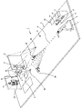
図1は、本発明のゲーム装置の一例を模式的に示す斜視図である。
ゲーム装置1のフィールド2上には、ピッチャープレート3と、ホームベース4とが設置されている。フィールド2上において、プレーヤPは、ピッチャープレート3側から、ホームベース4側へ野球ボールBを投げることにより、ゲームを行うことができる。
Embodiments of the present invention will be described with reference to the drawings.
FIG. 1 is a perspective view schematically showing an example of the game apparatus of the present invention.
A pitcher plate 3 and a home base 4 are installed on the
ピッチャープレート3の近傍には、球貸出装置10が設置されている。球貸出装置10の前面には、貨幣投入口13と、球貸出口14と、球貯留皿15とが設けられている。
球貸出装置10内には、貨幣投入口13に投入された貨幣を識別する貨幣識別器21(図示せず)が設けられており、さらに、球貸出装置10内に貯留された野球ボールBを球貸出口14から払い出す払出装置22(図示せず)が設けられている。
A
In the
貨幣識別器21により識別された貨幣の額が所定額に達すると、球貸出装置10に貯留されている所定数の野球ボールBが、払出装置22によって、球貸出口14を介して球貯留皿15に払い出され、プレーヤPに貸与される。プレーヤPは、貸与された野球ボールBを順次ホームベース4側へ投げることにより、ゲームを行うことができる。
貨幣識別器21は、プレーヤPにより貨幣投入口13を介して投入された貨幣を識別する貨幣識別手段として機能する。払出装置22は、貨幣識別器21により識別された貨幣の額に応じた数の野球ボールBを払い出す球払出手段として機能する。
When the amount of money identified by the
The
また、球貸出装置10には、表示装置11と、複数のボタンや十字方向レバー等からなる操作部12とが設けられている。操作部12は、貨幣投入口13に所定額の貨幣が投入されて所定数の野球ボールBがプレーヤPに貸与された後に操作可能となる。
表示装置11には、プレーヤPが操作部12を操作することにより入力された指示に応じた各種の画像が表示される。プレーヤPは、表示装置11に表示される各種画像の内容に応じて、操作部20を操作することにより、ゲームに関する各種の設定を行うことができる。
Further, the
On the
フィールド2上のピッチャープレート3とホームベース4との間には、2台のCMOSセンサカメラ20が、互いに対向するように設置されている。
各々のCMOSセンサカメラ20は、略180°の範囲内で旋回し得るように構成されている。CMOSセンサカメラ20は、ピッチャープレート3側から2つのCMOSセンサカメラ20の間を通ってホームベース4側に至る野球ボールBに追従するように、図中、黒塗りで示す矢印の方向に旋回しながら、1ms程度のフレームスパンで連続して野球ボールBを撮像ことが可能である。
2つのCMOSセンサカメラ20は、標的領域52に向けて投げられた野球ボールBを撮像する球撮像手段として機能するものである。
ゲーム装置1においては、2つのCMOSセンサカメラ20により連続して撮像される野球ボールBの画像に基づいて、野球ボールBの軌道及び速度が演算され、野球ボールBの到達点及び到達時間が算出される。
Between the pitcher plate 3 on the
Each
The two
In the game apparatus 1, the trajectory and speed of the baseball ball B are calculated based on the images of the baseball ball B continuously captured by the two
ホームベース4の近傍(右打席)には、バット31を有するバッティングロボット30が立設されている。バット31は、野球ボールBを打ち返すための打具である。バッティングロボット30は、上述した到達時間に野球ボールBの到達点をバット31が通過するように、バット31をスイングし、プレーヤPによって投げられた野球ボールBを打ち返す。
バッティングロボット30は、野球ボールBを打ち返すためのバットをスイングさせる駆動手段として機能するものである。
A batting
The batting
バッティングロボット30の前方には、スクリーン41が立設されている。フィールド2におけるスクリーン41の前方箇所には、投影装置40が埋設されており、スクリーン41には、投影装置40によって、例えば、打者を示す打者画像42等の画像が表示される。
投影装置40及びスクリーン41は、打者を示す打者画像42を表示する打者画像表示手段として機能するものである。本発明において、打者画像表示手段は、この例に限定されるものではなく、従来公知の各種の表示装置を採用することが可能である。
A
The
ホームベース4の後方には、スクリーン51が立設されている。フィールド2におけるホームベース4の前方箇所には、投影装置50が埋設されており、スクリーン51には、投影装置50によって、例えば、プレーヤPによって投げられる野球ボールBの標的となる標的領域52、捕手や審判員を示す画像等の画像が表示される。
投影装置50及びスクリーン51は、プレーヤPによって投げられた野球ボールBの標的となる標的領域52を表示する標的領域表示手段として機能するものである。本発明において、標的領域表示手段は、この例に限定されるものではなく、従来公知の各種の表示装置を採用することが可能である。
A
The
プレーヤPは、操作部12を操作し、標的領域52の表示/非表示を選択するための指示を入力することが可能である。投影装置50は、当該指示に応じて、スクリーン51上に標的領域52を表示したり、標的領域52を非表示としたりする。
このとき、操作部12は、標的領域52の表示又は非表示を選択する旨の指示を入力する第1指示入力手段として機能する。また、標的領域表示手段として機能する投影装置50及びスクリーン51は、第1指示入力手段として機能する操作部12により入力された指示に応じて、標的領域52の表示又は非表示を行うのである。
The player P can input an instruction to select display / non-display of the
At this time, the
また、プレーヤPは、操作部12を操作し、例えば、ストライクゾーンや特定のコース(例えば、外角低めのコース等)等を標的領域52とするというように、標的領域52の種類を選択するための指示を入力することが可能である。投影装置50は、当該指示に応じた種類の標的領域52をスクリーン51上に表示する。
このとき、操作部12は、複数種類の標的領域のなかから、いずれか1の標的領域を選択する旨の指示を入力する第2指示入力手段として機能する。また、標的領域表示手段として機能する投影装置50及びスクリーン51は、第2指示入力手段として機能する操作部12により入力された指示に応じて、選択された種類の標的領域52の表示を行うのである。
In addition, the player P operates the
At this time, the
スクリーン41、51は、その前面に白色の緩衝材が貼着された板からなり、スクリーン41、51に野球ボールBが衝突した際の衝撃が緩衝材によって緩和されるように構成されている。また、スクリーン51には、スクリーン51の前面に衝突した野球ボールBを検出可能な複数の球検知センサ53(図示せず)が格子状に配列されている。どの球検知センサ53が野球ボールBを検知したかによって、野球ボールBが衝突したスクリーン51上の位置を検出することができる。
The
フィールド2には、野球ボールBをフィールド2上から排出するための排出口16が形成されている。また、フィールド2は、フィールド2上に落下した野球ボールBを排出口16に導くための所定の傾斜を有している。従って、プレーヤPによって投げられるか、又は、バッティングロボット30によって打ち返され、フィールド2上に落下した野球ボールBは、フィールド2上を転がって排出口16を通過してフィールド2の下部へ排出される。なお、フィールド2の下部へ排出された野球ボールBは、球貸出装置10により回収され、球貸出装置10内に貯留される。
In the
次に、図1に示したゲーム装置の内部構成について説明することとする。
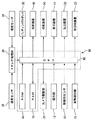
図2は、図1に示したゲーム装置の内部構成を示すブロック図である。図3は、図1に示したゲーム装置が備える視覚センサの内部構成を示すブロック図である。
Next, the internal configuration of the game apparatus shown in FIG. 1 will be described.
FIG. 2 is a block diagram showing an internal configuration of the game apparatus shown in FIG. FIG. 3 is a block diagram showing an internal configuration of a visual sensor provided in the game apparatus shown in FIG.
2つの視覚センサ28は、それぞれCMOSセンサカメラ20(図1参照)を備えており、所定の周期で(例えば、1msごとに)、野球ボールBを撮像し、得られた画像に基づいてオプティカルフローを生成する。
Each of the two
視覚センサ28は、図3に示すように、CMOSセンサカメラ20と、並列アンプ25と、A/D変換器アレイ26と、並列演算処理部27とを備えている。
CMOSセンサカメラ20は、N1個×N2個(例えば、128個×128個)の2次元状に配置されたCMOSセンサ20′を備えている。1つのCMOSセンサ20′は、CMOSセンサカメラ20における1画素に対応している。すなわち、CMOSセンサカメラ20の画素数はN1×N2画素である。
As shown in FIG. 3, the
The
並列アンプ25は、N2個のチャージアンプ25′を備えている。チャージアンプ25′は、N1個のCMOSセンサ20′から出力された電荷を電圧信号に変換する。
A/D変換器アレイ26は、N2個のA/D変換器26′を備えている。1個のA/D変換器26′は、1個のチャージアンプ25′からの出力信号をA/D変換する。
並列演算処理部27は、N1個×N2個の2次元状に配置された演算素子27′を備えている。並列演算処理部27の演算素子27′は、CMOSセンサカメラ20のCMOSセンサ20′と1対1で対応しており、その内部に演算素子27′の位置、すなわち、CMOSセンサカメラ20の画素位置に対応する位置情報を保持している。並列演算処理部27は、A/D変換器26′から出力されるデジタル信号に基づいて、SIMD型並列演算を行い、オプティカルフローを生成する。オプティカルフローは、CMOSセンサカメラ20により撮像された画像におけるXY座標系の複数のベクトルによって各画素の移動方向及び移動速度が示されるものである。並列演算処理部27は、生成したオプティカルフローをステレオ処理部29に供給する。当該技術については、従来公知の技術であり、例えば、特開2000−299820号公報、特開平10−145680号公報、特開平7−177435号公報等において詳述されているので、ここでの説明は省略する。
The
The A /
The parallel
2つの視覚センサ28は、所定の周期で、野球ボールBの撮像を行ってオプティカルフローを生成する。2つの視覚センサ28は、ステレオ処理部29と接続されており、ステレオ処理部29は、2つの視覚センサ28により生成されたオプティカルフローに基づいて、所定の周期で、野球ボールBの3次元位置を算出する。3次元位置は、XYZ座標によって表される。なお、オプティカルフローから3次元位置を演算する技術については、従来公知の技術であり、例えば、特開2001−12946号公報等において詳述されているので、ここでの説明は省略する。
The two
ステレオ処理部29により所定の周期で算出された野球ボールBの3次元位置は、3次元位置を示すデータ(以下、3次元位置データともいう)として制御回路60のCPU66に供給され、制御回路60が備えるRAM70に保持される。その結果、RAM70には、1回の投球においてピッチャープレート3側からホームベース4側へ向けて移動する野球ボールBに関する複数の3次元位置データが保持される。
The three-dimensional position of the baseball B calculated by the
ROM68には、野球ボールBに関する複数の3次元位置データに基づいて、野球ボールBの軌道及び速度を算出する軌道算出プログラムが格納されている。軌道算出プログラムには、複数の3次元位置データに基づいて算出される野球ボールBの軌道及び速度を、当該軌道及び速度に影響を及ぼす外的要因(例えば、重力、空気抵抗等)に応じて補正する補正プログラムが含まれる。CPU66は、軌道算出プログラムを実行することにより、野球ボールBの軌道及び速度を算出する。
The
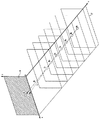
図4は、野球ボールBの軌道及び速度の演算と、野球ボールBの到達点及び到達時間の算出とに関する処理について説明するための概念図である。
仮想プレーフィールド2′は、ゲーム装置1におけるプレーフィールド2に対応するものであり、仮想プレーフィールド2′上に広がるXYZ座標系の仮想空間は、プレーフィールド2上の空間に対応している。従って、プレーフィールド2上においてピッチャープレート3側からホームベース4側へ向けて移動する野球ボールBの位置は、仮想プレーフィールド2′上の仮想空間においてXYZ座標によって表される。すなわち、上述したステレオ処理部29により所定の周期で算出される野球ボールBの3次元位置は、仮想プレーフィールド2′上の仮想空間におけるXYZ座標によって表される。
FIG. 4 is a conceptual diagram for explaining processing related to the calculation of the trajectory and speed of the baseball B and the calculation of the arrival point and arrival time of the baseball B.
The
図中、B1〜B7は、ピッチャープレート3側からホームベース4側へ向けて所謂変化球が放たれた際に、所定の周期で算出される野球ボールBの3次元位置を示している。 In the figure, B 1 to B 7 indicate the three-dimensional position of the baseball B calculated at a predetermined period when a so-called changing ball is released from the pitcher plate 3 side toward the home base 4 side. .
野球ボールBの3次元位置は、B1、B2、・・Bnの順に移動する。
CPU66は、野球ボールBの3次元位置B1〜Bnに基づいて、野球ボールBの軌道On及び速度を算出する。例えば、RAM70に、野球ボールBの3次元位置B1〜B5に関する3次元位置データが記憶された場合、CPU66は、ROM68に格納された軌道算出プログラムを実行することにより、野球ボールBの軌道として軌道O5を算出し、野球ボールBの速度を算出する。
Three-dimensional position of the baseball B is, B 1, B 2, moves in the order of · · B n.
CPU66 on the basis of the three-dimensional position B 1 .about.B n baseball B, and calculates the trajectory O n and the speed of the baseball B. For example, when the three-dimensional position data related to the three-dimensional positions B 1 to B 5 of the baseball ball B is stored in the
その後、野球ボールBの軌道が変化し、例えば、RAM70に、野球ボールBの3次元位置B1〜B7に関する3次元位置データが記憶された場合、CPU66は、ROM68に格納された軌道算出プログラムを実行することにより、野球ボールBの軌道として軌道O7を算出し、野球ボールBの速度を算出する。
このように、ゲーム装置1においては、野球ボールBが移動している間、所定の周期で、新たな3次元位置データがRAM70に記憶され、野球ボールBの軌道On及び速度が算出されるため、変化球が投げられた場合であっても、野球ボールBの軌道及び速度を算出することができる。
Thereafter, when the trajectory of the baseball ball B changes, for example, when the
Thus, in the game apparatus 1, while the baseball B is moving, at a predetermined period, a new three-dimensional position data is stored in
ゲーム装置1において、野球ボールBの軌道Onは、例えば、上記仮想空間のXYZ座標系に対応した変数X、Y、Zを含む1又は2以上の関数等で表される。また、野球ボールBの速度は、例えば、単位時間あたりの変数Yの変化量等で表される。
CPU66は、野球ボールBの軌道Onを表す関数から、到達点の位置(Y=0における野球ボールBの位置のX、Z座標)を算出し、野球ボールBの速度から、野球ボールBが到達点に達する到達時間を算出する。
In the game apparatus 1, the trajectory O n baseball B, for example, variables corresponding to the XYZ coordinate system of the virtual space X, Y, represented by such as one or more functions including Z. Further, the speed of the baseball B is represented by, for example, the amount of change in the variable Y per unit time.
CPU66 from the function representing the trajectory O n baseball B, (X position of the baseball B in Y = 0, Z coordinates) position of the arrival point is calculated, the speed of the baseball B, baseball ball B The arrival time to reach the arrival point is calculated.
このようにして算出された野球ボールBの軌道及び速度と、野球ボールBの到達点及び到達時間とは、制御回路60のRAM70にデータ(以下、球挙動データともいう)として保持される。
The trajectory and speed of the baseball B calculated in this way and the arrival point and arrival time of the baseball B are stored as data (hereinafter also referred to as ball behavior data) in the
ROM68は、ゲームに関する各種のプログラムを記憶する。例えば、野球ボールBに関する複数の3次元位置データに基づいて野球ボールBの軌道及び速度を算出する軌道算出プログラム、RAM70に保持される球挙動データに基づいて野球ボールBに追従するようにカメラ駆動部24を駆動させる制御を行うための球追従プログラム、バッティングロボット30のスイング動作を制御するためのスイング制御プログラム、表示装置11の表示制御プログラム、投影装置40、50の表示制御プログラム、その他のゲーム進行に係る処理を実行する制御プログラム等を記憶する。
The
スイング制御プログラムには、バッティングロボット30のスイング動作をバット31の時間軌道により与える基本スイング制御プログラムと、RAM70に保持された球挙動データに基づいてバット31の軌道を実時間的に補正するスイング補正プログラムと、スイング演出(バッティングを行う前の打者のスイング)のためのバッティングロボット30のスイング動作をバット31の時間軌道により与えるスイング演出プログラムとが含まれる。スイング演出プログラムと基本スイング制御プログラムとは、互いにフォームの異なる複数の打者の各々について個別に設定されているものであり、各打者のスイングを真似てバット31のスイングを行うためのものである。
The swing control program includes a basic swing control program that gives the swing motion of the
ROM68は、ゲームに関する各種のデータを記憶する。例えば、表示装置11に表示される画像を示す画像データ、投影装置40によりスクリーン41に表示される打者画像42等を示す画像データ、投影装置50によりスクリーン51に表示される標的領域52や捕手、審判員等の画像を示す画像データ等を記憶する。打者画像42を示す画像データは、互いにフォームの異なる複数の打者の各々について個別にROM68に記憶されている。
The
RAM70は、ゲームに用いられる各種の変数等のデータを一時的に保持する。例えば、野球ボールBの3次元位置データ、球挙動データ、標的選択データ、打者選択データ等を記憶する。
The
制御回路60には、カメラ駆動部24が接続されている。カメラ駆動部24は、上述したCMOSセンサカメラ20を旋回させるためのモータや、モータ駆動回路等を備えている。
CPU66は、RAM70に保持された球挙動データに基づいて、カメラ駆動部24に駆動信号を送信する。カメラ駆動部24は、当該駆動信号に応じて動作し、野球ボールBに追従するようにCMOSセンサカメラ20を旋回させる。
The
The
制御回路60には、操作部12と、複数個の球検知センサ53と、貨幣識別器21とが接続されている。
操作部12が操作された場合には制御回路60に操作内容に応じた所定の操作信号が供給される。球検出センサ53は、スクリーン51に格子状に配列されており、スクリーン51の前面に衝突した野球ボールBを検出可能である。野球ボールBを検出した球検出センサ53は制御回路60に検出信号を送信する。
貨幣識別器21は、貨幣投入口13に投入された正規の貨幣を検出した際、検出信号を制御回路60に送信する。
An
When the
The
制御回路60には、バッティングロボット30が接続されている。
バッティングロボット30は、4関節を有するアームが台座に設けられ、アームの先端に打具としてのバット31が取り付けられたものである。各関節はワイヤによって駆動される。すなわち、台座近傍にはアクチュエータが設けられており、アクチュエータからの動力がワイヤによって伝達されて各関節が駆動される。
CPU66は、駆動信号を送信してバッティングロボット30のスイング動作を制御する制御手段として機能するものである。なお、複数の関節を有するアームを備え、当該アームがワイヤによって駆動されるロボット、すなわち、ワイヤ駆動式のロボットについては、従来公知のものであるから、ここでの説明は省略する。
A batting
The batting
The
制御回路60には、投影装置40、50が接続されている。投影装置40、50はプロジェクタである。投影装置40は、打者画像42をスクリーン41上に表示するものである。投影装置50は、標的領域52をスクリーン51上に表示するものであり、その他にも捕手や審判員等を示す画像をスクリーン51上に表示する。
制御回路60には、表示装置11が接続されている。表示装置11には、ゲーム条件の入力をプレーヤPに促すための各種の画像、例えば、スクリーン51上に標的領域52を表示するか非表示とするかを選択するための指示を入力する標的表示/非表示選択画像、スクリーン51上に表示される標的領域52の種類を選択するための指示を入力する標的種類選択画像、プレーヤPの対戦相手となる打者を選択するための打者選択画像等が表示される。
The
制御回路60には、払出装置22が接続されている。払出装置22は、所定額の貨幣が貨幣投入口13に投入されたときに、球貸出装置10内に貯留された野球ボールBを所定数だけ球貸出口14を介して球貯留皿15に払い出すものである。プレーヤPは払い出された野球ボールBを用いてピッチングゲームを行う。
The
制御回路60には、球回収装置23が接続されている。球回収装置23は、フィールド2を転がって排出口16を通過してフィールド2の下部へ排出された野球ボールBを、球貸出装置10内まで移送するための移送装置(例えば、コンベア等)である。球回収装置23は、ゲームが開始された際に作動し、ゲーム終了時に停止する。球回収装置23によって移送された野球ボールBは球貸出装置10内に貯留される。
The
次に、上述した構成を有するゲーム装置1において行われる処理について説明することとする。
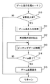
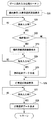
図5は、ゲーム進行処理のサブルーチンを示すフローチャートである。
このサブルーチンは、予め実行されているメインルーチンから所定のタイミングで呼び出されて実行されるサブルーチンである。
Next, processing performed in the game apparatus 1 having the above-described configuration will be described.
FIG. 5 is a flowchart showing a subroutine of game progress processing.
This subroutine is called and executed at a predetermined timing from a main routine that is executed in advance.
まず、CPU66は、貨幣投入口13に所定額の貨幣が投入されたか否かを判断する(ステップS10)。この処理において、CPU66は、貨幣識別器21から所定額の貨幣を識別した旨の検出信号を受信した場合には、貨幣投入口13に貨幣が投入されたと判断する。このとき、貨幣識別器21は、プレーヤPにより投入された貨幣を識別する貨幣識別手段として機能する。
貨幣が投入されていないと判断した場合には、本サブルーチンを終了する。
First, the
If it is determined that no money has been inserted, this subroutine is terminated.
次に、CPU66は、ゲーム条件入力処理を実行する(ステップS11)。この処理では、後で図6を用いて詳述するが、プレーヤPによる操作部12の操作に基づいて、標的領域の表示/非表示の選択と、表示される標的領域の種類の選択と、打者の選択とが行われる。
Next, the
次に、所定数の野球ボールBの払い出しを行う(ステップS12)。この処理において、CPU66は、払出装置22に駆動信号を送信する。払出装置22は、当該駆動信号を受信すると、球貸出装置10内に貯留された野球ボールBを所定数(例えば、10球)だけ球貸出口14から球貯留皿15に払い出す処理を行う。このとき、払出装置22は、貨幣識別器(貨幣識別手段)21により識別された貨幣の額に応じた数の野球ボールBを払い出す球払出手段として機能する。
プレーヤPは、球貯留皿15に払い出された野球ボールBを用いて、ピッチングゲームを行う。
Next, a predetermined number of baseballs B are paid out (step S12). In this process, the
The player P plays a pitching game using the baseball ball B paid out to the
次に、ピッチングゲーム処理を行う(ステップS13)。ピッチングゲームは、プレーヤが1球の野球ボールBを投球することにより行われるゲームである。従って、ステップS12において10球の野球ボールBが払い出された場合、プレーヤは、10回のピッチングゲームを行うことができる。なお、ピッチングゲーム処理については、後で図7を用いて詳述することにする。 Next, a pitching game process is performed (step S13). The pitching game is a game played when a player throws one baseball B. Therefore, when 10 baseballs B are paid out in step S12, the player can play 10 pitching games. The pitching game process will be described later in detail with reference to FIG.
次に、CPU66は、ゲームが終了したか否かを判断する(ステップS14)。ゲームが終了したか否かについては、所定回数のピッチングゲームが終了したか否か、又は、操作部12を介してゲームを終了する旨の指示が入力されたか否かにより判断する。
また、所定回数のピッチングゲームが終了したか否かについては、RAM70に所定数のゲーム結果が記憶されたか否かにより判断する。
ゲームが終了していないと判断した場合、処理をステップS13に戻す。
Next, the
Further, whether or not the predetermined number of pitching games have been completed is determined based on whether or not a predetermined number of game results are stored in the
If it is determined that the game has not ended, the process returns to step S13.
ステップS14において、ゲームが終了したと判断した場合、CPU66は、表示装置11にゲーム結果を示す画像を表示する処理を行い、本サブルーチンを終了する(ステップS15)。ゲーム結果を示す画像には、例えば、ストライク数、ボール数、被安打数等を示す画像が含まれる。
If it is determined in step S14 that the game has ended, the
図6は、図5に示したサブルーチンのステップS11において呼び出されて実行されるゲーム条件入力処理のサブルーチンを示すフローチャートである。
まず、CPU66は、標的表示/非表示選択画像を表示装置11に表示する処理を行う(ステップS20)。標的表示/非表示選択画像は、スクリーン51上に標的領域52を表示するか非表示とするかを選択するための指示の入力を可能とする画像である。
この標的表示/非表示選択画像が表示装置11に表示されているとき、プレーヤPは、操作部12を操作し、スクリーン51上に標的領域52を表示するか非表示とするかを選択するための指示の入力を行うことができる。
このとき、操作部12は、標的領域52の表示又は非表示を選択する旨の指示を入力する第1指示入力手段として機能する。
FIG. 6 is a flowchart showing a subroutine of game condition input processing that is called and executed in step S11 of the subroutine shown in FIG.
First, the
When the target display / non-display selection image is displayed on the
At this time, the
次に、CPU66は、操作部12を介してプレーヤPより指示の入力があったか否かを判断する(ステップS21)。指示の入力がなかったと判断した場合、処理をステップS21に戻す。一方、指示の入力があったと判断した場合、CPU66は、当該指示がスクリーン51上に標的領域52を表示する旨の指示であるか否かを判断する(ステップS22)。標的領域52を表示する旨の指示ではない、すなわち、標的領域52を非表示とする旨の指示であった場合には、処理をステップS26に移す。
Next, the
ステップS22において、入力された指示が標的領域52を表示する旨の指示であると判断した場合には、標的種類選択画像を表示装置11に表示する処理を行う(ステップS23)。標的種類選択画像は、スクリーン51上に表示される標的領域52の種類を選択するための指示の入力を可能とする画像である。
標的領域52としては、例えば、ストライクゾーンに対応した標的領域、特定のコース(外角低めのコース)に対応した標的領域等を挙げることができ、標的種類選択画像には、これらの標的領域を選択するための選択肢が含まれる。
この標的種類選択画像が表示装置11に表示されているとき、プレーヤPは、操作部12を操作し、スクリーン51上に表示される標的領域52の種類を選択するための指示の入力を行うことができる。
このとき、操作部12は、複数種類の標的領域のなかから、いずれか1の標的領域を選択する旨の指示を入力する第2指示入力手段として機能する。
If it is determined in step S22 that the input instruction is an instruction to display the
Examples of the
When the target type selection image is displayed on the
At this time, the
次に、CPU66は、操作部12を介してプレーヤPより指示の入力があったか否かを判断する(ステップS24)。指示の入力がなかったと判断した場合、処理をステップS24に戻す。一方、指示の入力があったと判断した場合、CPU66は、選択された標的領域を示す標的選択データを生成し、RAM70に記憶する(ステップS25)。
Next, the
ステップS22において、標的領域52を非表示とする旨の指示が入力されたと判断した場合、又は、ステップS25の処理を実行した場合、次に、CPU66は、打者選択画像を表示装置11に表示する処理を行う(ステップS26)。打者選択画像は、プレーヤPの対戦相手となる打者を選択するための画像であり、打者選択画像には、例えば、フォームの異なる複数のプロ野球選手等を示す画像が選択肢として含まれる。この打者選択画像が表示装置11に表示されているとき、プレーヤPは、操作部12を操作し、対戦相手となる打者を選択するための指示の入力を行うことができる。
このとき、操作部12は、互いに異なるフォームが設定された複数の打者のなかから、いずれか1の打者を対戦相手として選択する旨の指示を入力する第3指示入力手段として機能する。なお、ピッチングゲームを行う際には、選択された打者を示す打者画像42がスクリーン41上に表示され、選択された打者に設定されたフォームでバッティングロボット30によってバット31がスイングされる。
If it is determined in step S22 that an instruction to hide the
At this time, the
次に、CPU66は、操作部12を介して打者を選択する旨の指示の入力があったか否かを判断する(ステップS27)。指示の入力がなかったと判断した場合、処理をステップS27に戻す。一方、指示の入力があったと判断した場合、CPU66は、選択された打者を示す打者選択データを生成し、RAM70に記憶する(ステップS28)。その後、本サブルーチンを終了する。
Next, the
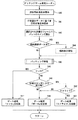
図7は、図5に示したサブルーチンのステップS13において呼び出されて実行されるピッチングゲーム処理のサブルーチンを示すフローチャートである。
まず、CPU66は、投影装置50を駆動させ、スクリーン51上に捕手や審判員等を示す画像を表示させる処理を開始する(ステップS40)。
投影装置50は、本サブルーチンが実行されている間、所定の動作を行う態様で捕手や審判員等を示す画像をスクリーン51上に表示し、本サブルーチンが終了する際に、捕手や審判員等を示す画像の表示を終了する。
FIG. 7 is a flowchart showing a pitching game process subroutine called and executed in step S13 of the subroutine shown in FIG.
First, the
The
次に、CPU66は、投影装置40を駆動させ、RAM70に記憶された打者選択データに基づいて、打者画像42をスクリーン41に表示させる処理を開始する(ステップS41)。投影装置40は、本サブルーチンが実行されている間、所定の動作を行う態様で打者画像42をスクリーン41上に表示する。バッティングロボット30によってバット31のスイングが行われる際には、投影装置40は、選択された打者に設定されたフォームでスイング動作を行うように打者画像42を表示する。投影装置40は、本サブルーチンが終了する際に、打者画像42の表示を終了する。
投影装置40は、選択された打者を示す打者画像42を表示する打者画像表示手段として機能するものである。
Next, the
The
次に、CPU66は、バッティングロボット30を駆動させ、RAM70に記憶された打者選択データに基づいて、選択された打者のフォームでバット31のスイング演出を行う(ステップS42)。この処理において、CPU66は、RAM70に記憶された打者選択データに基づいて、ROM68に記憶されている複数種類のスイング演出プログラムのなかから、選択された打者に応じたスイング演出プログラムを選択し、このスイング演出プログラムに基づいてバッティングロボット31によるバット31のスイングを制御する。
Next, the
次に、CPU66は、RAM70に標的選択データが記憶されているか否かを判断する(ステップS43)。RAM70に標的選択データが記憶されていると判断した場合、CPU66は、この標的選択データに基づいて、投影装置50により標的領域52をスクリーン51に表示させる処理を開始する(ステップS44)。
投影装置50は、本サブルーチンが実行されている間、標的領域52を示す画像をスクリーン51上に表示し、本サブルーチンが終了する際に、標的領域52を示す画像の表示を終了する。
投影装置50は、プレーヤPによって投げられる野球ボールBの標的となる標的領域52を表示する標的領域表示手段として機能するものである。
Next, the
The
The
次に、CPU66は、バッティング処理を実行する(ステップS45)。この処理では、後で図8を用いて詳述するが、プレーヤPにより投げられた野球ボールBに対するバッティングロボット30によるバット31のスイングが行われる。
Next, the
次に、CPU66は、バッティングロボット30によってヒットが打たれたか否かを判断する(ステップS46)。ヒットが打たれたか否かの判断は、例えば、RAM70に保持される球挙動データに基づいて、野球ボールBの移動方向の変化等を検出することにより行われる。バッティングロボット30によってヒットが打たれたと判断した場合、CPU66は、ゲーム結果が「ヒット」である旨をデータとしてRAM70に記憶し(ステップS47)、本サブルーチンを終了する。
Next, the
ステップS46において、バッティングロボット30によってヒットが打たれていないと判断した場合、CPU66は、球検出センサ53により野球ボールBが検出されたか否かを判断する(ステップS48)。この処理において、CPU66は、スクリーン51に格子状に配列された複数の球検出センサ53のうち、いずれか1の球検出センサ53から、検出信号を受信したか否かを判断する。
If it is determined in step S46 that no hit has been hit by the batting
ステップS48において、球検出センサ53により野球ボールBが検出されていないと判断した場合、CPU66は、ゲーム結果が「ボール」である旨をデータとしてRAM70に記憶し(ステップS49)、本サブルーチンを終了する。
When it is determined in step S48 that the baseball B is not detected by the
ステップS48において、球検出センサ53により野球ボールBが検出されたと判断した場合、CPU66は、ストライクであったか否かを判断する(ステップS50)。ストライクであったか否かの判断は、ストライクゾーンに相当する領域に設置された球検出センサ53から検出信号を受信したか否かにより行われる。
すなわち、ストライクゾーンに相当する領域に設置された球検出センサ53から検出信号を受信した場合には、ストライクと判断する一方、ストライクゾーンに相当する領域以外の領域に設置された球検出センサ53から検出信号を受信した場合には、ボールと判断するのである。
In step S48, when it is determined that the baseball B is detected by the
That is, when a detection signal is received from the
ステップS50において、ストライクではないと判断した場合、CPU66は、ゲーム結果が「ボール」である旨をデータとしてRAM70に記憶し(ステップS49)、本サブルーチンを終了する。一方、ステップS50において、ストライクであると判断した場合、CPU66は、ゲーム結果が「ストライク」である旨をデータとしてRAM70に記憶し(ステップS51)、本サブルーチンを終了する。
If it is determined in step S50 that the game is not a strike, the
図8は、図7に示したサブルーチンのステップS45において呼び出されて実行されるバッティング処理のサブルーチンを示すフローチャートである。
まず、CPU66は、ステレオ処理部29から3次元位置データが入力されたか否かを判断する(ステップS60)。ステレオ処理部29から3次元位置データの入力が開始されたということは、プレーヤPによって投げられた野球ボールBがCMOSセンサカメラ20によって捕捉されたということである。
FIG. 8 is a flowchart showing a batting process subroutine that is called and executed in step S45 of the subroutine shown in FIG.
First, the
なお、図中には示していないが、最初にステレオ処理部29から3次元位置データが入力されると、CPU66は、カメラ駆動部24に駆動信号を送信し、当該駆動信号を受信したカメラ駆動部24は、野球ボールBに追従するようにCMOSセンサカメラ20を旋回させる。CMOSセンサカメラ20は、野球ボールBに追従するように旋回しながら1ms程度のフレームスパンで野球ボールBを撮像する。CMOSセンサカメラ20を含む視覚センサ28はオプティカルフローを生成し、ステレオ処理部29は、オプティカルフローから野球ボールBの3次元位置データを生成し、制御回路60に供給する。
従って、最初にステレオ処理部29から3次元位置データが供給されると、その後、所定の周期(例えば、1ms毎)でステレオ処理部29から3次元位置データが供給されることになる。
このとき、CMOSセンサカメラ20は、標的(例えば、標的領域52)に向けて投げられた野球ボールBを撮像する球撮像手段として機能する。
Although not shown in the figure, when three-dimensional position data is first input from the
Therefore, when the three-dimensional position data is first supplied from the
At this time, the
ステップS60において、ステレオ処理部29から3次元位置データが供給されていないと判断した場合、処理をステップS60に戻す。一方、ステップS60において、ステレオ処理部29から3次元位置データが供給されたと判断した場合、CPU66は、RAM70に3次元位置データを保持する(ステップS61)。なお、3次元位置データは、1回のピッチングゲームにおいては、ステレオ処理部29から供給されるごとに累積的にRAM70に保持され、ピッチングゲームが終了した際に消去される。
If it is determined in step S60 that the three-dimensional position data is not supplied from the
次に、CPU66は、所定数の3次元位置データがRAM70に保持されているか否かを判断する(ステップS62)。所定数の3次元位置データがRAM70に保持されていないと判断した場合、処理をステップS60に戻す。
一方、所定数の3次元位置データがRAM70に保持されていると判断した場合、CPU66は、ROM68に格納された軌道算出プログラムを実行し、RAM70に保持されている複数の3次元位置データに基づいて、野球ボールBの軌道及び速度を算出し、さらに、野球ボールBの到達点及び到達時間を算出する(ステップS63)。この処理については、図4を用いて既に説明済であるので、ここでの説明は省略する。ステップS63の処理を実行するとき、CPU66は、算出手段として機能する。
Next, the
On the other hand, if it is determined that a predetermined number of three-dimensional position data is held in the
次に、CPU66は、ステップS62において算出された野球ボールBの軌道及び速度並びに到達点及び到達時間を示すデータを生成し、球挙動データとしてRAM70に記憶する(ステップS64)。
次に、CPU66は、バッティングロボット30がバット31のスイング中であるか否かを判断する(ステップS65)。バッティングロボット30がバット31のスイング中ではないと判断した場合、CPU66は、打者の動作を選択する(ステップS66)。打者の動作としては、例えば、打つ動作、空振りする動作、見送る動作等がある。この処理において、CPU66は、RAM70に記憶された球挙動データから野球ボールBのコースを判別し、野球ボールBのコースに応じて打者の動作を設定する。例えば、野球ボールBのコースがストライクゾーンの中央部分であれば、打つ動作を選択し、野球ボールBのコースが外角又は内角の高め又は低めであれば、空振りする動作を選択し、野球ボールBのコースがストライクゾーンに入っていなければ、見送る動作を選択する。ピッチングゲームにおいては、選択された動作を行う態様で打者画像42が表示され、バッティングロボット30は選択された動作を行うようにバット31をスイングする。
なお、打者の動作の決定方法は上述した例に限定されるものではなく、例えば、抽選によって決定することとしてもよく、野球ボールBの速度によって決定することとしてもよい。
Next, the
Next, the
The method for determining the batter's movement is not limited to the above-described example. For example, the determination may be made by lottery or by the speed of the baseball B.
次に、CPU66は、選択した打者の動作が、見送る動作であるか否かを判断する(ステップS67)。選択した打者の動作が、見送る動作であると判断した場合、CPU66は、投影装置40によってスクリーン41上に、見送る動作を行う態様の打者画像42を表示し(ステップS68)、本サブルーチンを終了する。この場合、バッティングロボット30はバット31のスイング動作は行わない。
Next, the
ステップS68において、選択した打者の動作が、見送る動作ではないと判断した場合、次に、CPU66は、選択した打者の動作が、空振りする動作であるか否かを判断する(ステップS69)。選択した打者の動作が、空振りする動作であると判断した場合には、CPU66は、投影装置40によってスクリーン41上に、空振りする動作を行う態様の打者画像42を表示する(ステップS71)。
次に、CPU66は、選択された打者に対応する基本スイング制御プログラムを実行し、バッティングロボット30に駆動信号を送信してバット31をスイングさせる処理を行う。このとき、CPU66は、球挙動データに基づいて、野球ボールBに当たらない軌道でバット31をスイングするようにバッティングロボット30のスイング動作を制御する。その後、本サブルーチンを終了する。
If it is determined in step S68 that the selected batter's action is not a see-off action, the
Next, the
ステップS69において、選択した打者の動作が、空振りする動作ではないと判断した場合、すなわち、打つ動作であると判断した場合、CPU66は、投影装置40によってスクリーン41上に、打つ動作を行う態様の打者画像42を表示する(ステップS73)。
ステップS68、S71及びS73の処理を実行するとき、CPU66は、打者画像表示制御手段として機能する。
次に、CPU66は、選択された打者に対応する基本スイング制御プログラムを実行し、バッティングロボット30に駆動信号を送信し、バット31のスイングを開始する。このとき、球挙動データに基づいて、野球ボールBに当たる軌道でバット31をスイングするようにバッティングロボット30のスイング動作を開始させる。その後、処理をステップS74に進める。
In step S69, when it is determined that the selected batter's motion is not an idling motion, that is, when it is determined that the motion is a striking motion, the
When executing the processes of steps S68, S71 and S73, the
Next, the
ステップS74においては、バッティングロボット30のスイング動作が終了したか否かを判断する(ステップS75)。スイング動作が終了したと判断した場合には、本サブルーチンを終了する。一方、スイング動作が終了していないと判断した場合、処理をステップS60に戻し、処理をステップS60〜S65まで進める。この場合、ステップS65において、CPU66は、スイング中であると判断する。
In step S74, it is determined whether or not the swing motion of the
ステップS65において、スイング中であると判断した場合、CPU66は、先にRAM70に記憶されていた古い球挙動データと、新たに生成された球挙動データとに基づいて、野球ボールBの軌道が変化したか否かを判断する(ステップS75)。
野球ボールBの軌道が変化したと判断した場合、CPU66は、ROM68に格納されたスイング補正プログラムを実行し、バッティングロボット30によりスイングされるバット31の軌道を変化させる(ステップS76)。このように野球ボールBの軌道の変化に応じて実時間的にバット31の軌道を変化させることにより、変化球が投げられた場合であってもバッティングロボット30はバット31を野球ボールBに当てることができる。
その後、上述したステップS74に処理を進める。
If it is determined in step S65 that the swing is in progress, the
When determining that the trajectory of the baseball B has changed, the
Thereafter, the process proceeds to step S74 described above.
以上、ゲーム装置1によれば、プレーヤPが標的(例えば、標的領域52)に向けて投げた野球ボールBがバット31によって打ち返されるため、プレーヤPに対して、打者と対戦しているような感覚を抱かせることが可能な興趣性に富んだゲームを提供することができる。
As described above, according to the game apparatus 1, the baseball ball B thrown by the player P toward the target (for example, the target area 52) is returned by the
なお、上述した実施形態では、野球を題材としたゲーム装置について説明したが、本発明のゲーム装置は、例えば、テニス、卓球、バトミントン等、各種の球技を題材とすることが可能である。 In the above-described embodiment, the game device based on baseball has been described. However, the game device of the present invention can be based on various ball games such as tennis, table tennis, and badminton.
1 ゲーム装置
2 フィールド
3 ピッチャープレート
4 ホームベース
10 球貸出装置
11 表示装置
12 操作部
13 貨幣投入口
14 球貸出口
15 球貯留皿
20 CMOSセンサカメラ
20′ CMOSセンサ
21 貨幣識別器
22 払出装置
23 球回収装置
24 カメラ駆動部
25 並列アンプ
25′ チャージアンプ
26 A/D変換器アレイ
26′ A/D変換器
27 並列演算処理部
27′ 演算素子
28 視覚センサ
29 ステレオ処理部
30 バッティングロボット
31 バット
40、50 投影装置
41、51 スクリーン
42 打者画像
52 標的領域
53 球検知センサ
60 制御回路
66 CPU
68 ROM
70 RAM
DESCRIPTION OF SYMBOLS 1
68 ROM
70 RAM
Claims (6)
前記球を打ち返すための打具をスイングさせる駆動手段と、
前記標的に向けて放たれた球を撮像する球撮像手段と、
前記球撮像手段により撮像された前記球の画像に基づいて、前記球の軌道及び速度を演算し、前記球の到達点及び到達時間を算出する算出手段と、
前記算出手段による算出結果に基づいて、前記打具が前記到達時間に前記到達点を通過するように、前記駆動手段による前記打具のスイングを制御する制御手段と
を備えたことを特徴とするゲーム装置。 Target area display means for displaying a target area to be a target of a sphere released by the player;
Driving means for swinging a hitting tool for hitting the ball;
Sphere imaging means for imaging a sphere released toward the target;
Calculation means for calculating the trajectory and speed of the sphere based on the image of the sphere imaged by the sphere imaging means, and calculating the arrival point and arrival time of the sphere;
Control means for controlling the swing of the hitting tool by the driving means so that the hitting tool passes the arrival point at the arrival time based on the calculation result by the calculating means. Game device.
前記貨幣識別手段により識別された貨幣の額に応じた数の球を払い出す球払出手段と
を備えたことを特徴とする請求項1に記載のゲーム装置。 Money identifying means for identifying money inserted by the player;
The game apparatus according to claim 1, further comprising a ball payout unit that pays out a number of balls according to the amount of money identified by the money identification unit.
前記標的領域表示手段は、前記第1指示入力手段により入力された指示に応じて、前記標的領域の表示又は非表示を行うことを特徴とする請求項1又は2に記載のゲーム装置。 Comprising first instruction input means for inputting an instruction to select display or non-display of the target area;
The game apparatus according to claim 1, wherein the target area display unit displays or hides the target area in accordance with an instruction input by the first instruction input unit.
前記標的領域表示手段は、前記第2指示入力手段により入力された指示に応じて、選択された種類の標的領域の表示を行うことを特徴とする請求項1〜3のいずれか1に記載のゲーム装置。 A second instruction input means for inputting an instruction to select any one target area from the plurality of types of target areas;
The target area display unit displays a selected type of target area in accordance with an instruction input by the second instruction input unit. Game device.
前記制御手段は、前記第3指示入力手段により入力された指示に応じて、選択された打者のフォームで打具をスイングするように、前記駆動手段による前記打具のスイングを制御することを特徴とする請求項1〜4のいずれか1に記載のゲーム装置。 A third instruction input means for inputting an instruction to select any one batter as an opponent from a plurality of batters having different forms;
The control means controls the swing of the hitting tool by the driving means so as to swing the hitting tool in the form of the selected batter according to the instruction input by the third instruction input means. The game device according to claim 1.
選択された打者を示す打者画像を表示する打者画像表示手段と、
前記駆動手段による打具のスイングにあわせて、選択された打者が当該打者に設定されたフォームでスイングするように、当該打者画像の表示制御を行う打者画像表示制御手段と
を備えたことを特徴とする請求項1〜5のいずれか1に記載のゲーム装置。 A third instruction input means for inputting an instruction to select any one batter as an opponent from a plurality of batters set with different forms;
Batter image display means for displaying a batter image indicating the selected batter;
Batter image display control means for performing display control of the batter image so that the selected batter swings in the form set for the batter according to the swing of the hitting tool by the driving means. The game device according to claim 1.
Priority Applications (1)
| Application Number | Priority Date | Filing Date | Title |
|---|---|---|---|
| JP2004119116A JP2005296442A (en) | 2004-04-14 | 2004-04-14 | Game device |
Applications Claiming Priority (1)
| Application Number | Priority Date | Filing Date | Title |
|---|---|---|---|
| JP2004119116A JP2005296442A (en) | 2004-04-14 | 2004-04-14 | Game device |
Publications (1)
| Publication Number | Publication Date |
|---|---|
| JP2005296442A true JP2005296442A (en) | 2005-10-27 |
Family
ID=35328696
Family Applications (1)
| Application Number | Title | Priority Date | Filing Date |
|---|---|---|---|
| JP2004119116A Withdrawn JP2005296442A (en) | 2004-04-14 | 2004-04-14 | Game device |
Country Status (1)
| Country | Link |
|---|---|
| JP (1) | JP2005296442A (en) |
Cited By (3)
| Publication number | Priority date | Publication date | Assignee | Title |
|---|---|---|---|---|
| CN108607210A (en) * | 2018-05-22 | 2018-10-02 | 郑州轻工业学院 | A kind of improved intelligent tennis ball training system |
| WO2020071406A1 (en) * | 2018-10-02 | 2020-04-09 | パナソニック インテレクチュアル プロパティ コーポレーション オブ アメリカ | Information provision method |
| CN112789485A (en) * | 2018-10-02 | 2021-05-11 | 松下电器(美国)知识产权公司 | Information providing method |
-
2004
- 2004-04-14 JP JP2004119116A patent/JP2005296442A/en not_active Withdrawn
Cited By (8)
| Publication number | Priority date | Publication date | Assignee | Title |
|---|---|---|---|---|
| CN108607210A (en) * | 2018-05-22 | 2018-10-02 | 郑州轻工业学院 | A kind of improved intelligent tennis ball training system |
| WO2020071406A1 (en) * | 2018-10-02 | 2020-04-09 | パナソニック インテレクチュアル プロパティ コーポレーション オブ アメリカ | Information provision method |
| CN112789649A (en) * | 2018-10-02 | 2021-05-11 | 松下电器(美国)知识产权公司 | Information providing method |
| CN112789485A (en) * | 2018-10-02 | 2021-05-11 | 松下电器(美国)知识产权公司 | Information providing method |
| JPWO2020071406A1 (en) * | 2018-10-02 | 2021-09-02 | パナソニック インテレクチュアル プロパティ コーポレーション オブ アメリカPanasonic Intellectual Property Corporation of America | Information provision method |
| US11688167B2 (en) | 2018-10-02 | 2023-06-27 | Panasonic Intellectual Property Corporation Of America | Information providing method |
| JP7394776B2 (en) | 2018-10-02 | 2023-12-08 | パナソニック インテレクチュアル プロパティ コーポレーション オブ アメリカ | Information provision method |
| CN112789649B (en) * | 2018-10-02 | 2024-10-18 | 松下电器(美国)知识产权公司 | Information provision method |
Similar Documents
| Publication | Publication Date | Title |
|---|---|---|
| US7223169B2 (en) | Program for controlling execution of a game, and a game machine for executing the program | |
| JP5286267B2 (en) | Game device, game program, and object operation method | |
| JP4619087B2 (en) | GAME PROGRAM AND GAME DEVICE | |
| JP5751594B2 (en) | Virtual golf simulation apparatus and method | |
| JP3443402B2 (en) | Computer-readable recording medium recording action game program, action game control device and method, action game program | |
| KR101494204B1 (en) | Screen baseball game system and batter, pitcher, catcher, and fielder mode realization metohd thereof | |
| TW201641143A (en) | A screen baseball game apparatus without temporal and spatial limitations | |
| EP1184059B1 (en) | Game machine | |
| CN108495691B (en) | Sensing device and sensing method used in baseball practice device, baseball practice device using the same, and control method thereof | |
| US20110172017A1 (en) | Game machine, game program, and game machine control method | |
| JP5396212B2 (en) | GAME DEVICE, GAME DEVICE CONTROL METHOD, AND PROGRAM | |
| TW202103759A (en) | Virtual golf simulation processing method and screen golf system using the same | |
| JP5811263B2 (en) | Virtual golf simulation apparatus and method thereof, and sensing apparatus and sensing method used therefor | |
| JP3619223B2 (en) | Game device | |
| JP2012101026A (en) | Program, information storage medium, game device, and server system | |
| KR101008595B1 (en) | Screen golf practice system | |
| KR102002006B1 (en) | Hybrid air hockey game apparatus and its control method | |
| KR20180085843A (en) | Swing analyzing device capable of correcting a swing posture and playing a game, and operation method thereof | |
| KR200240118Y1 (en) | Point Display Apparatus For Indoor Golf Exercising Field | |
| JP2005296442A (en) | Game device | |
| JP3894937B2 (en) | PROGRAM, INFORMATION STORAGE MEDIUM, AND GAME DEVICE | |
| JP2002320776A (en) | Program for controlling execution of game, and game device for executing this program | |
| KR20190133329A (en) | Attack and defensive manipulation screen Control method of baseball game system | |
| JPH08280864A (en) | Ball game exercising machine | |
| KR102025397B1 (en) | A screen baseball system in which operations are controlled according to the items used |
Legal Events
| Date | Code | Title | Description |
|---|---|---|---|
| A621 | Written request for application examination |
Effective date: 20061205 Free format text: JAPANESE INTERMEDIATE CODE: A621 |
|
| RD04 | Notification of resignation of power of attorney |
Free format text: JAPANESE INTERMEDIATE CODE: A7424 Effective date: 20070831 |
|
| A761 | Written withdrawal of application |
Effective date: 20081111 Free format text: JAPANESE INTERMEDIATE CODE: A761 |