本発明は、ご飯やポテト、おから等の食材を締め固めてお握りを製造することのできるお握り製造用具に関するものである。
The present invention relates to a hand grip manufacturing tool capable of manufacturing a hand grip by compacting ingredients such as rice, potato, and okara.
お握りの一般的な作り方は、所定量のご飯を手で握って球形や三角形等に形を整えるものであるが、勘でご飯の量を量り、勘で形状を整えることは意外と難しく、又、手にご飯が付着して手間が掛かるといった面倒さがあった。
The general way to make a handful is to hold a predetermined amount of rice with your hand and shape it into a sphere or triangle, etc., but it is surprisingly difficult to measure the amount of rice with the intuition and adjust the shape with the intuition, There was a hassle that rice was stuck on the hands and it took time.
そこで本発明者は特開平8−140602号において、実質的に線対称となる2つの面部を具えたベースプレートを有し、該ベースプレートの一面側の外周縁の全周囲に亘ってて所要高さの立壁が突設されており、該ベースプレートと立壁との間でご飯の収容部が形成される如くなされたお握り製造用具を提案した。そして該お握り製造用具を用いてお握りを製造するには、前記ベースプレートの上面部の全体を覆うようにフイルム状物を被せて後、前記収容部にご飯を収容し、該収容されたご飯を中央線(線対称の軸線)に沿って折り曲げるように前記フイルム状物の対向する周縁部分を持ち上げて絞る工程を経るものであり、これにより、フイルム状物で包装されたお握りを得ることができた。
In view of this, the present inventor disclosed in Japanese Patent Application Laid-Open No. 8-140602 has a base plate having two surface portions that are substantially line-symmetric, and has a required height over the entire circumference of the outer peripheral edge on one surface side of the base plate. There has been proposed a hand-grip manufacturing tool in which a standing wall is projected and a rice receiving portion is formed between the base plate and the standing wall. And in order to manufacture a grip using the grip manufacturing tool, after covering the whole upper surface portion of the base plate with a film-like material, the rice is stored in the storage portion, and the stored rice is placed in the center. The film was subjected to a process of lifting and squeezing the opposing peripheral portions of the film-like object so as to be bent along a line (axisymmetric axis), thereby obtaining a grip packaged with the film-like object. .
かかるお握り製造用具によるときは、前記ベースプレートと立壁との間で形成されたご飯の収容部に、フイルム状物を介してご飯を広げて収容すると、1個のお握りのご飯の量とお握りの展開状態の形が決まるため、その後に、このご飯を前記中央線で折り曲げるようにフイルム状物を絞ると、お握りの基本的な形と大きさが得られる。従って、お握りの形や大きさを、その後の簡単な握り方によって決定できる利点があった。
When using such a hand-grip manufacturing tool, when the rice is spread and accommodated in the rice storage portion formed between the base plate and the standing wall via a film-like material, the amount of rice per hand and the development of the hand-holding Since the shape of the state is determined, the basic shape and size of the hand grip can be obtained by squeezing the film-like material so that the rice is bent at the center line. Therefore, there is an advantage that the shape and size of the grip can be determined by a simple grip after that.
しかしながら、かかる従来のお握り製造用具によるときは、収容部に収容されているご飯を前記中央線で折り曲げるようにフイルム状物を絞るときに、ご飯が収容部から外れることによって該収容部による保形作用が解除されてしまう。その結果、お握りの最終的な形はフイルム状物を介しての手による握り方によって決められることになるが、前記収容部の形状通りに見栄え良く形を整えることは難しかった。
However, when such a conventional grip manufacturing tool is used, when the film-like object is squeezed so that the rice accommodated in the accommodating portion is bent at the center line, the rice is removed from the accommodating portion so that the shape is retained by the accommodating portion. The action is canceled. As a result, the final shape of the hand grip is determined by the way of gripping by hand through the film-like object, but it is difficult to arrange the shape nicely according to the shape of the housing portion.
又、炊きたて等の熱いご飯を締め固める際、フイルム状物を介するだけでは熱くて締め固めに困難が伴った。更に、製造されたお握りを持ち運ぶ際は、お握りの形状が崩れないようにこれを保護する必要から、お握りを容器に収容して持ち運ばざるを得なかった。
特開平8−140602号公報(4−5頁、図1−図7)
In addition, when hot rice such as freshly cooked rice is compacted, it is hot and difficult to compact only through the film-like material. Furthermore, when carrying the manufactured handgrip, it is necessary to protect the handgrip so that the shape of the handgrip does not collapse. Therefore, the handgrip must be carried in a container.
Japanese Patent Laid-Open No. 8-140602 (page 4-5, FIGS. 1 to 7)
本発明は、前記問題点に鑑みて開発されたものであり、見栄え良く形の整えられたお握りを容易に製造できると共に、お握りの完成と同時にお握りの包装状態が得られるお握り製造用具の提供を課題とするものである
The present invention has been developed in view of the above-mentioned problems, and provides a hand grip manufacturing tool that can easily manufacture a hand-grip with a good shape and can obtain a hand-wrapped state at the same time as the hand grip is completed. It is to be an issue
前記課題を解決するため、本発明は以下の手段を採用する。
即ち本発明に係るお握り製造用具は、上端開放の2個の収容器が開閉可能に連結され、且つ該2個の収容器が展開状態で実質的に線対称を呈する如く構成されたお握り製造用具であって、該収容器は、基片の一面側の外周縁に所要高さの立壁が突設され、該基片と立壁との間で、食材を収容する収容部が形成されると共に、該左右の収容器の向き合う立壁部分の縁部相互が屈曲部で連結されており、又両収容器を閉じるように前記屈曲部で折り曲げたときに、両収容器の開放端相互が略合致することを特徴とするものである。
In order to solve the above problems, the present invention employs the following means.
In other words, the hand grip manufacturing tool according to the present invention is configured so that two containers open at the upper end are connected to be openable and closable and the two containers are substantially line-symmetric in the deployed state. In the container, an upright wall having a required height protrudes from the outer peripheral edge of one surface side of the base piece, and a storage portion for containing food is formed between the base piece and the upright wall, The edges of the standing wall portions of the right and left containers are connected to each other by a bent portion, and when the two bent portions are folded so as to be closed, the open ends of the two containers are substantially matched. It is characterized by this.
前記お握り製造用具において、前記基片の少なくとも中央部分を撓み変形可能とするのがよい。併せて、前記立壁を撓み変形可能とするのがよい。この場合、該立壁を、周方向で見て途切れ状態に形成するのがよい。
In the grip manufacturing tool, at least a central portion of the base piece may be bent and deformable. In addition, it is preferable that the standing wall can be bent and deformed. In this case, it is preferable to form the standing wall in a discontinuous state when viewed in the circumferential direction.
又前記お握り製造用具において、前記基片が撓み変形できるように、前記基片に開口及び/又は切り目を形成するのがよい。
Further, in the hand grip manufacturing tool, it is preferable to form an opening and / or a cut in the base piece so that the base piece can be bent and deformed.
又前記お握り製造用具において、前記基片の中央部分に、少なくとも指先を嵌め入れることのできる開口を形成するのがよい。
In the hand grip manufacturing tool, it is preferable that an opening in which at least a fingertip can be fitted is formed in a central portion of the base piece.
又前記お握り製造用具において、前記基片の対向する縁間の全長に亘る状態で開口を形成し、該開口を並設することによって、隣り合う開口間に押圧片を形成するのがよい。
Further, in the hand grip manufacturing tool, it is preferable that an opening is formed over the entire length between the opposing edges of the base piece, and the pressing piece is formed between adjacent openings by arranging the openings side by side.
又前記お握り製造用具において、前記基片の対向する縁間の全長に亘る状態で切り目を形成し、該切り目を並設することによって、隣り合う切り目間に押圧片を形成するのがよい。
Further, in the hand grip manufacturing tool, it is preferable that a cut piece is formed over the entire length between the opposing edges of the base piece, and a press piece is formed between adjacent cuts by arranging the cuts side by side.
又前記お握り製造用具において、前記基片の対向する縁間の全長に亘る状態で、ジグザグ状に屈曲する開口を形成し、該開口を並設することによって、隣り合う開口間にジグザク状の押圧片を形成するのがよい。
In the hand grip manufacturing tool, a zigzag-shaped opening is formed between the adjacent openings by forming an opening that bends in a zigzag shape over the entire length between the opposing edges of the base piece. It is good to form a piece.
又前記お握り製造用具において、前記基片の対向する縁間の全長に亘る状態で、ジグザグ状に屈曲する切り目を形成し、該切り目を並設することによって、隣り合う切り目間にジグザク状の押圧片を形成するのがよい。
In the hand grip manufacturing tool, a zigzag-shaped cut is formed in a state extending over the entire length between the opposing edges of the base piece, and the zigzag-shaped press between adjacent cuts is formed by arranging the cuts in parallel. It is good to form a piece.
又前記お握り製造用具において、前記収容器は、平面視で三角形状を呈したものとし、該収容器の前記基片には、対向する傾斜縁間の全長に亘る状態で、三角形の高さ方向に所要間隔を置いてジグザグ状に屈曲する開口を並設することによって、隣り合う開口間にジグザク状の押圧片を形成するのがよい。
In the hand grip manufacturing tool, the container has a triangular shape in plan view, and the base piece of the container has a triangular height direction across the entire length between the opposing inclined edges. It is preferable to form zigzag-shaped pressing pieces between adjacent openings by arranging the openings that are bent in a zigzag shape at a necessary interval.
本発明に係るお握り製造用具のその他の態様は、上端開放の2個の収容器が開閉可能に連結され、且つ該2個の収容器が展開状態で実質的に線対称を呈する如く構成されており、該収容器は、基片の一面側の外周縁に所要高さの立壁が突設され、該基片と立壁との間で、食材を収容する収容部が形成されると共に、該左右の収容器の向き合う立壁部分の縁部相互が屈曲部で連結されており、又両収容器を閉じるように前記屈曲部で折り曲げたときに、一方の収容器の前記立壁の先側部分が他方の収容器の収容部内に入り込んだ状態となるように、該他方の収容器のサイズが稍拡大していることを特徴とするものである。
In another aspect of the handgrip manufacturing tool according to the present invention, two containers open at the upper end are connected to be openable and closable, and the two containers are configured to be substantially line symmetric in the deployed state. The container is provided with a standing wall having a required height projecting from the outer peripheral edge of one surface of the base piece, and a housing portion for containing food is formed between the base piece and the standing wall. The edges of the standing wall portions of the container are connected to each other by a bent portion, and when the two bent portions are folded so as to close both containers, the front side portion of the standing wall of one container is the other. The size of the other container is enlarged so as to be in a state of entering the container of the container.
又前記お握り製造用具において、前記左右の収容器の対向する立壁部分に、前記屈曲部から略等距離にある部位で、該立壁部分を幅方向に切断するための切り取り線を設け、該両収容器を閉じるように前記屈曲部で折り曲げたときに該両収容器に設けられた左右の切り取り線が略対向するように構成するのがよい。
Further, in the hand grip manufacturing tool, the opposing vertical wall portions of the left and right containers are provided with a cut line for cutting the vertical wall portion in the width direction at a portion that is substantially equidistant from the bent portion. It is preferable that the left and right cut lines provided in the two containers are substantially opposed when folded at the bent portion so as to close the container.
該切り取り線を設けるお握り製造用具において、前記基片の対向する縁間の全長に亘る状態で開口を形成し、該開口を並設することによって隣り合う開口間に押圧片を形成する場合、前記切り取り線を、前記押圧片が存する部分で設けることができる一方、前記切り取り線を、前記開口が存する部分で設けることもできる。
In the hand grip manufacturing tool provided with the cut line, when the opening is formed in a state extending over the entire length between the opposing edges of the base piece, and the pressing piece is formed between adjacent openings by arranging the openings, While the cut line can be provided at a portion where the pressing piece exists, the cut line can be provided at a portion where the opening exists.
又該切り取り線を設けるお握り製造用具において、前記基片の対向する縁間の全長に亘る状態で切り目を形成し、該切り目を並設することによって隣り合う切り目間に押圧片を形成する場合、前記切り取り線を、前記押圧片が存する部分で設けることができる一方、前記切り取り線を、前記切り目が存する部分で設けることもできる。
Further, in the hand grip manufacturing tool providing the cut line, when forming a cut in a state extending over the entire length between the opposing edges of the base piece, and forming a pressing piece between adjacent cuts by arranging the cuts in parallel, While the cut line can be provided at a portion where the pressing piece exists, the cut line can be provided at a portion where the cut exists.
又該切り取り線を設けるお握り製造用具において、対向する切り取り線相互を連結するように、前記基片にミシン目状の折り曲げ線を設けるのがよい。
なお本発明において「お握り」とは、ご飯以外の食材からなるものも含む概念である。
In the hand grip manufacturing tool provided with the cut line, a perforated fold line may be provided on the base piece so as to connect the cut lines facing each other.
In the present invention, “handful” is a concept that includes foods other than rice.
本発明は以下の如き優れた効果を奏する。
(1) 本発明に係るお握り製造用具1によるときは、2個の収容器にご飯等の食材を直接的に収容し、或いはご飯等の食材をフイルム状物を介在させて収容して後、両収容器を閉じるように屈曲部で折り曲げ、収容されたご飯等の上面相互を腹合せ状態とする工程を経て後、収容状態にある食材を収容器の外側から締め固めることによってお握りを製造できるため、お握りの形状を、収容器の形状に合致させて整えることが容易であり、従来とは異なり、見栄えの良いお握りを能率的に製造できることとなる。又、食材に手を触れることなくこれを締め固めることができるため、お握りを衛生的に製造できる。又、収容器が一定の断熱性を有するため、炊きたて等の熱いご飯を締め固めてお握りを製造する場合であっても、フイルム状物だけを介してお握りを締め固める前記従来のお握り製造における場合とは異なり、熱さをそれほど感じずに楽に締め固めることができる。
The present invention has the following excellent effects.
(1) When using the handgrip manufacturing tool 1 according to the present invention, food such as rice is directly accommodated in two containers, or food such as rice is accommodated with a film-like material interposed therebetween, A handful can be manufactured by folding food containers in a folded state so that both containers are closed and putting the upper surfaces of the stored rice and the like in a bellow state and then compacting the food in the stored state from the outside of the container For this reason, it is easy to arrange the shape of the grip so as to match the shape of the container, and unlike the conventional case, it is possible to efficiently manufacture a good-looking grip. Moreover, since this can be compacted without touching a foodstuff, a handhold can be manufactured hygienically. In addition, since the container has a certain heat insulating property, even in the case of manufacturing a handful by compacting hot rice such as freshly cooked food, the case of the conventional handgrip manufacturing in which the grip is tightened only through a film-like object Unlike, it can be easily compacted without feeling much heat.
(2) 収容器を構成する基片の少なくとも中央部分を撓み変形可能に構成した場合や、該基片の中央部分に、少なくとも指先を嵌め入れることのできる開口を設けたり、更には該基片に、ジグザグ状や直線状、湾曲線状等の各種形態の開口や切り目を設ける場合は、該基片の変形容易性によって、製造すべきお握りの側面を効果的に押圧できるため、各部が略均等に締め固められたお握りを容易に製造できることとなる。又、このように両収容器を閉じた状態において両収容器がお握りを包装した状態が得られるため、包装された状態でお握りを持ち運べる利点もある。
(2) When at least the central part of the base piece constituting the container is configured so as to be able to bend and deform, or at the central part of the base piece, an opening into which at least a fingertip can be fitted is provided. In addition, when providing openings and cuts in various forms such as a zigzag shape, a straight line shape, a curved line shape, etc., the sides of the grip to be manufactured can be effectively pressed by the ease of deformation of the base piece. An evenly compacted handgrip can be easily manufactured. In addition, since the state in which both the containers are wrapped in the grip is obtained in a state in which both the containers are closed as described above, there is an advantage that the handle can be carried in the packaged state.
(3) 収容器を構成する立壁を撓み変形可能とした場合は、製造すべきお握りをその周面で押圧することも容易であるため、各部がより効果的に締め固められたお握りを製造できることとなる。
特に、収容器を構成する立壁を、櫛歯状等の途切れ状態に構成したときは、該立壁の撓み変形が一層容易となるため、前記周面での押圧をより効果的に行うことができる。
(3) If the standing wall that constitutes the container can be bent and deformed, it is easy to press the grip to be manufactured on its peripheral surface, so it is possible to manufacture a grip with each part compacted more effectively. It becomes.
In particular, when the standing wall constituting the container is configured in a discontinuous state such as a comb-like shape, the bending deformation of the standing wall is further facilitated, so that the pressing on the peripheral surface can be performed more effectively. .
(4) 基片に開口を設ける場合や、基片を透明に形成した場合は、お握りの側面に付着される具を透視できるために具の種類を容易に判別できる。
(4) When an opening is provided in the base piece, or when the base piece is formed transparently, the tool attached to the side surface of the grip can be seen through, so that the type of the tool can be easily identified.
(5) 両収容器を閉じるように屈曲部で折り曲げたときに、一方の収容器の立壁の先側部分が他方の収容器の収容部内に入り込んだ状態となるように構成する場合は、該先側部分を収容部内に入り込ませることによって、収容されたご飯等を締め固める作用が得られることから、収容器の基片が撓み変形できない場合であっても所要に締め固められたお握りを製造できる。
(5) When it is configured to be in a state in which the front side portion of the standing wall of one of the containers enters into the accommodating part of the other container when folded at the bent portion so as to close both containers, By bringing the front side part into the storage part, it is possible to obtain the action of compacting the stored rice etc., so even if the base piece of the container cannot be bent and deformed, a handful of compacted grips is manufactured. it can.
(6) 左右の収容器の対向する立壁部分に、前記屈曲部から略等距離にある部位で切り取り線を設ける場合は、包装お握りを製造した後にお握りを食べる際、該切り取り線で立壁部分を切断することによって、収容器上側部分を外側に折り曲げたり除去できる。これにより、前記切り取り線よりも下側に存する収容器下側部分を手で持って安定した状態でお握りを食べることができる利点がある。
特に、基片の対向する縁間の全長に亘る状態で開口が形成されたり切り目が形成されているときは、前記切り取り線を該開口や該切り目が存する部分で設けることにより、前記収容器上側部分の除去を容易に行うことができる。
又前記切り取り線を、前記開口間や前記切り目間に形成される押圧片が存する部分で設けるときは、該押圧片の屈曲によって前記収容器上側部分の折り曲げを行うことができる。
更に、対向する切り取り線相互を連結するように、ミシン目状の折り曲げ線を基片に設けるときは、該基片に前記開口や前記切り目が設けられていない場合であっても、前記収容器上側部分の折り曲げを容易に行うことができる。
(6) In the case where a cut line is provided in a part of the standing wall facing the right and left containers at a position that is substantially equidistant from the bent part, when the hand grip is eaten after the packaging hand grip is manufactured, the standing wall part is formed with the cut line. By cutting, the container upper part can be folded or removed outward. Thereby, there exists an advantage which can hold | grip a handgrip in the stable state, holding the container lower part which exists below the said cut line with a hand.
In particular, when an opening is formed or a cut is formed over the entire length between the opposing edges of the base piece, the upper side of the container is provided by providing the cut line at a portion where the opening or the cut exists. The part can be easily removed.
Further, when the cut line is provided at a portion where the pressing piece formed between the openings or between the cuts exists, the upper portion of the container can be bent by bending the pressing piece.
Further, when a perforated fold line is provided in the base piece so as to connect the opposing cut lines, the container is provided even if the opening or the cut is not provided in the base piece. The upper portion can be easily bent.
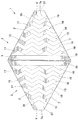
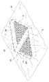
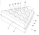
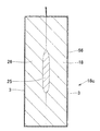
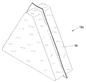
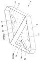
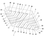
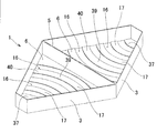
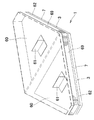
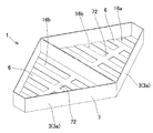
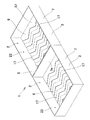
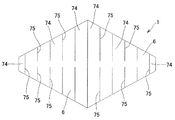
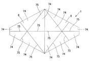
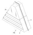
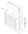
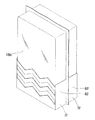
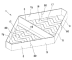
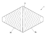
図1〜5において本発明に係るお握り製造用具1は、製造すべきお握りを外側から押圧して締め固めることができる程度の硬度と柔軟性を具えたプラスチックや紙等の素材からなるもので、本実施においては、プラスチック成形によって一体に形成されている。そして、展開状態で見て上端2が解放した同一形状で同一大きさの2個の収容器3,3が、屈曲部5により開閉可能に連結され、且つ、該2個の収容器3,3が展開状態で実質的に線対称を呈する如く構成されている。なお、紙製のお握り製造用具は使い捨て可能であり、プラスチック製のお握り製造用具は繰り返して使用可能である。
In FIGS. 1 to 5, the handgrip manufacturing tool 1 according to the present invention is made of a material such as plastic or paper having hardness and flexibility enough to press and compact a handhold to be manufactured from the outside. In this implementation, they are integrally formed by plastic molding. Then, two containers 3 and 3 having the same shape and the same size with the upper end 2 released when viewed in the unfolded state are connected to each other by the bent portion 5 so as to be openable and closable, and the two containers 3 and 3 are connected. Is configured to exhibit substantially line symmetry in the expanded state. The paper handmade tool is disposable, and the plastic handmade tool can be used repeatedly.
該収容器3は、図1〜4に示すように、本実施例においては平面視で三角形状を呈しており(図3)、三角形板状の基片6の一面側の外周縁の全周囲に亘って、製造すべきお握りの厚さの1/2の高さを有する立壁7が周設されており、三角形の頂部9を形成する立壁部分7aは、三角形の底部10を形成する立壁部分7bと平行しており、全体として、略正三角形状を呈する。そして、該基片6と立壁7との間で、ご飯等の食材を収容するための収容部11が形成されている。又、該左右の収容器3,3の当接状態に向き合う立壁部分7b,7bの縁部12,12相互が、図4〜5に示すように、前記屈曲部5で連結されており、両収容器3,3が閉じた状態で、図6に示すように、該収容器3,3の前記上端(開放端)2,2相互が略合致するように構成されている。
1-4, in this embodiment, the container 3 has a triangular shape in plan view (FIG. 3), and the entire circumference of the outer peripheral edge on one side of the triangular plate-like base piece 6 A standing wall 7 having a height that is ½ of the thickness of the hand grip to be manufactured is provided, and the standing wall portion 7a that forms the triangular top portion 9 is a standing wall portion that forms the triangular bottom portion 10. 7b is substantially equilateral triangular as a whole. And the accommodating part 11 for accommodating foodstuffs, such as rice, is formed between this base piece 6 and the standing wall 7. As shown in FIG. Further, as shown in FIGS. 4 to 5, the edge portions 12 and 12 of the standing wall portions 7 b and 7 b facing the contact state of the left and right containers 3 and 3 are connected by the bent portion 5. In the state where the containers 3 and 3 are closed, as shown in FIG. 6, the upper ends (open ends) 2 and 2 of the containers 3 and 3 are configured to substantially coincide with each other.
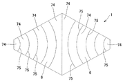
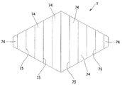
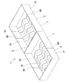
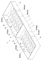
又、前記収容器3の前記基片6には、図1〜3に示すように、対向する傾斜縁13,15間の全長に亘る状態で、三角形の高さ方向に所要間隔を置いて、ジグザグ状に屈曲する開口16が形成され、隣り合う開口16,16間に、撓み変形の容易なジグザグ帯状の押圧片17が形成されている。なお図3においては、説明の便宜上、押圧片17には影線が付されている。
Further, as shown in FIGS. 1 to 3, the base piece 6 of the container 3 has a necessary distance in the height direction of the triangle in a state extending over the entire length between the opposed inclined edges 13 and 15. An opening 16 that is bent in a zigzag shape is formed, and a zigzag belt-shaped pressing piece 17 that is easily deformed is formed between the adjacent openings 16 and 16. In FIG. 3, for convenience of explanation, the pressing piece 17 is shaded.
かかる構成を有するお握り製造用具1の各部の寸法を例示すれば、全体の肉厚が例えば0.4mm程度に設定される共に、収容部3の深さは例えば13mm程度に設定されている。又、三角形の底部10の長さが約90mmに設定されると共に、前記開口16の幅は例えば5mm程度に設定され、該開口16が、三角形の高さ方向に5mm程度の間隔を置いて並設されている。
For example, the dimensions of the respective parts of the hand-grip manufacturing tool 1 having such a configuration are set to a total thickness of, for example, about 0.4 mm, and the depth of the accommodating portion 3 is set to, for example, about 13 mm. Further, the length of the bottom 10 of the triangle is set to about 90 mm, and the width of the opening 16 is set to about 5 mm, for example, and the openings 16 are arranged in parallel at intervals of about 5 mm in the height direction of the triangle. It is installed.
該お握り製造用具1において、前記立壁7は、先端縁19が自由端であるため、撓み変形可能である。又、前記基片6は、前記のようにジグザグ帯状の押圧片17の集合からなるため、撓み変形が容易である。
In the handholding tool 1, the standing wall 7 can be bent and deformed because the distal end edge 19 is a free end. Further, since the base piece 6 is composed of the zigzag belt-like pressing pieces 17 as described above, it is easy to bend and deform.
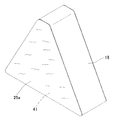
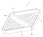
然して、かかる構成を有するお握り製造用具1を用いて、例えば図17に示すような三角形状のお握り18を製造する要領は次のようである。まず図7に示すように、2個の収容器3,3を展開状態にして例えばテーブル面に設置し、その上に、所要大きさのフイルム状物(例えばラップ)21を拡げて被せると共に、図8に示すように、収容器3が形成する収容部11部分において該フイルム状物21を押し込んで収容凹部22,22を形成する。その後、図8〜9に示すように、該収容凹部22,22の底面23,23上に、例えばその全面に亘って所要の具25を載せる。該具25としては、海苔やふりかけ、チーズ、梅干し、魚介類等、従来のお握りで一般的に用いられている各種の具を用いることができる。次に、図9〜10に示すように、前記収容凹部22内にご飯等の食材、例えばご飯26を収容して均す。ご飯26の上面27は、前記立壁7の上縁29から稍盛り上がるようにするのがよい。
However, a procedure for manufacturing a triangular grip 18 as shown in FIG. 17, for example, using the grip manufacturing tool 1 having such a configuration is as follows. First, as shown in FIG. 7, the two containers 3 and 3 are set in an unfolded state, for example, placed on a table surface, and a film-like object (for example, a wrap) 21 having a required size is spread and covered thereon, As shown in FIG. 8, the housing recesses 22 are formed by pushing the film-like material 21 in the housing 11 portion formed by the container 3. Thereafter, as shown in FIGS. 8 to 9, for example, a required tool 25 is placed on the bottom surfaces 23, 23 of the receiving recesses 22, 22 over the entire surface. As the tool 25, various kinds of tools generally used in conventional hand grips such as seaweed, sprinkle, cheese, dried plums, and seafood can be used. Next, as shown in FIGS. 9 to 10, food such as rice, for example, rice 26, is accommodated in the accommodation recess 22 and leveled. The upper surface 27 of the rice 26 is preferably raised from the upper edge 29 of the standing wall 7.
その後、図11〜12に示すように、両収容器3,3を閉じるように、お握り製造用具1を前記屈曲部5で折り曲げる。この折り曲げによって、両収容凹部22,22のご飯の上面27,27が腹合せ状態となる。このように両収容器3,3を折り曲げることによって、両収容器3,3の向き合う立壁7,7が略一連に連なった状態となるが、前記のように、ご飯26の上面27が立壁7の上縁29から稍盛り上がるようになされている関係上、向き合う立壁7,7間は稍開いた状態となる。そしてこの状態で、折り曲げられたご飯が、左右の基片6,6と、底面部30を形成する両立壁部分7b,7bと、一方の側面部31を形成する立壁部分7c,7cと、他方の側面部32を形成する立壁部分7d,7dと、頂面部33を形成する立壁7a,7aが形成するご飯収容体35に拘束状態となる。
Thereafter, as shown in FIGS. 11 to 12, the hand-grip manufacturing tool 1 is bent at the bent portion 5 so as to close both containers 3 and 3. By this bending, the upper surfaces 27 and 27 of the rice in both housing recesses 22 and 22 are in a bellow state. By folding both containers 3 and 3 in this way, the standing walls 7 and 7 facing both containers 3 and 3 are in a substantially continuous state. As described above, the upper surface 27 of the rice 26 is the standing wall 7. Because of the relationship of rising from the upper edge 29, the space between the standing walls 7 and 7 facing each other is in an open state. And in this state, the bent rice has left and right base pieces 6, 6, compatible wall portions 7 b, 7 b forming the bottom surface portion 30, standing wall portions 7 c, 7 c forming one side surface portion 31, and the other The standing wall portions 7d and 7d forming the side surface portion 32 and the standing walls 7a and 7a forming the top surface portion 33 are constrained.
このようにして後、両収容器3,3の基片6,6について、その略全体を内方に押圧する。前記のように、基片6にはジグザグ状の開口16が並設されており、且つ該開口16が、基片6の両傾斜縁13,15間の全長に亘って形成されていることから、開口16,16間の押圧片17及び該開口16で縁36を形成する上端側の押圧片37は、その中央部分39は元より両端側の部分40,40も撓み変形容易である。このようにジグザグ状の押圧片37が形成されていることから、該押圧片37の撓み変形がより大きく確保できるため、形成されるお握りの両側面41,41(図11、図13)をより深く効果的に押圧できる。これにより、お握りをより効果的に締め固めることができると共に、前記具25をお握りの両側面41,41により確実に付着させることができる。
After that, substantially the whole of the base pieces 6 and 6 of both containers 3 and 3 is pressed inward. As described above, the base piece 6 is provided with the zigzag-shaped openings 16 side by side, and the openings 16 are formed over the entire length between the inclined edges 13 and 15 of the base piece 6. In the pressing piece 17 between the openings 16 and 16 and the pressing piece 37 on the upper end side forming the edge 36 by the opening 16, the central portion 39 and the portions 40 and 40 on both end sides are also easily bent and deformed. Since the zigzag-shaped pressing piece 37 is formed in this way, the bending deformation of the pressing piece 37 can be ensured more greatly, so that both side surfaces 41 and 41 (FIGS. 11 and 13) of the formed grip are more It can be pressed deeply and effectively. As a result, the hand grip can be more effectively compacted, and the tool 25 can be reliably attached to the both side surfaces 41, 41 of the hand grip.
このように締め固める際、収容器3の前記立壁7も内方に押圧することにより、該立壁7の撓み変形によってお握りの周面42をも効果的に締め固めることができ、図13に示すように、全体として所要に締め固められたお握り18を製造できる。
When compacting in this way, the peripheral wall 42 of the grip can be effectively compacted by the bending deformation of the standing wall 7 by also pressing the standing wall 7 of the container 3 inward, as shown in FIG. As described above, the grip 18 that is compacted as necessary can be manufactured as a whole.
このようなお握りの締め固めは、従来のお握りを作る要領で行うことができる。例えば図14に示すように、両収容器3,3を折り曲げた後に、一方の手43は、その掌の中央部分を、折り曲げ状態にあるお握り製造用具1の前記底面部30に当て、その親指46を一方の基片6aに当てると共に残り4本の指を他方の基片6bに当て、且つ、他方の手49の掌の中央部分を、折り曲げ状態にあるお握り製造用具の前記頂面部33に当て、該手49の指51を前記一方の側面部31に当てると共に他方の側面部32を掌の内側部分に当て、両基片6a,6bや両立壁7,7を周方向から押圧するようにご飯を締め固める。これにより、手を汚すことなく、各部が略均等に締め固められて全体が一体化したお握りを能率良く容易にしかも衛生的に製造できることとなる。
Such a grip compaction can be performed in the manner of making a conventional grip. For example, as shown in FIG. 14, after folding both containers 3 and 3, one hand 43 puts the central portion of its palm against the bottom portion 30 of the hand-grip manufacturing tool 1 in the folded state, and its thumb. 46 is applied to one base piece 6a, the remaining four fingers are applied to the other base piece 6b, and the central part of the palm of the other hand 49 is placed on the top surface portion 33 of the hand grip manufacturing tool in a bent state. Put the finger 51 of the hand 49 against the one side part 31 and the other side part 32 against the inner part of the palm so as to press both the base pieces 6a, 6b and the compatibility walls 7, 7 from the circumferential direction. The rice is compacted. As a result, it is possible to efficiently and easily manufacture a handgrip in which the respective parts are compacted substantially uniformly and the whole is integrated without making the hands dirty.
なお、このように締め固める際、両収容器3,3が断熱性を有するため、炊きたて等の熱いご飯を締め固めるときも、その熱さをそれほど感じずに締め固めることができる。
In addition, since both containers 3 and 3 have heat insulation when compacting in this way, even when hot rice such as freshly cooked food is compacted, the heat can be compacted without feeling so much.
このように各部を締め固めることにより、フイルム状物21を介してお握り製造用具1で包装された図13、図15に示す包装お握り18aが得られ、製造されたお握り18を、その型崩れを防止しながら衛生的に持ち運ぶことができる。そして、前記フイルム状物21が保湿効果を発揮するため、製造後一定時間を経過した後も、お握りを美味しく食べることができる。
By compacting each part in this way, the packaging grip 18a shown in FIGS. 13 and 15 packed with the grip manufacturing tool 1 through the film-like material 21 is obtained, and the manufactured grip 18 is deformed. It can be carried hygienically while preventing. And since the said film-like thing 21 exhibits a moisturizing effect, even after a lapse of a certain time after manufacture, the nigiri can be eaten deliciously.
なお、製造した包装お握り18aは、体裁上、図15に示すように、お握り18の周面42に沿うようにフイルム状物21の縁部分55を短くカットするのがよい。このように得られた包装お握り18aにあっては、お握りの側面41に配置された具25が前記開口16及びフイルム状物21を通して見えるため、具の種類を容易に判別できる。
In addition, as shown in FIG. 15, the manufactured packaging handgrip 18a is good to cut the edge part 55 of the film-like thing 21 short so that the surrounding surface 42 of the handgrip 18 may be met. In the packaging handgrip 18a obtained in this way, the tool 25 arranged on the side face 41 of the handgrip can be seen through the opening 16 and the film-like object 21, so that the kind of the tool can be easily discriminated.
そして、お握りを食べる際は、例えば図16に示すように、一方の収容器3aを水平状態にして他方の収容器3bを開くことにより、フイルム状物21で被覆されたお握り18bを取り出す。取り出されたお握り18bを図17に示す。その後、フイルム状物21を剥がすことによってお握りを食べるのであるが、この際、フイルム状物21を先側から剥がしながら、お握りの側面41をフイルム状物21を介して持って食べることができるため、指を汚すことなく然も衛生的に食べることができる。
And when eating a nigiri, as shown in FIG. 16, for example, the handle 18b covered with the film-like material 21 is taken out by opening one container 3a in a horizontal state and opening the other container 3b. The extracted hand grip 18b is shown in FIG. After that, the handgrip is eaten by peeling off the film-like material 21. At this time, the side-face 41 of the handgrip can be held through the film-like material 21 while being peeled off from the front side. You can eat hygienically without getting your fingers dirty.
そして、お握りが取り出されたお握り製造用具1は、別のお握りを製造するために再使用できる。
And the hand-grip manufacturing tool 1 from which the hand-grip was taken out can be reused in order to manufacture another hand-grip.
図18は、前記構成を有するお握り製造用具1の他の使用態様を示すものであり、前記したフイルム状物21に代えて所要大きさの板状海苔56を用い、展開状態にある2個の収容器3,3上の全体に所要大きさの板状海苔56を被せると共に、該収容器3,3が形成する収容部11,11部分において該板状海苔56を押し込んで収容凹部22,22を形成する。その後図19に示すように、形成した収容凹部22にご飯26を収容する。なお図19においては、収容器3に収容されたご飯の上面27に具25が配置されている。その後、前記と同様に、両収容器3,3を前記屈曲部5で折り曲げて後、前記と同様の工程を経てお握りを締め固めることにより、図20〜21に示すような、板状海苔56で包まれ且つ内部に具が配置されたお握り18cを製造できる。
FIG. 18 shows another usage mode of the hand-grip manufacturing tool 1 having the above-described configuration. The plate-shaped laver 56 having a required size is used in place of the above-described film-like material 21, and two unfolded pieces are in a developed state. A plate-shaped laver 56 having a required size is placed on the entire container 3, 3, and the plate-like seaweed 56 is pushed into the container 11, 11 formed by the container 3, 3, thereby accommodating the recess 22, 22. Form. Then, as shown in FIG. 19, the rice 26 is accommodated in the formed accommodation recess 22. In addition, in FIG. 19, the tool 25 is arrange | positioned on the upper surface 27 of the rice accommodated in the container 3. As shown in FIG. Thereafter, as described above, both the containers 3 and 3 are bent at the bent portion 5, and then the grip is tightened through the same process as described above, whereby a plate-like seaweed 56 as shown in FIGS. A hand grip 18c that is wrapped in and has a tool disposed therein can be manufactured.
本発明に係るお握り製造用具1は、前記のようにフイルム状物21を用いて使用されることの他、フイルム状物を用いないで使用されることもある。図22は、各収容器3,3の収容部11,11の底面59,59に、例えば三角形状に切断された板状海苔や板状チーズ等の板状の具25aを載せて前記各開口16を塞いだ状態とし、然る後、図23に示すように、このように開口16を塞いで形成した収容凹部22,22(図22)にご飯26を収容すると共に、一方の収容器のご飯上面27に具25bを配置した場合を示すものである。図24に示すように、ご飯が収容された両収容器3,3を閉じるように前記屈曲部5で折り曲げ、製造されるお握りの両側面41,41を、前記具25aを介して押圧することにより、図24〜25に示すような、両側面41,41に具25a,25aが付着され且つ内部に具25bが配置されたお握り18を製造できる。
The handgrip manufacturing tool 1 according to the present invention may be used without using a film-like material in addition to being used with the film-like material 21 as described above. FIG. 22 shows that each of the openings is formed by placing a plate-like tool 25a such as plate-like seaweed or plate-like cheese cut into a triangular shape on the bottom surfaces 59, 59 of the container parts 11, 11 of the containers 3, 3. 16, and then, as shown in FIG. 23, the rice 26 is accommodated in the accommodating recesses 22 and 22 (FIG. 22) formed by closing the opening 16 as described above, and one of the containers is The case where the tool 25b is arrange | positioned on the rice upper surface 27 is shown. As shown in FIG. 24, both side surfaces 41 and 41 of the handle manufactured by bending at the bent portion 5 so as to close both containers 3 and 3 in which rice is stored are pressed through the tool 25a. Thus, as shown in FIGS. 24 to 25, the handle 18 can be manufactured in which the tools 25 a and 25 a are attached to the side surfaces 41 and 41 and the tool 25 b is arranged inside.
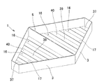
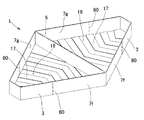
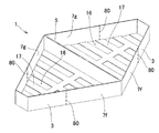
図26〜27、図28〜29、図30〜31は、本発明に係るお握り製造用具1の他の実施例を示すものであり、収容器3を構成する基片6に設ける開口16の構成が実施例1における場合と相違し、その他の構成は前記と同様である。
FIGS. 26 to 27, FIGS. 28 to 29, and FIGS. 30 to 31 show another embodiment of the grip manufacturing tool 1 according to the present invention, and the configuration of the opening 16 provided in the base piece 6 constituting the container 3. Is different from that in the first embodiment, and the other configurations are the same as described above.
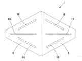
図26〜27においては、対向する傾斜縁13,15間の全長に亘る状態で、基片6の三角形の高さ方向に所要間隔を置いて、例えば5mm程度の間隔を置いて、緩いV字状に屈曲する開口16が形成されている。
In FIGS. 26 to 27, in a state extending over the entire length between the inclined edges 13 and 15 facing each other, a required interval is provided in the height direction of the triangle of the base piece 6, for example, an interval of about 5 mm, and a loose V-shape. An opening 16 that is bent in a shape is formed.
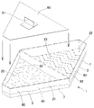
又図28〜29に示すお握り製造用具1にあっては、対向する傾斜縁13,15間の全長に亘る状態で、緩い円弧状をなす開口16が形成されている。
In addition, in the grip manufacturing tool 1 shown in FIGS. 28 to 29, a loose arc-shaped opening 16 is formed over the entire length between the opposing inclined edges 13 and 15.
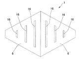
又図30〜31に示すお握り製造用具1にあっては、対向する傾斜縁13,15間の全長に亘る状態で、直線状の開口16が形成されている。
30 to 31 has a linear opening 16 formed over the entire length between the inclined edges 13 and 15 facing each other.
上記の各お握り製造用具1にあっては、何れも、対向する傾斜縁13,15間の全長に亘る状態で開口16が設けられているため、前記と同様、隣り合う開口16,16間に形成された押圧片17、及び該開口16で縁59を形成する上端側の押圧片37は、その中央部分39は元より両端側の部分40,40も撓み変形できると共に、形成されるお握りの両側面41,41を略均等に押圧でき、これにより、お握りを締め固めることができる。その際、収容器3の立壁7においても、これを内方に押圧することにより、お握りの周面をも締め固めることができ、全体として所要に締め固められたお握りを製造でき、又、開口16を通して具の種類を判別できる。
In each of the hand grip manufacturing tools 1 described above, since the opening 16 is provided in a state extending over the entire length between the opposed inclined edges 13 and 15, as in the above, between the adjacent openings 16 and 16. The formed pressing piece 17 and the pressing piece 37 on the upper end side forming the edge 59 by the opening 16 can be bent and deformed at the center portion 39 as well as the portions 40 and 40 at both end sides. The both side surfaces 41, 41 can be pressed substantially evenly, whereby the grip can be tightened. At that time, even on the standing wall 7 of the container 3, by pressing this inward, the peripheral surface of the grip can be compacted as a whole, and a hand-compressed grip can be produced as a whole. The type of the tool can be determined through 16.
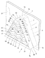
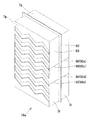
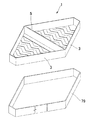
図32〜36は、前記構成を有するお握り製造用具1の販売形態の一例を示すものであり、展開状態にある2個の収容器3,3上に、所要大きさのフイルム状物21を拡げて被せると共に、収容器3が形成する収容部11において該フイルム状物21を押し込んで収容凹部22を形成する。その後、該収容凹部22の底面23,23に所要の具25を載せると共に、図33に示すように、載せた具25上に、収容凹部22の底面形状に略合致した蓋片60を被せる。これにより、前記具25が固定された状態となる。なお、該蓋片60には図32に示すように摘まみ片61を設けておくのがよい。又前記フイルム状物21の周縁部分62は、前記収容器3の立壁7の外面63に重なる如くなし、該重ね代65の一部分又は全体を、剥離性糊を用いて該外面63に固定する。前記周縁部分62を前記立壁7の外面63に固定する手段としては、図34に示すように、該フイルム状物21の縁部分62を、シール片67を用いて外面63に分離可能に固定してもよい。或いは、図35に示すように、立壁7の外周全体を取り囲むように紙製等の帯状片69で前記周縁部分62を環状に挾持することにより行ってもよい。かかる帯状片69は、その一部を切断すれば、フイルム状物21の周縁部分62を立壁7と分離させることができる。
FIGS. 32 to 36 show an example of a sales form of the hand-grip manufacturing tool 1 having the above-described configuration. A film-like object 21 having a required size is spread on two containers 3 and 3 in an unfolded state. The film recess 21 is formed by pushing the film-like material 21 into the accommodating portion 11 formed by the container 3. Thereafter, the required tool 25 is placed on the bottom surfaces 23 and 23 of the housing recess 22, and a lid piece 60 that substantially matches the bottom shape of the housing recess 22 is placed on the placed tool 25 as shown in FIG. 33. Thereby, the tool 25 is in a fixed state. The lid piece 60 is preferably provided with a knob 61 as shown in FIG. Further, the peripheral portion 62 of the film-like material 21 is formed so as to overlap the outer surface 63 of the standing wall 7 of the container 3, and a part or the whole of the overlap margin 65 is fixed to the outer surface 63 using a peelable glue. As means for fixing the peripheral portion 62 to the outer surface 63 of the standing wall 7, as shown in FIG. 34, the edge portion 62 of the film-like object 21 is detachably fixed to the outer surface 63 using a seal piece 67. May be. Alternatively, as shown in FIG. 35, the peripheral portion 62 may be annularly held by a strip-like piece 69 made of paper or the like so as to surround the entire outer periphery of the standing wall 7. If the strip-like piece 69 is partially cut, the peripheral edge portion 62 of the film-like object 21 can be separated from the standing wall 7.
このようにして後、具25を具えた展開状態のお握り製造用具1の全体を図36に示すように包装袋70に納めて後、上端開放の内箱71内にその複数個、例えば2個を収容し、且つこれを外箱68に納めて販売できる。なお該内箱71の大きさは、例えば図37に示すように、2個のお握り製造用具1を用いて製造された三角形状の包装お握り18aの2個を収納できる大きさに設定する。
In this way, after the entire grip manufacturing tool 1 including the tool 25 is placed in the packaging bag 70 as shown in FIG. 36, a plurality of, for example, two of them are placed in the inner box 71 open at the upper end. Can be stored in the outer box 68 and sold. For example, as shown in FIG. 37, the size of the inner box 71 is set to a size that can accommodate two of the triangular packaging grips 18a manufactured using the two grip manufacturing tools 1.
このように構成した場合は、購入者は次のようにしてお握りを製造できる。即ち、前記お握り製造用具1を包装紙70から取り出した後に前記蓋片60を除去し、各収容凹部22にご飯を収容する。その後、両収容器3,3を閉じるように前記屈曲部5で折り曲げ、収容状態にあるご飯を両収容器3,3の外側から締め固める。これにより、両収容器3,3にフイルム状物を被せたり、収容凹部22に具を載せる等の手間を要することなく、手軽にお握りを製造できることとなる。お握りを製造した後、前記周縁部分62を前記立壁7の外面63から分離する。このようにして製造されたお握りを前記包装箱71に収納することにより、該包装箱71を、製造されたお握りを持ち運ぶ弁当箱として再利用できる。
When configured in this way, the purchaser can manufacture the grip as follows. That is, after the hand-grip manufacturing tool 1 is taken out from the wrapping paper 70, the lid piece 60 is removed, and rice is stored in each storage recess 22. Thereafter, the containers 3 and 3 are folded at the bent portion 5 so as to be closed, and the rice in the accommodated state is compacted from the outside of the containers 3 and 3. Thus, the grip can be easily manufactured without the need for covering the containers 3 and 3 with a film-like material or placing a tool on the receiving recess 22. After manufacturing the hand grip, the peripheral portion 62 is separated from the outer surface 63 of the standing wall 7. By storing the manufactured handgrip in the packaging box 71, the packaging box 71 can be reused as a lunch box for carrying the manufactured handgrip.
図38〜39は、本発明に係るお握り製造用具1のその他の態様を示すものであり、基片6に直線状の開口16が並設された図30〜31のお握り製造用具1において、先端の開口16aを除く各開口16bが、長さ方向の中央部分で繋ぎ片72により分断された構成を有している。
38 to 39 show another embodiment of the hand grip manufacturing tool 1 according to the present invention. In the hand grip manufacturing tool 1 of FIG. 30 to FIG. Each opening 16b except for the opening 16a has a configuration in which it is divided by a connecting piece 72 at a central portion in the length direction.
このように分断状態とする場合、一方の収容器3aについてのみ分断状態とし、他方の収容器3bについては開口16が連続するように構成されることもある。かかる構成のお握り製造用具1によるときも、隣り合う開口16,16間に形成された押圧片17と該開口16で縁36を形成する押圧片37、及び前記立壁7の夫々の撓み変形性によって、全体として所要に締め固められたお握りを製造できる。又、開口16を通して具の種類を判別できる。
In this way, when the divided state is set, only the one container 3a may be divided and the other container 3b may be configured such that the opening 16 is continuous. Even with the grip manufacturing tool 1 having such a configuration, the pressing piece 17 formed between the adjacent openings 16 and 16, the pressing piece 37 forming the edge 36 by the opening 16, and the bending deformability of the standing wall 7. As a whole, you can produce handfuls that are compacted as required. Further, the type of the tool can be discriminated through the opening 16.
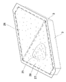
又図40〜41は、本発明に係るお握り製造用具1のその他の態様を示すものであり、前記両基片6,6の中央部分に、例えば台形状や円形状等の比較的大きな開口16,16を設けた場合を示すものである。なお、お握り製造用具1の意匠性を考慮して、2個の収容器3,3の基片6,6に設ける開口16の形態を異ならせることもある。かかる構成のお握り製造用具1によるときは、該開口16,16において、形成されるお握りの両側面を押圧できると共に、該開口16,16の周縁部分73,73において基片6が撓み変形可能であることと、前記立壁7の撓み変形性によって、全体として所要に締め固められたお握りを製造できる。又、開口16を通して具の種類を判別できる。
40 to 41 show other aspects of the hand grip manufacturing tool 1 according to the present invention, and a relatively large opening 16 such as a trapezoidal shape or a circular shape is formed in the central portion of the base pieces 6 and 6. , 16 are shown. The form of the opening 16 provided in the base pieces 6 and 6 of the two containers 3 and 3 may be made different in consideration of the design of the grip manufacturing tool 1. When the grip manufacturing tool 1 having such a configuration is used, both sides of the formed grip can be pressed at the openings 16 and 16, and the base piece 6 can be bent and deformed at the peripheral portions 73 and 73 of the openings 16 and 16. Due to the fact that the standing wall 7 is bent and deformable, a grip that is compacted as a whole can be manufactured. Further, the type of the tool can be discriminated through the opening 16.
このように基片6の中央部分に大きな開口16を設ける場合は、該開口16部分において、製造すべきお握りの側面を押圧できるため、該基片6が撓み変形できないものであることもある。
Thus, when providing the large opening 16 in the center part of the base piece 6, since the side surface of the handle which should be manufactured can be pressed in this opening 16 part, this base piece 6 may be a thing which cannot bend and deform | transform.
図42〜43は、本発明に係るお握り製造用具1のその他の実施例を裏面形態で示すものであり、開口16の形態が前記と異なる。
FIGS. 42-43 shows the other Example of the hand-grip manufacturing tool 1 which concerns on this invention with a back surface form, and the form of the opening 16 differs from the above.
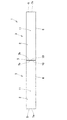
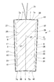
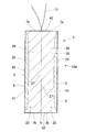
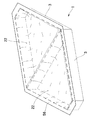
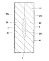
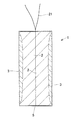
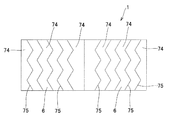
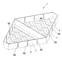
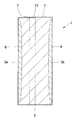
図44〜45は、本発明に係るお握り製造用具1のその他の実施例を示すものであり、屈曲部5で連結された2個の収容器3,3が、平面視で四角形状を呈する如くなされ、四角形状の基片6の一面側の外周縁に、製造すべきお握りの厚さの略1/2の高さを有する立壁7が周設されており、該基片6と立壁7との間で、ご飯等を収容するための収容凹部22が形成されている。そして両収容器3,3の、底部を形成する当接状態の立壁部分7e,7eの縁部(長辺の縁部でもよいが、本実施例においては短辺の縁部)相互が前記屈曲部5で連結されている。そして、両収容器3,3が閉じた状態で、図46に示すように、該収容器3,3の上端(開放端)2,2相互が略合致するように構成されている。
44 to 45 show another embodiment of the hand grip manufacturing tool 1 according to the present invention, in which the two containers 3 and 3 connected by the bent portion 5 have a quadrangular shape in plan view. A standing wall 7 having a height approximately half the thickness of the handle to be manufactured is provided around the outer peripheral edge of one side of the rectangular base piece 6, and the base piece 6, An accommodation recess 22 for accommodating rice or the like is formed therebetween. Then, the edges of the standing wall portions 7e and 7e forming the bottom of the containers 3 and 3 (the edge of the long side may be the edge of the long side, but the edge of the short side in this embodiment) are bent. They are connected by part 5. Then, with both containers 3 and 3 closed, as shown in FIG. 46, the upper ends (open ends) 2 and 2 of the containers 3 and 3 are configured to substantially match each other.
又収容器3の前記基片6には、平行状態に対向する縁77,79の全長に亘る状態で、該縁の長さ方向に所要間隔を置いて、例えばジグザグ状に屈曲する開口16が形成されている。該開口16は、例えば5mm程度の幅に設定されると共に、前記縁77,79の長さ方向に5mm程度の間隔を置いて並設されている。
In addition, the base piece 6 of the container 3 has an opening 16 that bends in a zigzag manner, for example, at a required interval in the length direction of the edges 77 and 79 across the entire length of the edges 77 and 79 facing in parallel. Is formed. The opening 16 is set to have a width of about 5 mm, for example, and is arranged in parallel with a distance of about 5 mm in the length direction of the edges 77 and 79.
かかる構成を有するお握り製造用具1を用いて、例えば図47に示すような四角形状のお握り18dを製造する要領は前記と同様であり、図48に示すように、フイルム状物21を介して形成された収容凹部22,22にご飯26を収容して後、図49に示すように、左右の収容器33を閉じるように前記屈曲部5で折り曲げることにより、隣り合う開口16,16間に形成された押圧片17と該開口16で縁36を形成する押圧片37、前記立壁7の撓み変形性によって、全体として所要に締め固められた包装お握り18aを製造できる。又、開口16を通して具の種類を判別できる。
For example, the procedure for manufacturing a square-shaped grip 18d as shown in FIG. 47 using the grip manufacturing tool 1 having such a configuration is the same as described above, and is formed via a film-like object 21 as shown in FIG. 49. After the rice 26 is accommodated in the accommodated recesses 22 and 22, as shown in FIG. 49, it is formed between the adjacent openings 16 and 16 by bending the bent portion 5 so as to close the left and right containers 33. Due to the pressed piece 17 and the pressed piece 37 forming the edge 36 by the opening 16 and the bending deformability of the standing wall 7, the package grip 18 a that is compacted as a whole can be manufactured. Further, the type of the tool can be discriminated through the opening 16.
図50〜56は、本発明に係るお握り製造用具1のその他の実施例を裏面形態で示すものであり、前記のように開口16を設ける代わりに基片6に切り目75を設けた構成を有している。このように構成する場合も、該切り目75で縁を形成する押圧片74及び前記立壁7の撓み変形性によって、全体として所要に締め固められたお握りを製造できる。
50 to 56 show another embodiment of the handgrip manufacturing tool 1 according to the present invention in the form of a back surface, and has a configuration in which a cut 75 is provided in the base piece 6 instead of providing the opening 16 as described above. doing. Even when configured in this way, a grip that has been compacted as a whole can be manufactured by the pressing piece 74 forming an edge by the cut line 75 and the bending deformability of the standing wall 7.
図57、図62〜63、図70、図72〜73、図75〜78は、製造されたお握りの食べやすさに配慮されたお握り製造用具1の一例を示すものである。かかる構成は、これまでの実施例では個別に説明していないが、本発明が包含する全ての実施例について共通するので、ここで纏めてその構成とその使用例を説明する。
57, 62-63, 70, 72-73, and 75-78 show an example of the hand-grip manufacturing tool 1 in consideration of the ease of eating of the hand-made hand. Although such a configuration has not been individually described in the embodiments so far, it is common to all the embodiments included in the present invention, and therefore the configuration and an example of use thereof will be described here.
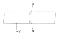
図57は、直線状の開口16が設けられた図30〜31に示すお握り製造用具1に関連するものであって、平面視で三角形状を呈する収容器3,3の夫々の対向する辺をなす立壁部分7f,7g、7f,7gに、収容器3,3相互を連結する屈曲部5から略等距離にある部位においてミシン目状の切り取り線80が設けられている。図57では該切り取り線80を、開口16,16間の押圧片17が存する部分と、開口16が存する部分に設けている。該切り取り線80は、押圧片17が存する部分のみに、或いは開口16が存する部分のみに設けてもよい。
FIG. 57 relates to the grip manufacturing tool 1 shown in FIGS. 30 to 31 provided with a linear opening 16, and shows the opposing sides of the containers 3 and 3 that are triangular in plan view. The standing wall portions 7f, 7g, 7f, and 7g are provided with perforated cut lines 80 at portions that are substantially equidistant from the bent portion 5 that connects the containers 3 and 3 to each other. In FIG. 57, the cut lines 80 are provided in a portion where the pressing piece 17 between the openings 16 and 16 exists and a portion where the opening 16 exists. The cut line 80 may be provided only in a portion where the pressing piece 17 exists or only in a portion where the opening 16 exists.
該切り取り線80が、押圧片17が存する部分に設けられた場合は、フイルム状物21を介在させ、実施例1で説明したと同様の工程を経ることによって図58に示す包装お握り18aを製造した後、前記立壁部分7f,7gを、前記押圧片17が存する部分の切り取り線80で切断すると、対向する切り取り線80a,80a、80a,80aの上側(先側)に存する三角形状の収容器上側部分81,81を、図59に示すように、前記押圧片17で外側に折り曲げることができる。この折り曲げた状態で、前記フイルム状物21の先側部分を剥がすと、図60に示すように、お握り18の上側部分(先側の部分)81を露出させることができる。この状態で、前記切り取り線80a,80a、80a,80aよりも下側に存する収容器下側部分82,82を手で持って安定した状態でお握りの上側部分を食べることができる。お握りの上側部分を食べた後は、該左右の収容器下側部分82,82を開いて、フイルム状物21で被覆されたお握りの下側部分を取り出し、食べることができる。このとき、お握りの上側部分だけを食べて下側部分を残すばあいは、前記屈曲した収容器上側部分81,81を元に戻すことにより、お握りを再び包装状態となし得る。
When the cut line 80 is provided in the portion where the pressing piece 17 exists, the film grip 21a shown in FIG. 58 is manufactured through the same process as described in the first embodiment with the film 21 interposed therebetween. After that, when the standing wall portions 7f and 7g are cut at the cut line 80 where the pressing piece 17 exists, the triangular container located above (front side) the opposite cut lines 80a, 80a, 80a and 80a. As shown in FIG. 59, the upper portions 81 and 81 can be bent outward by the pressing piece 17. When the front side portion of the film-like object 21 is peeled in this folded state, as shown in FIG. 60, the upper side portion (front side portion) 81 of the grip 18 can be exposed. In this state, the upper part of the handgrip can be eaten in a stable state by holding the container lower parts 82, 82 existing below the cut lines 80a, 80a, 80a, 80a by hand. After eating the upper part of the handgrip, the lower parts 82, 82 of the left and right containers are opened, and the lower part of the handgrip covered with the film-like material 21 can be taken out and eaten. At this time, if only the upper part of the handgrip is eaten and the lower part is left, the handgrip can be put into a packaged state again by returning the bent container upper parts 81, 81 to the original state.
又、前記立壁部分7f,7gを、前記開口16が存する部分の切り取り線80bで切断すると、該開口16が、基片6の対向する縁13,15間の全長に亘る状態で設けられているため、対向する切り取り線80b,80b、80b,80bの上側(先側)に存する収容器上側部分81,81を、図61に示すように取り除くことができる。このようにした後、前記フイルム状物21の先側部分を剥がすと、図60に示すと同様にして、お握り18の上側部分を露出させることができる。
Further, when the standing wall portions 7f and 7g are cut by a cut line 80b where the opening 16 exists, the opening 16 is provided in a state extending over the entire length between the opposing edges 13 and 15 of the base piece 6. Therefore, the container upper portions 81, 81 existing on the upper side (front side) of the opposing cut lines 80 b, 80 b, 80 b, 80 b can be removed as shown in FIG. 61. After this, when the front side portion of the film-like object 21 is peeled off, the upper side portion of the hand grip 18 can be exposed in the same manner as shown in FIG.
なお図57に示すように、前記押圧片17に、対向する切り取り線80a,80a相互を連結するようにミシン目状の折り曲げ線82を設けておくと、図59に示す押圧片17での折り曲げを容易に行うことができて好ましい。なお、該折り曲げ線82で押圧片17を切断することもできる。
As shown in FIG. 57, if the pressing piece 17 is provided with a perforated folding line 82 so as to connect the opposing cut lines 80a, 80a, the bending at the pressing piece 17 shown in FIG. Can be easily performed. Note that the pressing piece 17 can also be cut by the fold line 82.
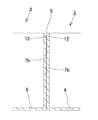
図62〜63は、左右の収容器3,3が矩形状をなす図44に示すお握り製造用具1に関連するものであり、収容器3,3の夫々の対向する辺をなす立壁部分7f,7g、7f,7gに、収容器3,3相互を連結する屈曲部5から略等距離にある部位においてミシン目状の切り取り線80が設けられている。なお図63に示すお握り製造用具1は、前記収容器3,3が稍縦長に形成されている。
FIGS. 62 to 63 relate to the handle manufacturing tool 1 shown in FIG. 44 in which the left and right containers 3, 3 are rectangular, and the standing wall portions 7 f that form the opposing sides of the containers 3, 3. 7g, 7f, and 7g are provided with perforated cut lines 80 at portions that are substantially equidistant from the bent portion 5 that connects the containers 3 and 3 to each other. Note that the container manufacturing tool 1 shown in FIG.
図63に示すお握り製造用具1にあっては、縦長のお握りを食べやすくするために、その長さ方向の両側に位置させて切り取り線80,80、80,80が設けられている。該切り取り線80は、前記と同様に、押圧片17が存する部分に設けられてもよいのであるが、本実施例においては開口16が存する部分に設けられている。
In the hand-grip manufacturing tool 1 shown in FIG. 63, cut lines 80, 80, 80, 80 are provided on both sides in the length direction in order to make it easier to eat a vertically long hand-grip. The cut line 80 may be provided in a portion where the pressing piece 17 exists, as described above, but in the present embodiment, it is provided in a portion where the opening 16 exists.
図64は、前記縦長のお握り製造用具1を用いて製造された包装お握り18aを示すものであり、前記立壁部分7f,7g、7f,7gを、上側の切り取り線80c,80c、80c,80cで切断することにより、図65に示すように、収容器上側部分83,83(図64)を取り除くことができる。更に、前記立壁部分7f,7g、7f,7gを、下側の切り取り線80d,80d、80d,80dで切断することにより、図66に示すように、収容器中間部分85,85(図65)を取り除くことができる。このようにして後、フイルム状物21を上から順次剥がして、収容器下側部分82,82を手で持ってお握りを安定状態で食べることができる。
FIG. 64 shows a package hand grip 18a manufactured using the vertical hand grip manufacturing tool 1, and the standing wall portions 7f, 7g, 7f, 7g are separated by upper cut lines 80c, 80c, 80c, 80c. By cutting, the container upper portions 83 and 83 (FIG. 64) can be removed as shown in FIG. Further, by cutting the standing wall portions 7f, 7g, 7f, 7g with the lower cut lines 80d, 80d, 80d, 80d, as shown in FIG. 66, the container intermediate portions 85, 85 (FIG. 65). Can be removed. After that, the film-like object 21 can be peeled off sequentially from above, and the grip can be eaten in a stable state while holding the container lower portions 82 and 82 by hand.
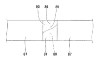
なお、立壁部分7f,7gに切り取り線80を設ける前記各収容器3において、該切り取り線80は、図67に示すように、立壁部分の幅方向の両端部分86,86を残して中間部分に連続状態に設けられることもある。又図68に示すように、立壁部分7f,7gの幅方向の端部側にのみ切り取り線80が設けられることもある。或いは図69に示すように、幅方向で切り離された立壁部分87,87の切断部89,89を突き合わせ、且つ、突き合わせ部分90の外面側を剥離性の粘着テープ91で覆うことによって切り取り線80を構成することもある。
In each of the containers 3 in which the cut wall 80 is provided in the standing wall portions 7f and 7g, the cut line 80 is provided in the middle portion with both end portions 86 and 86 in the width direction of the standing wall portion as shown in FIG. It may be provided in a continuous state. Further, as shown in FIG. 68, a cut line 80 may be provided only on the end side in the width direction of the standing wall portions 7f and 7g. Alternatively, as shown in FIG. 69, the cutting portions 89 and 89 of the standing wall portions 87 and 87 separated in the width direction are abutted, and the outer surface side of the abutting portion 90 is covered with a peelable adhesive tape 91, thereby forming a cut line 80. May be configured.
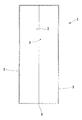
図70は本発明に係るお握り製造用具1の他の実施例を示すものであって、収容器3を構成する基片6に前記開口16や前記切り目75が設けられていない場合において、収容器3,3の夫々の対向する辺をなす立壁部分7f,7g、7f,7gに、収容器3,3相互を連結する屈曲部5から略等距離にある部位においてミシン目状の切り取り線80を設けた場合を示すものである。この場合は、前記と同様にして、包装お握り18aを製造した後、全ての切り取り線80で立壁部分を切断すると、対向する切り取り線80,80、80,80の上側(先側)に存する三角形状の収容器上側部分81,81を、図71に示すように、前記基片6で折り曲げることができる。なおこの場合、図72に示すように、前記基片6に、対向する切り取り線80,80相互を連結するようにミシン目状の折り曲げ線82を設けておくと、基片6での折り曲げを容易に行うことができて好ましい。なお該折り曲げ線82で基片6を切断することもできる。切断した場合は、前記収容器上側部分81,81を取り除くことができる。
FIG. 70 shows another embodiment of the handgrip manufacturing tool 1 according to the present invention. In the case where the opening 16 and the cut 75 are not provided in the base piece 6 constituting the container 3, the container A perforated cut line 80 is provided on each of the standing wall portions 7f, 7g, 7f, 7g forming the opposite sides of 3 and 3 at a portion approximately equidistant from the bent portion 5 connecting the containers 3 and 3 to each other. It shows the case where it is provided. In this case, after manufacturing the packaging handgrip 18a in the same manner as described above, when the standing wall portion is cut by all the cut lines 80, the triangles existing on the upper side (front side) of the opposed cut lines 80, 80, 80, 80. The container upper portions 81 and 81 having a shape can be bent by the base piece 6 as shown in FIG. In this case, as shown in FIG. 72, if the base piece 6 is provided with a perforated folding line 82 so as to connect the opposing cut lines 80, 80, the base piece 6 is bent. It can be easily performed and is preferable. The base piece 6 can also be cut along the fold line 82. When cut, the container upper portions 81 and 81 can be removed.
又図72、図73は、本発明に係るお握り製造用具1のその他の実施例を示すもので、対向する縁13,13間の全長に亘る状態では開口16が設けられておらず、収容器3,3の夫々の対向する辺をなす立壁部分7f,7g、7f,7gに、収容器3,3相互を連結する屈曲部5から略等距離にある部位においてミシン目状の切り取り線80が設けられている。そして図72に示すように、基片6に、対向する立壁部分に設けられた切り取り線80,80間を繋ぐように折り曲げ線82が設けられている。或いは図73に示すように、対向する立壁部分に設けられた切り取り線80,80間を繋ぐように、且つ隣り合う開口16,16間を繋ぐように折り曲げ線82が設けられている。なお該折り曲げ線82で基片6を切断することもできる。切断した場合は、前記収容器上側部分81,81を取り除くことができる。
72 and 73 show another embodiment of the grip manufacturing tool 1 according to the present invention. In the state extending over the entire length between the opposite edges 13, 13, the opening 16 is not provided, and the container A perforated cut line 80 is formed on each of the standing wall portions 7f, 7g, 7f, 7g forming the opposite sides 3 and 3 at a portion approximately equidistant from the bent portion 5 connecting the containers 3 and 3 to each other. Is provided. As shown in FIG. 72, a bending line 82 is provided on the base piece 6 so as to connect between the cut lines 80 and 80 provided on the opposing standing wall portions. Alternatively, as shown in FIG. 73, a fold line 82 is provided so as to connect the cut lines 80, 80 provided in the opposing standing wall portions and between the adjacent openings 16, 16. The base piece 6 can also be cut along the fold line 82. When cut, the container upper portions 81 and 81 can be removed.
この場合は、前記と同様にして、包装お握り18aを製造した後、全ての切り取り線80で立壁部分7f,7g、7f,7gを切断すると、対向する切り取り線80,80、80,80の上側(先側)に存する三角形状の収容器上側部分81,81を、図74に示すように前記基片6で外側に折り曲げることができる。図75〜78は、対向する立壁部分7f,7g、7f,7gに、収容器3,3相互を連結する屈曲部5から略等距離にある部位においてミシン目状の切り取り線80が設けられたお握り製造用具1のその他の実施例を示すものである。これらの図においては、該切り取り線80が、押圧片17が存する部分で設けられているが、開口16が存する部分で設けられてもよい。又、押圧片17が存する部分で設けられる場合、該押圧片17に、前記と同様にしてミシン目状の折り曲げ線が設けられることもある。
In this case, in the same manner as described above, after the packaging handgrip 18a is manufactured, when the standing wall portions 7f, 7g, 7f, 7g are cut by all the cut lines 80, the upper sides of the opposed cut lines 80, 80, 80, 80 are obtained. The triangular container upper portions 81, 81 existing on the (front side) can be bent outward at the base piece 6 as shown in FIG. 74. In FIGS. 75 to 78, perforated cut lines 80 are provided on opposing standing wall portions 7 f, 7 g, 7 f, 7 g at portions that are substantially equidistant from the bent portion 5 that connects the containers 3, 3 to each other. The other Example of the hand-grip manufacturing tool 1 is shown. In these drawings, the cut line 80 is provided at a portion where the pressing piece 17 exists, but may be provided at a portion where the opening 16 exists. Further, when the pressing piece 17 is provided at a portion where the pressing piece 17 exists, the pressing piece 17 may be provided with a perforated folding line in the same manner as described above.
図79は、その他の実施例を示すものであり、前記開口16を切り目75に変更した場合である。このような変形例は、図51〜56等の各場合にも応用され得る。
FIG. 79 shows another embodiment, in which the opening 16 is changed to a cut 75. Such a modification can be applied to each case of FIGS.
本発明は、前記実施例で示したものに限定されるものでは決してなく、「特許請求の範囲」の記載内で種々の設計変更が可能であることはいうまでもない。その一例を挙げれば次のようである。
The present invention is by no means limited to those shown in the above-described embodiments, and it goes without saying that various design changes can be made within the scope of the claims. One example is as follows.
(1) 本発明に係るお握り製造用具1を構成する収容器3の基片6に設ける前記開口16や切り目75の形態は、前記実施例で示したものの他、開口間や切り目間に形成される押圧片や、開口や切り目で縁を形成する押圧片の撓み変形性によって、製造すべきお握りの両側面を押圧することにより所要に締め固められたお握りを製造できる限り、各種に構成され得る。例えば、お握り製造用具の意匠性を考慮して、動物や花等の形状、イニシャル、家紋等を表す開口や切り目として形成されることもある。
(1) The form of the opening 16 and the cut 75 provided in the base piece 6 of the container 3 constituting the hand grip manufacturing tool 1 according to the present invention is formed between the openings and the cuts in addition to those shown in the embodiment. As long as it is possible to manufacture a grip that has been compacted by pressing both sides of the handle to be manufactured, due to the bending deformability of the pressing piece that forms an edge with an opening or cut, it can be configured in various ways . For example, in consideration of the design of the handmade tool, it may be formed as an opening or cut representing the shape, initials, family crest, etc. of animals and flowers.
(2) 本発明に係るお握り製造用具1は、前記収容器3を構成する基片6が、半透明や不透明に形成されることもある。
(2) In the hand grip manufacturing tool 1 according to the present invention, the base piece 6 constituting the container 3 may be formed to be translucent or opaque.
(3) 本発明において、2個の収容器3,3を連結する屈曲部5は、立壁部分の長さの全長に亘って形成されることの他、両収容器3,3の開閉に支障がない限り、立壁部分の両端側の部分や中央部分等、部分的に形成されることもある。
(3) In the present invention, the bent portion 5 that connects the two containers 3 and 3 is formed over the entire length of the upright wall portion, and hinders the opening and closing of the containers 3 and 3. As long as there is no, it may be partially formed, such as the part of the both ends of a standing wall part, and a center part.
(4) 本発明において、屈曲部5で連結される2個の収容器3,3の立壁の高さは略等しく形成されるのが好ましいが、同一高さに形成されない場合もある。
(4) In the present invention, the heights of the standing walls of the two containers 3 and 3 connected by the bent portion 5 are preferably formed to be substantially equal, but may not be formed to the same height.
(5) 本発明に係るお握り製造用具1において、前記した各種の開口や切り目は、一方の収容器の基片のみ設けられることもある。又、開口と切り目が組み合わせ状態で設けられることもある。
(5) In the handholding tool 1 according to the present invention, the various openings and cuts described above may be provided only on the base piece of one container. Further, the opening and the cut may be provided in a combined state.
(6) 本発明に係るお握り製造用具1を構成する収容器に収容する食材としては、ご飯の他、麦飯、おから、ポテトやさつま芋等の芋類等、締め固められた状態で可塑性を有する各種の食材を用いることができ、これらの締め固めによって所要のお握りを製造できる。
(6) Ingredients to be accommodated in the container constituting the handmade tool 1 according to the present invention are plastic in a compacted state such as rice, barley rice, okara, potatoes such as potatoes and sweet potatoes. Various ingredients can be used, and the required handhold can be produced by compaction.
(7) 図80は本発明に係るお握り製造用具1のその他の実施例を示すものであり、収容器3を構成する立壁7が、間隔を置いて配置された縦溝88によって櫛歯状に形成されている。即ち、途切れ状態にある。該立壁7は、前記と同様のフイルム状物を支持でき、該フイルム状物が形成する収容凹部によってご飯等の収容部を形成できる。このように構成する場合は、立壁7が容易に撓み変形できるため、お握りの周面部の締め固めが容易となる。なお、該縦溝80を切り目に変更してもよい。
(7) FIG. 80 shows another embodiment of the handgrip manufacturing tool 1 according to the present invention, in which the standing wall 7 constituting the container 3 is formed in a comb-teeth shape by vertical grooves 88 arranged at intervals. Is formed. That is, it is in an interrupted state. The standing wall 7 can support the same film-like material as described above, and can form an accommodation portion such as rice by the accommodation recess formed by the film-like material. In the case of such a configuration, since the standing wall 7 can be easily bent and deformed, it is easy to compact the peripheral surface portion of the grip. The longitudinal groove 80 may be changed to a cut.
(8) 図81〜83は本発明に係るお握り製造用具1のその他の実施例を示すものであり、一方の収容器3aを構成する立壁の先側部分77が、他方の収容器3bの収容部11内に挿入されるように、該他方の収容器3bのサイズが稍大きく形成されている。
このように構成する場合は、ご飯等が収容された両収容器3a,3bを閉じるように前記屈曲部5で折り曲げたときに、図84に示すように、一方の収容器3aの立壁の先側部分77が他方の収容器3bの収容凹部22内に入り込んだ状態となるため、このような入り込みによって、形成されるお握りの締め固め作用が得られることとなる。
そしてこのように両収容器3a,3bのサイズが若干異なる場合も、本発明における2個の収容器が展開状態で実質的に線対称を呈するものに該当する。
なお、このように一方の収容器3aの立壁の先側部分77が他方の収容器3bの収容凹部22内に入り込むお握り製造用具1にあっては、これにより、収容されたご飯等を締め固める作用が得られるため、収容器3a,3bの基片6,6が撓み変形できないものであってもよい。収容器3a,3bが撓み変形可能である場合は、収容されたご飯等を収容器3a,3bの外側から締め固めることもできる。
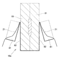
(8) FIGS. 81 to 83 show another embodiment of the hand-grip manufacturing tool 1 according to the present invention, and the front side portion 77 of the standing wall constituting one container 3a is accommodated in the other container 3b. The size of the other container 3b is formed so as to be inserted so as to be inserted into the portion 11.
When configured in this way, when bent at the bent portion 5 so as to close both containers 3a, 3b in which rice or the like is stored, as shown in FIG. 84, the tip of the standing wall of one container 3a Since the side portion 77 enters the housing recess 22 of the other container 3b, the gripping action of the grip formed is obtained by such penetration.
Even when the sizes of the containers 3a and 3b are slightly different from each other, the two containers in the present invention correspond to those that are substantially line-symmetric in the deployed state.
In this way, in the grip manufacturing tool 1 in which the front side portion 77 of the standing wall of one container 3a enters the housing recess 22 of the other container 3b, the contained rice or the like is thereby compacted. Since the action is obtained, the base pieces 6 and 6 of the containers 3a and 3b may be bent and cannot be deformed. When the containers 3a and 3b can be bent and deformed, the stored rice and the like can be compacted from the outside of the containers 3a and 3b.
(9) 図85〜86は本発明に係るお握り製造用具1のその他の実施例を示すものであり、左右の収容器3,3の向き合う立壁部分7b,7bの縁部相互を連結する屈曲部5が比較的長く形成されている。図86は、両収容器3,3を閉じるように前記屈曲部5で折り曲げた状態を示す。
(9) FIGS. 85 to 86 show another embodiment of the hand-grip manufacturing tool 1 according to the present invention, in which bent portions that connect the edges of the standing wall portions 7b and 7b of the right and left containers 3 and 3 to each other are connected. 5 is formed relatively long. FIG. 86 shows a state of being bent at the bent portion 5 so as to close both the containers 3 and 3.
(10) 本発明を構成する収容器3,3の形状は、三角形状や、四角形状、半円形状等、両収容器が展開状態で実質的に線対称を呈するもの全てを採用できる。
(10) As the shape of the containers 3 and 3 constituting the present invention, all of the containers that are substantially line-symmetric in the deployed state, such as a triangular shape, a quadrangular shape, and a semicircular shape, can be adopted.
(11) お握り製造用具1が比較的薄い紙製等の変形し易いものである場合は、収容器3にご飯を入れる際に該収容器3が変形するのを防止するため、展開状態のお握り製造用具1を、図87〜88に示すような金属製や樹脂製等の保持枠79に嵌め入れて収容器3,3にご飯を収容することもある。
(11) When the handgrip manufacturing tool 1 is made of a relatively thin paper or the like and easily deformed, the handgrip in the unfolded state is used to prevent the container 3 from being deformed when rice is put into the container 3. The manufacturing tool 1 may be fitted into a holding frame 79 made of metal or resin as shown in FIGS. 87 to 88 to store rice in the containers 3 and 3.
(12) 左右の収容器3,3で包装された包装お握り18aを持ち運ぶ際、図89に示すように、両収容器3,3の合わせ目94を塞ぐように周方向に粘着性の被覆テープ95を貼着するのがよい。これにより、閉じた両収容器3,3が開くのを防止できると共に、シート状物を介してお握りを製造した場合は、該被覆テープ95によって合わせ目94の気密性を高めることができ、完全包装状態の包装お握りが得られることになる。
なおこの際、該被覆テープ95がフイルム状物に極力接着しないようにするため、フイルム状物の縁部分を、前記合わせ目94から突出しないようにカットするのがよい。
(12) When carrying the packaging handgrip 18a packed in the left and right containers 3 and 3, as shown in FIG. 89, a circumferentially adhesive covering tape so as to close the joint 94 of both containers 3 and 3 95 should be attached. As a result, the closed containers 3 and 3 can be prevented from opening, and when the grip is manufactured via a sheet-like material, the sealing tape 95 can improve the airtightness of the seam 94, and the complete A packaging handful in the packaging state will be obtained.
At this time, in order to prevent the covering tape 95 from adhering to the film-like material as much as possible, it is preferable to cut the edge portion of the film-like material so as not to protrude from the seam 94.
本発明に係るお握り製造用具を上側から見た斜視図である。It is the perspective view which looked at the hand grip manufacturing tool which concerns on this invention from the upper side.
その下側から見た斜視図である。It is the perspective view seen from the lower side.
その平面図である。FIG.
その断面図である。FIG.
その屈曲部を拡大して示す断面図である。It is sectional drawing which expands and shows the bending part.
左右の収容器を閉じた状態を示す断面図である。It is sectional drawing which shows the state which closed the container on either side.
展開状態の左右の収容器上にフイルム状物を被せた状態を示す斜視図である。It is a perspective view which shows the state which covered the film-like object on the container of right and left of the expansion | deployment state.
フイルム状物を押し込んで形成した収容凹部の底面に具を載せた状態を示す斜視図である。It is a perspective view which shows the state which mounted the tool on the bottom face of the accommodation recessed part formed by pushing in the film-like thing.
収容凹部にご飯を収容した状態を示す断面図である。It is sectional drawing which shows the state which accommodated the rice in the accommodation recessed part.
その斜視図である。FIG.
両収容器を閉じるように屈曲部で折り曲げた状態を示す断面図である。It is sectional drawing which shows the state bent by the bending part so that both containers may be closed.
その斜視図である。FIG.
両収容器の略全体を内方に押圧してお握りを締め固めた状態を示す断面図である。It is sectional drawing which shows the state which pressed the substantially whole of both containers inward and compacted the grip.
その締め固め要領を説明する斜視図である。It is a perspective view explaining the compaction point.
締め固めて製造された包装お握りを示す斜視図である。It is a perspective view which shows the packaging handpiece manufactured by compaction.
フイルム状物で被覆されたお握りを取り出す工程を説明する斜視図である。It is a perspective view explaining the process of taking out the grip coated with a film-like object.
取り出されたお握りを示す斜視図である。It is a perspective view which shows the taken out hand grip.
展開状態にある左右の収容器上の全体に板状海苔を被せて収容凹部を形成した状態を示す斜視図である。It is a perspective view which shows the state which covered the plate-shaped nori on the whole of the container on either side in the expansion | deployment state, and formed the accommodation recessed part.
その収容凹部にご飯を収容し且つご飯の上面に具を配置した状態を示す斜視図である。It is a perspective view which shows the state which accommodated rice in the accommodation recessed part, and has arrange | positioned the ingredient | tool on the upper surface of rice.
両収容器を閉じてお握りを締め固めた状態を示す断面図である。It is sectional drawing which shows the state which closed both containers and tightened the grip.
製造されたお握りを示す斜視図である。It is a perspective view which shows the manufactured hand grip.
左右の収容器の収容凹部の底面に板状の具を載せた状態を示す一部欠切斜視図である。It is a partially cutaway perspective view showing a state in which a plate-like tool is placed on the bottom surfaces of the housing recesses of the left and right containers.
収容凹部にご飯を収容し、ご飯上面に具を配置した状態を示す斜視図である。It is a perspective view which shows the state which accommodated rice in the accommodation recessed part and has arrange | positioned the ingredient | tool on the rice upper surface.
両収容器を閉じてお握りを締め固めた状態を示す断面図である。It is sectional drawing which shows the state which closed both containers and compacted the grip.
製造されたお握りを示す斜視図である。It is a perspective view which shows the manufactured hand grip.
本発明に係るお握り製造用具の他の実施例を上側から見た斜視図である。It is the perspective view which looked at the other Example of the grip manufacturing tool which concerns on this invention from the upper side.
その下側から見た斜視図である。It is the perspective view seen from the lower side.
本発明に係るお握り製造用具の他の実施例をその上側から見た斜視図である。It is the perspective view which looked at the other Example of the grip manufacturing tool which concerns on this invention from the upper side.
その下側から見た斜視図である。It is the perspective view seen from the lower side.
本発明に係るお握り製造用具の他の実施例をその上側から見た斜視図である。It is the perspective view which looked at the other Example of the grip manufacturing tool which concerns on this invention from the upper side.
その下側から見た斜視図である。It is the perspective view seen from the lower side.
展開状態にある左右の収容器上にフイルム状物を被せ且つその周縁部分を立壁の外面に分離可能に固定すると共に、形成された収容凹部の底面に具を配置した状態を、蓋片と共に示す斜視図である。A state in which the film-like object is covered on the left and right containers in the unfolded state and the peripheral portion thereof is separably fixed to the outer surface of the standing wall, and the tool is arranged on the bottom surface of the formed accommodating recess, together with the lid piece. It is a perspective view.
左右の収容凹部の底面に配置した具の上に蓋片を被せた状態を示す斜視図である。It is a perspective view which shows the state which covered the cover piece on the tool arrange | positioned at the bottom face of a right-and-left accommodation recessed part.
フイルム状物の周縁部分を立壁の外面に分離可能に固定する他の実施例を、蓋片を被せた状態で示す斜視図である。It is a perspective view which shows the other Example which fixes the peripheral part of a film-like thing to the outer surface of a standing wall so that separation | detachment is possible, in the state which covered the cover piece.
フイルム状物の周縁部分を立壁の外面に分離可能に固定するその他の実施例を、蓋片を被せた状態で示す斜視図である。It is a perspective view which shows the other Example which fixes the peripheral part of a film-like thing to the outer surface of a standing wall so that isolation | separation is possible in the state which covered the cover piece.
蓋片が被せられたお握り製造用具を包装袋に納めて後、これを内箱に収容し、その後、該内箱を外箱に納める工程を説明する斜視図である。It is a perspective view explaining the process of storing the hand-grip manufacturing tool with which the cover piece was covered in the packaging bag, accommodating this in an inner box, and storing this inner box in an outer box after that.
製造された2個のお握りを内箱に収容して後、内箱を外箱に納める工程を説明する斜視図である。It is a perspective view explaining the process of accommodating an inner box in an outer box after accommodating two manufactured grips in an inner box.
本発明に係るお握り製造用具のその他の実施例を上側から見た斜視図である。It is the perspective view which looked at the other Example of the grip manufacturing tool which concerns on this invention from the upper side.
その下側から見た斜視図である。It is the perspective view seen from the lower side.
本発明に係るお握り製造用具のその他の実施例を上側から見た斜視図である。It is the perspective view which looked at the other Example of the grip manufacturing tool which concerns on this invention from the upper side.
その下側から見た斜視図である。It is the perspective view seen from the lower side.
本発明に係るお握り製造用具のその他の実施例を示す底面図である。It is a bottom view which shows the other Example of the grip manufacturing tool which concerns on this invention.
本発明に係るお握り製造用具のその他の実施例を示す底面図である。It is a bottom view which shows the other Example of the grip manufacturing tool which concerns on this invention.
本発明に係るお握り製造用具のその他の実施例を上側から見た斜視図である。It is the perspective view which looked at the other Example of the grip manufacturing tool which concerns on this invention from the upper side.
その下側から見た斜視図である。It is the perspective view seen from the lower side.
左右の収容器を閉じてお握りを締め固めた状態を示す断面図である。It is sectional drawing which shows the state which closed the container on either side and was compacted.
製造されたお握りを示す斜視図である。It is a perspective view which shows the manufactured hand grip.
展開状態にある左右の収容器上にシート状物を被せた後に、形成した収容凹部にご飯を収容した状態を示す斜視図である。It is a perspective view which shows the state which accommodated the rice in the accommodation recessed part formed, after covering a sheet-like object on the container on either side in the expansion | deployment state.
左右の収容器を閉じてお握りを締め固めた状態を示す斜視図である。It is a perspective view which shows the state which closed the container on either side and tightened the grip.
基片に切り目が設けられた本発明に係るお握り製造用具を示す底面図である。It is a bottom view which shows the hand-grip manufacturing tool which concerns on this invention by which the notch was provided in the base piece.
基片に切り目が設けられた本発明に係るお握り製造用具の他の実施例を示す底面図である。It is a bottom view which shows the other Example of the grip manufacturing tool which concerns on this invention by which the notch was provided in the base piece.
基片に切り目が設けられた本発明に係るお握り製造用具のその他の実施例を示す底面図である。It is a bottom view which shows the other Example of the grip manufacturing tool which concerns on this invention by which the notch was provided in the base piece.
基片に切り目が設けられた本発明に係るお握り製造用具のその他の実施例を示す底面図である。It is a bottom view which shows the other Example of the grip manufacturing tool which concerns on this invention by which the notch was provided in the base piece.
基片に切り目が設けられた本発明に係るお握り製造用具のその他の実施例を示す底面図である。It is a bottom view which shows the other Example of the grip manufacturing tool which concerns on this invention by which the notch was provided in the base piece.
基片に切り目が設けられた本発明に係るお握り製造用具のその他の実施例を示す底面図である。It is a bottom view which shows the other Example of the grip manufacturing tool which concerns on this invention by which the notch was provided in the base piece.
基片に切り目が設けられた本発明に係るお握り製造用具を示す底面図である。It is a bottom view which shows the hand-grip manufacturing tool which concerns on this invention by which the notch was provided in the base piece.
立壁に切り取り線が設けられた本発明に係るお握り製造用具を示す斜視図である。It is a perspective view which shows the grip manufacturing tool which concerns on this invention in which the cut-off line was provided in the standing wall.
そのお握り製造用具を用いて製造された包装お握りを示す斜視図である。It is a perspective view which shows the packaging hand grip manufactured using the hand grip manufacturing tool.
切り取り線で立壁部分を切断して収容器上側部分を折り曲げた状態を示す斜視図である。It is a perspective view which shows the state which cut | disconnected the standing wall part with the cut line and bent the container upper part.
その後、フイルム状物を剥がしてお握りの上側部分を露出させた状態を示す断面図である。Then, it is sectional drawing which shows the state which peeled off the film-like thing and exposed the upper part of the grip.
収容器上側部分を取り除いた状態を示す斜視図である。It is a perspective view which shows the state which removed the container upper part.
矩形状の収容器の立壁部分に切り取り線を設けたお握り製造用具を示す斜視図である。It is a perspective view which shows the grip manufacturing tool which provided the tear line in the standing wall part of the rectangular container.
矩形状の収容器の立壁部分に切り取り線を設けたお握り製造用具の他の実施例を示す斜視図である。It is a perspective view which shows the other Example of the grip manufacturing tool which provided the tear line in the standing wall part of the rectangular container.
そのお握り製造用具を用いて製造された包装お握りを示す斜視図である。It is a perspective view which shows the packaging hand grip manufactured using the hand grip manufacturing tool.
その包装お握りの収容器上側部分を取り除いた状態を示す斜視図である。It is a perspective view which shows the state which removed the container upper part of the package hand.
更に収容器中間部分を取り除いた状態を示す斜視図である。Furthermore, it is a perspective view which shows the state which removed the container intermediate part.
切り取り線の他の例を示す正面図である。It is a front view which shows the other example of a cut line.
切り取り線のその他の例を示す正面図である。It is a front view which shows the other example of a cut line.
切り取り線のその他の例を示す一部欠切正面図である。It is a partially notched front view which shows the other example of a cut line.
立壁部分に切り取り線を設けたお握り製造用具の他の実施例を示す斜視図である。It is a perspective view which shows the other Example of the hand-grip manufacturing tool which provided the cutoff line in the standing wall part.
そのお握り製造用具を用いて製造された包装お握りの収容器上側部分を折り曲げた状態を示す斜視図である。It is a perspective view which shows the state which bent the container upper part of the packaging hand grip manufactured using the hand grip manufacturing tool.
立壁部分に切り取り線が設けられ且つ基片に折り曲げ線が設けられたお握り製造用具を示す斜視図である。It is a perspective view which shows the hand-grip manufacturing tool by which the cut-off line was provided in the standing wall part, and the bending line was provided in the base piece.
立壁部分に切り取り線が設けられ且つ基片に折り曲げ線が設けられたお握り製造用具の他の実施例を示す底面図である。It is a bottom view which shows the other Example of the hand-grip manufacturing tool by which the cut line was provided in the standing wall part, and the bending line was provided in the base piece.
基片に折り曲げ線が設けられたお握り製造用具を用いて製造した包装お握りの収容器上側部分を折り曲げた状態を示す斜視図である。It is a perspective view which shows the state which bent the container upper part of the packaging hand grip manufactured using the hand grip manufacturing tool in which the bending line was provided in the base piece.
立壁部分に切り取り線が設けられたお握り製造用具のその他の実施例を示す斜視図である。It is a perspective view which shows the other Example of the grip manufacturing tool by which the cut-off line was provided in the standing wall part.
立壁部分に切り取り線が設けられたお握り製造用具のその他の実施例を示す斜視図である。It is a perspective view which shows the other Example of the grip manufacturing tool by which the cut-off line was provided in the standing wall part.
立壁部分に切り取り線が設けられたお握り製造用具のその他の実施例を示す斜視図である。It is a perspective view which shows the other Example of the grip manufacturing tool by which the cut-off line was provided in the standing wall part.
立壁部分に切り取り線が設けられたお握り製造用具のその他の実施例を示す斜視図である。It is a perspective view which shows the other Example of the grip manufacturing tool by which the cut-off line was provided in the standing wall part.
立壁部分に切り取り線が設けられたお握り製造用具のその他の実施例を示す斜視図である。It is a perspective view which shows the other Example of the grip manufacturing tool by which the cut-off line was provided in the standing wall part.
立壁を櫛刃状に形成した本発明に係るお握り製造用具を示す斜視図である。It is a perspective view which shows the grip manufacturing tool which concerns on this invention which formed the standing wall in the shape of a comb blade.
一方の収容器の立壁の先側部分が他方の収容器の収容部内に挿入されるように構成されたお握り製造用具を、両収容器を閉じた状態で示す断面図である。It is sectional drawing which shows the handle manufacturing tool comprised so that the front side part of the standing wall of one container may be inserted in the accommodating part of the other container in the state which closed both containers.
そのお握り製造用具を示す斜視図である。It is a perspective view which shows the grip manufacturing tool.
その平面図である。FIG.
その両収容器を閉じてお握りを締め固めた状態を示す断面図である。It is sectional drawing which shows the state which closed the container and tightened the grip.
屈曲部を比較的長く形成した本発明に係るお握り製造用具を上側から見た斜視図である。It is the perspective view which looked at the grip manufacturing tool which concerns on this invention which formed the bending part comparatively long from the upper side.
その左右の収容部を閉じると共にお握りを締め固めた状態を示す断面図である。It is sectional drawing which shows the state which closed the left and right accommodating parts, and compacted the grip.
展開状態のお握り製造用具を、これを嵌め入れる保持枠と共に示す斜視図である。It is a perspective view which shows the grip manufacturing tool of an unfolded state with the holding frame which inserts this.
展開状態のお握り製造用具を保持枠に嵌め入れた状態を示す斜視図である。It is a perspective view which shows the state which fitted the holding | grip manufacturing tool of the unfolded state in the holding frame.
両収容器の合わせ目を被覆テープで覆ってなる包装お握りを示す斜視図である。It is a perspective view which shows the packaging hand which covers the seam of both containers with a covering tape.
符号の説明Explanation of symbols
1 お握り製造用具
3 収容器
5 屈曲部
6 基片
7 立壁
7b 立壁部分
16 開口
17 押圧片
18 お握り
21 フイルム状物
22 収容凹部
25 具
75 切り目
80 切り取り線
82 折り曲げ線
87 立壁部分
DESCRIPTION OF SYMBOLS 1 Hand grip manufacturing tool 3 Container 5 Bending part 6 Base piece 7 Standing wall 7b Standing wall part 16 Opening 17 Pressing piece 18 Grasping 21 Film-like object 22 Containing recessed part 25 Tool 75 Cut 80 Cutting line 82 Bending line 87 Standing wall part