JP2005295932A - Traveling vehicle - Google Patents
Traveling vehicle Download PDFInfo
- Publication number
- JP2005295932A JP2005295932A JP2004119000A JP2004119000A JP2005295932A JP 2005295932 A JP2005295932 A JP 2005295932A JP 2004119000 A JP2004119000 A JP 2004119000A JP 2004119000 A JP2004119000 A JP 2004119000A JP 2005295932 A JP2005295932 A JP 2005295932A
- Authority
- JP
- Japan
- Prior art keywords
- turning
- gear
- traveling
- clutch
- operation tool
- Prior art date
- Legal status (The legal status is an assumption and is not a legal conclusion. Google has not performed a legal analysis and makes no representation as to the accuracy of the status listed.)
- Pending
Links
Images





Landscapes
- Guiding Agricultural Machines (AREA)
- Harvester Elements (AREA)
- Non-Deflectable Wheels, Steering Of Trailers, Or Other Steering (AREA)
Abstract
【課題】単一の操作具により旋回操作と旋回力アップ操作ができ、しかも他の作業も安全に行える構成を備えたコンバインなどの走行車両を提供すること。
【解決手段】植立穀稈を刈り取る刈取装置9と車輪3の回転数を旋回制動圧により調整する旋回クラッチ82を有する旋回性能を変更する旋回装置14と操向操作具21の後方向への操作により刈取装置9を所定値以上上昇させた後、さらに該操向操作具21の後方向への操作を行い、次いで左右方向へ操作させた場合に、該操向操作具21の左右の操向操作量に応じた前記旋回制動圧を更に所定値加算した出力を行う制御を行う制御装置100を備えた走行車両である。
【選択図】図5The present invention provides a traveling vehicle such as a combine that has a configuration in which a turning operation and a turning force-up operation can be performed with a single operation tool, and other operations can be performed safely.
A swiveling device having a swiveling device that cuts planted cereals and a turning clutch that adjusts the rotational speed of a wheel by turning braking pressure. After raising the reaping device 9 by a predetermined value or more by an operation, when the steering operation tool 21 is further operated in the backward direction and then in the horizontal direction, the left and right operation of the steering operation tool 21 is performed. It is a traveling vehicle provided with the control apparatus 100 which performs control which performs the output which further added the predetermined value to the said turning braking pressure according to direction operation amount.
[Selection] Figure 5
Description
本発明は、コンバインなどの走行車両に関するものである。 The present invention relates to a traveling vehicle such as a combine.
例えばクローラを走行手段とする作業車両として、農業用のコンバインを例に従来の技術を説明する。コンバインは無端帯状のクローラを有し、水田など軟弱な圃場でも自由に走行して刈取作業などの農業作業を可能としている。 For example, as a work vehicle using a crawler as a traveling means, a conventional technique will be described taking an agricultural combine as an example. The combine has an endless belt-like crawler, and can run freely even in a soft field such as paddy fields to enable agricultural work such as mowing.
コンバインは動力源としてエンジンを搭載し、エンジンの発生する動力をコンバインの走行、刈取、脱穀などに使用するが、そのクローラは、エンジンの動力を走行トランスミッション装置により変速して駆動する。走行トランスミッションは、静油圧式無段変速装置、歯車列機械的変速手段、差動歯車装置、クラッチ手段、ブレーキ手段などにより構成され、また、操向操作レバーを左右に傾斜させる操作で緩旋回機構とブレーキ旋回機構と急旋回機構を選択できる機構を備えている。 The combine is equipped with an engine as a power source, and the power generated by the engine is used for traveling, harvesting, threshing, etc. of the combine. The crawler drives the engine power by shifting it with a traveling transmission device. The traveling transmission is composed of a hydrostatic continuously variable transmission, a gear train mechanical transmission means, a differential gear device, a clutch means, a brake means, etc., and a gentle turning mechanism by tilting the steering operation lever to the left and right And a mechanism capable of selecting a brake turning mechanism and a sudden turning mechanism.
これら左右方向への旋回性能の向上のために旋回内側の走行駆動体の制動圧を通常旋回時より上げるための手段として旋回力アップスイッチ等の操作手段を設けて、その操作に応じて急旋回できるようにしている構成が知られている(下記特許文献1、2)。
しかし、前記特許公開公報記載のコンバインの構成は、独立して旋回力調整が行えるメリットはあるものの旋回力アップのために別途操作手段を使用しなければならないので、操作に熟練しないと旋回時の操作性が十分でないことや、刈取装置を降下させたまま急旋回させて刈取装置に損傷を来すなどの不具合が生じる可能性がある。 However, although the structure of the combine described in the above-mentioned patent publication has an advantage that the turning force can be adjusted independently, it is necessary to use a separate operation means for increasing the turning force. There is a possibility that inconveniences such as insufficient operability and damage to the harvesting device by turning it sharply while lowering the harvesting device may occur.
本発明の課題は、単一の操作具により旋回操作と旋回力アップ操作ができ、しかも他の作業も安全に行える構成を備えたコンバインなどの走行車両を提供することである。 An object of the present invention is to provide a traveling vehicle such as a combine that has a configuration in which a turning operation and a turning force-up operation can be performed with a single operation tool and other operations can be performed safely.
請求項1記載の発明は、車体2に設けられたエンジンと、該エンジンからの駆動力を変速して得られた動力で駆動され、走行方向に向かって左右に設けられた旋回可能な走行駆動体3と、植立穀稈を刈り取る刈取装置9と、前記走行駆動体3を左右方向に旋回させる左右方向への操作と前記刈取装置9を昇降させる前後方向への操作を行う操向操作具21と、該操向操作具21の操作量に応じて旋回内側の走行駆動体3の回転数を変更可能な旋回装置14と、刈取装置9が所定値以上の上昇位置にある状態で、操向操作具21を後側に操作しながら左右方向へ操作させた場合又は操向操作具21を後側に操作した後で左右方向へ操作させた場合に、実際に操作された操向操作具21の左右方向の操作位置に対する旋回半径よりも小さい旋回半径で旋回するように制御を行う制御装置100とを備えた走行車両である。
The invention described in
請求項1記載の発明によれば、刈取装置9が所定値以上の上昇位置にある状態では、操向操作具21を後側に操作してから左右方向に操作したとき又は操向操作具21を後側に操作した後で左右方向へ操作させたときには、実際に操作された操向操作具21の左右方向の操作位置に対する旋回半径よりも小さい旋回半径で旋回するような制御を行う。 According to the first aspect of the present invention, in the state where the reaping device 9 is in the raised position of a predetermined value or more, the steering operation tool 21 is operated in the left-right direction after the steering operation tool 21 is operated rearward or the steering operation tool 21. When the steering wheel 21 is operated in the left-right direction after being operated to the rear side, control is performed so that the steering operation tool 21 that is actually operated turns with a turning radius smaller than the turning radius with respect to the operation position in the left-right direction.
請求項2記載の発明は、刈取装置9には刈り取った穀稈を検出する穀稈検出手段を備えており、該穀稈検出手段が穀稈を検出中であると、制御装置100は、前記実際に操作された操向操作具21の左右方向の操作位置に対する旋回半径よりも小さい旋回半径で旋回する制御を行なわない請求項1記載の走行車両である。
The invention according to
請求項2記載の発明によれば、穀稈検出手段が穀稈を検出中であると、制御装置100は、前記実際に操作された操向操作具21の左右方向の操作位置に対する旋回半径よりも小さい旋回半径で旋回する制御を行なわないようにする。
According to the second aspect of the present invention, when the culm detection means is detecting the culm, the
請求項3記載の発明は、車体2に設けられたエンジンと、該エンジンからの駆動力を変速して得られた動力で駆動され、走行方向に向かって左右に設けられた旋回可能な走行駆動体3と、植立穀稈を刈り取る刈取装置9と、該操向操作具21の操作量に応じて旋回内側の走行駆動体3の回転数を変更可能な旋回装置14と、刈取装置9が所定値以上の上昇位置にある状態で、操向操作具21を左右方向に操作した後で後側に操作させた場合に、実際に操作された操向操作具21の左右方向の操作位置に対する旋回半径よりも小さい旋回半径で旋回するように制御を行う制御装置100とを備えた走行車両である。
The invention according to
請求項3記載の発明によれば、刈取装置9が所定値以上の上昇位置にある状態で、操向操作具21を左右方向に操作した後で後側に操作させた場合に、実際に操作された操向操作具21の左右方向の操作位置に対する旋回半径よりも小さい旋回半径で旋回するように制御を行う。 According to the third aspect of the present invention, when the reaping device 9 is operated to the rear side after operating the steering operation tool 21 in the left-right direction in a state where the reaping device 9 is in the raised position of a predetermined value or more, the operation is actually performed. Control is performed so as to turn with a turning radius smaller than the turning radius with respect to the operation position in the left-right direction of the steering operation tool 21 that has been made.
請求項4記載の発明は、刈取装置9には刈り取った穀稈を検出する穀稈検出手段を備えており、該穀稈検出手段が穀稈を検出中であると、制御装置100は前記実際に操作された操向操作具21の左右方向の操作位置に対する旋回半径よりも小さい旋回半径で旋回する制御を行なわない請求項3記載の走行車両である。
According to a fourth aspect of the present invention, the reaping device 9 is provided with a culm detection means for detecting the culm that has been harvested. The traveling vehicle according to
請求項4記載の発明によれば、穀稈検出手段が穀稈を検出中であると、制御装置100は、前記実際に操作された操向操作具21の左右方向の操作位置に対する旋回半径よりも小さい旋回半径で旋回する制御を行なわないようにする。
According to the invention of
請求項1記載の発明によれば、刈取装置9が所定値以上上昇している状態において、刈取装置9を上昇させる操向操作具21を更に後側に操作させて上昇させながら左右方向に操作させた場合又は操向操作具21を後側に操作した後で左右方向へ操作させた場合には実際に操作された操向操作具21の左右方向の操作位置に対する旋回半径よりも小さい旋回半径で旋回するような制御を行うので、急な障害物からの回避動作が可能になる。また、既に上昇している刈取装置9を、操向操作具21を左右方向に操作することで、さらに上昇させることができるので、刈取装置9と圃場面などとの距離が長くなり安全性が高まる。さらに、旋回半径を小さくするために別途スイッチなどの部材をを設ける必要がなく、走行車両のコストダウンができる。 According to the first aspect of the present invention, in the state where the reaping device 9 is raised by a predetermined value or more, the steering operation tool 21 for raising the reaping device 9 is further operated to the rear side and operated in the left-right direction. Or when the steering operation tool 21 is operated in the left-right direction after operating the steering operation tool 21 to the rear side, the turning radius smaller than the turning radius with respect to the operation position in the left-right direction of the steering operation tool 21 actually operated. Since control is performed so as to turn the vehicle, it is possible to avoid a sudden obstacle. Moreover, since the reaping device 9 that has already been lifted can be further raised by operating the steering operation tool 21 in the left-right direction, the distance between the reaping device 9 and the field scene becomes longer and safety is increased. Rise. Furthermore, there is no need to provide a separate member such as a switch in order to reduce the turning radius, and the cost of the traveling vehicle can be reduced.
請求項2記載の発明によれば、請求項1記載の発明の効果に加えて、穀稈センサが植立穀稈を検出していると、上記旋回力アップの制御は行わないようにして、刈取作業中の誤操作を未然に防ぐことができる。
According to the invention of
請求項3記載の発明によれば、刈取装置9が所定値以上上昇している状態において、刈取装置9を上昇させた操向操作具21を左右方向に操作することで旋回半径を小さくすることができ、急な障害物からの回避動作が可能になる。また、既に上昇している刈取装置9を、操向操作具21を左右方向に操作することで、さらに上昇させることができるので、刈取装置9と圃場面などとの距離が長くなり安全性が高まる。さらに、旋回半径を小さくするために別途スイッチなどの部材をを設ける必要がなく、走行車両のコストダウンができる。 According to the third aspect of the present invention, the turning radius is reduced by operating the steering operation tool 21 in which the reaping device 9 is raised in the left-right direction in a state where the reaping device 9 is elevated by a predetermined value or more. It is possible to avoid a sudden obstacle. Moreover, since the reaping device 9 that has already been lifted can be further lifted by operating the steering operation tool 21 in the left-right direction, the distance between the reaping device 9 and the field scene becomes longer and safety is increased. Rise. Furthermore, there is no need to provide a separate member such as a switch in order to reduce the turning radius, and the cost of the traveling vehicle can be reduced.
請求項4記載の発明によれば、請求項3記載の発明の効果に加えて、穀稈センサが植立穀稈を検出していると、上記旋回力アップの制御は行わないようにして、刈取作業中の誤操作を未然に防ぐことができる。
According to the invention of
以下、本発明の実施の形態を図面を用いて具体的に説明する。
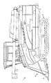
図1は本発明のコンバインの左側面図である。
図1に示すように、コンバイン1の車体フレーム2の下部側に土壌面を走行する左右一対の走行装置(以下、走行クローラと称す。)3を有する走行装置本体4を配設し、車体フレーム2の前端側に分草杆8を備えた刈取装置9が設けられている。該刈取装置9は車体フレーム2の上方の支点を中心にして上下動する刈取装置支持フレーム7で支持されているので、コンバイン1に搭乗したオペレータが操縦席20の操向レバー21を前後に傾倒操作することにより、刈取装置支持フレーム7と共に上下に昇降する構成である。
Hereinafter, embodiments of the present invention will be described in detail with reference to the drawings.
FIG. 1 is a left side view of the combine of the present invention.
As shown in FIG. 1, a
車体フレーム2の上方には、刈取装置9から搬送されてくる穀稈を引き継いで搬送して脱穀、選別する脱穀装置10と該脱穀装置10で脱穀選別された穀粒を一時貯溜するグレンタンク13が載置され、該グレンタンク13の後部にオーガ15を連接して、グレンタンク13内の穀粒をコンバイン1の外部に排出する構成としている。
Above the
すなわち、コンバイン1はオペレータが操縦席20において主変速HSTレバー23および副変速レバー22を操作し、エンジン(図示せず)の動力を図2に示す走行トランスミッションケース12内の主変速機の走行用HST18および副変速装置24の歯車変速手段を介して変速し、左右の走行クローラ3,3に伝動して任意の速度で走行する。
That is, in the
また、コンバイン1は、オペレータが操縦席20において操向レバー21を左右に傾倒操作することにより各種旋回走行することができる。すなわち、操向レバー21をコンバイン1を旋回させようとする方向に傾倒操作することにより、図2に示す走行ミッションケース12内のサイドクラッチ44と旋回クラッチ82が作動し、左右のクローラ駆動スプロケット16L,16Rに選択的に伝動されるので、左右の走行クローラ3,3に速度差が与えられて走行方向の変更が行われる構成としている。
Further, the
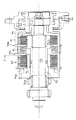
本実施の形態のコンバイン1の走行ミッション装置14を展開して示す断面図を図2に示す。また、図3に差動歯車装置のギアの回転数の関係図を示す。図4にはクラッチ軸70部分の拡大図を示す。
FIG. 2 shows a cross-sectional view of the traveling mission device 14 of the
走行ミッション装置14は、図2に示す油圧式無段変速装置(走行用HST)18の出力軸17、ミッション入力軸27、ミッションカウンタ軸33、サイドクラッチ軸41、ホイール軸11からなる走行トランスミッション基本伝動系と、クラッチ軸70及び差動歯車機構支持軸50を備えた走行ミッション差動伝動系(補助伝動系)を備えている。
The traveling transmission device 14 is a traveling transmission basic comprising an
まず、走行ミッション装置14の走行トランスミッション基本伝動系を主に図2で説明する。
図示しないエンジンからの回転駆動力が走行用HST18に伝動され、正・逆転の切換えや変速回転動力が出力軸17から出力される構成としている。そして、主変速レバー23により走行用HST18の増減速の変速と前後進(正・逆転の切換え)の切換えができる構成としている。
そして、操向レバー21を操作して、後述のサイドクラッチ44の「入」・「切」と差動歯車装置6を変速させて旋回操行ができる構成としている。
First, the traveling transmission basic transmission system of the traveling mission apparatus 14 will be described mainly with reference to FIG.
A rotational driving force from an engine (not shown) is transmitted to the traveling
Then, the steering lever 21 is operated to shift the “on” / “off” of the side clutch 44 described later and the
走行ミッションケース12内には、副変速装置24とサイドクラッチ装置25と差動歯車装置6が設けられ、これらの装置の伝動下手側の左右のホイールシャフト11L,11Rから駆動スプロケット16L,16Rを介して左右の走行クローラ3,3を駆動する構成になっている。
In the
走行用HST18の出力軸17の広幅伝動ギア26からの動力はHSTカウンタ軸60のカウンタギア61に伝達され、該カウンタギア61から副変速装置24のミッション入力軸27上の伝動ギア62に動力が伝動される。
The power from the wide transmission gear 26 of the
副変速装置24のミッション入力軸27上に一体に設けられた大ギア28と中ギア29と小ギア30とミッションカウンタ軸33上に設けられた変速大ギア34、変速中ギア35及び変速小ギア36から構成される。ミッション入力軸27上に、一体に設けられたギア28〜30は副変速レバー22の操作でミッション入力軸27の軸方向に摺動自在に軸装して変速可能に構成している。そして、上記ミッション入力軸27は、端部を走行ミッションケース12から外側に延長して刈取伝動プーリ(図示せず)を軸着して車速に同調した回転動力を刈取装置9などの回転各部に入力できる構成としている。
The
また、ミッションカウンタ軸33は、前記ミッション入力軸27の伝動下手側に軸架し、変速大ギア34、変速中ギア35、変速小ギア36及び伝動ギア37をそれぞれ軸着している。ミッションカウンタ軸33のギア34〜37は不動で、ミッション入力軸27上に、一体に設けられた大ギア28と中ギア29と小ギア30が図示しないシフタにより摺動するので、ミッションカウンタ軸33の変速大ギア34は前記ミッション入力軸27の小ギア30に噛合し、変速中ギア35はミッション入力軸27の中ギア29に噛合し、変速小ギア36はミッション入力軸27の大ギア28にそれぞれ噛合する。さらに伝動ギア37はサイドクラッチ装置25のセンターギア40に常時噛合している。
The mission counter shaft 33 is mounted on the lower transmission side of the
サイドクラッチ装置25は、センターギア40を略中心として、その左右に伸びるサイドクラッチ軸41を一体で備えている。該サイドクラッチ軸41上にはそれぞれスリーブ42L,42Rが遊嵌しており、前記センターギア40にはクラッチギア43L,43Rが係合、解放可能な爪40bL,40bRを備えている。また、クラッチギア43L,43Rはスリーブ42L,42Rと一体的に設けられている。
The side clutch device 25 is integrally provided with a side
クラッチギア43L,43Rは減速軸63に遊嵌している伝動ギア64L,64Rに常時噛合しているので、クラッチギア43L,43Rからの動力は伝動ギア64L,64Rからギア63aL,63aRを経由してホイールシャフトギア48L,48Rに伝達され、ホイールシャフトギア48L,48Rからホイールシャフト11L,11Rを経由し、駆動スプロケット16L,16Rから左右の走行クローラ3,3に伝達される。
Since the clutch gears 43L and 43R are always meshed with the transmission gears 64L and 64R that are loosely fitted to the reduction shaft 63, the power from the clutch gears 43L and 43R passes through the gears 63aL and 63aR from the transmission gears 64L and 64R. Is transmitted to the wheel shaft gears 48L and 48R, transmitted from the wheel shaft gears 48L and 48R to the left and right traveling
爪クラッチ式に噛合したクラッチギア43L,43Rとセンターギア40の爪部40bL,40bRからなる構成をそれぞれサイドクラッチ44L,44Rと呼ぶことにする。 The configurations composed of the clutch gears 43L and 43R meshed in the claw clutch type and the claw portions 40bL and 40bR of the center gear 40 will be referred to as side clutches 44L and 44R, respectively.
また、スリーブ42L,42Rと走行ミッションケース12との間にそれぞれベアリングスペーサー45L,45Rを介してスプリング46L,46Rが設けられ、このスプリング46L,46Rによりスリーブ42L,42Rとクラッチギア43L,43Rは常時センターギア40側に付勢されている。そして、旋回時に油圧力でシフタ47L,47Rのいずれかを作動させて対応する前記スプリング46L,46Rのいずれかの付勢力に打ち勝つ方向に移動可能な構成になっている。これにより、旋回内側のサイドクラッチ44L又は44Rが切れる。
In addition, springs 46L and 46R are provided between the sleeves 42L and 42R and the traveling
シフタ47L,47Rは直進走行時には作動せず、サイドクラッチ44L,44Rが共に係合した状態であるので、後述の伝達経路で左右の走行クローラ3,3が等速回転する。また所望の旋回方向に操向レバー21を操作することでシフタ47L又は47Rが作動して、旋回内側のサイドクラッチ44L又は44Rの係合と解放が選択される。
Since the
センターギア40の外周ギア40aはクラッチ軸70上に遊嵌している円筒状回転体72のギア72aと常時噛合している。該円筒状回転体72と爪係合している円筒体72bとクラッチ軸70にスプライン係合している円筒状回転体71との間で多板式摩擦板からなる直進用クラッチ81を構成している。
The outer peripheral gear 40 a of the center gear 40 is always meshed with a
また、円筒状回転体72の外周には円筒状回転体74が遊嵌しており、該円筒状回転体74にはセンターギア40の第三のギア40cに常時係合しているギア74aを備えている。また円筒状回転体74と円筒状回転体71との間で多板式摩擦板からなる旋回用クラッチ82を構成している。直進用クラッチ81と旋回用クラッチ82との間には圧縮バネ75が配置され、該圧縮バネ75の付勢力は直進用クラッチ81が「入」となるように設置されている。
A cylindrical
また、円筒状回転体71の外周には直進用クラッチ81と圧縮バネ75と旋回用クラッチ82の間をそれぞれ仕切る円盤状プレート76a,76bを備えた円筒体76が一体化して設けられている。
A
油口77から圧油の導入がない場合には圧縮バネ75によって円筒状回転体71と円筒状回転体72との間で常時直進用クラッチ81が係合する「入」方向に付勢されている。直進用クラッチ81は常時「入」状態を保ち、旋回用クラッチ82は常時「切」状態を保っている。
When no pressure oil is introduced from the
油口77から圧油の導入があると、ピストン73と円筒体76の円盤状プレート76aと76bがバネ75の付勢力に打ち勝って図2の左側方向にシフトし、直進用クラッチ81は解放(「切」状態)となり、旋回用クラッチ82が係合(「入」状態)になる。
When pressure oil is introduced from the
直進用クラッチ81が「入」の場合は副変速装置24からの駆動力がサイドクラッチ軸41のセンターギア40の外周ギア40aと円筒状回転体72のギア72aを経由して円筒状回転体72、円筒体72b、円筒体76、円筒状回転体71、直進用クラッチ81及びクラッチ軸70を回転させ、該クラッチ軸70と一体の伝動ギア78と、該伝動ギア78に常時係合している差動歯車機構6のリングギア53を回転させる。このとき旋回用クラッチ82が「切」であるのでセンターギア40の第三ギア40cに常時噛合している円筒状回転体74のギア74aの回転動力はクラッチ軸70には伝達されないで円筒状回転体74は空回りする。
When the straight traveling clutch 81 is “ON”, the driving force from the
また、旋回用クラッチ82が「入」の場合は、直進用クラッチ81が「切」となり、クラッチ軸70に遊嵌している円筒状回転体72を空回りさせるが、このときセンターギア40の第三ギア40cからの駆動力が円筒状回転体74のギア74aを経由して円筒状回転体74から旋回用クラッチ82と円筒体76を経由して円筒状回転体71を回転させ、該回転体71の回転でクラッチ軸70を駆動させる。この結果、クラッチ軸70に固定された伝動ギア78が回転して、該伝動ギア78に常時係合している差動歯車装置6のリングギア53を回転させる。
When the turning
差動歯車装置6には、中間ベベルギア52の外周に設けたデフケース54と一体のリングギア53が設けられており、また、支持軸50には側部ベベルギア51L,51Rが回転可能に支持されており、また、側部ベベルギア51L,51Rの外側には左右のサイドギア55L,55Rがそれぞれ固定している。
The
サイドギア55Lは伝動ギア64Lに常噛し、サイドギア55Rは伝動ギア64Rに常噛しており、また伝動ギア64Lとギア63aLは一体であり、伝動ギア64Rとギア63aRは一体である。
The side gear 55L always meshes with the transmission gear 64L, the
図2から明らかなように、直進用クラッチ81と旋回用クラッチ82を同一軸であるクラッチ軸70に設けることにより両クラッチ81、82を択一的に操作できるので、構成が簡素化でき、安価になる。また両クラッチ81、82の切り替えのタイミングを機械的に調整できるので複雑な制御が不要となる。
As can be seen from FIG. 2, since the straight clutch 81 and the turning
上記構成からなる走行ミッション装置14のギア機構において、コンバインの直進時はサイドクラッチ装置25の左右のサイドクラッチ44L,44Rが共に係合したままであり、エンジン動力は副変速装置24のミッションカウンタ軸33に伝達され、該ミッションカウンタ軸33のの出力ギア37を経由してセンターギア40に伝達される。該センターギア40にはサイドクラッチ軸41が共に係合しているので、センターギア40の回転力はクラッチ44L,44Rを介してクラッチギア43L,43Rに伝達され、該クラッチギア43L,43Rに常時係合している伝動ギア64L,64Rに伝達され、伝動ギア64L,64Rから減速軸63のギア63aL,63aRとホイールギア48L,48Rをそれぞれ経由して左右の走行クローラ3が共に回転する。
In the gear mechanism of the traveling mission device 14 configured as described above, the left and right side clutches 44L and 44R of the side clutch device 25 remain engaged when the combine is traveling straight, and the engine power is transmitted to the mission counter shaft of the
副変速レバー22の作動で副変速シフタステー32が副変速装置24のミッション入力軸27のギア28、29、30とそれぞれ対応するミッションカウンタ軸33のギア34、35、36のいずれかの組のギア同士を噛合させて、適切な速度段で直進走行ができる。
By operating the auxiliary transmission lever 22, the auxiliary transmission shifter stay 32 corresponds to the
このとき直進用クラッチ81は「入」で、旋回用クラッチ82は「切」であり、直進時の差動歯車装置6の状態は次の通りである。
(イ)ミッションカウンタ軸33の駆動力がセンタギア40の爪ギア40bL,40bRとを経由してサイドクラッチ装置25のサイドクラッチ44L,44R及びサイドクラッチ軸41のクラッチギア43L,43Rを経由して伝動ギア64L,64Rが共に回転しているので、伝動ギア64L,64Rがそれぞれ噛合している差動歯車装置6のサイドギア55L,55Rは同じ方向に共に等速回転する。従って、サイドギア55L,55Rとそれぞれ一体回転する側部ベベルギア51L,51Rを介してデフケース54と該デフケース54と一体のリングギア53も同じ方向に回転し、前記側部ベベルギア51L,51Rに噛み合っている中間ベベルギア52、52aが支持軸50を中心に回転する。
At this time, the rectilinear clutch 81 is “on” and the turning
(A) The driving force of the transmission counter shaft 33 is transmitted via the side clutches 44L and 44R of the side clutch device 25 and the clutch gears 43L and 43R of the side
(ロ)ミッションカウンタ軸33の駆動力がセンターギア40の外周ギア40aから回転円筒体72に伝達され回転円筒体72と爪係合する円筒体72b、直進用クラッチ81、円筒体76のプレート76a、円筒状回転体71、クラッチ軸70、伝動ギア78及びリングギア53に順次動力伝達され、リングギア53と同じ回転方向にベベルギア52も回転する。
(B) The driving force of the mission counter shaft 33 is transmitted from the outer peripheral gear 40a of the center gear 40 to the rotating
このようにリングギア53は上記(イ)、(ロ)の二系統から回動されるので上記(イ)、(ロ)の二系統からのリングギア53への変速比を同じに設定する。従ってサイドクラッチ44L又は44Rを「切」にしたとき、上記(ロ)の伝動系統からの動力がリングギア53からサイドギア55L,55Rと伝動ギア64L,64R、カウンタギア63aL,63aR、ホイールシャフトギア48L,48Rにそれぞれ伝わるので、ショックが防止される。また、センターギア40と一体の第三ギア40cから、ギア74a、円筒状回転体74に伝達される旋回用の動力は、旋回用クラッチ82で回転している。
Since the
次に前記ギア機構の左旋回時の作動について説明する。
操向レバー21を左側に傾斜させることで、シフタ47Lを作動させ、サイドクラッチ44Lを「切」にすると、図示しない機構により油口77から圧油が導入され、ピストン73と円筒体76が図2の左方向に移動する。この移動により直進用クラッチ81を「切」として、旋回用クラッチ82を「入」とする。溶接で一体構成されたセンターギア40と第三のギア40cの回転力は旋回用クラッチ82の円筒状回転体74の外周に設けられた対応するギア74a、旋回用クラッチ82、円筒体76、円筒状回転体71、クラッチ軸70、伝動ギア78、リングギア53、側部ベベルギア51L、サイドギア55L、減速軸63の伝動ギア64L、ギア63aL、ホイールシャフトギア48L、クローラ駆動スプロケット16Lをそれぞれ経由して左の走行クローラ3を駆動させる。この時、センターギア40の動力はクラッチギア43Rから減速軸63の伝動ギア64R、ギア63aR、ホイールギア48R、クローラ駆動スプロケット16Rをそれぞれ経由して旋回外側の右の走行クローラ3を駆動する。
Next, the operation of the gear mechanism when turning left will be described.
By tilting the steering lever 21 to the left, the
旋回用クラッチ82は、その多板式摩擦板を油圧力を無段階的(連続的)に設定した旋回モードまで制御することができる。なお、この旋回用クラッチ82の摩擦板の油圧力の制御は操縦席20に設けた操向レバー21に付属するポテンショメータ(図示せず)で検出される傾動角度の制御で行うことができる。
The turning
センターギア40の第三のギア40cと円筒状回転体74のギア74aの変速比の関係により、例えば旋回用クラッチ82を完全に接続させた場合にサイドギア55Lの回転数はサイドクラッチ44R側のサイドギア55Rの回転数の−1/3になり、急旋回(スピンターン)状態になるように設定しているので、緩旋回からブレーキ旋回と急旋回への移行が可能になっている。
Due to the relationship between the gear ratio of the third gear 40c of the center gear 40 and the gear 74a of the cylindrical
すなわち、図2に示すように左旋回時には旋回外側であるサイドクラッチ44Rが「入」状態であるので、ホイールシャフトギア48Rの回転がクラッチギア43Rから一定回転で伝動されるとともに、クラッチギア43Rの回転はサイドギア55Rを一定回転で伝動する。一方、リングギア53の回転数が旋回用クラッチ82の摩擦力が強くなるに従い減速されていくと、それに比例してサイドギア55Lの回転数が減少していく。リングギア53の回転数がサイドギア55Rの1/2になると、サイドギア55Lはゼロ回転となり、サイドギア55Lからホイールシャフトギア48Lを経由する回転数がゼロになり、左走行クローラ3にブレーキが利いているのではないが左走行クローラ3が回転しない、いわゆるブレーキ旋回が行われる。
That is, as shown in FIG. 2, when turning left, the side clutch 44R outside the turn is in the “on” state, so that the rotation of the wheel shaft gear 48R is transmitted from the clutch gear 43R at a constant rotation, and the clutch gear 43R The rotation transmits the
さらにリングギア53が減速していくと、サイドギア55Rの回転方向に対してサイドギア55Lは逆転回転をして左走行クローラ3が逆回転し、いわゆる急旋回が行われる。
When the
サイドギア55Rの回転数に対してサイドギア55Lの逆転回転数は、ギア40cとギア74aの変速比を図3の点Xに設定していると、サイドギア55Lがサイドギア55Rに対して−1/3スピンターンまで実行可能な逆転回転数まで設定が可能である。
また、右旋回選択時はサイドクラッチ44Rを「切」にすることで、前記左旋回と全く逆の作動が走行ミッション装置14で行われる。
The reverse rotation speed of the side gear 55L with respect to the rotation speed of the
Further, when the right turn is selected, the side transmission 44R is set to “OFF”, so that the traveling mission device 14 performs an operation completely opposite to the left turn.
上記したような副変速装置24と旋回用クラッチ82との間に比較的簡単な構成のギア変速装置19を介装し、旋回用クラッチ82の摩擦板の係合圧を調整することで、緩旋回からブレーキ旋回及び−1/3の急旋回まで実行可能な状態に切り替えられるようにした。上記ミッション入力軸27には刈取装置への出力軸65がスプライン係合している。
A gear transmission 19 having a relatively simple configuration is interposed between the
上記差動歯車機構6を有する変速装置を備えた本実施例のコンバインの旋回制御装置100を図5の制御ブロック図に示す。
FIG. 5 is a control block diagram showing a combine
本実施例は、操向操作具(以下、パワステレバー21という)を前後に倒すことで刈取装置9を昇降制御できる周知の機構を備えているが、パワステ上げスイッチ68とパワステ下げスイッチ69は刈取装置9を昇降制御しているときのパワステレバー21の前後への傾倒動作を検出するセンサである。
The present embodiment is provided with a known mechanism that can raise and lower the reaping device 9 by tilting a steering operation tool (hereinafter referred to as a power steering lever 21) back and forth, but the power
さらに、本実施例は、パワステレバー21を左方向と右方向に倒すことで、それぞれ左旋回と右旋回ができる周知の構成を備えているが、パワステレバー21の左右への傾倒角度を検出するポテンショメータからなるパワステ左右センサ101を備えている。 In addition, the present embodiment has a known configuration in which the power steering lever 21 can be turned left and right by tilting the power steering lever 21 leftward and rightward. A power steering left and right sensor 101 composed of a potentiometer is provided.
穀稈センサ(前左)102と穀稈センサ(前右)103は植立穀稈の多条刈りを行う場合に、左端条又は右端条の穀稈の有無を検出するものであり、当該穀稈センサ102,103が圃場に植立した穀稈を検出しないときだけ、後述する旋回力がアップする構成になっている。また、穀稈センサ102,103は刈取装置9の左側の搬送始端部と右側の搬送始端部にそれぞれ設けられる。
また刈取装置9の昇降位置を検出する刈取昇降位置センサ105を用いて、その昇降制御動作を調整することができる。
The cereal sensor (front left) 102 and the cereal sensor (front right) 103 detect the presence or absence of the left end or right end portion of the cereal when the planted culm is subjected to multi-row cutting. Only when the
Moreover, the raising / lowering control operation | movement can be adjusted using the cutting raising / lowering
また、パワステレバー21の左右への傾倒で制御装置100は左右のサイドクラッチ44L,44Rのいずれか対応する旋回内側のサイドクラッチを切るようにクラッチ切換バルブ108,109に出力し、緩旋回時、ブレーキ旋回時及び急旋回時には同時に直進用クラッチ81を切りにして旋回用クラッチ82を入りにする比例ソレノイド110に出力する。
Further, when the power steering lever 21 is tilted to the left or right, the
また、本実施例では緩旋回モードを選択するスイッチ104を設けている。前記緩旋回モードスイッチ104がオンであると、パワステレバー21を左又は右へ傾倒させたときに緩旋回モードでしか旋回できないように規制するためのスイッチである。
In this embodiment, a
本実施例の特徴は、パワステレバー21を後方に倒して刈取装置9を所定高さ以上上昇させた状態にあるとき、更にパワステレバー21を後ろに引きながら又はパワステレバー21を後ろに引いた後で、パワステレバー21を左又は右へ傾倒させると、パワステレバー21の傾倒角度に応じてブレーキ旋回までの旋回力アップが図れるようにしている。 The feature of the present embodiment is that when the power steering lever 21 is tilted backward and the cutting device 9 is raised by a predetermined height or more, the power steering lever 21 is further pulled backward or the power steering lever 21 is pulled backward. Thus, when the power steering lever 21 is tilted to the left or right, the turning force up to the brake turning can be increased according to the tilting angle of the power steering lever 21.
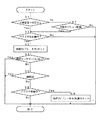
また、緩旋回モードを選択するスイッチ104をオンとして緩旋回モードを選択しているときは前記旋回力アップの制御は行わない。この場合の制御フローチャートを図6に示す。
Further, when the slow turning mode is selected by turning on the
図6の制御フローチャートで、「刈取位置>所定以上」のステップは、刈取装置9が所定高さ以上上昇していることを刈取昇降位置センサ105で検出する。また、図6では穀稈センサ(前左)102と穀稈センサ(前右)103が植立穀稈を検出していない時には、刈取装置9は刈取作業を行っていないと判断して上記旋回力アップの制御に入ることができる。また、穀稈センサ(前左)102と穀稈センサ(前右)103が植立穀稈を検出していると刈取装置9が刈り取り作業を実施中であるので、たとえ刈取装置9が所定高さ以上上昇していても上記旋回力アップの制御は行わない。
In the control flowchart of FIG. 6, in the step “cutting position> predetermined or higher”, the cutting
また、ステップ「パワステ後操作」は、パワステレバー21の左右の傾倒角度に応じた旋回力出力を更に所定量加算した出力を行い(旋回力をアップさせて)、旋回半径を小さくして小回りができるようにする。この操作での副次的効果として刈取装置9がさらに上昇する。 In the step “post-power steering operation”, a turning force output corresponding to the left and right tilt angles of the power steering lever 21 is further added by a predetermined amount (increasing the turning force), and the turning radius is reduced to make a small turn. It can be so. As a secondary effect of this operation, the reaping device 9 is further raised.
このように単一のパワステレバー21を利用して旋回半径を小さくすることができ、急な障害物からの回避動作が可能となり、そのうえ上昇している刈取装置9をさらに上昇させることができるので、刈取装置9と圃場面などとの距離が長くなり安全性が高まる。また旋回半径を小さくするためのスイッチを設ける必要がなく、コストダウンができる。 As described above, the turning radius can be reduced by using the single power steering lever 21, the avoidance operation from the steep obstacle can be performed, and the rising reaping device 9 can be further raised. In addition, the distance between the reaping device 9 and the farm scene is increased, and safety is increased. Further, there is no need to provide a switch for reducing the turning radius, and the cost can be reduced.
また、図6のフローに従って旋回制御を行っている場合に刈取装置9の昇降位置センサ105が作動していない状態、すなわち当該センサ105からの信号が断線によりコントローラ100に送られていない場合(0V又は5Vのみの入力)には、刈取装置9の昇降位置に関わらず旋回力アップの制御を優先して行う。
Further, when turning control is performed according to the flow of FIG. 6, the
上記断線時の制御は旋回を優先させて行うことで、作業走行に支障がないようにするために行われる。前記旋回半径を小さくする旋回は、急旋回の領域まで広げると、より旋回性能が向上するようになる。 The control at the time of the disconnection is performed in order to give priority to turning, so as not to hinder the work travel. When the turning for reducing the turning radius is expanded to the region of the sudden turning, the turning performance is further improved.
本実施例の特徴は、刈取装置9が所定高さ以上上昇しているときに、パワステレバー21を左右いずれかの方向に操作した後で、パワステレバー21を後ろ側に操作すると、パワステレバー21を左右いずれかに操作した時の操作量に対応する旋回半径よりもさらに旋回半径を小さくする制御を行う。但しこのとき、緩旋回モードを選択するスイッチ104をオンにすると、前述のような旋回力アップの制御はせずに、緩旋回を行う構成とする。
The feature of the present embodiment is that when the power steering lever 21 is operated rearward after the power steering lever 21 is operated in either the left or right direction when the cutting device 9 is raised by a predetermined height or more, the power steering lever 21 is operated. Control is performed to make the turning radius smaller than the turning radius corresponding to the operation amount when the button is operated to the left or right. However, at this time, when the
この場合の制御フローチャートを図7に示す。図7のフローはパワステレバー21の左右傾倒と後方傾倒との順が図6のフローと異なるだけで、他の制御手順は図6のフローと同じである。すなわち、図7のフローにおいても、刈取装置9の昇降位置センサ105からの信号が断線状態であっても、刈取装置9の昇降位置に関わらず旋回力アップの制御を優先して行い、また、穀稈センサ(前左)102と穀稈センサ(前右)103が植立穀稈を検出していないことが条件で旋回力のアップができるようになっている。また、穀稈センサ(前左)102と穀稈センサ(前右)103が植立穀稈を検出していると、たとえ刈取装置9が所定高さ以上上昇していても、上記旋回力アップの制御は行わない。
A control flowchart in this case is shown in FIG. The flow in FIG. 7 is the same as the flow in FIG. 6 except that the power steering lever 21 is tilted in the left-right direction and the backward direction in the order in which the power steering lever 21 is tilted backward. That is, also in the flow of FIG. 7, even when the signal from the
この場合も実施例1と同様に、単一のパワステレバー21で旋回半径を小さくすることができ、急な障害物からの回避動作ができるようになり、また、上昇している刈取装置9をさらに上昇させることができるので、刈取装置9と圃場面などとの距離が長くなり安全性が高まる。
また、旋回半径を小さくするときには、急旋回の領域まで旋回範囲を広げると、より旋回性能が向上するようになる。
In this case, similarly to the first embodiment, the turning radius can be reduced by the single power steering lever 21, the avoidance operation from the steep obstacle can be performed, and the rising reaping device 9 can be Since the distance can be further increased, the distance between the reaping device 9 and the field scene is increased, and the safety is improved.
Further, when the turning radius is reduced, the turning performance is further improved by extending the turning range to the region of sudden turning.
本実施例の特徴は、図7のフローに従って旋回制御を行っている場合に刈取装置9の昇降位置センサ105が作動していない状態、すなわち当該センサ105からの信号が断線によりコントローラ100に送られていない場合(0V又は5Vのみの入力)には、刈取装置9の昇降位置にかかわらず、前記旋回力アップの制御を行わないことである。これは刈取装置9の昇降位置センサ105からの信号が断線であると危険であるので旋回力アップを行わない。このフローを図8のステップ6に示す。
The feature of this embodiment is that when the turning control is performed according to the flow of FIG. 7, the
上記実施例1、2の旋回制御方法において、旋回力アップを行う条件が成立していても旋回出力を弱める緩旋回モード104がセットされている場合には、旋回力アップ出力をしないようにしても良い。これはオペレータの意図である緩旋回モードで旋回したいときは、この意図に反した動作をしないようにするためである(図6のステップ6、図7のステップ5、図8のステップ5)。
In the turning control methods of the first and second embodiments, if the
本発明は、コンバインなどの走行車両の走行ミッション装置に提供できる。 The present invention can be provided for a traveling mission device of a traveling vehicle such as a combine.
1 コンバイン 2 車体フレーム
3 走行装置(走行クローラ) 4 走行装置本体
6 差動歯車機構 7 刈取装置支持フレーム
8 分草杆 9 刈取装置
10 脱穀装置 11L、11R ホイール軸
12 走行トランスミッションケース
13 グレンタンク 14 走行ミッション装置
15 オーガ
16L、16R クローラ駆動スプロケット
17 出力軸 18 走行用HST
19 緩旋回変速装置 20 操縦席
21 操向レバー 22 副変速レバー
23 主変速レバー 24 副変速装置
25 サイドクラッチ装置 26 広幅伝動ギア
27 第一副変速軸 28 大ギア
29 中ギア 30 小ギア
32 副変速シフタステー 33 ミッションカウンタ軸
34 変速大ギア 35 変速中ギア
36 変速小ギア 37 伝動ギア
40 センタ−ギア 40a 外周ギア
40b、40bL、40bR 爪ギア
40c 第三ギア
41L、41R サイドクラッチ軸
42L、42R スリーブ 43L、43R クラッチギア
44L、44R サイドクラッチ
46L、46R スプリング 47L、47R シフタ
48L、48R ホイールシャフトギア
50 差動歯車機構支持軸 51L、51R 側部ベベルギア
52、52a 中間ベベルギア 53 リングギア
54 デフケース 55L、55R サイドギア
60 カウンタ軸 61 カウンタギア
62 伝動ギア 63 減速軸
63aL、63aR カウンタギア
64L、64R 伝動ギア 65 刈取出力軸
68 パワステ上げセンサ 69 パワステ下げセンサ
70 クラッチ軸 71、72、74 円筒状回転体
72a 円筒状回転体ギア 72b 円筒体
73 ピストン 74a ギア
75 圧縮バネ 76 円筒体
76a、76b プレート 78 伝動ギア
77 油口 81 直進用クラッチ
82 旋回用クラッチ 100 制御装置
101 パワステ左右センサ 102 穀稈センサ(前左)
103 穀稈センサ(前右) 104 緩旋回モードスイッチ
105 刈取昇降位置センサ
108、109 左右のサイドクラッチ切換出力(バルブ)
110 ブレーキ力出力比例圧力ソレノイド
DESCRIPTION OF
DESCRIPTION OF SYMBOLS 19 Slow turning transmission device 20 Pilot seat 21 Steering lever 22 Sub transmission lever 23
103 Grain basket sensor (front right) 104 Slow
110 Brake force output proportional pressure solenoid
Claims (4)
該エンジンからの駆動力を変速して得られた動力で駆動され、走行方向に向かって左右に設けられた旋回可能な走行駆動体3と、
植立穀稈を刈り取る刈取装置9と、
前記走行駆動体3を左右方向に旋回させる左右方向への操作と前記刈取装置9を昇降させる前後方向への操作を行う操向操作具21と、
該操向操作具21の操作量に応じて旋回内側の走行駆動体3の回転数を変更可能な旋回装置14と、
刈取装置9が所定値以上の上昇位置にある状態で、操向操作具21を後側に操作しながら左右方向へ操作させた場合又は操向操作具21を後側に操作した後で左右方向へ操作させた場合に、実際に操作された操向操作具21の左右方向の操作位置に対する旋回半径よりも小さい旋回半径で旋回するように制御を行う制御装置100と
を備えたことを特徴とする走行車両。 An engine provided in the vehicle body 2;
A travelable driving body 3 that is driven by power obtained by shifting the driving force from the engine and is provided on the left and right in the traveling direction;
Reaping device 9 for cutting planted cereals,
A steering operation tool 21 for performing an operation in the left-right direction for turning the travel drive body 3 in the left-right direction and an operation in the front-rear direction for raising and lowering the reaping device 9;
A turning device 14 capable of changing the rotational speed of the traveling drive body 3 inside the turning according to the operation amount of the steering operation tool 21;
When the reaping device 9 is in the raised position of a predetermined value or more and the steering operation tool 21 is operated to the left and right while operating the rear side, or the steering operation tool 21 is operated to the rear and the left and right directions A control device 100 that performs control to turn with a turning radius smaller than the turning radius with respect to the operation position in the left-right direction of the steering operation tool 21 that is actually operated,
A traveling vehicle comprising:
該穀稈検出手段が穀稈を検出中であると、制御装置100は前記実際に操作された操向操作具21の左右方向の操作位置に対する旋回半径よりも小さい旋回半径で旋回する制御を行なわないことを特徴とする請求項1記載の走行車両。 The reaping device 9 is provided with a culm detection means for detecting the harvested culm,
When the cereal detection means is detecting the cereal, the control device 100 performs control to turn with a turning radius smaller than the turning radius with respect to the operation position in the left-right direction of the steering operation tool 21 actually operated. The traveling vehicle according to claim 1, wherein there is no vehicle.
該エンジンからの駆動力を変速して得られた動力で駆動され、走行方向に向かって左右に設けられた旋回可能な走行駆動体3と、
植立穀稈を刈り取る刈取装置9と、
該操向操作具21の操作量に応じて旋回内側の走行駆動体3の回転数を変更可能な旋回装置14と、
刈取装置9が所定値以上の上昇位置にある状態で、操向操作具21を左右方向に操作した後で後側に操作させた場合に、実際に操作された操向操作具21の左右方向の操作位置に対する旋回半径よりも小さい旋回半径で旋回するように制御を行う制御装置100と
を備えたことを特徴とする走行車両。 An engine provided in the vehicle body 2;
A travelable driving body 3 that is driven by power obtained by shifting the driving force from the engine and is provided on the left and right in the traveling direction;
Reaping device 9 for cutting planted cereals,
A turning device 14 capable of changing the rotational speed of the traveling drive body 3 inside the turning according to the operation amount of the steering operation tool 21;
In the state where the reaping device 9 is in the raised position of a predetermined value or more, when the steering operation tool 21 is operated in the left-right direction and then operated backward, the left-right direction of the steering operation tool 21 actually operated A control device 100 that performs control to turn with a turning radius smaller than the turning radius with respect to the operation position of
A traveling vehicle comprising:
該穀稈検出手段が穀稈を検出中であると、制御装置100は前記実際に操作された操向操作具21の左右方向の操作位置に対する旋回半径よりも小さい旋回半径で旋回する制御を行なわないことを特徴とする請求項3記載の走行車両。 The reaping device 9 is provided with a culm detection means for detecting the culm that has been harvested,
When the cereal detection means is detecting the cereal, the control device 100 performs control to turn with a turning radius smaller than the turning radius with respect to the operation position in the left-right direction of the steering operation tool 21 actually operated. The traveling vehicle according to claim 3, wherein there is no vehicle.
Priority Applications (1)
| Application Number | Priority Date | Filing Date | Title |
|---|---|---|---|
| JP2004119000A JP2005295932A (en) | 2004-04-14 | 2004-04-14 | Traveling vehicle |
Applications Claiming Priority (1)
| Application Number | Priority Date | Filing Date | Title |
|---|---|---|---|
| JP2004119000A JP2005295932A (en) | 2004-04-14 | 2004-04-14 | Traveling vehicle |
Publications (1)
| Publication Number | Publication Date |
|---|---|
| JP2005295932A true JP2005295932A (en) | 2005-10-27 |
Family
ID=35328227
Family Applications (1)
| Application Number | Title | Priority Date | Filing Date |
|---|---|---|---|
| JP2004119000A Pending JP2005295932A (en) | 2004-04-14 | 2004-04-14 | Traveling vehicle |
Country Status (1)
| Country | Link |
|---|---|
| JP (1) | JP2005295932A (en) |
-
2004
- 2004-04-14 JP JP2004119000A patent/JP2005295932A/en active Pending
Similar Documents
| Publication | Publication Date | Title |
|---|---|---|
| CN108351008B (en) | Working vehicle | |
| JP4025528B2 (en) | Tractor travel control device with rotary tiller | |
| JP2003235330A (en) | Work equipment traveling equipment | |
| JP2005295932A (en) | Traveling vehicle | |
| JP4476337B2 (en) | Combine drive control device | |
| JP7581137B2 (en) | Work equipment | |
| JP2009178043A (en) | Combine | |
| JP2003237615A (en) | Work equipment traveling equipment | |
| JP4513174B2 (en) | Combine steering device | |
| JP4476235B2 (en) | Combine drive control device | |
| JP2006103571A (en) | Traveling device | |
| JP4996571B2 (en) | Work vehicle | |
| JP4548579B2 (en) | Combine | |
| JP4359762B2 (en) | Traveling vehicle | |
| JP4126356B2 (en) | Combine | |
| JP5313957B2 (en) | Harvester traveling transmission device | |
| JP5400347B2 (en) | Combine | |
| JP5313958B2 (en) | Harvester traveling transmission device | |
| JP3541423B2 (en) | Work equipment traveling equipment | |
| JP3722039B2 (en) | Traveling device | |
| JP4507721B2 (en) | Swivel control device for combine | |
| JPH07125647A (en) | Revolving device such as combine | |
| JP4797599B2 (en) | Shift control device for toroidal continuously variable tractor | |
| JP4513350B2 (en) | Combine | |
| JP2005192472A (en) | Traveling vehicle |