JP2005295791A - Terminal block unit and control method thereof - Google Patents
Terminal block unit and control method thereof Download PDFInfo
- Publication number
- JP2005295791A JP2005295791A JP2005059257A JP2005059257A JP2005295791A JP 2005295791 A JP2005295791 A JP 2005295791A JP 2005059257 A JP2005059257 A JP 2005059257A JP 2005059257 A JP2005059257 A JP 2005059257A JP 2005295791 A JP2005295791 A JP 2005295791A
- Authority
- JP
- Japan
- Prior art keywords
- current
- current value
- value
- power supply
- voltage
- Prior art date
- Legal status (The legal status is an assumption and is not a legal conclusion. Google has not performed a legal analysis and makes no representation as to the accuracy of the status listed.)
- Pending
Links
Images


Landscapes
- Direct Current Feeding And Distribution (AREA)
- Emergency Protection Circuit Devices (AREA)
Abstract
【課題】 電源供給端子毎に直流電源の接続/切断のタイミング、直流電源を切断する過電流の設定および実行が可能で、電流値/電圧値の表示および過電流の通報ができる端子台ユニットを提供する。
【解決手段】 直流電源装置PSを接続する入力端子I1,I2、直流電源装置PSから供給される直流電圧VDを分岐して負荷L1〜負荷nに、それぞれ直流電圧VDおよび負荷電流IL1〜ILnを供給する出力端子A1,B1〜An,Bn、複数の負荷(負荷L1〜負荷ln)に供給する直流電源(直流電圧VD)の接続/切断のタイミング、切断電流値を制御するとともに、電流値/電圧値の表示および過電流の通報を制御する端子台制御手段2を備える。
【選択図】 図1
PROBLEM TO BE SOLVED: To provide a terminal block unit capable of setting and executing a DC power supply connection / disconnection timing for each power supply terminal, an overcurrent for cutting off the DC power supply, and displaying a current value / voltage value and reporting an overcurrent. provide.
SOLUTION: DC terminals V1 and I2 connected to a DC power supply device PS, a DC voltage VD supplied from the DC power supply device PS are branched, and a DC voltage VD and load currents IL1 to ILn are respectively supplied to a load L1 to a load n. Controls connection / disconnection timing and disconnection current value of the DC power supply (DC voltage VD) supplied to the output terminals A1, B1 to An, Bn to be supplied and a plurality of loads (load L1 to load ln), and current value / Terminal block control means 2 for controlling the display of the voltage value and the notification of overcurrent is provided.
[Selection] Figure 1
Description
本発明は電源装置から供給される直流電源を収容し、複数の負荷に分配して供給する端子台ユニットに係り、特に、電源供給端子毎に直流電源の接続/切断のタイミング、直流電源を切断する過電流の設定および実行が可能で、電流値/電圧値の表示および過電流の通報ができる端子台ユニット及びその制御方法に関する。 The present invention relates to a terminal block unit that stores DC power supplied from a power supply device and distributes and supplies the DC power to a plurality of loads. In particular, the timing of connecting / disconnecting DC power for each power supply terminal and disconnecting the DC power The present invention relates to a terminal block unit that can set and execute an overcurrent to be displayed, can display a current value / voltage value, and can report an overcurrent, and a control method therefor.
従来の端子台ユニットは、本出願人が「特許文献1」(出力分岐装置)に開示したように、電源装置からの直流電源入力を複数に分岐して複数の負荷に出力するに際して、分岐した出力ラインに対応して出力ラインを遮断する遮断手段を備え、過電流の流れた出力ラインのみを遮断できるように構成されている。
As disclosed in “
これにより、各出力ラインにブレーカを設ける必要がなく、煩雑な接続作業を必要とせず、ブレーカを設置するスペースも必要としないものである。
「特許文献1」に開示された従来の端子台ユニットは、出力ライン毎に遮断手段が動作する過電流が設定されているので、負荷に対応した過電流の遮断ユニットを選定して設置しなければならず、多くの遮断ユニットを準備しなければならない課題がある。
In the conventional terminal block unit disclosed in “
また、出力ラインに接続する負荷が変更された場合には、負荷に最適な遮断電流を有する遮断ユニットに交換しなければならないため、交換する遮断ユニットが無い場合には、負荷を動作させることができなく、生産などに大きな影響を及ぼす課題がある。 If the load connected to the output line is changed, it must be replaced with a breaker unit that has the optimum breaker current for the load. Therefore, if there is no breaker unit to be replaced, the load can be operated. There is a problem that cannot be produced and has a big impact on production.
さらに、従来の端子台ユニットに対して、顧客から立ち上がりや立ち下がりのシーケンスを調整したい、運転時の電流値や電圧値の状態を確認したいなどの要望がある。 Furthermore, there are demands from customers regarding the conventional terminal block unit, such as adjusting the rising and falling sequences, and confirming the state of current and voltage during operation.
本発明は上記点に鑑みてなされたものであり、その目的とするところは、遮断ユニットを別個に設けなくても、電源供給端子毎に直流電源の接続/切断のタイミング、直流電源を切断する過電流の設定および実行が可能で、電流値/電圧値の表示及び過電流の通報ができる端子台ユニット及び、その制御方法を提供することにある。 The present invention has been made in view of the above points, and an object of the present invention is to connect / disconnect the DC power supply for each power supply terminal and disconnect the DC power supply without providing a separate shut-off unit. An object of the present invention is to provide a terminal block unit capable of setting and executing an overcurrent, displaying a current value / voltage value and reporting an overcurrent, and a control method therefor.
上記目的を達成するために本発明の端子台ユニットは、電源装置から供給される直流電源を収容し、複数の負荷に分配して供給する端子台ユニットであって、電源供給端子毎に複数の負荷に供給する直流電源の接続/切断のタイミング、切断電流値を制御するとともに、電流値/電圧値の表示、過電流および異常電圧の通報を制御する端子台制御手段を備えたことを特徴とする。 In order to achieve the above object, a terminal block unit of the present invention is a terminal block unit that accommodates DC power supplied from a power supply device and distributes and supplies the DC power to a plurality of loads. It has terminal block control means for controlling the connection / disconnection timing and disconnection current value of the DC power supplied to the load, and controlling the display of the current value / voltage value and the reporting of overcurrent and abnormal voltage. To do.
本発明の端子台ユニットによれば、電源装置から供給される直流電源を収容し、複数の負荷に分配して供給する端子台ユニットであって、電源供給端子毎に複数の負荷に供給する直流電源の接続/切断のタイミング、切断電流値を制御するとともに、電流値/電圧値の表示、過電流および異常電圧の通報を制御する端子台制御手段を備えたので、負荷に供給する直流電源の状態を顧客が自由に設定し、直流電源の運転状態を一目で確認することができる。 The terminal block unit of the present invention is a terminal block unit that stores DC power supplied from a power supply apparatus and distributes and supplies the DC power to a plurality of loads, and supplies the DC power to a plurality of loads for each power supply terminal. The terminal block control means controls the connection / disconnection timing of the power supply, the disconnection current value, the current value / voltage value display, and the overcurrent and abnormal voltage notifications. The state can be freely set by the customer, and the operating state of the DC power supply can be confirmed at a glance.
また、本発明の端子台ユニットは、その端子台制御手段が、電源接続/切断のタイミングを決定するシーケンス手段、電流を検出する電流検出手段、端子電圧を検出する電圧検出手段、直流電源の接続/切断を実行するスイッチング手段、電流値/電圧値を表示する表示手段、過電流および異常電圧の通報を行う通報手段、ユニットの全体動作を制御する制御手段を備えたことを特徴とする。 Further, the terminal block unit of the present invention has a terminal block control means whose sequence means for determining power supply connection / disconnection timing, current detection means for detecting current, voltage detection means for detecting terminal voltage, connection of DC power supply Switching means for executing disconnection, display means for displaying current / voltage values, notification means for reporting overcurrent and abnormal voltage, and control means for controlling the overall operation of the unit.
本発明の端子台ユニットによれば、同端子台制御手段が電源接続/切断のタイミングを決定するシーケンス手段、電流を検出する電流検出手段、端子電圧を検出する電圧検出手段、直流電源の接続/切断を実行するスイッチング手段、電流値/電圧値を表示する表示手段、過電流および異常電圧の通報を行う通報手段、ユニットの全体動作を制御する制御手段を備えたので、負荷に応じて電源接続/切断のタイミングを設定し、運転状態の電流値/電圧値の表示ならびに負荷に過電流が流れたことを通知することができる。 According to the terminal block unit of the present invention, the terminal block control means determines the sequence of power supply connection / disconnection, the current detection means for detecting the current, the voltage detection means for detecting the terminal voltage, and the connection / connection of the DC power supply. It is equipped with switching means for performing disconnection, display means for displaying current / voltage values, reporting means for reporting overcurrents and abnormal voltages, and control means for controlling the overall operation of the unit, so it can be connected to the power supply according to the load. / The timing of disconnection can be set, the current value / voltage value in the operating state can be displayed and the overcurrent can be notified to the load.
さらに、本発明の端子台ユニットは、端子台制御手段が電源接続/切断のタイミング、過電流値を設定または変更する設定手段を備えたことを特徴とする。 Furthermore, the terminal block unit of the present invention is characterized in that the terminal block control means includes setting means for setting or changing the power supply connection / disconnection timing and the overcurrent value.
本発明の端子台ユニットによれば、端子台制御手段が電源接続/切断のタイミング、過電流値を設定または変更する設定手段を備えたので、負荷に供給する直流電源の電源接続/切断のタイミング、直流電源を切断する過電流値の設定または変更を顧客が自由に行うことができる。 According to the terminal block unit of the present invention, since the terminal block control means includes setting means for setting or changing the power supply connection / disconnection timing and overcurrent value, the power supply connection / disconnection timing of the DC power supplied to the load is provided. The customer can freely set or change the overcurrent value for cutting off the DC power supply.
また、本発明の端子台ユニットは、端子台制御手段が通報を開始する過電流値およびスイッチング手段を切断する過電流値の過電流データを記憶するとともに、電源接続/切断のシーケンスデータを記憶する記憶手段を備えたことを特徴とする。 In addition, the terminal block unit of the present invention stores the overcurrent value for the terminal block control means to start reporting and the overcurrent data for the overcurrent value for disconnecting the switching means, as well as the power connection / disconnection sequence data. A storage means is provided.
本発明の端子台ユニットによれば、端子台制御手段が通報を開始する過電流値およびスイッチング手段を切断する過電流値の過電流データを記憶するとともに、電源接続/切断のシーケンスデータを記憶する記憶手段を備えたので、過電流の通報、過電流に対する直流電源の切断、電源接続/切断のシーケンスなどを自由に設定し、実行することができる。 According to the terminal block unit of the present invention, the terminal block control means stores the overcurrent value for starting the notification and the overcurrent data of the overcurrent value for disconnecting the switching means, and also stores the sequence data for power supply connection / disconnection. Since the storage means is provided, it is possible to freely set and execute an overcurrent notification, a DC power supply disconnection in response to an overcurrent, a power supply connection / disconnection sequence, and the like.
また、本発明の端子台ユニットは、制御手段が電流検出手段にて過電流を検出しても、検出した過電流値と継続時間に基づいて過電流の通報および電源切断を実行しないように制御することを特徴とする。 In addition, the terminal block unit of the present invention is controlled so that even if the control means detects an overcurrent with the current detection means, the overcurrent notification and power off are not performed based on the detected overcurrent value and duration. It is characterized by doing.
本発明の端子台ユニットによれば、制御手段が電流検出手段にて過電流を検出しても、検出した過電流値と継続時間に基づいて過電流の通報および電源切断を実行しないように制御するので、容量性負荷に突入電流が流れても、過電流の通報および電源切断することなく負荷に電源を供給することができる。 According to the terminal block unit of the present invention, even if the control means detects an overcurrent with the current detection means, control is performed so as not to perform overcurrent notification and power off based on the detected overcurrent value and duration. Therefore, even if an inrush current flows through the capacitive load, power can be supplied to the load without reporting an overcurrent and turning off the power.
また、上記目的を達成するために本発明の端子台ユニットの制御方法は、電源装置から供給される直流電源を収容し、複数の負荷に分配して供給する制御方法であって、直流電源を設定したタイミングで接続するステップS1と、電流値および電圧値を表示するステップS2と、電流値が第1設定値を越えたか否かを判定するステップS3と、第1設定値を越えた場合に、過電流の通報を実行するステップS4と、電流値が第2設定値を越えたか否かを判定するステップS5と、第2設定値を越えた場合に、電源を切断するステップS6とを備えたことを特徴とする。 In order to achieve the above object, a control method for a terminal block unit according to the present invention is a control method for storing DC power supplied from a power supply device and distributing and supplying the DC power to a plurality of loads. Step S1 for connecting at the set timing, step S2 for displaying the current value and voltage value, step S3 for determining whether or not the current value exceeds the first set value, and when the first set value is exceeded Step S4 for reporting overcurrent, Step S5 for determining whether or not the current value exceeds the second set value, and Step S6 for cutting off the power supply when the current exceeds the second set value. It is characterized by that.
本発明の端子台ユニットの制御方法によれば、直流電源を設定したタイミングで接続するステップS1と、電流値および電圧値を表示するステップS2と、電流値が第1設定値を越えたか否かを判定するステップS3と、第1設定値を越えた場合に、過電流の通報を実行するステップS4と、電流値が第2設定値を越えたか否かを判定するステップS5と、第2設定値を越えた場合に、電源を切断するステップS6とを備えたので、負荷に過電流が流れたことを通知し、過電流が増加すると直流電源を切断することができる。 According to the terminal block unit control method of the present invention, the step S1 of connecting the DC power supply at the set timing, the step S2 of displaying the current value and the voltage value, and whether or not the current value exceeds the first set value. Step S3 for determining whether the current value exceeds the first set value, step S4 for notifying the overcurrent, step S5 for determining whether the current value exceeds the second set value, and the second set value Step S6 for cutting off the power supply when the value is exceeded is provided, so that it is notified that an overcurrent has flowed to the load, and the DC power supply can be cut off when the overcurrent increases.
また、上記目的を達成するために本発明の端子台ユニットは、電源装置と接続し、この電源装置からの電力を複数の負荷に分配供給するための複数の電源供給端子を備えた端子台ユニットであって、前記電源供給端子毎に設け、前記電源装置及び電源供給端子間の電流を検出する電流検出手段と、前記電源供給端子毎に設け、前記電源装置及び電源供給端子間の接続を切断するスイッチ手段と、前記電流検出手段にて検出した現在の電流値に基づき、電流情報に関わる通報信号を出力すると共に、前記スイッチ手段の接続切断動作を実行すべく、前記スイッチ手段を制御する制御手段とを有することを特徴とする。 In order to achieve the above object, the terminal block unit of the present invention is connected to a power supply apparatus, and is provided with a plurality of power supply terminals for distributing and supplying power from the power supply apparatus to a plurality of loads. A current detecting means for detecting a current between the power supply device and the power supply terminal provided for each power supply terminal; and a connection between the power supply device and the power supply terminal provided for each power supply terminal. And a control means for controlling the switch means so as to execute a disconnection operation of the switch means and outputting a notification signal relating to current information based on a current value detected by the current detection means. Means.
従って、本発明の端子台ユニットによれば、電源供給端子毎に電源装置及び電源供給端子間の電流を検出し、現在の電流値に基づき、電流情報に関わる通報信号を出力すると共に、電源装置及び電源供給端子間のスイッチ手段の接続切断動作を実行するようにしたので、例えば過電流が発生した場合は過電流の発生を速やかに通報することができると共に、例えば負荷に過電流が流れたとしても、自動的に電源装置及び電源供給端子間の接続を切断することで安全性を確保することができる。 Therefore, according to the terminal block unit of the present invention, the current between the power supply device and the power supply terminal is detected for each power supply terminal, and a notification signal related to current information is output based on the current value, and the power supply device And disconnecting the switch means between the power supply terminals, for example, when an overcurrent occurs, it is possible to promptly report the occurrence of an overcurrent and, for example, an overcurrent flows to the load. However, safety can be ensured by automatically disconnecting the connection between the power supply device and the power supply terminal.
また、本発明の端子台ユニットは、過電流発生と判断するための第1電流値及び、前記スイッチ手段の接続切断動作を起動するための第2電流値を記憶する記憶手段を有し、前記制御手段は、前記電流検出手段にて検出した現在の電流値が前記第1電流値を超えたか否かを判定する第1電流値判定手段と、前記電流検出手段にて検出した現在の電流値が前記第2電流値を超えたか否かを判定する第2電流値判定手段と、前記第1電流値判定手段にて前記電流値が前記第1電流値を超えたと判定されると、過電流発生に関わる電流情報の通報信号を出力する通報出力手段と、前記第2電流値判定手段にて前記電流値が前記第2電流値を超えたと判定されると、前記スイッチ手段の接続切断動作を実行すべく、前記スイッチ手段を制御するスイッチ制御手段とを有することを特徴とする。 Further, the terminal block unit of the present invention has a storage means for storing a first current value for determining that an overcurrent has occurred and a second current value for starting the connection disconnection operation of the switch means, The control means includes first current value determination means for determining whether or not a current current value detected by the current detection means exceeds the first current value; and current current value detected by the current detection means When the current value is determined to exceed the first current value by the second current value determining means for determining whether or not the second current value has exceeded the second current value, and the first current value determining means A notification output means for outputting a notification signal of current information relating to the generation, and when the second current value determination means determines that the current value has exceeded the second current value, the switch means is disconnected. A switch that controls the switch means to execute. Characterized by a control unit.
従って、本発明の端子台ユニットによれば、過電流発生と判断するための第1電流値及び、スイッチ手段の接続切断動作を起動するための第2電流値を記憶しておき、現在の電流値が第1電流値を超えたと判定されると、過電流発生に関わる電流情報の通報信号を出力すると共に、現在の電流値が第2電流値を超えたと判定されると、スイッチ手段の接続切断動作を実行するようにしたので、過電流が発生した場合は過電流の発生を速やかに通報することができると共に、例えば過電流に対して、自動的に電源装置及び電源供給端子間の接続を切断することで安全性を確保することができる。 Therefore, according to the terminal block unit of the present invention, the first current value for determining the occurrence of overcurrent and the second current value for starting the disconnection operation of the switch means are stored, and the current current is stored. When it is determined that the value exceeds the first current value, a notification signal of current information relating to the occurrence of overcurrent is output, and when it is determined that the current current value exceeds the second current value, connection of the switch means Since the disconnection operation is performed, when an overcurrent occurs, it is possible to promptly report the occurrence of the overcurrent, and for example, the connection between the power supply device and the power supply terminal automatically in response to the overcurrent. The safety can be ensured by cutting the.
本発明の端子台ユニットは、前記通報出力手段が、前記第1電流値判定手段にて前記電流値が前記第1電流値を所定継続時間以上継続して超えたと判定されると、前記過電流発生に関わる電流情報の通報信号を出力すると共に、前記第1電流値判定手段にて前記電流値が前記第1電流値を前記所定継続時間以上継続して超えてないと判定されると、前記通報信号の出力を禁止すると共に、前記スイッチ制御手段は、前記第2電流値判定手段にて前記電流値が前記第2電流値を前記所定継続時間以上継続して超えたと判定されると、前記スイッチ手段の接続切断動作を実行すべく、前記スイッチ手段を制御すると共に、前記第2電流値判定手段にて前記電流値が前記第2電流値を前記所定継続時間以上継続して超えていないと判定されると、前記スイッチ手段の接続切断動作を禁止すべく、前記スイッチ手段を制御することを特徴とする。 In the terminal block unit according to the present invention, when the notification output means determines that the current value has continuously exceeded the first current value for a predetermined duration or longer by the first current value determination means, the overcurrent When outputting a notification signal of current information related to occurrence and determining that the current value does not continuously exceed the first current value for the predetermined duration by the first current value determination means, While prohibiting the output of the notification signal, the switch control means, when it is determined by the second current value determination means that the current value has continuously exceeded the second current value for the predetermined duration or longer, The switch means is controlled so as to execute the disconnection operation of the switch means, and the current value does not exceed the second current value for the predetermined duration or longer by the second current value determination means. Once judged, before In order to prohibit the disconnection operation of the switch means, and controlling said switch means.
従って、本発明の端子台ユニットによれば、現在の電流値が第1電流値を所定継続時間以上継続して超えたと判定されると、過電流発生に関わる電流情報の通報信号を出力すると共に、現在の電流値が第1電流値を所定継続時間以上継続して超えてないと判定されると、通報信号の出力を禁止すると共に、現在の電流値が第2電流値を所定継続時間以上継続して超えたと判定されると、スイッチ手段の接続切断動作を実行すると共に、現在の電流値が第2電流値を所定継続時間以上継続して超えていないと判定されると、スイッチ手段の接続切断動作を禁止するようにしたので、例えば電流値が瞬間的に第1電流値若しくは第2電流値を超えたことで過電流と判断してしまうような誤動作を確実に防止することで信頼性を損なうことなく安定した電力供給を確保することができる。 Therefore, according to the terminal block unit of the present invention, when it is determined that the current current value has continuously exceeded the first current value for a predetermined duration or more, a report signal for current information related to the occurrence of overcurrent is output. When it is determined that the current value does not continuously exceed the first current value for a predetermined duration or longer, the output of the notification signal is prohibited and the current value exceeds the second current value for the predetermined duration or longer. When it is determined that the switch means has been continuously exceeded, the switch means is disconnected and when the current value is determined not to exceed the second current value for a predetermined duration or longer, the switch means Since the disconnection operation is prohibited, for example, it is possible to reliably prevent a malfunction that may be judged as an overcurrent when the current value momentarily exceeds the first current value or the second current value. Stable without loss of performance The power supply can be secured.
本発明の端子台ユニットは、前記スイッチ手段の後段に配置され、前記電源装置及び電源供給端子間の接続を切断するサブスイッチ手段と、前記第2電流値以上の電流値に相当する第3電流値を記憶するサブ記憶手段と、前記電源装置及び電源供給端子間の現在の電流値が前記第3電流値を超えたか否かを判定する第3電流値判定手段と、この第3電流値判定手段にて前記電流値が前記第3電流値を超えたと判定されると、前記サブスイッチ手段の接続切断動作を実行すべく、前記サブスイッチ手段を制御するサブ制御手段とを有することを特徴とする。 The terminal block unit according to the present invention is arranged at a subsequent stage of the switch means, and a sub switch means for disconnecting the connection between the power supply device and the power supply terminal, and a third current corresponding to a current value equal to or greater than the second current value. Sub-storage means for storing a value, third current value determination means for determining whether or not the current current value between the power supply device and the power supply terminal exceeds the third current value, and the third current value determination Sub-control means for controlling the sub-switch means to execute a disconnection operation of the sub-switch means when the current value is determined by the means to exceed the third current value. To do.
従って、本発明の端子台ユニットによれば、スイッチ手段の後段にサブスイッチ手段を配置し、前記第2電流値以上の電流値に相当する第3電流値を記憶しておき、現在の電流値が第3電流値を超えたと判定されると、前記制御手段とは異なるサブ制御手段が前記サブスイッチ手段の接続切断動作を実行するようにしたので、例えば制御手段が故障してスイッチ手段の接続切断動作が実行されなくても、サブ制御手段側でサブスイッチ手段の接続切断動作を実行することになるため、過電流に対する安全性の向上を図ることができる。 Therefore, according to the terminal block unit of the present invention, the sub-switch means is arranged at the subsequent stage of the switch means, the third current value corresponding to the current value equal to or greater than the second current value is stored, and the current current value is stored. Is determined to have exceeded the third current value, the sub-control means different from the control means executes the disconnection operation of the sub-switch means. For example, the control means fails and the switch means is connected. Even if the disconnection operation is not executed, the connection control disconnection operation of the sub-switch means is executed on the sub-control means side, so that it is possible to improve safety against overcurrent.
本発明の端子台ユニットは、所定の積算稼働時間に相当する第1積算稼働時間を記憶する前記記憶手段と、現在の積算稼動時間を監視する積算稼働時間監視手段と、前記積算稼動時間監視手段にて現在の積算稼動時間が前記第1積算稼動時間を超えたか否かを判定する積算稼働時間判定手段とを有し、前記通報出力手段は、前記積算稼働時間判定手段にて現在の積算稼働時間が前記第1積算稼働時間を超えたと判定されると、前記積算稼働時間に関わる情報の通報信号を出力することを特徴とする。 The terminal block unit according to the present invention includes the storage means for storing a first integrated operating time corresponding to a predetermined integrated operating time, the integrated operating time monitoring means for monitoring the current integrated operating time, and the integrated operating time monitoring means. And an integrated operating time determining means for determining whether or not the current integrated operating time exceeds the first integrated operating time, and the notification output means is configured to detect the current integrated operating time at the integrated operating time determining means. When it is determined that the time has exceeded the first integrated operation time, a notification signal of information relating to the integrated operation time is output.
従って、本発明の端子台ユニットによれば、所定の積算稼働時間に相当する第1積算稼働時間を記憶しておき、現在の積算稼働時間が第1積算稼働時間を超えたと判定されると、積算稼働時間に関わる情報、所定の積算稼働時間を経過したことを示す情報の通報信号を出力するようにしたので、所定の積算稼働時間を経過したことを通報することができる。例えば所定の積算稼働時間を端子台ユニットの交換時期とした場合、端子台ユニットの交換時期の到来を速やかに通報することができる。 Therefore, according to the terminal block unit of the present invention, when the first integrated operation time corresponding to the predetermined integrated operation time is stored and it is determined that the current integrated operation time exceeds the first integrated operation time, Since the notification signal of the information related to the accumulated operating time and the information indicating that the predetermined accumulated operating time has elapsed is output, it is possible to report that the predetermined accumulated operating time has elapsed. For example, when the predetermined integrated operation time is the terminal block unit replacement time, it is possible to promptly notify the arrival of the terminal block unit replacement time.
本発明の端子台ユニットは、所定の周囲温度に相当する第1周囲温度を記憶する前記記憶手段と、現在の周囲温度を検出する周囲温度検出手段と、前記周囲温度検出手段にて現在の周囲温度が前記第1周囲温度を超えたか否かを判定する周囲温度判定手段とを有し、前記通報出力手段は、前記周囲温度判定手段にて現在の周囲温度が前記第1周囲温度を超えたと判定されると、前記周囲温度に関わる情報の通報信号を出力することを特徴とする。 The terminal block unit of the present invention includes the storage means for storing the first ambient temperature corresponding to a predetermined ambient temperature, the ambient temperature detection means for detecting the current ambient temperature, and the current ambient temperature by the ambient temperature detection means. Ambient temperature determination means for determining whether or not the temperature exceeds the first ambient temperature, and the notification output means determines that the current ambient temperature exceeds the first ambient temperature in the ambient temperature determination means When it is determined, a notification signal of information relating to the ambient temperature is output.
従って、本発明の端子台ユニットによれば、所定の周囲温度に相当する第1周囲温度を記憶しておき、現在の周囲温度が第1周囲温度を超えたと判定されると、周囲温度に関わる情報、例えば第1周囲温度を超えた旨を示す情報の通報信号を出力するようにしたので、端末台ユニットの周囲温度が第1周囲温度を超えたことを迅速に通報することができる。 Therefore, according to the terminal block unit of the present invention, the first ambient temperature corresponding to the predetermined ambient temperature is stored, and if it is determined that the current ambient temperature exceeds the first ambient temperature, the ambient temperature is related. Since a notification signal of information indicating that the first ambient temperature has been exceeded, for example, is output, it is possible to promptly report that the ambient temperature of the terminal block unit has exceeded the first ambient temperature.
本発明の端子台ユニットは、過電圧発生と判断するための第1電圧値及び、前記スイッチ手段の接続切断動作を起動するための第2電圧値を記憶する前記記憶手段と、前記電源供給端子毎に設け、前記電源装置及び電源供給端子間の電圧を検出する電圧検出手段と、前記電圧検出手段にて検出した現在の電圧値が前記第1電圧値を超えたか否かを判定する第1電圧値判定手段と、前記電圧検出手段にて検出した現在の電圧値が前記第2電圧値を超えたか否かを判定する第2電圧値判定手段とを有し、前記通報出力手段は、前記第1電圧値判定手段にて現在の電圧値が前記第1電圧値を超えたと判定されると、前記過電圧発生に関わる電圧情報の通報信号を出力すると共に、前記スイッチ制御手段は、前記第2電圧値判定手段にて現在の電圧値が前記第2電圧値を超えたと判定されると、前記スイッチ手段の接続切断動作を実行すべく、前記スイッチ手段を制御することを特徴とする。 The terminal block unit of the present invention includes a storage means for storing a first voltage value for determining that an overvoltage has occurred, and a second voltage value for starting a connection disconnection operation of the switch means, and each power supply terminal. A voltage detection means for detecting a voltage between the power supply device and the power supply terminal, and a first voltage for determining whether or not a current voltage value detected by the voltage detection means exceeds the first voltage value Value determination means, and second voltage value determination means for determining whether or not the current voltage value detected by the voltage detection means exceeds the second voltage value, and the notification output means comprises the first When it is determined by the one voltage value determining means that the current voltage value has exceeded the first voltage value, a notification signal of voltage information relating to the occurrence of the overvoltage is output, and the switch control means includes the second voltage Current voltage value at the value judgment means If it is determined that exceeds the second voltage value, in order to perform the disconnection operation of said switch means, and controlling said switch means.
従って、本発明の端子台ユニットによれば、過電圧発生と判断するための第1電圧値及び、スイッチ手段の接続切断動作を起動するための第2電圧値を記憶しおき、電源供給端子毎に電源装置及び電源供給端子間の電圧を検出し、現在の電圧値が第1電圧値を超えたと判定されると、過電圧発生に関わる電圧情報の通報信号を出力すると共に、現在の電圧値が第2電圧値を超えたと判定されると、スイッチ手段の接続切断動作を実行するようにしたので、過電圧が発生した場合は過電圧の発生を速やかに通報することができると共に、例えば過電圧に対して、自動的に電源装置及び電源供給端子間の接続を切断することで安全性を確保することができる。 Therefore, according to the terminal block unit of the present invention, the first voltage value for determining the occurrence of the overvoltage and the second voltage value for starting the connection disconnection operation of the switch means are stored for each power supply terminal. When the voltage between the power supply device and the power supply terminal is detected and it is determined that the current voltage value exceeds the first voltage value, a notification signal of voltage information related to the occurrence of overvoltage is output, and the current voltage value is When it is determined that the voltage exceeds two voltage values, the disconnection operation of the switch means is executed. Therefore, when an overvoltage occurs, the occurrence of the overvoltage can be notified immediately, and for example, for the overvoltage, Safety can be ensured by automatically disconnecting the connection between the power supply device and the power supply terminal.
本発明の端子台ユニットは、前記記憶手段の記憶内容を設定変更する設定変更手段を有するようにした。 The terminal block unit of the present invention has setting change means for changing the setting of the storage contents of the storage means.
従って、本発明の端子台ユニットによれば、設定変更手段を通じて記憶手段の記憶内容、例えば第1電流値、第2電流値、第1積算稼働時間、第1周囲温度、第1電圧値及び第2電圧値等を設定変更可能にしたので、端子台ユニットのユーザは、設定変更手段を使用して自由な設定が可能となる。 Therefore, according to the terminal block unit of the present invention, the stored contents of the storage means through the setting change means, for example, the first current value, the second current value, the first integrated operating time, the first ambient temperature, the first voltage value, and the first voltage value Since the setting of the two voltage values can be changed, the user of the terminal block unit can freely set using the setting changing means.
本発明の端子台ユニットは、前記電流検出手段にて検出した電流値に基づき、現在の電流値、所定時間単位の電流平均値、ピーク電流値及び低電流値を表示手段に表示出力する電流値出力手段を有することを特徴とする。 The terminal block unit according to the present invention is configured to display a current value, a current average value in a predetermined time unit, a peak current value, and a low current value on the display means based on the current value detected by the current detection means. It has an output means, It is characterized by the above-mentioned.
従って、本発明の端子台ユニットによれば、電流検出手段にて検出した電流値に基づき、現在の電流値、所定時間単位の電流平均値、ピーク電流値及び低電流値を表示手段に表示出力するようにしたので、端子台ユニットのユーザは、表示手段の表示内容を見ることで、同表示内容である現在の電流値、電流平均値、ピーク電流値や低電流値等を認識することができる。 Therefore, according to the terminal block unit of the present invention, based on the current value detected by the current detection means, the current current value, the current average value in a predetermined time unit, the peak current value, and the low current value are displayed on the display means. As a result, the user of the terminal block unit can recognize the current value, current average value, peak current value, low current value, etc., which are the display contents, by viewing the display contents of the display means. it can.
上記のように構成された端子台ユニットによれば、電源装置から供給される直流電源を収容し、複数の負荷に分配して供給する端子台ユニットであって、電源供給端子毎に複数の負荷に供給する直流電源の接続/切断のタイミング、切断電流値を制御するとともに、電流値/電圧値の表示および過電流の通報を制御する端子台制御手段を備えたので、負荷に供給する直流電源の状態を顧客が自由に設定し、直流電源の運転状態を一目で確認することができ、使い勝手が良く、利便性の向上を図ることができる。 According to the terminal block unit configured as described above, it is a terminal block unit that accommodates DC power supplied from the power supply device and distributes and supplies the DC power to a plurality of loads, and a plurality of loads for each power supply terminal. DC power supply that supplies power to the load because it has a terminal block control means that controls the connection / disconnection timing and disconnection current value of the DC power supply that is supplied to the terminal, and also controls the display of the current value / voltage value and the notification of overcurrent The customer can freely set the state of the power supply and confirm the operating state of the DC power supply at a glance, which is easy to use and can improve convenience.
また、本発明の端子台ユニットによれば、端子台制御手段が、電源接続/切断のタイミングを決定するシーケンス手段、電流を検出する電流検出手段、端子電圧を検出する電圧検出手段、直流電源の接続/切断を実行するスイッチング手段、電流値/電圧値を表示する表示手段、過電流の通報を行う通報手段、ユニットの全体動作を制御する制御手段を備えたので、負荷に応じて電源接続/切断のタイミングを設定し、運転状態の電流値/電圧値の表示ならびに負荷に過電流が流れたことを通知することができ、使い勝手の良さをアピールすることができる。 Further, according to the terminal block unit of the present invention, the terminal block control means includes sequence means for determining the timing of power supply connection / disconnection, current detection means for detecting current, voltage detection means for detecting terminal voltage, and DC power supply. Since switching means for executing connection / disconnection, display means for displaying current value / voltage value, notification means for reporting overcurrent, and control means for controlling the overall operation of the unit, power supply connection / It is possible to set the cutting timing, display the current value / voltage value of the operating state and notify that the overcurrent has flowed to the load, and appeal the ease of use.
さらに、本発明の端子台ユニットによれば、端子台制御手段が、電源接続/切断のタイミング、過電流値を設定または変更する設定手段を備えたので、負荷に供給する直流電源の電源接続/切断のタイミング、直流電源を切断する過電流値の設定または変更を顧客の思いどおりに行うことができ、ユニットの自由度ならびに拡張性を実現することができる。 Furthermore, according to the terminal block unit of the present invention, since the terminal block control means includes setting means for setting or changing the power supply connection / disconnection timing and the overcurrent value, the power supply connection / The timing of disconnection and the overcurrent value for disconnecting the DC power supply can be set or changed as the customer desires, and the degree of freedom and expandability of the unit can be realized.
また、本発明の端子台ユニットによれば、端子台制御手段が、通報を開始する過電流値およびスイッチング手段を切断する過電流値の過電流データを記憶するとともに、電源接続/切断のシーケンスデータを記憶する記憶手段を備えたので、過電流の通報、過電流に対する直流電源の切断、電源接続/切断のシーケンスなどを自由に設定し、実行することができ、利便性をアピールすることができる。 Further, according to the terminal block unit of the present invention, the terminal block control means stores the overcurrent data for starting the notification and the overcurrent value for disconnecting the switching means, and the sequence data for connecting / disconnecting the power supply Since the storage means is stored, it is possible to freely set and execute overcurrent notification, DC power supply disconnection, power supply connection / disconnection sequence for overcurrent, and appeal convenience. .
さらに、本発明の端子台ユニットによれば、制御手段が、電流検出手段が過電流を検出しても、検出した過電流値と継続時間に基づいて過電流の通報および電源切断を実行しないように制御するので、容量性負荷に突入電流が流れても、過電流の通報および電源切断することなく負荷に電源を供給することができ、信頼性を損なうことなく安定した電源供給を行うことができる。 Furthermore, according to the terminal block unit of the present invention, even if the current detection means detects an overcurrent, the control means does not execute an overcurrent notification and power-off based on the detected overcurrent value and duration. Therefore, even if an inrush current flows through the capacitive load, it is possible to supply power to the load without reporting an overcurrent and turning off the power, and to provide stable power supply without impairing reliability it can.
上記のように構成された本発明の端子台ユニットの制御方法によれば、直流電源を設定したタイミングで接続するステップS1と、電流値および電圧値を表示するステップS2と、電流値が第1設定値を越えたか否かを判定するステップS3と、第1設定値を越えた場合に、過電流の通報を実行するステップS4と、電流値が第2設定値を越えたか否かを判定するステップS5と、第2設定値を越えた場合に、電源を切断するステップS6とを備えたので、負荷に過電流が流れたことを通知し、過電流が増加すると直流電源を切断することができ、ユニットの信頼性を向上させることができる。 According to the control method of the terminal block unit of the present invention configured as described above, the step S1 for connecting the DC power supply at the set timing, the step S2 for displaying the current value and the voltage value, and the current value is the first. Step S3 for determining whether or not the set value has been exceeded, Step S4 for executing an overcurrent notification when the first set value has been exceeded, and whether or not the current value has exceeded the second set value Since step S5 and step S6 for cutting off the power supply when the second set value is exceeded are provided, it is notified that an overcurrent has flowed to the load, and the DC power supply can be cut off when the overcurrent increases. It is possible to improve the reliability of the unit.
上記のように構成された本発明の端子台ユニットによれば、電源供給端子毎に電源装置及び電源供給端子間の電流を検出し、現在の電流値に基づき、電流情報に関わる通報信号を出力すると共に、電源装置及び電源供給端子間のスイッチ手段の接続切断動作を実行するようにしたので、例えば過電流が発生した場合は過電流の発生を速やかに通報することができると共に、例えば負荷に過電流が流れたとしても、自動的に電源装置及び電源供給端子間の接続を切断することで安全性を確保することができる。 According to the terminal block unit of the present invention configured as described above, a current between the power supply device and the power supply terminal is detected for each power supply terminal, and a report signal related to current information is output based on the current value. At the same time, since the disconnection operation of the switch means between the power supply device and the power supply terminal is executed, for example, when an overcurrent occurs, it is possible to promptly report the occurrence of the overcurrent and, for example, to the load Even if an overcurrent flows, safety can be ensured by automatically disconnecting the connection between the power supply device and the power supply terminal.
また、本発明の端子台ユニットによれば、過電流発生と判断するための第1電流値及び、スイッチ手段の接続切断動作を起動するための第2電流値を記憶しておき、現在の電流値が第1電流値を超えたと判定されると、過電流発生に関わる電流情報の通報信号を出力すると共に、現在の電流値が第2電流値を超えたと判定されると、スイッチ手段の接続切断動作を実行するようにしたので、過電流が発生した場合は過電流の発生を速やかに通報することができると共に、例えば過電流に対して、自動的に電源装置及び電源供給端子間の接続を切断することで安全性を確保することができる。 Further, according to the terminal block unit of the present invention, the first current value for determining the occurrence of overcurrent and the second current value for starting the disconnection operation of the switch means are stored, and the current current is stored. When it is determined that the value exceeds the first current value, a notification signal of current information relating to the occurrence of overcurrent is output, and when it is determined that the current current value exceeds the second current value, connection of the switch means Since the disconnection operation is performed, when an overcurrent occurs, it is possible to promptly report the occurrence of the overcurrent, and for example, the connection between the power supply device and the power supply terminal automatically in response to the overcurrent. The safety can be ensured by cutting the.
また、本発明の端子台ユニットによれば、現在の電流値が第1電流値を所定継続時間以上継続して超えたと判定されると、過電流発生に関わる電流情報の通報信号を出力すると共に、現在の電流値が第1電流値を所定継続時間以上継続して超えてないと判定されると、通報信号の出力を禁止すると共に、現在の電流値が第2電流値を所定継続時間以上継続して超えたと判定されると、スイッチ手段の接続切断動作を実行すると共に、現在の電流値が第2電流値を所定継続時間以上継続して超えていないと判定されると、スイッチ手段の接続切断動作を禁止するようにしたので、例えば電流値が瞬間的に第1電流値若しくは第2電流値を超えたことで過電流と判断してしまうような誤動作を確実に防止することで信頼性を損なうことなく安定した電力供給を確保することができる。 In addition, according to the terminal block unit of the present invention, when it is determined that the current value has continuously exceeded the first current value for a predetermined duration or longer, a report signal for current information related to the occurrence of overcurrent is output. When it is determined that the current value does not continuously exceed the first current value for a predetermined duration or longer, the output of the notification signal is prohibited and the current value exceeds the second current value for the predetermined duration or longer. When it is determined that the switch means has been continuously exceeded, the switch means is disconnected and when the current value is determined not to exceed the second current value for a predetermined duration or longer, the switch means Since the disconnection operation is prohibited, for example, it is possible to reliably prevent a malfunction that may be judged as an overcurrent when the current value momentarily exceeds the first current value or the second current value. Stable without compromising performance It is possible to secure the power supply.
さらに、本発明の端子台ユニットによれば、スイッチ手段の後段にサブスイッチ手段を配置し、前記第2電流値以上の電流値に相当する第3電流値を記憶しておき、現在の電流値が第3電流値を超えたと判定されると、前記制御手段とは異なるサブ制御手段が前記サブスイッチ手段の接続切断動作を実行するようにしたので、例えば制御手段が故障してスイッチ手段の接続切断動作が実行されなくても、サブ制御手段側でサブスイッチ手段の接続切断動作を実行することになるため、過電流に対する安全性の向上を図ることができる。 Furthermore, according to the terminal block unit of the present invention, the sub-switch means is arranged at the subsequent stage of the switch means, the third current value corresponding to the current value equal to or greater than the second current value is stored, and the current current value is stored. Is determined to have exceeded the third current value, the sub-control means different from the control means executes the disconnection operation of the sub-switch means. For example, the control means fails and the switch means is connected. Even if the disconnection operation is not executed, the connection control disconnection operation of the sub-switch means is executed on the sub-control means side, so that it is possible to improve safety against overcurrent.
また、本発明の端子台ユニットによれば、所定の積算稼働時間に相当する第1積算稼働時間を記憶しておき、現在の積算稼働時間が第1積算稼働時間を超えたと判定されると、積算稼働時間に関わる情報、所定の積算稼働時間を経過したことを示す情報の通報信号を出力するようにしたので、所定の積算稼働時間を経過したことを通報することができる。例えば所定の積算稼働時間を端子台ユニットの交換時期とした場合、端子台ユニットの交換時期の到来を速やかに通報することができる。 Further, according to the terminal block unit of the present invention, the first integrated operation time corresponding to the predetermined integrated operation time is stored, and when it is determined that the current integrated operation time exceeds the first integrated operation time, Since the notification signal of the information related to the accumulated operating time and the information indicating that the predetermined accumulated operating time has elapsed is output, it is possible to report that the predetermined accumulated operating time has elapsed. For example, when the predetermined integrated operation time is the terminal block unit replacement time, it is possible to promptly notify the arrival of the terminal block unit replacement time.
また、本発明の端子台ユニットによれば、所定の周囲温度に相当する第1周囲温度を記憶しておき、現在の周囲温度が第1周囲温度を超えたと判定されると、周囲温度に関わる情報、例えば第1周囲温度を超えた旨を示す情報の通報信号を出力するようにしたので、端末代ユニットの周囲温度が第1周囲温度を超えたことを迅速に通報することができる。 According to the terminal block unit of the present invention, the first ambient temperature corresponding to the predetermined ambient temperature is stored, and if it is determined that the current ambient temperature exceeds the first ambient temperature, the ambient temperature is related. Since a notification signal of information indicating that the first ambient temperature has been exceeded, for example, is output, it is possible to promptly report that the ambient temperature of the terminal unit has exceeded the first ambient temperature.
また、本発明の端子台ユニットによれば、過電圧発生と判断するための第1電圧値及び、スイッチ手段の接続切断動作を起動するための第2電圧値を記憶しおき、電源供給端子毎に電源装置及び電源供給端子間の電圧を検出し、現在の電圧値が第1電圧値を超えたと判定されると、過電圧発生に関わる電圧情報の通報信号を出力すると共に、現在の電圧値が第2電圧値を超えたと判定されると、スイッチ手段の接続切断動作を実行するようにしたので、過電圧が発生した場合は過電圧の発生を速やかに通報することができると共に、例えば過電圧に対して、自動的に電源装置及び電源供給端子間の接続を切断することで安全性を確保することができる。 In addition, according to the terminal block unit of the present invention, the first voltage value for determining the occurrence of the overvoltage and the second voltage value for starting the connection disconnection operation of the switch means are stored for each power supply terminal. When the voltage between the power supply device and the power supply terminal is detected and it is determined that the current voltage value exceeds the first voltage value, a notification signal of voltage information related to the occurrence of overvoltage is output, and the current voltage value is When it is determined that the voltage exceeds two voltage values, the disconnection operation of the switch means is executed. Therefore, when an overvoltage occurs, the occurrence of the overvoltage can be notified immediately, and for example, for the overvoltage, Safety can be ensured by automatically disconnecting the connection between the power supply device and the power supply terminal.
また、本発明の端子台ユニットによれば、設定変更手段を通じて記憶手段の記憶内容、例えば第1電流値、第2電流値、第1積算稼働時間、第1周囲温度、第1電圧値及び第2電圧値等を設定変更可能にしたので、端子台ユニットのユーザは、設定変更手段を使用して自由な設定が可能となる。 Further, according to the terminal block unit of the present invention, the storage contents of the storage means, for example, the first current value, the second current value, the first accumulated operating time, the first ambient temperature, the first voltage value, and the first Since the setting of the two voltage values can be changed, the user of the terminal block unit can freely set using the setting changing means.
また、本発明の端子台ユニットによれば、電流検出手段にて検出した電流値に基づき、現在の電流値、所定時間単位の電流平均値、ピーク電流値及び低電流値を表示手段に表示出力するようにしたので、端子台ユニットのユーザは、表示手段の表示内容を見ることで、同表示内容である現在の電流値、電流平均値、ピーク電流値や低電流値等を認識することができる。 Further, according to the terminal block unit of the present invention, based on the current value detected by the current detecting means, the current current value, the current average value in a predetermined time unit, the peak current value, and the low current value are displayed on the display means. As a result, the user of the terminal block unit can recognize the current value, current average value, peak current value, low current value, etc., which are the display contents, by viewing the display contents of the display means. it can.
以下、図面に基づき本発明の端子台ユニットの実施の形態を示す電源分配システムについて説明する。 Hereinafter, a power distribution system showing an embodiment of a terminal block unit of the present invention will be described with reference to the drawings.
(実施の形態1)
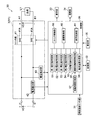
図1は第1の実施の形態を示す電源分配システム内部の概略構成を示すブロック図である。
(Embodiment 1)
FIG. 1 is a block diagram showing a schematic configuration inside the power distribution system according to the first embodiment.
図1において電源分配システム100内の端子台ユニット1は、端子台制御手段2、直流電源装置PSを接続する入力端子I1,I2、直流電源装置PSから供給される直流電圧VDを分岐して負荷L1〜負荷nに、それぞれ直流電圧VDおよび負荷電流IL1〜ILnを供給する出力端子A1,B1〜An,Bnを備える。
In FIG. 1, a
端子台制御手段2は、出力端子A1,B1〜An,Bn(電源供給端子)毎に、複数の負荷(負荷L1〜負荷ln)に供給する直流電源(直流電圧VD)の接続/切断のタイミング、切断電流値を制御するとともに、電流値/電圧値の表示および過電流の通報を制御する。 The terminal block control means 2 connects / disconnects the DC power supply (DC voltage VD) supplied to a plurality of loads (load L1 to load ln) for each of the output terminals A1, B1 to An, Bn (power supply terminals). In addition to controlling the cutting current value, the current value / voltage value display and overcurrent notification are controlled.
図2は第1の実施の形態に関わる端子台制御手段内部の概略構成を示すブロック図である。なお、端子台制御手段2は、出力端子A1,B1から負荷L1に直流電源(直流電圧VD)を供給する1ブロック(チャネルCH1)について説明するが、出力端子A2,B2〜An,Bnから負荷L2〜Lnに直流電源(直流電圧VD)を供給する2ブロック〜nブロック(チャネルCH2〜CHn)についても同じ構成である。
FIG. 2 is a block diagram showing a schematic configuration inside the terminal block control means according to the first embodiment. The terminal block control means 2 will be described with respect to one block (channel CH1) that supplies DC power (DC voltage VD) from the output terminals A1 and B1 to the load L1, but the load from the output terminals A2, B2 to An, and Bn. The same configuration is applied to
図2において、端子台制御手段2は、制御手段3、制御手段3に含まれるシーケンス手段4、電流検出手段5、電圧検出手段6、スイッチング手段7、表示手段8、通報手段9、設定手段10、記憶手段11を備える。 In FIG. 2, the terminal block control means 2 includes control means 3, sequence means 4 included in the control means 3, current detection means 5, voltage detection means 6, switching means 7, display means 8, notification means 9, setting means 10. And storage means 11.
制御手段3は、マイクロプロセッサを基本にA/D変換機能、各種演算機能、比較機能、タイマ機能、処理機能を有し、シーケンス手段4からのタイミング決定された情報に基づいてスイッチデータDSをスイッチング手段7に供給して、スイッチング素子7a,7bをオン/オフさせ、出力ラインLP−出力ラインLM間の直流電圧VDを設定されたタイミングで出力端子A1,B1に接続させたり、切断させたりする。 The control means 3 has an A / D conversion function, various arithmetic functions, a comparison function, a timer function, and a processing function based on a microprocessor, and switches the switch data DS based on the timing-determined information from the sequence means 4. Supplying to the means 7, the switching elements 7a and 7b are turned on / off, and the DC voltage VD between the output line LP and the output line LM is connected to or disconnected from the output terminals A1 and B1 at a set timing. .
また、制御手段3は、電流検出手段5から提供される負荷電流IL1を対応する電圧に変換した変換電圧Vdを記憶手段11に記憶されている電圧値と比較し、変換電圧Vdが過電流IKに対応する電圧値を超えた場合には、通報データDTを供給して、通報手段9から警告音を発生させ、負荷L1に異常電流が流れたことを通知する制御を行う。また、通報データDTに基づいてトランジスタやリレーを動作させて、電気信号を外部に出力し、外部の表示器や警報器に異常電流が流れたこと表示し、通知するようにする制御を行う。 Further, the control means 3 compares the converted voltage Vd obtained by converting the load current IL1 provided from the current detecting means 5 into a corresponding voltage with the voltage value stored in the storage means 11, and the converted voltage Vd is the overcurrent IK. When the voltage value corresponding to is exceeded, notification data DT is supplied, a warning sound is generated from the notification means 9, and control is performed to notify that an abnormal current has flowed to the load L1. In addition, a control is performed to operate a transistor or a relay based on the report data DT, to output an electric signal to the outside, to display and notify that an abnormal current has flowed to an external display or alarm device.
さらに、制御手段3は、電流検出手段5から提供される変換電圧Vdが過電流IKに対応する電圧値をさらにオーバした場合には、スイッチデータDSをスイッチング手段7に供給してスイッチング素子7a,7bをオフさせ、出力ラインLP−出力ラインLM間の直流電圧VDを出力端子A1,B1から切断させる制御を実行する。 Further, when the conversion voltage Vd provided from the current detection means 5 further exceeds the voltage value corresponding to the overcurrent IK, the control means 3 supplies the switch data DS to the switching means 7 to supply the switching elements 7a, 7b is turned off, and control is performed to disconnect the DC voltage VD between the output line LP and the output line LM from the output terminals A1 and B1.
また、制御手段3は、負荷L1に直流電源(直流電圧VD)を供給する初期状態で、電圧検出手段6から提供される検出電圧VPを記憶手段11に記憶されている電圧値と比較し、検出電圧VPが直流電圧VDの定常値(例えば、24V)に近い電圧値(例えば、22V)を越える値が所定時間を越える場合には、スイッチデータDSをスイッチング手段7に供給してスイッチング素子7a,7bをオンさせ、負荷L1を直流電源の初期供給時から正常な電圧で駆動する制御を行う。 The control means 3 compares the detection voltage VP provided from the voltage detection means 6 with the voltage value stored in the storage means 11 in the initial state in which the DC power supply (DC voltage VD) is supplied to the load L1. When the detected voltage VP exceeds a predetermined value (for example, 22V) close to a steady value (for example, 24V) of the DC voltage VD for a predetermined time, the switch data DS is supplied to the switching means 7 to switch the switching element 7a. , 7b are turned on, and the load L1 is controlled to be driven at a normal voltage from the initial supply of DC power.
さらに、制御手段3は、直流電圧VDを負荷L1に供給中に、電圧検出手段6から提供される検出電圧VPが直流電圧VDの定常値(例えば、24V)に近い電圧値(例えば、22V)を下回る値が所定時間を越える場合には、スイッチデータDSをスイッチング手段7に供給してスイッチング素子7a,7bをオフさせ、負荷L1を直流電源の異常な電圧で駆動しない制御を実行する。 Further, while the control means 3 is supplying the DC voltage VD to the load L1, the detection voltage VP provided from the voltage detection means 6 is a voltage value (eg, 22V) close to the steady value (eg, 24V) of the DC voltage VD. When the value less than the predetermined time exceeds the predetermined time, the switch data DS is supplied to the switching means 7 to turn off the switching elements 7a and 7b, and the control not to drive the load L1 with the abnormal voltage of the DC power supply is executed.
また、制御手段3は、電流検出手段5から提供される変換電圧Vdおよび電圧検出手段6から提供される検出電圧VPに基づいて表示データDGを表示手段8に供給し、表示手段8に過電流IKを含む負荷電流IL1および直流電圧VDをそれぞれ電流値および電圧値で表示させる制御を行う。 Further, the control means 3 supplies the display data DG to the display means 8 based on the conversion voltage Vd provided from the current detection means 5 and the detection voltage VP provided from the voltage detection means 6, and the display means 8 is supplied with an overcurrent. Control is performed to display the load current IL1 including IK and the DC voltage VD in terms of current value and voltage value, respectively.
さらに、制御手段3は、設定手段10から供給される直流電源(直流電圧VD)の接続や切断のタイミング情報、過電流IKの複数レベルの過電流値データ、直流電圧VDの供給開始下限電圧データならびに供給停止上限電圧データ、突入電流IRに対する過電流IKの過電流値データおよび継続時間のタイミング情報等の設定情報JSを記憶情報JMとして記憶手段11に格納させる制御を実行する。
Further, the control means 3 connects or disconnects the DC power supply (DC voltage VD) supplied from the setting means 10, overcurrent value data of multiple levels of overcurrent IK, and supply start lower limit voltage data of DC voltage VD. In addition, the
また、制御手段3は、設定手段10からの設定情報JSまたは記憶手段11からの記憶情報JMを表示データDGとして表示手段8に供給し、各種情報およびデータを表示手段8に表示させる制御を行う。
Further, the control unit 3 supplies the setting information JS from the setting
さらに、制御手段3は、負荷L1が容量性負荷のような直流電源(直流電圧VD)を供給する初期状態に突入電流IRが流れる場合、電流検出手段6が過電流過電流IKを検出しても、検出した過電流IKと継続時間τに基づいて過電流IKの通報および電源切断をさせない制御を実行する。 Further, when the inrush current IR flows in the initial state where the load L1 supplies a DC power source (DC voltage VD) such as a capacitive load, the control means 3 detects the overcurrent overcurrent IK. In addition, based on the detected overcurrent IK and the duration τ, the control of not reporting the overcurrent IK and turning off the power is executed.
シーケンス手段4は、順序機能、タイマ機能を備え、設定手段10からの設定情報JSに基づいてスイッチング手段7のスイッチング素子7a,7bをオン/オフさせるスイッチデータDSを発生するタイミングを決定する。 The sequence means 4 has an order function and a timer function, and determines the timing for generating switch data DS for turning on / off the switching elements 7a and 7b of the switching means 7 based on the setting information JS from the setting means 10.
また、シーケンス手段4は、突入電流IRが流れた場合、電流検出手段5から供給される過電流IKの値と継続時間τを監視し、突入電流IRが規定の過電流IKを超えても、規定の継続時間τを下回る場合には、本来ならスイッチング手段7のスイッチング素子7a,7bをオフさせるスイッチデータDSの発生を禁止し、直流電源(直流電圧VD)を負荷L1に継続して供給し、容量性負荷に直流電源(直流電圧VD)を印加する初期状態で必然的に発生する突入電流IRに起因する直流電源(直流電圧VD)の切断を防止する。 Further, when the inrush current IR flows, the sequence means 4 monitors the value of the overcurrent IK supplied from the current detection means 5 and the duration τ, and even if the inrush current IR exceeds the specified overcurrent IK, If it falls below the specified duration τ, the generation of switch data DS that normally turns off the switching elements 7a and 7b of the switching means 7 is prohibited, and a DC power supply (DC voltage VD) is continuously supplied to the load L1. The disconnection of the DC power supply (DC voltage VD) due to the inrush current IR inevitably generated in the initial state of applying the DC power supply (DC voltage VD) to the capacitive load is prevented.
電流検出手段5は、出力ラインLMに挿入した電流検出用抵抗器r、電流検出用抵抗器rに流れる負荷電流IL1による電圧降下を増幅する差動増幅器などで構成し、負荷電流IL1を対応する変換電圧Vdで検出し、変換電圧Vdを制御手段3に提供する。 The current detection means 5 includes a current detection resistor r inserted in the output line LM, a differential amplifier that amplifies a voltage drop due to the load current IL1 flowing through the current detection resistor r, and the like, and corresponds to the load current IL1. Detection is performed by the conversion voltage Vd, and the conversion voltage Vd is provided to the control means 3.
電圧検出手段6は、出力ラインLP−LM間の直流電圧VDを抵抗分割、差動増幅器などで降圧し、降圧した直流電圧VDに対応する検出電圧VPで検出し、検出電圧VPを制御手段3に提供する。 The voltage detection means 6 steps down the DC voltage VD between the output lines LP and LM by resistance division, a differential amplifier or the like, detects the detection voltage VP corresponding to the reduced DC voltage VD, and detects the detection voltage VP by the control means 3. To provide.
スイッチング手段7は、リレーや、MOSFET、トランジスタ等の半導体スイッチで構成して出力ラインLP,LMに挿入し、制御手段3から供給されるスイッチデータDSに基づいてスイッチング素子7aおよびスイッチング素子7bをオン(実線表示)またはオフ(破線表示)に駆動し、直流電源(直流電圧VD)を出力端子A1,B1に接続し、または切断する。 The switching means 7 is composed of a semiconductor switch such as a relay, MOSFET, transistor, etc. and is inserted into the output lines LP, LM, and the switching element 7a and the switching element 7b are turned on based on the switch data DS supplied from the control means 3 It is driven (displayed with a solid line) or off (displayed with a broken line), and a DC power supply (DC voltage VD) is connected to or disconnected from the output terminals A1 and B1.
なお、スイッチング素子7aおよびスイッチング素子7bは、リレー接点、MOSFETのドレインとソース、トランジスタのコレクタとエミッタに相当し、スイッチデータDSをリレー巻線、FETのゲート、トランジスタのベースに供給することにより、リレーや半導体スイッチをオン状態あるいはオフ状態にする。 The switching elements 7a and 7b correspond to relay contacts, MOSFET drains and sources, transistor collectors and emitters, and supply switch data DS to the relay windings, FET gates, and transistor bases. Turn the relay and semiconductor switch on or off.
表示手段8は、表示駆動回路、LCD(液晶表示器)などで構成し、制御手段3から供給される表示データDGに応じて表示駆動信号を発生し、LCDに電流値や電圧値などを表示する。 The display means 8 comprises a display drive circuit, an LCD (liquid crystal display), etc., generates a display drive signal in accordance with the display data DG supplied from the control means 3, and displays a current value, a voltage value, etc. on the LCD. To do.
また、表示手段8は、複数の発光ダイオード(LED)を備え、スイッチング手段7がオン状態にある場合には、例えば青色発光ダイオードLED(B)を点灯し、スイッチング手段7がオフ状態にある場合には、例えば赤色発光ダイオードLED(R)を点灯して表示する。
In addition, the
通報手段9は、発振器、スピーカ、トランジスタ出力やリレー出力等で構成し、制御手段3から供給される通報データDTに応じて警告信号を発生し、例えばスピーカから警告音を発生して直流電圧VDまたは負荷電流IL1の異常を通知する。尚、通報手段9がトランジスタ出力やリレー出力等の場合、制御手段3からの通報データDTに応じて警告信号を発生し、この警告信号を通報出力(表示出力)するものである。 The notification means 9 comprises an oscillator, a speaker, a transistor output, a relay output, etc., and generates a warning signal according to the notification data DT supplied from the control means 3, for example, generates a warning sound from the speaker to generate a DC voltage VD. Alternatively, the abnormality of the load current IL1 is notified. When the reporting means 9 is a transistor output or a relay output, a warning signal is generated according to the reporting data DT from the control means 3, and this warning signal is output (displayed output).
設定手段10は、キー、ボリューム、またはロータリスイッチなどで構成し、直流電源(直流電圧VD)の接続や切断のタイミング情報、過電流IKの複数レベルの過電流値データ、直流電圧VDの供給開始下限電圧データならびに供給停止上限電圧データ、突入電流IRに対する過電流IKの過電流値データ、継続時間のタイミング情報等の設定または変更のための設定情報JSを制御手段3に供給する。 The setting means 10 is constituted by a key, a volume, a rotary switch, or the like, and connection / disconnection timing information of the DC power supply (DC voltage VD), overcurrent value data of multiple levels of overcurrent IK, and supply of DC voltage VD are started. Setting information JS for setting or changing the lower limit voltage data, the supply stop upper limit voltage data, the overcurrent value data of the overcurrent IK relative to the inrush current IR, the timing information of the duration, etc. is supplied to the control means 3.
このように、この発明に係る端子台制御手段2は、電源(直流電圧VD)接続/切断のタイミング、過電流IK値を設定または変更する設定手段10を備えたので、負荷L1に供給する直流電源(直流電圧VD)の電源接続/切断のタイミング、直流電源(直流電圧VD)を切断する過電流IK値の設定または変更を顧客の思いどおりに行うことができ、ユニットの自由度ならびに拡張性を実現することができる。 As described above, the terminal block control means 2 according to the present invention includes the setting means 10 for setting or changing the power source (DC voltage VD) connection / disconnection timing and the overcurrent IK value, and therefore the DC supplied to the load L1. The power supply (DC voltage VD) power supply connection / disconnection timing and overcurrent IK value for cutting off the DC power supply (DC voltage VD) can be set or changed as desired by the customer. Can be realized.
記憶手段11は、ROM等の固定メモリ、フラッシュメモリ等の書替え可能なメモリで構成し、各種制御プログラム、設定手段10からの設定情報JSに基づいて制御手段3の制御により、直流電源(直流電圧VD)の接続や切断のタイミング情報、過電流IKの複数レベルの過電流値データ、直流電圧VDの供給開始下限電圧データならびに供給停止上限電圧データ、突入電流IRに対する過電流IKの過電流値データおよび継続時間のタイミング情報等を記憶情報JMとして記憶(格納)する。 The storage means 11 is composed of a rewritable memory such as a fixed memory such as a ROM or a flash memory, and is controlled by the control means 3 on the basis of various control programs and setting information JS from the setting means 10. VD) connection / disconnection timing information, overcurrent value data of multiple levels of overcurrent IK, supply start lower limit voltage data of DC voltage VD, supply stop upper limit voltage data, overcurrent value data of overcurrent IK relative to inrush current IR In addition, the timing information of the duration is stored (stored) as storage information JM.
また、記憶手段11は、記憶(格納)した記憶情報JMを制御手段3に提供する。
The
このように、この発明に係る端子台制御手段2は、通報を開始する過電流IK値およびスイッチング手段7を切断する過電流IK値の過電流データを記憶するとともに、電源接続/切断のシーケンスデータを記憶する記憶手段11を備えたので、過電流の通報、過電流に対する直流電源の切断、電源接続/切断のシーケンスなどを自由に設定し、実行することができ、利便性をアピールすることができる。 As described above, the terminal block control means 2 according to the present invention stores the overcurrent data of the overcurrent IK value for starting the notification and the overcurrent IK value for disconnecting the switching means 7, and the sequence data of the power supply connection / disconnection. Since the storage means 11 is stored, it is possible to freely set and execute overcurrent notification, DC power supply disconnection, power supply connection / disconnection sequence in response to overcurrent, and appeal convenience. it can.
なお、制御手段3、シーケンス手段4、通報手段9、設定手段10および記憶手段11は、1ブロック(チャネルCH1)に属することで説明したが、2ブロック〜nブロック(チャネルCH2〜CHn)で共用してもよい。 The control means 3, the sequence means 4, the notification means 9, the setting means 10 and the storage means 11 have been described as belonging to one block (channel CH1), but are shared by 2 blocks to n blocks (channels CH2 to CHn). May be.
このように、この発明に係る端子台制御手段2は、電源接続/切断のタイミングを決定するシーケンス手段4、電流(負荷電流IL1)を検出する電流検出手段5、端子電圧(直流電圧VD)を検出する電圧検出手段6、直流電源(直流電圧VD)の接続/切断を実行するスイッチング手段7、電流値/電圧値を表示する表示手段8、過電流IKおよび異常電圧の通報を行う通報手段9、ユニットの全体動作を制御する制御手段3を備えたので、負荷L1に応じて電源接続/切断のタイミングを設定し、運転状態の電流値/電圧値の表示ならびに負荷に過電流が流れたことを通知することができ、使い勝手の良さをアピールすることができる。
As described above, the terminal block control means 2 according to the present invention includes the sequence means 4 for determining the power connection / disconnection timing, the current detection means 5 for detecting the current (load current IL1), and the terminal voltage (DC voltage VD).
図3は第1の実施の形態に関わる制御手段の突入電流防止機能イメージ図である。(a)図は突入電流防止機能がない場合の負荷電流特性、(b)〜(d)図は突入電流防止機能を有する各ブロック(チャネルCH1〜CH3)の時間−負荷電流特性を表わす。なお、1ブロック〜3ブロック(チャネルCH1〜CH3)で、負荷L1〜L3を駆動し、負荷電流IL1〜IL3が流れるものとして説明する。 FIG. 3 is a conceptual diagram of an inrush current preventing function of the control means according to the first embodiment. (A) shows the load current characteristics when there is no inrush current prevention function, and (b) to (d) show the time-load current characteristics of each block (channels CH1 to CH3) having the inrush current prevention function. In the following description, it is assumed that loads L1 to L3 are driven by 1 to 3 blocks (channels CH1 to CH3) and load currents IL1 to IL3 flow.
(a)図において、突入電流防止機能がない状態で、負荷L1〜L3を接続して直流電源装置PSの直流電圧VDを印加した場合、容量性負荷には直流電圧VDの印加時点(時間t=0)で負荷電流ILの波高値が突入電流IRの最大値に達し、容量値と抵抗値の時定数で指数関数的に減少する特性を示す。 (A) In the figure, when the load L1 to L3 is connected and the DC voltage VD of the DC power supply PS is applied without the inrush current prevention function, the application time (time t) of the DC voltage VD is applied to the capacitive load. = 0), the peak value of the load current IL reaches the maximum value of the inrush current IR, and exhibits a characteristic that decreases exponentially with the time constant of the capacitance value and the resistance value.
直流電源装置PSに過電流防止機能があり、突入電流Irが継続時間Tτよりも少ない時間で動作するものとすると、直流電圧VDの印加後の時間Tτで端子台ユニット1への電源供給を停止してしまう。
If the DC power supply PS has an overcurrent prevention function and the inrush current Ir operates in a time shorter than the duration Tτ, the power supply to the
(b)図〜(d)図において、シーケンス手段4を含む制御手段3は、負荷L1〜負荷L3に直流電源(直流電圧VD)を供給開始するタイミングをt1,t2およびt3とし、それぞれ負荷電流IL1の突入電流制限値IR1が継続時間τ、負荷電流IL2の突入電流制限値IR2が継続時間τ、負荷電流IL3の突入電流制限値IR3が継続時間τを越えた場合には、スイッチング手段7のスイッチング素子7aおよびスイッチング素子7bをオフ状態にして負荷L1〜L3への直流電源(直流電圧VD)の供給を停止するように制御手段3が制御すると、負荷電流IL1、負荷電流IL2および負荷電流IL3を停止することなく、負荷L1〜負荷L3に直流電源(直流電圧VD)を継続して供給することができる。 (B) In FIGS. 4 (d) to 4 (d), the control means 3 including the sequence means 4 sets the timings at which the DC power supply (DC voltage VD) starts to be supplied to the loads L1 to L3 as t1, t2 and t3, respectively. When the inrush current limit value IR1 of IL1 is the duration τ, the inrush current limit value IR2 of the load current IL2 is the duration τ, and the inrush current limit value IR3 of the load current IL3 exceeds the duration τ, the switching means 7 When the control means 3 controls the switching element 7a and the switching element 7b to be in an OFF state and stops the supply of the DC power supply (DC voltage VD) to the loads L1 to L3, the load current IL1, the load current IL2, and the load current IL3 The DC power supply (DC voltage VD) can be continuously supplied to the loads L1 to L3 without stopping the operation.
負荷L1〜負荷L3に流す負荷電流IL1〜負荷電流IL3を同時に流さず、負荷電流IL1を流してから負荷電流IL2を流すまで時間Taだけタイミングを遅らせ、負荷電流IL2を流してから負荷電流IL3を流すまで時間Tbだけタイミングを遅らせることにより、負荷電流IL1〜負荷電流IL3の突入電流の波高値を低く抑え、波高値の継続時間も短くすることができ、直流電源装置PSの過電流防止機能を動作させることなく、定常電流が流れる負荷と同様に扱うことができる。 The load current IL1 to the load L3 flowing through the load L1 to the load L3 is not simultaneously flowed, the timing is delayed by the time Ta from the load current IL1 to the flow of the load current IL2, and the load current IL2 is flown before the load current IL3 is flown. By delaying the timing by the time Tb until flowing, the peak value of the inrush current of the load current IL1 to load current IL3 can be suppressed, the duration of the peak value can be shortened, and the overcurrent prevention function of the DC power supply device PS can be achieved. Without operation, it can be handled in the same manner as a load through which a steady current flows.
このように、この発明に係る制御手段3は、電流検出手段5が過電流IKを検出しても、検出した過電流値IKと継続時間τに基づいて過電流の通報および電源切断を実行しないように制御するので、容量性負荷に突入電流IRが流れても、過電流IKの通報および電源切断することなく負荷に電源を供給することができ、信頼性を損なうことなく安定した電源供給を行うことができる。 Thus, even if the current detection means 5 detects the overcurrent IK, the control means 3 according to the present invention does not execute the overcurrent notification and power-off based on the detected overcurrent value IK and the duration τ. Therefore, even if an inrush current IR flows through the capacitive load, it is possible to supply power to the load without reporting the overcurrent IK and turning off the power, and providing stable power supply without losing reliability. It can be carried out.
以上説明したように、この発明に係る端子台ユニット1は、電源装置PSから供給される直流電源(直流電圧VD)を収容し、複数の負荷L1〜Lnに分配して供給する端子台ユニットであって、電源供給端子(出力端子A1,B1〜An,Bn)毎に複数の負荷L1〜Lnに供給する直流電源(直流電圧VD)の接続/切断のタイミング、切断電流値を制御するとともに、電流値/電圧値の表示、過電流および異常電圧の通報を制御する端子台制御手段2を備えたので、負荷に供給する直流電源の状態を顧客が自由に設定し、直流電源の運転状態を一目で確認することができ、使い勝手が良く、利便性の向上を図ることができる。
As described above, the
図4は第1の実施の形態に関わる端子台ユニットの外観構成を示すイメージ図である。なお、端子台ユニット1は、チャネルCH1〜CH3の構成を示し、負荷L1〜L3に直流電源を供給する。
FIG. 4 is an image diagram showing an external configuration of the terminal block unit according to the first embodiment. The
チャネルCH1〜CH3は、それぞれ電圧値および電流値を表示する液晶表示器LCD、負荷電流が正常なことを表示する青色発光ダイオードLED(B)、負荷電流が異常なことを表示する赤色発光ダイオードLED(R)、各種データを設定し、データを選択するための設定/選択つまみVRを備える。 Channels CH1 to CH3 are respectively a liquid crystal display LCD for displaying voltage values and current values, a blue light emitting diode LED (B) for indicating that the load current is normal, and a red light emitting diode LED for indicating that the load current is abnormal. (R) A setting / selection knob VR for setting various data and selecting the data is provided.
スピーカSPは、チャネルCH1〜CH3に共通して警報音を発生する。また、各種データの設定は、パソコン接続コネクタCNを設けて外部パーソナルコンピュータから実行するように構成してもよい。 The speaker SP generates an alarm sound in common with the channels CH1 to CH3. The various data settings may be configured to be executed from an external personal computer by providing a personal computer connection connector CN.
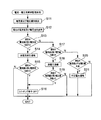
次に、端子台ユニットの制御方法について説明する。図5はこの発明に係る端子台ユニットの制御方法の一実施の形態動作フロー図である。なお、動作フローは、図2を参照して説明する。 Next, a method for controlling the terminal block unit will be described. FIG. 5 is an operation flowchart of one embodiment of the method for controlling the terminal block unit according to the present invention. The operation flow will be described with reference to FIG.
図5において、ステップS1では、直流電源を設定したタイミングで接続する。なお、ステップS1の動作は、シーケンス手段4、制御手段3およびスイッチング手段7が実行する。 In FIG. 5, in step S1, the DC power supply is connected at the set timing. The operation of step S1 is executed by the sequence means 4, the control means 3, and the switching means 7.
ステップS1Aでは、電流値及び電圧値を検出する。尚、ステップS1Aの動作は、電流検出手段5及び電圧検出手段6が実行する。 In step S1A, a current value and a voltage value are detected. The operation of step S1A is executed by the current detection means 5 and the voltage detection means 6.
ステップS2では、電流値および電圧値を表示する。なお、ステップS2の動作は、電流検出手段5、電圧検出手段6、制御手段3および表示手段8が実行する。 In step S2, the current value and the voltage value are displayed. The operation of step S2 is executed by the current detection means 5, the voltage detection means 6, the control means 3, and the display means 8.
ステップS3では、電流値が第1設定値を越えたか否かを判定し、第1設定値を越えた場合にはステップS4に移行する。一方、第1設定値を越えない場合には現在の電流値及び電圧値を検出すべく、ステップS1Aに移行する。なお、ステップS3の動作は、制御手段3が実行する。 In step S3, it is determined whether or not the current value exceeds the first set value. If the current value exceeds the first set value, the process proceeds to step S4. On the other hand, if the first set value is not exceeded, the process proceeds to step S1A to detect the current current value and voltage value. The operation of step S3 is executed by the control means 3.
ステップS4では、過電流を通報する。なお、ステップS4の動作は、制御手段3および通報手段9が実行する。 In step S4, an overcurrent is reported. In addition, the operation | movement of step S4 is performed by the control means 3 and the notification means 9.
ステップS5では、電流値が第2設定値を越えたか否かを判定し、第2設定値を越えた場合にはステップS6に移行する。一方、第2設定値を越えない場合には現在の電流値及び電圧値を検出すべく、ステップS1Aに移行する。なお、ステップS5の動作は、制御手段3が実行する。 In step S5, it is determined whether or not the current value exceeds the second set value. If the current value exceeds the second set value, the process proceeds to step S6. On the other hand, if the second set value is not exceeded, the process proceeds to step S1A to detect the current current value and voltage value. The operation of step S5 is executed by the control means 3.
ステップS6では、電源を切断する。なお、ステップS6の動作は、制御手段3およびスイッチング手段7が実行する。 In step S6, the power is turned off. The operation of step S6 is executed by the control means 3 and the switching means 7.
このように、この発明に係る端子台ユニットの制御方法は、直流電源を設定したタイミングで接続するステップS1と、電流値及び電圧値を検出するステップS1Aと、電流値および電圧値を表示するステップS2と、電流値が第1設定値を越えたか否かを判定するステップS3と、第1設定値を越えた場合に、過電流の通報を実行するステップS4と、電流値が第2設定値を越えたか否かを判定するステップS5と、第2設定値を越えた場合に、電源を切断するステップS6とを備えたので、負荷に過電流が流れたことを通知し、過電流が増加すると直流電源を切断することができ、ユニットの信頼性を向上させることができる。 As described above, the terminal block unit control method according to the present invention includes the step S1 of connecting the DC power supply at the set timing, the step S1A of detecting the current value and the voltage value, and the step of displaying the current value and the voltage value. S2, step S3 for determining whether or not the current value has exceeded the first set value, step S4 for notifying the overcurrent when the current value exceeds the first set value, and the current value being the second set value Step S5 for determining whether or not the current value exceeds the value and Step S6 for cutting off the power supply when the second set value is exceeded, so that the overcurrent flows to the load and the overcurrent increases. Then, the DC power supply can be cut off, and the reliability of the unit can be improved.
(実施の形態2)
次に第2の実施の形態を示す電源分配システムについて説明する。図6は第2の実施の形態を示す電源分配システム内部の概略構成を示すブロック図である。
(Embodiment 2)
Next, a power distribution system showing a second embodiment will be described. FIG. 6 is a block diagram showing a schematic configuration inside the power distribution system showing the second embodiment.
図6に示す電源分配システム20は、直流電力を供給する直流電源装置PSと、この直流電源装置PSと接続し、この直流電源装置PSからの直流電力を複数の負荷L1〜Lnに分配供給する端子台ユニット1Aとで構成している。
A
端子台ユニット1Aは、直流電源装置PSからの直流電力を供給する入力端子I1、I2と、この入力端子I1,I2を通じて直流電力を各負荷L(L1〜Ln)に分岐出力する複数の出力端子A1、B1〜An,Bnと、この端子台ユニット1A全体を制御する端子台制御回路30とを有している。尚、説明の便宜上、端子台ユニット1Aの出力端子A1,B1〜A3,B3の3組として説明する。
The
尚、出力端子A,B(A1,B1〜A3,B3)毎に負荷L(L1〜L3)と接続することで、入力端子I1,I2及び出力端子A,B(A1,B1〜A3,B3)間でCHブロックX(X1〜X3)を構成し、例えば入力端子I1,I2及び出力端子A1,B1間でCHブロックX1を構成し、例えば入力端子I1,I2及び出力端子A3,B3間でCHブロックX3を構成する。 The output terminals A and B (A1, B1 to A3, B3) are connected to the load L (L1 to L3) for each of the output terminals A and B (A1, B1 to A3, B3). ) Between the input terminals I1 and I2 and the output terminals A1 and B1, for example, between the input terminals I1 and I2 and the output terminals A3 and B3. The CH block X3 is configured.
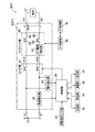
図7は同端子台ユニット1A内の端子台制御回路30内部の概略構成を示すブロック図、図8は同端子台ユニット1Aの外観構成を示すイメージ図である。
FIG. 7 is a block diagram showing a schematic configuration inside the terminal
図7に示す端子台制御回路30は、出力端子A,B(A1,B1〜A3,B3)毎のCHブロックX(X1〜X3)と、端子台ユニット1Aの周囲温度を検出する周囲温度センサ部31と、各種情報を記憶する記憶部32と、各種情報を表示する表示部33と、各種情報を通報出力する通報部34と、記憶部32の記憶内容を変更設定する設定部35と、この端子台制御回路30全体を制御する制御部36とを有している。尚、端子台制御回路30は、複数のCHブロックX1〜X3を収容することになるが、説明の便宜上、CHブロックX1の構成は他のCHブロックX2及びX3の構成と同一になることから、同一符号を付すことで、その重複する構成及び動作の説明については省略する。
The terminal
表示部33は、図8に示すLCD表示部33Aに相当し、後述するCHブロック毎の過電流発生、過電圧発生、不足電圧発生、現在電流値や現在電圧値等を表示すると共に、端子台ユニット1Aの交換時期到来、周囲温度の異常等の各種情報を表示するものである。
The
通報部34は、図8に示すスピーカ34A等に相当し、後述するCHブロック毎の過電流発生、過電圧発生及び不足電圧発生等を警報出力すると共に、端子台ユニット1Aの交換時期到来、周囲温度の異常等の各種情報を警報出力するものである。
The
設定部35は、図8に示す操作部35A及び、PC用接続コネクタ35Bに接続するPC(図示せず)に相当し、記憶部32の記憶内容を設定変更可能とするものである。
The setting
CHブロックX1は、入力端子I1及び出力端子A1間をプラス側ライン、入力端子I2及び出力端子B1間をマイナス側ラインとし、入力端子I1,I2及び出力端子A1,B1間を接続又は切断するスイッチ部41と、入力端子I1,I2及び出力端子A1,B1間の電流を検出する電流検出部42と、入力端子I1,I2及び出力端子A1,B1間の電圧を検出する電圧検出部43とを有している。
The CH block X1 is a switch that connects or disconnects the input terminals I1 and I2 and the output terminals A1 and B1 with the input terminal I1 and the output terminal A1 as a plus line and the input terminal I2 and the output terminal B1 as a minus line.
スイッチ部41は、プラス側ライン及びマイナス側ライン両方に、例えばMOSFET等のスイッチ素子41Aを配置することで構成する。尚、スイッチ部41は、リレー装置等で構成するようにしても良い。
The
記憶部32は、例えば端末台ユニット1Aの周囲温度の異常を判断するための温度に相当する第1周囲温度と、例えば交換時期を判断するための積算稼働時間に相当する第1積算稼働時間と、入力端子I1,I2及び出力端子A1,B1間の過電流発生の有無を判断するための電流値に相当する第1電流値と、入力端子I1,I2及び出力端子A1,B1間のスイッチ部41の接続切断動作を起動するための電流値に相当する第2電流値と、入力端子I1,I2及び出力端子A1,B1間の過電圧発生の有無を判断するための電圧値に相当する第1電圧値と、入力端子I1,I2及び出力端子A1,B1間のスイッチ部41の接続切断動作を起動するための電圧値に相当する第2電圧値と、入力端子I1,I2及び出力端子A1,B1間の不足電圧発生の有無を判断するための電圧値に相当する不足電圧値等とを設定記憶している。尚、第1電流値、第2電流値、第1電圧値及び第2電圧値はCHブロックX(X1〜X3)毎に設定記憶するものである。
The
端末台ユニット1Aのユーザは、設定部35を通じて、記憶部32に記憶中の第1周囲温度、第1積算稼働時間、第1電流値、第2電流値、第1電圧値、第2電圧値及び不足電圧値等を設定変更可能にしている。
The user of the
制御部36は、電流検出部42にて検出した現在の電流値が記憶部32に記憶中の第1電流値を超えたか否かを判定する第1電流値判定部51と、電流検出部42にて検出した現在の電流値が記憶部32に記憶中の第2電流値を超えたか否かを判定する第2電流値判定部52と、電圧検出部43にて検出した現在の電圧値が記憶部32に記憶中の第1電圧値を超えたか否かを判定する第1電圧値判定部53と、電圧検出部43にて検出した現在の電圧値が記憶部32に記憶中の第2電圧値を超えたか否かを判定する第2電圧値判定部54と、電圧検出部43にて検出した現在の電圧値が記憶部32に記憶中の不足電圧値未満であるか否かを判定する不足電圧値判定部55と、周囲温度センサ部31にて検出した現在の周囲温度が第1周囲温度を超えたか否かを判定する周囲温度判定部56と、端末台ユニット1Aの現在の積算稼働時間を計測する稼働時間計測部57と、稼働時間計測部57にて計測した現在の積算稼働時間が記憶部32に記憶中の第1積算稼働時間を経過したか否かを判定する積算稼働時間判定部58と、スイッチ部41を駆動制御するスイッチ制御部59と、通報部34を駆動制御する通報制御部60と、表示部33を表示制御する表示制御部61とを有している。
The
通報制御部60は、第1電流値判定部51にてCHブロックX1の現在の電流値が第1電流値を超えたと判定されると、入力端子I1,I2及び出力端子A1,B1間に過電流が発生したものと判断し、過電流発生に関わる通報信号を通報出力すべく、通報部34を駆動制御するものである。また、同様に、表示制御部61では、過電流発生を表示出力すべく、表示部33を表示制御するものである。
When the first current
また、通報制御部60は、第1電圧値判定部53にてCHブロックX1の現在の電圧値が第1電圧値を超えたと判定されると、入力端子I1,I2及び出力端子A1,B1間に過電圧が発生したものと判断し、過電圧発生に関わる通報信号を通報出力すべく、通報部34を駆動制御するものである。同様に表示制御部61は、過電圧発生を表示出力すべく、表示部33を表示制御するものである。
Further, when the first voltage
また、通報制御部60は、不足電圧値判定部55にてCHブロックX1の現在の電圧値が不足電圧値未満であると判定されると、入力端子I1,I2及び出力端子A1,B1間の電圧値が不足電圧である旨の通報信号を通報出力すべく、通報部34を駆動制御するものである。同様に表示制御部61は、不足電圧発生を表示出力すべく、表示部33を表示制御するものである。
Further, when the undervoltage
また、スイッチ制御部59は、第2電流値判定部52にてCHブロックX1の現在の電流値が第2電流値を超えたと判定されると、入力端子I1,I2及び出力端子A1,B1間の接続を切断するものと判断し、入力端子I1,I2及び出力端子A1,B1間に配置したスイッチ部41の切断動作を実行すべく、スイッチ部41を駆動制御すると共に、第2電圧値判定部54にてCHブロックX1の現在の電圧値が第2電圧値を超えたと判定されると、入力端子I1,I2及び出力端子A1,B1間を切断するものと判断し、入力端子I1,I2及び出力端子A1,B1間に配置したスイッチ部41の切断動作を実行すべく、スイッチ部41を駆動制御するものである。
When the second current value determination unit 52 determines that the current current value of the CH block X1 exceeds the second current value, the
また、制御部36は、電流検出部42にて検出した現在の電流値及び電圧値検出部43にて検出した現在の電圧値を、表示制御部61を通じて表示部33にリアルタイム表示するものである。
The
尚、端子台ユニット1Aの交換時期は、端子台ユニット1Aの負荷率及び周囲温度変化の影響が大である。図9は第2の実施の形態に関わる端子台ユニット1Aの交換時期の関係を示す説明図、図9(a)は寿命期待時間及び周囲温度の関係を示す説明図、図9(b)は寿命期待時間及び負荷率の関係を示す説明図である。
It should be noted that the replacement time of the
アレニウスの法則から明らかなように、図9(a)に示すように、例えば端子台ユニット1Aの周囲温度が10℃高くなると、同端子台ユニット1Aの寿命期待時間は半減、周囲温度が10℃低くなると、同端子台ユニット1Aの寿命期待時間は2倍増えることになる。例えば周囲温度が40℃の一定とし、図9(b)に示すように端子台ユニット1Aの負荷率が高くなると、寿命期待時間は短くなり、負荷率が低くなると、寿命期待時間も長くなる。
As is clear from Arrhenius' law, as shown in FIG. 9A, for example, when the ambient temperature of the
端子台ユニット1Aの負荷率及び周囲温度は端子台ユニット1Aの実際の交換時期(電源寿命時間)を予測する上で大きな目安となる。そこで、本実施の形態においては端子台ユニット1Aの周囲温度変化と、端子台ユニット1Aの周囲温度及び負荷率に対応した期待寿命時間(稼働時間)とに着目し、周囲温度センサ部31及び周囲温度判定部56、稼働時間計測部57及び積算稼働時間判定部58を設けた。
The load factor and the ambient temperature of the
積算稼働時間判定部58は、現在の積算稼働時間が交換時期に相当する第1積算稼働時間を超えたか否かを判定するが、第1積算稼働時間は、図9(b)に示す負荷率及び周囲温度に対応した寿命期待時間を算出し、この算出した寿命期待時間に基づき、自動設定若しくはユーザ設定するものである。
The integrated operating
また、通報制御部60は、積算稼働時間判定部58にて現在の積算稼働時間が交換時期に相当する第1積算稼働時間を超えたと判定されると、例えば交換時期到来の通報信号を通報出力すべく、通報部34を駆動制御するものである。同様に表示制御部61は、交換時期到来を表示出力すべく、表示部33を表示制御するものである。
In addition, when the integrated operation
さらに、通報制御部60は、周囲温度判定部56にて現在の周囲温度が第1周囲温度を超えたと判定されると、周囲温度が異常であると判断し、周囲温度異常の通報信号を通報出力すべく、通報部34を駆動制御するものである。同様に表示制御部61は、周囲温度異常を表示出力すべく、表示部33を表示制御するものである。
Further, when the ambient
尚、本願請求項7記載の電源装置は直流電源装置PS、電源供給端子は出力端子A1,B1〜An,Bn、電流検出手段は電流検出部42、スイッチ手段はスイッチ部41、制御手段は制御部36、本願請求項8記載の記憶手段は記憶部32、第1電流値判定手段は第1電流値判定部51、第2電流値判定手段は第2電流値判定部52、通報出力手段は通報制御部60及び通報部34、スイッチ制御手段はスイッチ制御部59、本願請求項11記載の積算稼働時間監視手段は稼働時間計測部57、積算稼働時間判定手段は積算稼働時間判定部58、本願請求項12記載の周囲温度検出手段は周囲温度センサ部31、周囲温度判定手段は周囲温度判定部56、本願請求項13記載の電圧検出手段は電圧検出部43、第1電圧値判定手段は第1電圧値判定部53、第2電圧値判定手段は第2電圧値判定部54、本願請求項14記載の設定変更手段は設定部35、本願請求項15記載の電流値出力手段は制御部36、表示手段は表示部33に相当するものである。
The power supply device according to claim 7 is a DC power supply PS, power supply terminals are output terminals A1, B1 to An, Bn, current detection means is a
次に第2の実施の形態を示す電源分配システム20の動作について説明する。図10は電流・電圧用異常監視処理に関わる端末台制御回路30内部の制御部36の処理動作を示すフロー図である。
Next, the operation of the
図10に示す電流・電圧用異常監視処理は、CHブロックX(X1〜X3)単位で現在の電流値及び電圧値を監視し、この監視結果に基づき、例えば過電流発生、過電圧発生や不足電圧発生等の異常を通報出力し、場合に応じて入力端子I1,I2及び出力端子A1,B1間の接続を切断するものである。 The current / voltage abnormality monitoring process shown in FIG. 10 monitors the current current value and voltage value in units of CH blocks X (X1 to X3), and based on the monitoring result, for example, overcurrent generation, overvoltage generation or undervoltage. Anomalies such as occurrence are reported and output, and the connection between the input terminals I1 and I2 and the output terminals A1 and B1 is cut according to circumstances.
図10において制御部36は、例えばCHブロックX1内の電流検出部42及び電圧検出部43を通じて入力端子I1,I2及び出力端子A1,B1間のCHブロックX1の現在の電流値及び電圧値を検出すると(ステップS11)、表示制御部61を通じて現在の電流値及び電圧値を表示部33にリアルタイム表示する(ステップS12)。尚、端子台ユニット1Aのユーザは、表示部33に表示中の電流値及び電圧値を見ることでCHブロックX1の現在の運転状況を確認することができる。
In FIG. 10, the
制御部36は、第1電流値判定部51にてCHブロックX1の現在の電流値が第1電流値を超えたか否かを判定する(ステップS13)。
The
制御部36は、第1電流値判定部51にて現在の電流値が第1電流値を超えたと判定されると、入力端子I1,I2及び出力端子A1,B1間に過電流が発生したものと判断し、通報制御部60を通じて過電流発生の通報信号を通報出力すべく、通報部34を駆動制御する(ステップS14)。尚、端子台ユニット1Aのユーザは、通報信号の通報出力に基づき、CHブロックX1での過電流の発生を認識することができる。
When the first current
さらに、制御部36は、過電流発生を通報した後、第2電流値判定部52にてCHブロックX1の現在の電流値が第2電流値を超えたか否かを判定する(ステップS15)。
Further, after reporting the occurrence of overcurrent, the
制御部36は、第2電流値判定部52にて現在の電流値が第2電流値を超えたと判定されると、入力端子I1,I2及び出力端子A1,B1間の接続を切断すべく、スイッチ部41を駆動制御することで(ステップS16)、この処理動作を終了する。尚、スイッチ部41は、スイッチ素子41Aを駆動制御することで、入力端子I1,I2及び出力端子A1,B1間の接続を切断し、CHブロックX1の過電流から負荷L1を保護することができる。
When the second current value determination unit 52 determines that the current current value exceeds the second current value, the
また、制御部36は、ステップS15にて現在の電流値が第2電流値を超えたのでなければ、CHブロックX1の過電流発生の通報出力を継続したまま、この処理動作を終了する。
Further, if the current value does not exceed the second current value in step S15, the
また、制御部36は、ステップS13にて現在の電流値が第1電流値を超えたのでなければ、第1電圧値判定部53にてCHブロックX1の現在の電圧値が第1電圧値を超えたか否かを判定する(ステップS17)。
If the current value does not exceed the first current value in step S13, the
制御部36は、現在の電圧値が第1電圧値を超えたと判定されると、入力端子I1,I2及び出力端子A1,B1間で過電圧が発生したものと判断し、通報制御部60を通じてCHブロックX1での過電圧発生の通報信号を通報出力すべく、通報部34を駆動制御する(ステップS18)。尚、端子台ユニット1Aのユーザは、通報信号の通報出力に基づき、CHブロックX1での過電圧の発生を認識することができる。
When it is determined that the current voltage value exceeds the first voltage value, the
制御部36は、CHブロックX1での過電圧発生を通報した後、第2電圧値判定部54にてCHブロックX1の現在の電圧値が第2電圧値を超えたか否かを判定する(ステップS19)。
After reporting the occurrence of overvoltage in the CH block X1, the
制御部36は、現在の電圧値が第2電圧値を超えたと判定されると、入力端子I1,I2及び出力端子A1,B1間の接続を切断すべく、ステップS16に移行する。尚、スイッチ部41は、スイッチ素子41Aを駆動制御することで、入力端子I1,I2及び出力端子A1,B1間の接続を切断し、CHブロックX1の過電圧から負荷L1を保護することができる。
When it is determined that the current voltage value exceeds the second voltage value, the
また、制御部36は、ステップS19にて現在の電圧値が第2電圧値を超えたのでなければ、過電圧発生の通報を継続したまま、この処理動作を終了する。
If the current voltage value does not exceed the second voltage value in step S19, the
また、制御部36は、ステップS17にて現在の電圧値が第1電圧値を超えたのでなければ、不足電圧値判定部55にてCHブロックX1の現在の電圧値が不足電圧値未満であるか否かを判定する(ステップS20)。
Further, the
制御部36は、現在の電圧値が不足電圧値未満であると判定されると、入力端子I1,I2及び出力端子A1,B1間の不足電圧が発生したものと判断し、通報制御部60を通じて不足電圧発生の通報信号を通報出力すべく、通報部34を駆動制御することで(ステップS21)、この処理動作を終了する。尚、端子台ユニット1Aのユーザは、通報信号の通報出力に基づき、不足電圧の発生を認識することができる。
When it is determined that the current voltage value is less than the undervoltage value, the
制御部36は、現在の電圧値が不足電圧値未満でないと判定されると、CHブロックX1内の入力端子I1,I2及び出力端子A1,B1間が正常運転中であると判断し、この処理動作を終了する。
If it is determined that the current voltage value is not less than the undervoltage value, the
図10に示す電流・電圧用異常監視処理によれば、CHブロックX(X1〜X3)単位で実行し、現在の電流値が第1電流値を超えたと判定されると、過電流の発生を通報出力すると共に、現在の電圧値が第2電圧値を超えたと判定されると、過電圧の発生を通報出力すると共に、現在の電圧値が不足電圧値未満であると判定されると、不足電圧の発生を通報出力するようにしたので、端子台ユニット1Aのユーザは、通報出力に基づき、CHブロック単位で、例えば過電流発生、過電圧発生及び不足電圧の発生等を認識することができる。
According to the current / voltage abnormality monitoring process shown in FIG. 10, when the current current value exceeds the first current value when executed in units of CH blocks X (X1 to X3), an overcurrent is generated. When it is determined that the current voltage value has exceeded the second voltage value, it is output that the occurrence of overvoltage is reported, and when the current voltage value is determined to be less than the undervoltage value, Therefore, the user of the
また、電流・電圧用異常監視処理によれば、現在の電流値が第2電流値を超えたと判定されると、入力端子I1,I2及び出力端子A1,B1間の接続を切断すべく、スイッチ部41を駆動制御すると共に、現在の電圧値が第2電圧値を超えたと判定されると、入力端子I1,I2及び出力端子A1,B1間の接続を切断すべく、スイッチ部41を駆動制御するようにしたので、例えば過電流や過電圧等の異常状況から負荷L1を保護することができる。
Further, according to the current / voltage abnormality monitoring process, when it is determined that the current current value exceeds the second current value, the switch is connected to disconnect the connection between the input terminals I1 and I2 and the output terminals A1 and B1. When the current voltage value exceeds the second voltage value, the
図11は稼働時間・周囲温度監視処理に関わる端子台制御回路30内部の制御部36の処理動作を示すフロー図である。
FIG. 11 is a flowchart showing the processing operation of the
図11に示す稼働時間・周囲温度監視処理は、CHブロックX(X1〜Xn)単位ではなく、端子台ユニット1A単位で積算稼働時間及び周囲温度を監視し、この監視結果に基づき、例えば交換時期の到来や周囲温度の異常等を通報出力する処理である。
In the operation time / ambient temperature monitoring process shown in FIG. 11, the accumulated operation time and the ambient temperature are monitored not in units of CH blocks X (X1 to Xn) but in units of
図11において制御部36は、積算稼働時間計測部57を通じて現在の積算稼働時間を検出すると(ステップS31)、積算稼働時間判定部58にて現在の積算稼働時間が第1積算稼働時間を超えたか否かを判定する(ステップS32)。
In FIG. 11, when the
制御部36は、現在の積算稼働時間が第1積算稼働時間を超えたと判定されると、端子台ユニット1Aの交換時期であると判断し、通報制御部60を通じて交換時期の通報信号を通報出力すべく、通報部34を駆動制御することで(ステップS33)、この処理動作を終了する。尚、端子台ユニット1Aのユーザは、通報信号の通報出力に基づき、端子台ユニット1Aの交換時期到来を認識することができる。
When it is determined that the current accumulated operating time has exceeded the first accumulated operating time, the
制御部36は、ステップS32にて現在の積算稼働時間が第1積算稼働時間を超えていないと判定されると、周囲温度センサ部31を通じて現在の端子台ユニット1Aの周囲温度を検出し(ステップS34)、周囲温度判定部56にて現在の周囲温度が第1周囲温度を超えたか否かを判定する(ステップS35)。
When it is determined in step S32 that the current accumulated operating time does not exceed the first accumulated operating time, the
制御部36は、現在の周囲温度が第1周囲温度を超えたと判定されると、端子台ユニット1Aの周囲温度が異常であると判断し、通報制御部60を通じて周囲温度異常の通報信号を通報出力すべく、通報部34を駆動制御することで(ステップS36)、この処理動作を終了する。尚、端子台ユニット1Aのユーザは、通報信号の通報出力に基づき、端子台ユニット1Aの周囲温度が異常であることを認識することができる。
When it is determined that the current ambient temperature has exceeded the first ambient temperature, the
制御部36は、現在の周囲温度が第1周囲温度を超えたのでなければ、端子台ユニット1Aは正常運転中であると判断し、この処理動作を終了する。
If the current ambient temperature does not exceed the first ambient temperature, the
図11に示す稼働時間・周囲温度監視処理によれば、端子台ユニット1Aの積算稼働時間を監視し、現在の積算稼働時間が第1積算稼働時間を超えたと判定されると、端子台ユニット1Aの交換時期が到来したことを通報出力すると共に、端子台ユニット1Aの周囲温度を監視し、現在の周囲温度が第1周囲温度を超えたと判定されると、端子台ユニット1Aの周囲温度異常を通報出力するようにしたので、端子台ユニット1Aのユーザは、通報出力に基づき、端子台ユニット1Aの交換時期及び周囲温度の異常を認識することができる。
According to the operation time / ambient temperature monitoring process shown in FIG. 11, the integrated operation time of the
第2の実施の形態によれば、CHブロックX(X1〜Xn)単位で実行し、現在の電流値が第1電流値を超えたと判定されると、過電流の発生を通報出力すると共に、現在の電圧値が第2電圧値を超えたと判定されると、過電圧の発生を通報出力すると共に、現在の電圧値が不足電圧値未満であると判定されると、不足電圧の発生を通報出力するようにしたので、端子台ユニット1Aのユーザは、通報出力に基づき、例えば過電流発生、過電圧発生及び不足電圧の発生等を認識することができる。
According to the second embodiment, it is executed in units of CH blocks X (X1 to Xn), and when it is determined that the current current value exceeds the first current value, an overcurrent occurrence is reported and output, When it is determined that the current voltage value exceeds the second voltage value, a notification output of the occurrence of an overvoltage is output, and when it is determined that the current voltage value is less than the undervoltage value, a notification output of the occurrence of the undervoltage is output. Therefore, the user of the
また、第2の実施の形態によれば、現在の電流値が第2電流値を超えたと判定されると、入力端子I1,I2及び出力端子A,B(A1,B1〜An,Bn)間の接続を切断すべく、スイッチ部41を駆動制御すると共に、現在の電圧値が第2電圧値を超えたと判定されると、入力端子I1,I2及び出力端子A,B(A1,B1〜An,Bn)間の接続を切断すべく、スイッチ部41を駆動制御するようにしたので、例えば過電流や過電圧等の異常から負荷L1〜Lnを保護すると共に、その安全性を確保することができる。
Further, according to the second embodiment, when it is determined that the current current value exceeds the second current value, between the input terminals I1 and I2 and the output terminals A and B (A1, B1 to An, Bn). When the current voltage value exceeds the second voltage value, the input terminals I1 and I2 and the output terminals A and B (A1, B1 to An) are controlled. , Bn), the drive of the
また、第2の実施の形態によれば、端子台ユニット1Aの積算稼働時間を監視し、現在の積算稼働時間が第1積算稼働時間を超えたと判定されると、端子台ユニット1Aの交換時期が到来したことを通報出力すると共に、端子台ユニット1Aの周囲温度を監視し、現在の周囲温度が第1周囲温度を超えたと判定されると、端子台ユニット1Aの周囲温度異常を通報出力するようにしたので、端子台ユニット1Aのユーザは、通報出力に基づき、端子台ユニット1Aの交換時期及び周囲温度の異常を認識することができる。
In addition, according to the second embodiment, the accumulated operation time of the
尚、上記第2の実施の形態においては、現在の電流値が第1電流値や第2電流値を超えたか否かを判定するステップS13及びステップS15の判断処理(現在の電圧値が第1電圧値及び第2電圧値を超えたか否かを判定するステップS17及びステップS19の判断処理)があるが、電流値(電圧値)は瞬間的に乱高下する場合も考えられるため、同判断処理を現在の電流値(電圧値)が第1電流値(第1電圧値)や第2電流値(第2電圧値)を所定時間以上継続して超えたと判定された場合にのみ、現在の電流値(電圧値)を第1電流値(第1電圧値)や第2電流値(第2電圧値)を超えたものと判断するようにしても良く、この場合、電流値(電圧値)が乱高下して瞬間的に第1電流値(第1電圧値)若しくは第2電流値(第2電圧値)を超えたことで過電流(過電圧)と判断してしまうような誤動作を確実に防止することで信頼性を損なうことなく安定した電力供給を確保することができる。 In the second embodiment, the determination process of step S13 and step S15 for determining whether the current current value exceeds the first current value or the second current value (the current voltage value is the first voltage value). There is a determination process of step S17 and step S19 for determining whether or not the voltage value and the second voltage value are exceeded, but the current value (voltage value) may be instantaneously fluctuated. Only when it is determined that the current value (voltage value) has exceeded the first current value (first voltage value) or the second current value (second voltage value) for a predetermined time or longer, the current value is It may be determined that the (voltage value) exceeds the first current value (first voltage value) or the second current value (second voltage value). In this case, the current value (voltage value) is unstable. The first current value (first voltage value) or the second current value (second voltage value) It is possible to secure a stable power supply without sacrificing reliability by reliably prevent erroneous operation that would determine the overcurrent (overvoltage) by exceeded.
また、上記第2の実施の形態においては、CHブロックX1のスイッチ部41内のスイッチング素子41Aを入力端子I1及び出力端子A1間のマイナス側ライン、及び入力端子I2及び出力端子B1間のプラス側ライン両方に夫々配置するようにしたが、マイナス側ライン又はプラス側ラインのどちらか一方にのみスイッチング素子41Aを配置するようにしても良く、この場合、スイッチング素子41Aの数を減らしながら、同様の効果が得られることはいうまでもない。
In the second embodiment, the switching
また、上記第2の実施の形態においては、端子台ユニット1Aの周囲温度が第1周囲温度を超えたと判定されると、周囲温度の異常を通報出力するようにしたが、同通報出力に基づき、例えば端子台ユニット1Aの周囲温度を下げる冷却ファーン部を駆動制御するようにしても良く、この場合は自動的に端子台ユニット1Aの周囲温度を下げることができる。
Further, in the second embodiment, when it is determined that the ambient temperature of the
また、上記第2の実施の形態においては、CHブロックX(X1〜Xn)単位で現在の電流値及び電圧値を表示部33にリアルタイムに表示するようにしたが、例えば所定時間単位の電流平均値、ピーク電流値や低電流値を表示部33に表示するようにしても良く、例えば電流平均値を表示した場合、電流変化による負荷L1〜Lnの異常をユーザ側で予測することができ、また、ピーク電流値を表示した場合、異常時の原因追求に役立ち、また、低電流値を表示した場合、例えば断線の予測が可能となる。
In the second embodiment, the current value and voltage value are displayed in real time on the
また、上記第2の実施の形態においては、単一の直流電源装置PSと単一の端子台ユニット1Aとを直列に接続する電源分配システム20を例に挙げて説明したが、例えば単一の直流電源装置PSと複数の端子台ユニット1Aを並列に接続し、直流電源装置PSから各端子台ユニットに電力を供給する電源分配システムであっても同様の効果が得られることは言うまでもない。
In the second embodiment, the
また、上記第2の実施の形態においては、現在の電流値が第2電流値を超えたと判定されると、又は現在の電圧値が第2電圧値を超えたと判定されると、入力端子I1,I2及び出力端子A,B(A1,B1〜An,Bn)の接続を切断すべく、スイッチ部41を駆動制御するようにしたが、例えば設定部35からの切断操作を検出すると、入力端子I1,I2及び出力端子A,B(A1,B1〜An,Bn)間の接続を切断すべく、スイッチ部41を駆動制御するようにしても良く、この場合、端子台ユニット1Aのユーザの操作で入力端子I1,I2及び出力端子A,B(A1,B1〜An,Bn)間の接続を切断することができる。
In the second embodiment, when it is determined that the current current value exceeds the second current value, or when it is determined that the current voltage value exceeds the second voltage value, the input terminal I1. , I2 and the output terminals A and B (A1, B1 to An, Bn) are controlled to drive the
また、上記第2の実施の形態においては、端子台ユニット1AはCHブロックX単位で単一の負荷Lに接続して同負荷Lに対して直流電源装置PSからの電力を分岐出力するようにしたが、例えば単一の負荷L1に対して複数のCHブロックの出力端子、例えばCHブロックX1の出力端子A1,B1及びCHブロックX2の出力端子A2,B2と接続して同負荷L1に対してCHブロックX1及びX2からの電力を供給するようにしても同様の効果が得られることは言うまでもない。
In the second embodiment, the
また、上記第2の実施の形態においては、ブロックX単位で入力端子I1,I2及び出力端子A1,B1(A2,B2〜An,Bn)間にスイッチ部41を配置し、制御部36は、現在の電流値及び電圧値の監視結果に基づき、スイッチ制御部59を通じてスイッチ部41を駆動制御することで、入力端子I1,I2及び出力端子A1,B1(A2,B2〜An,Bn)間の接続を切断するようにしたが、何等かの要因で制御部36が故障してしまった場合、入力端子I1,I2及び出力端子A1,B1(A2,B2〜An,Bn)間の接続を切断することができないと言った事態も考えられる。
In the second embodiment, the
(実施の形態3)
そこで、このような事態を対処すべく、第3の実施の形態を示す電源分配システム20Aについて説明する。尚、第2の実施の形態を示す電源分配システム20と同一の構成には同一符号を付すことで、その重複する構成及び動作の説明については省略する。
(Embodiment 3)
Therefore, in order to cope with such a situation, a power distribution system 20A showing a third embodiment will be described. The same components as those of the
図12は第3の実施の形態に関わる端子台制御回路30A内部の概略構成を示すブロック図である。
FIG. 12 is a block diagram showing a schematic configuration inside the terminal
図12に示す端子台制御回路30Aと図7に示す端子台制御回路30とが異なるところは、CHブロックX1内のスイッチ部41の後段に配置されたサブスイッチ部80と、このサブスイッチ部80を駆動制御するサブ制御部90とを備えた点にある。
The terminal
サブスイッチ部80は、入力端子I1,I2及び出力端子A1,B1間の電流を検出するサブ電流検出部81と、入力端子I1,I2及び出力端子A1,B1間の接続を切断するサブスイッチ素子82及びヒューズ83とを有している。
The
サブ制御部90は、制御部36から独立し、サブスイッチ部80を駆動制御するものであって、サブ電流検出部81にて入力端子I1,I2及び出力端子A1,B1間の現在の電流値を検出すると、現在の電流値がサブ記憶部91に記憶中の第3電流値を超えたか否かを判定し、現在の電流値が第3電流値を超えたと判定されると、入力端子I1,I2及び出力端子A1,B1間の接続を切断すべく、サブスイッチ部80内のサブスイッチ素子82を駆動制御するものである。尚、サブ記憶部91に記憶中の第3電流値は、前述した第2電流値以上にすることが望ましく、例えばClass2規格を満たした出力電流値4.167A(出力電圧が24Vのとき、100VA/24V=4.167Aより)にすることが望ましい。
The
尚、本願請求項10記載のサブスイッチ手段はサブスイッチ部80、サブ記憶手段はサブ記憶部91、第3電流値判定手段及びサブ制御手段はサブ制御部90に相当するものである。
The sub-switch means described in
制御部36が正常に動作中の場合、入力端子I1,I2及び出力端子A1,B1間の現在の電流値が第2電流値を超えると、入力端子I1,I2及び出力端子A1,B1間の接続を切断すべく、スイッチ部41のスイッチ素子41Aを駆動制御することになる。つまり、制御部36が正常に動作中の場合、制御部36及びサブ制御部80双方が独立して現在の電流値の判断処理を実行するものである。
When the
従って、サブ制御部90は、制御部36が何等かの原因で故障したとしても、入力端子I1,I2及び出力端子A1,B1間の現在の電流値が第3電流値を超えたか否かを判定し、現在の電流値が第3電流値を超えた場合、入力端子I1,I2及び出力端子A1,B1間の接続を切断すべく、サブスイッチ部80内のサブスイッチ素子82を駆動制御することになる。
Therefore, the
また、制御部36及びサブ制御部90が故障したとしても、異常な出力電流が流れると、サブスイッチ素子82後段のヒューズにて入力端子I1,I2及び出力端子A1,B1間の接続を切断するものである。
Further, even if the
第3実施の形態によれば、制御部36から独立してサブ制御部90にて現在の電流値が第3電流値を超えた場合、入力端子I1,I2及び出力端子A1,B1間の接続を切断すべく、サブスイッチ部80内のサブスイッチ素子82を駆動制御するようにしたので、制御部36が故障したとしても、異常な出力電流が負荷に流れ込まないように、安全かつ確実に過電流から負荷を保護することができる。
According to the third embodiment, when the current value exceeds the third current value in the
第3の実施の形態によれば、サブスイッチ素子82の後段にヒューズ83を配置したので、制御部36及びサブ制御部90を故障したとしても、異常な出力電流が流れると、ヒューズ83が切断されるため、異常な出力電流が負荷に流れ込むことはない。
According to the third embodiment, since the
尚、上記第3の実施の形態においては、現在の電流値が第3電流値を超えたと判定されると、入力端子I1,I2及び出力端子A1,B1間の接続を切断すべく、サブスイッチ素子82を駆動制御するようにしたが、電流値は瞬間的に乱高下する場合も考えられるため、現在の電流値が第3電流値を所定時間以上継続して超えたと判定された場合にのみ、現在の電流値が第3電流値を超えたものと判断するようにしても良く、この場合、例えば電流値が乱高下して瞬間的に第3電流値を超えたことでサブスイッチ素子82を駆動制御してしまうような誤動作を確実に防止することで信頼性を損なうことなく安定した電力供給を確保することができる。
In the third embodiment, when it is determined that the current value exceeds the third current value, the sub switch is used to disconnect the connection between the input terminals I1 and I2 and the output terminals A1 and B1. The
上記第3の実施の形態においては、電流値を監視対象とし、現在の電流値が第3電流値を超えたと判定されると、入力端子I1,I2及び出力端子A1,B1間の接続を切断すべく、サブスイッチ素子82を駆動制御するようにしたが、電圧値を監視対象とし、現在の電圧値が第2電圧値以上の第3電圧値を超えたか否かを判定し、現在の電圧値が第3電圧値を超えたと判定されると、入力端子I1,I2及び出力端子A1,B1間の接続を切断すべく、サブスイッチ素子82を駆動制御するようにしても良く、この場合、制御部36が故障したとしても、異常な出力電圧から負荷L1を保護することができる。
In the third embodiment, the current value is monitored, and when it is determined that the current current value exceeds the third current value, the connection between the input terminals I1 and I2 and the output terminals A1 and B1 is disconnected. Therefore, the
また、上記第2の実施の形態及び第3の実施の形態においては、スイッチ素子41A及びサブスイッチ素子82としてMOSFETを例に挙げて説明したが、MOSFETのコストを考えると、許容電流には制限があるため、CHブロックXと接続する単一の負荷Lに供給する電流容量にも制限が出てくる。そこで、複数のCHブロックX経由で単一の負荷Lに電流を供給できるようにしても良いことは言うまでもない。
In the second embodiment and the third embodiment, the MOSFET is described as an example of the
また、上記第2の実施の形態及び第3の実施の形態においては、図9(b)に示す負荷率及び周囲温度に対応した寿命期待時間を算出し、この算出した寿命期待時間に基づき、積算稼働時間判定部58の第1積算稼働時間を自動設定若しくはユーザ設定するようにしたが、次に説明するように第1積算稼働時間を算出するようにしても良い。
Further, in the second embodiment and the third embodiment, the expected life time corresponding to the load factor and the ambient temperature shown in FIG. 9B is calculated, and based on the calculated expected life time, Although the first integrated operating time of the integrated operating
第1の算出方法としては、ある周期毎に端子台ユニット1Aの平均使用温度を演算してメモリデータの更新動作を実行する。具体的にはメモリデータ更新回数(n)、データ更新時の読取温度(T[n])及び前回の平均使用温度(Tave[n−1])を数式1に当てはめ、現在までの平均使用温度(Tave[n])を算出する。
As a first calculation method, an average operation temperature of the
(数1)
Tave[n]=Tave[n−1]+(1/n)*{T[n]−Tave[n−1]}(数式1)
さらにTave[n]と周囲温度40℃との差、初期設定時間(40℃時の製品の期待寿命)L0及びアレニウムの法則を用いて数式2に当てはめ、交換時期の目安時間(第1積算稼働時間)L[n]を算出する。
(Equation 1)
Tave [n] = Tave [n−1] + (1 / n) * {T [n] −Tave [n−1]} (Formula 1)
Furthermore, the difference between Tave [n] and ambient temperature 40 ° C, initial setting time (expected product life at 40 ° C) L0 and Allen's law are applied to
(数2)
L[n]=L0*2^{(40−Tave[n])/10}(数式2)
従って、第1の算出方法によれば、端子台ユニット1Aの負荷変動は周囲温度変動と比較しても小さいことから、周囲温度のみを考慮して第1積算稼働時間を算出することができる。
(Equation 2)
L [n] = L0 * 2 ^ {(40−Tave [n]) / 10} (Formula 2)
Therefore, according to the first calculation method, since the load fluctuation of the
尚、第1の算出方法は、端子台ユニット1Aの負荷電流が大きく変動しない場合を条件として説明したが、正確な第1積算稼働時間を算出するためには負荷変動も加味する必要がある。
The first calculation method has been described on the condition that the load current of the
そこで、第2の算出方法としては、図13(a)に示すように出力電流が変動すると、この変動に応じて内部発熱量も変動することに着目し、例えば初期設定時の出力電流に対して出力電流が増加してΔT1の内部発熱量が発生したとすると、数式3に当てはめることで、現在の平均使用温度(Tave[n])を算出することができる。 Therefore, as a second calculation method, paying attention to the fact that when the output current fluctuates as shown in FIG. 13A, the internal heat generation amount fluctuates in accordance with this fluctuation, for example, with respect to the output current at the initial setting, If the output current increases and an internal heat generation amount ΔT1 is generated, the current average operating temperature (Tave [n]) can be calculated by applying Equation 3.
(数3)
Tave[n]=Tave[n−1]+(1/n)*{T[n]−Tave[n−1]+ΔT1}(数式3)
そして、この現在の平均使用温度(Tave[n])を数式2に当てはめることで、交換時期の目安時間(第1積算稼働時間)L[n]を算出する。
(Equation 3)
Tave [n] = Tave [n−1] + (1 / n) * {T [n] −Tave [n−1] + ΔT1} (Formula 3)
Then, by applying this current average use temperature (Tave [n]) to
従って、第2の算出方法によれば、端子台ユニット1Aの周囲温度変動の他に負荷変動を加味することで、正確な第1積算稼働時間を算出することができる。
Therefore, according to the second calculation method, the accurate first integrated operation time can be calculated by taking into account the load fluctuation in addition to the ambient temperature fluctuation of the
さらに正確に第1積算稼働時間を算出する第3の算出方法としては、端子台ユニット1A内の電解コンデンサに流れるリップル電流Iiも考慮し、図13(b)に示すように出力電流が変動すると、この変動に応じて電解コンデンサに流れるリップル電流Iiも変動することに着目し、電解コンデンサ固有の電流I0及び発熱量T0、初期設定時のリップル電流Iiを数式4に当てはめることで、初期設定時のリップル電流Iiによる発熱量ΔTiを算出する。
As a third calculation method for calculating the first integrated operation time more accurately, the ripple current Ii flowing through the electrolytic capacitor in the
(数4)
ΔTi=(Ii/Io)2*T0(数式4)
次に電解コンデンサ固有の電流I0及び発熱量T0、現在のリップル電流Iを数式5に当てはめることで、現在のリップル電流Iによる発熱量ΔTを算出する。
(Equation 4)
ΔTi = (Ii / Io) 2 * T0 (Formula 4)
Next, the heat generation amount ΔT due to the current ripple current I is calculated by applying the current I0 and the heat generation amount T0 specific to the electrolytic capacitor and the current ripple current I to Equation 5.
(数5)
ΔT=(I/Io)2*T0(数式5)
さらに前回のリップル電流による発熱平均値ΔTave[n−1]を数式6に当てはめることで、リップル電流による発熱平均値ΔTave[n]を算出する。
(Equation 5)
ΔT = (I / Io) 2 * T0 (Formula 5)
Furthermore, the heat generation average value ΔTave [n] due to the ripple current is calculated by applying the heat generation average value ΔTave [n−1] due to the previous ripple current to
(数6)
ΔTave[n]=ΔTave[n−1]+(1/n)*{ΔT[n]−ΔTave[n−1](数式6)
そして、Tave[n]と周囲温度40℃との差、初期設定時間(40℃時の製品の期待寿命)L0、初期設定時のリップル電流による発熱量ΔT、リップル電流による発熱平均値ΔTave[n]及びアレニウムの法則を用いて数式7に当てはめ、交換時期の目安時間(第1積算稼働時間)L[n]を算出する。
(Equation 6)
ΔTave [n] = ΔTave [n−1] + (1 / n) * {ΔT [n] −ΔTave [n−1] (Formula 6)
Then, the difference between Tave [n] and ambient temperature 40 ° C., initial setting time (expected product life at 40 ° C.)
(数7)
L[n]=L0*2^{(40−Tave[n])/10}*2^{(ΔTi−ΔTave[n])/5}(数式7)
従って、第3の算出方法によれば、端子台ユニット1Aの周囲温度変動及び負荷変動の他に電解コンデンサのリップル電流の変動を加味することで、第2の算出方法に比較しても、より正確な第1積算稼働時間を算出することができる。
(Equation 7)
L [n] = L0 * 2 ^ {(40−Tave [n]) / 10} * 2 ^ {(ΔTi−ΔTave [n]) / 5} (Formula 7)
Therefore, according to the third calculation method, by adding the fluctuation of the ripple current of the electrolytic capacitor in addition to the ambient temperature fluctuation and the load fluctuation of the
尚、上記第1乃至第3の算出方法によれば、交換時期の目安時間となる第1積算稼働時間を算出するようにしたが、この第1積算稼働時間を利用して、第1積算稼働時間から現在までの積算稼働時間を減算することで、交換時期までの残り時間を表示部33に画面表示するようにしても良いことは言うまでもない。
Note that, according to the first to third calculation methods, the first integrated operation time, which is the reference time for the replacement time, is calculated. The first integrated operation time is used to calculate the first integrated operation time. It goes without saying that the remaining time until the replacement time may be displayed on the
本発明の端子台ユニットは、電源供給端子毎に直流電源の接続/切断のタイミング、直流電源を切断する過電流の設定および実行が可能で、電流値/電圧値の表示および過電流の通報ができ、電源装置から供給される直流電源を収容し、複数の負荷に分配して供給するあらゆる端子台ユニットに適用することができる。 The terminal block unit of the present invention can set and execute the timing of connecting / disconnecting the DC power supply for each power supply terminal, the overcurrent for disconnecting the DC power supply, displaying the current value / voltage value and reporting the overcurrent. It can be applied to any terminal block unit that accommodates DC power supplied from a power supply device and distributes and supplies it to a plurality of loads.
また、本発明の端子台ユニットは、電源供給端子毎に同電源供給端子経由の電源装置及び電源供給端子間の電流を検出し、現在の電流値に基づき、電流情報に関わる通報信号を出力すると共に、電源装置及び電源供給端子間のスイッチ手段の接続切断動作を実行するようにしたので、例えば負荷に過電流が流れたことを通知することができると共に、負荷に過電流が流れたとしても、自動的に電源装置及び電源供給端子間の接続を切断することで安全性を確保することができるため、例えば工場等の様々な生産ラインに使用される端子台ユニットに有用である。 Further, the terminal block unit of the present invention detects the current between the power supply device and the power supply terminal via the power supply terminal for each power supply terminal, and outputs a notification signal related to current information based on the current value. At the same time, since the disconnection operation of the switch means between the power supply device and the power supply terminal is executed, for example, it can be notified that an overcurrent has flowed to the load, and even if an overcurrent has flowed to the load Since the safety can be ensured by automatically disconnecting the connection between the power supply device and the power supply terminal, it is useful for a terminal block unit used in various production lines such as factories.
1 端子台ユニット
1A 端子台ユニット
2 端子台制御手段
3 制御手段
4 シーケンス手段
5 電流検出手段
6 電圧検出手段
7 スイッチング手段
8 表示手段
9 通報手段
10 設定手段
11 記憶手段
31 周囲温度センサ部(周囲温度検出手段)
32 記憶部(記憶手段)
33 表示部(表示手段)
34 通報部(通報出力手段)
35 設定部(設定変更手段)
36 制御部(制御手段、電流値出力手段)
41 スイッチ部(スイッチ手段)
42 電流検出部(電流検出手段)
43 電圧検出部(電圧検出手段)
51 第1電流値判定部(第1電流値判定手段)
52 第2電流値判定部(第2電流値判定手段)
53 第1電圧値判定部(第1電圧値判定手段)
54 第2電圧値判定部(第2電圧値判定手段)
56 周囲温度判定部(周囲温度判定手段)
57 稼働時間計測部(積算稼働時間監視手段)
58 積算稼働時間判定部(積算稼働時間判定手段)
59 スイッチ制御部(スイッチ制御手段)
60 通報制御部(通報出力手段)
PS 直流電源装置(電源装置)
A1,B1〜An,Bn 出力端子(電源供給端子)
1
32 storage unit (storage means)
33 Display section (display means)
34 Report Department (Report output means)
35 Setting section (setting change means)
36 Control part (control means, current value output means)
41 Switch part (switch means)
42 Current detection unit (current detection means)
43 Voltage detector (voltage detection means)
51 1st electric current value determination part (1st electric current value determination means)
52 Second current value determination unit (second current value determination means)
53 1st voltage value determination part (1st voltage value determination means)
54 2nd voltage value determination part (2nd voltage value determination means)
56 Ambient temperature judgment unit (Ambient temperature judgment means)
57 Operating time measuring unit (Integrated operating time monitoring means)
58 Integrated operating time determination unit (Integrated operating time determination means)
59 Switch control unit (switch control means)
60 Report control unit (report output means)
PS DC power supply (power supply)
A1, B1-An, Bn Output terminal (power supply terminal)
Claims (15)
電源供給端子毎に前記複数の負荷に供給する直流電源の接続/切断のタイミング、切断電流値を制御するとともに、電流値/電圧値の表示、過電流および異常電圧の通報を制御する端子台制御手段を備えたことを特徴とする端子台ユニット。 A terminal block unit that accommodates DC power supplied from a power supply and distributes and supplies it to a plurality of loads.
Terminal block control for controlling the connection / disconnection timing and disconnection current value of DC power supplied to the plurality of loads for each power supply terminal, as well as displaying the current value / voltage value, reporting overcurrent and abnormal voltage A terminal block unit comprising means.
直流電源を設定したタイミングで接続するステップS1と、
電流値および電圧値を表示するステップS2と、
電流値が第1設定値を越えたか否かを判定するステップS3と、
第1設定値を越えた場合に、過電流の通報を実行するステップS4と、
電流値が第2設定値を越えたか否かを判定するステップS5と、
第2設定値を越えた場合に、電源を切断するステップS6と、
を備えたことを特徴とする端子台ユニットの制御方法。 A method for controlling a terminal block unit that accommodates DC power supplied from a power supply and distributes and supplies the power to a plurality of loads.
Step S1 for connecting the DC power supply at a set timing;
Step S2 for displaying the current value and the voltage value;
Step S3 for determining whether or not the current value exceeds the first set value;
Step S4 for executing an overcurrent notification when the first set value is exceeded;
Step S5 for determining whether or not the current value exceeds the second set value;
Step S6 for turning off the power when the second set value is exceeded;
A terminal block unit control method comprising:
前記電源供給端子毎に設け、前記電源装置及び電源供給端子間の電流を検出する電流検出手段と、
前記電源供給端子毎に設け、前記電源装置及び電源供給端子間の接続を切断するスイッチ手段と、
前記電流検出手段にて検出した現在の電流値に基づき、電流情報に関わる通報信号を出力すると共に、前記スイッチ手段の接続切断動作を実行すべく、前記スイッチ手段を制御する制御手段とを有することを特徴とする端子台ユニット。 A terminal block unit having a plurality of power supply terminals for connecting to a power supply and distributing and supplying power from the power supply to a plurality of loads,
A current detecting means provided for each power supply terminal, for detecting a current between the power supply device and the power supply terminal;
Switch means provided for each of the power supply terminals, and disconnecting the connection between the power supply device and the power supply terminals;
Based on the current value detected by the current detection means, a reporting signal related to current information is output, and control means for controlling the switch means to execute a disconnection operation of the switch means Terminal block unit characterized by
前記制御手段は、
前記電流検出手段にて検出した現在の電流値が前記第1電流値を超えたか否かを判定する第1電流値判定手段と、
前記電流検出手段にて検出した現在の電流値が前記第2電流値を超えたか否かを判定する第2電流値判定手段と、
前記第1電流値判定手段にて前記電流値が前記第1電流値を超えたと判定されると、過電流発生に関わる電流情報の通報信号を出力する通報出力手段と、
前記第2電流値判定手段にて前記電流値が前記第2電流値を超えたと判定されると、前記スイッチ手段の接続切断動作を実行すべく、前記スイッチ手段を制御するスイッチ制御手段とを有することを特徴とする請求項7記載の端子台ユニット。 Storage means for storing a first current value for determining occurrence of an overcurrent and a second current value for starting a connection disconnection operation of the switch means;
The control means includes
First current value determination means for determining whether or not the current current value detected by the current detection means exceeds the first current value;
Second current value determination means for determining whether or not a current value detected by the current detection means exceeds the second current value;
When the first current value determination means determines that the current value has exceeded the first current value, a notification output means for outputting a notification signal of current information related to the occurrence of overcurrent;
Switch means for controlling the switch means to perform a disconnection operation of the switch means when the second current value judgment means determines that the current value has exceeded the second current value; The terminal block unit according to claim 7.
前記第1電流値判定手段にて前記電流値が前記第1電流値を所定継続時間以上継続して超えたと判定されると、前記過電流発生に関わる電流情報の通報信号を出力すると共に、
前記第1電流値判定手段にて前記電流値が前記第1電流値を前記所定継続時間以上継続して超えてないと判定されると、前記通報信号の出力を禁止すると共に、
前記スイッチ制御手段は、
前記第2電流値判定手段にて前記電流値が前記第2電流値を前記所定継続時間以上継続して超えたと判定されると、前記スイッチ手段の接続切断動作を実行すべく、前記スイッチ手段を制御すると共に、
前記第2電流値判定手段にて前記電流値が前記第2電流値を前記所定継続時間以上継続して超えていないと判定されると、前記スイッチ手段の接続切断動作を禁止すべく、前記スイッチ手段を制御することを特徴とする請求項8記載の端子台ユニット。 The notification output means includes
When it is determined by the first current value determination means that the current value has continuously exceeded the first current value for a predetermined duration or more, a report signal of current information related to the occurrence of the overcurrent is output,
When it is determined by the first current value determination means that the current value does not continuously exceed the first current value for the predetermined duration or longer, the output of the notification signal is prohibited,
The switch control means includes
When it is determined by the second current value determination means that the current value has continuously exceeded the second current value for the predetermined duration or longer, the switch means is used to perform the disconnection operation of the switch means. Control and
When the second current value determining means determines that the current value does not continuously exceed the second current value for the predetermined duration or longer, the switch means is configured to prohibit the disconnection operation of the switch means. 9. The terminal block unit according to claim 8, wherein the means is controlled.
前記第2電流値以上の電流値に相当する第3電流値を記憶するサブ記憶手段と、
前記電源装置及び電源供給端子間の現在の電流値が前記第3電流値を超えたか否かを判定する第3電流値判定手段と、
この第3電流値判定手段にて前記電流値が前記第3電流値を超えたと判定されると、前記サブスイッチ手段の接続切断動作を実行すべく、前記サブスイッチ手段を制御するサブ制御手段とを有することを特徴とする請求項8又は9記載の端子台ユニット。 A sub-switch means disposed at a subsequent stage of the switch means for cutting off the connection between the power supply device and the power supply terminal;
Sub-storage means for storing a third current value corresponding to a current value equal to or greater than the second current value;
Third current value determination means for determining whether or not a current current value between the power supply device and the power supply terminal exceeds the third current value;
A sub-control unit that controls the sub-switch unit to perform a disconnection operation of the sub-switch unit when the third current-value determining unit determines that the current value has exceeded the third current value; The terminal block unit according to claim 8 or 9, characterized by comprising:
現在の積算稼動時間を監視する積算稼働時間監視手段と、
前記積算稼動時間監視手段にて現在の積算稼動時間が前記第1積算稼動時間を超えたか否かを判定する積算稼働時間判定手段とを有し、
前記通報出力手段は、
前記積算稼働時間判定手段にて現在の積算稼働時間が前記第1積算稼働時間を超えたと判定されると、前記積算稼働時間に関わる情報の通報信号を出力することを特徴とする請求項8,9又は10記載の端子台ユニット。 The storage means for storing a first integrated operating time corresponding to a predetermined integrated operating time;
An integrated operating time monitoring means for monitoring the current integrated operating time;
Integrated operating time determination means for determining whether or not the current integrated operating time exceeds the first integrated operating time in the integrated operating time monitoring means;
The notification output means includes
9. The information signal relating to the integrated operation time is output when the integrated operation time determination unit determines that the current integrated operation time exceeds the first integrated operation time. The terminal block unit according to 9 or 10.
現在の周囲温度を検出する周囲温度検出手段と、
前記周囲温度検出手段にて現在の周囲温度が前記第1周囲温度を超えたか否かを判定する周囲温度判定手段とを有し、
前記通報出力手段は、
前記周囲温度判定手段にて現在の周囲温度が前記第1周囲温度を超えたと判定されると、前記周囲温度に関わる情報の通報信号を出力することを特徴とする請求項8,9,10又は11記載の端子台ユニット。 The storage means for storing a first ambient temperature corresponding to a predetermined ambient temperature;
Ambient temperature detection means for detecting the current ambient temperature;
Ambient temperature determination means for determining whether or not the current ambient temperature exceeds the first ambient temperature by the ambient temperature detection means;
The notification output means includes
The information signal related to the ambient temperature is output when the ambient temperature determination means determines that the current ambient temperature exceeds the first ambient temperature. 11. The terminal block unit according to 11.
前記電源供給端子毎に設け、前記電源装置及び電源供給端子間の電圧を検出する電圧検出手段と、
前記電圧検出手段にて検出した現在の電圧値が前記第1電圧値を超えたか否かを判定する第1電圧値判定手段と、
前記電圧検出手段にて検出した現在の電圧値が前記第2電圧値を超えたか否かを判定する第2電圧値判定手段とを有し、
前記通報出力手段は、
前記第1電圧値判定手段にて現在の電圧値が前記第1電圧値を超えたと判定されると、前記過電圧発生に関わる電圧情報の通報信号を出力すると共に、
前記スイッチ制御手段は、
前記第2電圧値判定手段にて現在の電圧値が前記第2電圧値を超えたと判定されると、前記スイッチ手段の接続切断動作を実行すべく、前記スイッチ手段を制御することを特徴とする請求項8,9,10,11又は12記載の端子台ユニット。 The storage means for storing a first voltage value for determining occurrence of an overvoltage and a second voltage value for activating a connection disconnection operation of the switch means;
A voltage detecting means provided for each power supply terminal, for detecting a voltage between the power supply device and the power supply terminal;
First voltage value determination means for determining whether or not a current voltage value detected by the voltage detection means exceeds the first voltage value;
Second voltage value determination means for determining whether or not the current voltage value detected by the voltage detection means exceeds the second voltage value;
The notification output means includes
When it is determined by the first voltage value determination means that the current voltage value exceeds the first voltage value, a notification signal of voltage information related to the overvoltage generation is output,
The switch control means includes
When the second voltage value determining means determines that the current voltage value exceeds the second voltage value, the switch means is controlled to perform the disconnection operation of the switch means. The terminal block unit according to claim 8, 9, 10, 11, or 12.
Based on the current value detected by the current detection means, current value output means for displaying and outputting the current current value, the current average value in a predetermined time unit, the peak current value, and the low current value on the display means, The terminal block unit according to claim 7, 8, 9, 10, 11, 12, 13 or 14.
Priority Applications (1)
| Application Number | Priority Date | Filing Date | Title |
|---|---|---|---|
| JP2005059257A JP2005295791A (en) | 2004-03-08 | 2005-03-03 | Terminal block unit and control method thereof |
Applications Claiming Priority (2)
| Application Number | Priority Date | Filing Date | Title |
|---|---|---|---|
| JP2004064600 | 2004-03-08 | ||
| JP2005059257A JP2005295791A (en) | 2004-03-08 | 2005-03-03 | Terminal block unit and control method thereof |
Publications (1)
| Publication Number | Publication Date |
|---|---|
| JP2005295791A true JP2005295791A (en) | 2005-10-20 |
Family
ID=35328094
Family Applications (1)
| Application Number | Title | Priority Date | Filing Date |
|---|---|---|---|
| JP2005059257A Pending JP2005295791A (en) | 2004-03-08 | 2005-03-03 | Terminal block unit and control method thereof |
Country Status (1)
| Country | Link |
|---|---|
| JP (1) | JP2005295791A (en) |
Cited By (9)
| Publication number | Priority date | Publication date | Assignee | Title |
|---|---|---|---|---|
| JP2007252081A (en) * | 2006-03-15 | 2007-09-27 | Omron Corp | Circuit protection device and short-circuit current interruption method thereof |
| JP2008263737A (en) * | 2007-04-13 | 2008-10-30 | Muscle Corp | Servo motor |
| JP2009195044A (en) * | 2008-02-15 | 2009-08-27 | Tdk-Lambda Corp | Power supply apparatus and method of notifying remaining life of electrolytic capacitor |
| JP2010119271A (en) * | 2008-11-14 | 2010-05-27 | Tdk-Lambda Corp | Converter |
| WO2010150706A1 (en) | 2009-06-23 | 2010-12-29 | パナソニック電工株式会社 | Apparatus for protecting direct current branch circuit |
| JP2022191756A (en) * | 2021-06-16 | 2022-12-28 | オムロン株式会社 | Voltage detection circuit for protecting terminals and power source device |
| JP2023022844A (en) * | 2021-11-24 | 2023-02-15 | ベイジン バイドゥ ネットコム サイエンス テクノロジー カンパニー リミテッド | Power supply control system and vehicle |
| WO2023219222A1 (en) * | 2022-05-10 | 2023-11-16 | 디에스이앤 주식회사 | Terminal block monitoring device |
| CN119905961A (en) * | 2025-03-31 | 2025-04-29 | 深圳市科宇电源科技有限公司 | A power supply circuit supporting multi-channel overcurrent protection |
-
2005
- 2005-03-03 JP JP2005059257A patent/JP2005295791A/en active Pending
Cited By (13)
| Publication number | Priority date | Publication date | Assignee | Title |
|---|---|---|---|---|
| JP2007252081A (en) * | 2006-03-15 | 2007-09-27 | Omron Corp | Circuit protection device and short-circuit current interruption method thereof |
| JP2008263737A (en) * | 2007-04-13 | 2008-10-30 | Muscle Corp | Servo motor |
| JP2009195044A (en) * | 2008-02-15 | 2009-08-27 | Tdk-Lambda Corp | Power supply apparatus and method of notifying remaining life of electrolytic capacitor |
| JP2010119271A (en) * | 2008-11-14 | 2010-05-27 | Tdk-Lambda Corp | Converter |
| WO2010150706A1 (en) | 2009-06-23 | 2010-12-29 | パナソニック電工株式会社 | Apparatus for protecting direct current branch circuit |
| US8929046B2 (en) | 2009-06-23 | 2015-01-06 | Panasonic Corporation | DC branch circuit protecting device |
| JP2022191756A (en) * | 2021-06-16 | 2022-12-28 | オムロン株式会社 | Voltage detection circuit for protecting terminals and power source device |
| JP7733350B2 (en) | 2021-06-16 | 2025-09-03 | オムロン株式会社 | Terminal protection voltage detection circuit and power supply device |
| JP2023022844A (en) * | 2021-11-24 | 2023-02-15 | ベイジン バイドゥ ネットコム サイエンス テクノロジー カンパニー リミテッド | Power supply control system and vehicle |
| US12194933B2 (en) | 2021-11-24 | 2025-01-14 | Beijing Baidu Netcom Science Technology Co., Ltd. | Power supply control system and vehicle |
| WO2023219222A1 (en) * | 2022-05-10 | 2023-11-16 | 디에스이앤 주식회사 | Terminal block monitoring device |
| CN119905961A (en) * | 2025-03-31 | 2025-04-29 | 深圳市科宇电源科技有限公司 | A power supply circuit supporting multi-channel overcurrent protection |
| CN119905961B (en) * | 2025-03-31 | 2025-07-22 | 深圳市科宇电源科技有限公司 | A power supply circuit supporting multi-path overcurrent protection |
Similar Documents
| Publication | Publication Date | Title |
|---|---|---|
| JP5352743B2 (en) | Distributed power supply system and control method thereof | |
| JP4720559B2 (en) | Circuit protection device and short-circuit current interruption method thereof | |
| US20130200856A1 (en) | Device and Method for Battery Abnormality Processing | |
| US10038336B2 (en) | Power duplication apparatus for HVDC system and control method therefor | |
| KR100676605B1 (en) | Terminal block unit and its control method | |
| JP2005295791A (en) | Terminal block unit and control method thereof | |
| US7595969B2 (en) | Undervoltage warning method, undervoltage warning circuit and switching power supply | |
| KR20170099287A (en) | Relay monitoring device for battery disconnect unit | |
| JP6554664B2 (en) | Semiconductor light source driving device and projection display device | |
| JP5510059B2 (en) | Power supply control device having automatic return function and video display device using the same | |
| JP2007318907A (en) | Demand power monitoring method | |
| WO2019106829A1 (en) | Display unit, display device and display method | |
| JP2003319561A (en) | Power generation system | |
| JP2006246630A (en) | Terminal block unit | |
| WO2009101711A1 (en) | Load current monitoring device and load power monitoring device | |
| JP2009011040A (en) | Vehicle load line abnormality monitoring device | |
| JP2009290918A (en) | Distributed power system | |
| KR101647610B1 (en) | Led lighting device capable to cross driving by multiple smps | |
| JP5608761B2 (en) | Battery-powered alarm | |
| KR20050077911A (en) | A method for safe controlling the signboard lamp | |
| KR100509477B1 (en) | Arrangement and method for protecting circuit of switching mode power supply | |
| KR20130071746A (en) | Status information displaying method and digital protective relay using the same | |
| KR100953426B1 (en) | Power supply | |
| JP2007244148A (en) | Portable device and power source abnormality notifying method | |
| JP2010182173A (en) | Alarm |
Legal Events
| Date | Code | Title | Description |
|---|---|---|---|
| A621 | Written request for application examination |
Free format text: JAPANESE INTERMEDIATE CODE: A621 Effective date: 20061215 |
|
| A977 | Report on retrieval |
Free format text: JAPANESE INTERMEDIATE CODE: A971007 Effective date: 20080515 |
|
| A131 | Notification of reasons for refusal |
Free format text: JAPANESE INTERMEDIATE CODE: A131 Effective date: 20080520 |
|
| A521 | Written amendment |
Free format text: JAPANESE INTERMEDIATE CODE: A523 Effective date: 20080714 |
|
| A131 | Notification of reasons for refusal |
Free format text: JAPANESE INTERMEDIATE CODE: A131 Effective date: 20080806 |
|
| A521 | Written amendment |
Free format text: JAPANESE INTERMEDIATE CODE: A523 Effective date: 20081006 |
|
| A02 | Decision of refusal |
Free format text: JAPANESE INTERMEDIATE CODE: A02 Effective date: 20091006 |