JP2005295745A - Manufacturing method of rotor for rotating electrical machine and rotor for rotating electrical machine - Google Patents
Manufacturing method of rotor for rotating electrical machine and rotor for rotating electrical machine Download PDFInfo
- Publication number
- JP2005295745A JP2005295745A JP2004110124A JP2004110124A JP2005295745A JP 2005295745 A JP2005295745 A JP 2005295745A JP 2004110124 A JP2004110124 A JP 2004110124A JP 2004110124 A JP2004110124 A JP 2004110124A JP 2005295745 A JP2005295745 A JP 2005295745A
- Authority
- JP
- Japan
- Prior art keywords
- rotor
- rotor core
- rotor shaft
- electrical machine
- rotating electrical
- Prior art date
- Legal status (The legal status is an assumption and is not a legal conclusion. Google has not performed a legal analysis and makes no representation as to the accuracy of the status listed.)
- Pending
Links
Images

Landscapes
- Iron Core Of Rotating Electric Machines (AREA)
- Manufacture Of Motors, Generators (AREA)
Abstract
【課題】 ロータコアとロータシャフトとを組み付ける際に、作業性の悪化を防止する。
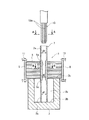
【解決手段】 ステータに対して回転可能なロータ1を、ロータコア5と、ロータコア5の中心部に設けた挿入孔5aに挿入固定する中空のロータシャフト7とから構成する。ロータコア5の挿入孔5aに挿入した状態のロータシャフト7の中空部に、外周に軸線方向に延びる突状13aを複数備えるマンドレル13を挿入して中空部内面を塑性変形させる。この塑性変形によって、ロータシャフト7の外周部を、外側に突出変形させてロータコア5の挿入孔5aの内面に押し付け、ロータコア5とロータシャフト7とを互いに固定する。
【選択図】 図1PROBLEM TO BE SOLVED: To prevent deterioration of workability when assembling a rotor core and a rotor shaft.
A rotor 1 that is rotatable with respect to a stator is composed of a rotor core 5 and a hollow rotor shaft 7 that is inserted and fixed in an insertion hole 5a provided in the center of the rotor core 5. A mandrel 13 having a plurality of protrusions 13a extending in the axial direction on the outer periphery is inserted into the hollow portion of the rotor shaft 7 in a state of being inserted into the insertion hole 5a of the rotor core 5 to plastically deform the inner surface of the hollow portion. By this plastic deformation, the outer peripheral portion of the rotor shaft 7 is projected and deformed outward and pressed against the inner surface of the insertion hole 5a of the rotor core 5 to fix the rotor core 5 and the rotor shaft 7 to each other.
[Selection] Figure 1
Description
本発明は、ステータに対して回転可能なロータを、ロータコアと、このロータコアの中心部に設けた挿入孔に挿入固定するロータシャフトとから構成した回転電機用ロータの製造方法および回転電機用ロータに関する。 The present invention relates to a method for manufacturing a rotor for a rotating electrical machine, and a rotor for a rotating electrical machine, in which a rotor that is rotatable with respect to a stator is composed of a rotor core and a rotor shaft that is inserted into and fixed to an insertion hole provided at the center of the rotor core. .
回転電機として、例えばモータは、ロータとステータとから構成され、これらロータとステータは、それぞれ別々にサブアッセンブリされる。このうちロータは、永久磁石と、永久磁石が入る円柱状のロータコアと、ロータコアの中心部に設けた挿入孔に挿入固定するロータシャフトとから構成される。 As a rotating electrical machine, for example, a motor is composed of a rotor and a stator, and these rotor and stator are sub-assembled separately. Of these, the rotor is composed of a permanent magnet, a cylindrical rotor core into which the permanent magnet is inserted, and a rotor shaft that is inserted into and fixed to an insertion hole provided in the center of the rotor core.
そして、ロータコアはロータシャフトに対し、例えば下記特許文献1に記載されているように、焼き嵌めにより固定される。
上記したように、従来では、ロータコアとロータシャフトとは、焼き嵌めによって互いに固定しているため、ロータコアの加熱や、焼き嵌め後のロータコアおよびロータシャフトの冷却に時間がかかり、組付作業性の悪化を招いている。 As described above, conventionally, since the rotor core and the rotor shaft are fixed to each other by shrink fitting, it takes time to heat the rotor core and cool the rotor core and rotor shaft after shrink fitting. Deteriorating.
そこで、本発明は、ロータコアとロータシャフトとを組み付ける際に、作業性の悪化を防止することを目的としている。 Then, this invention aims at preventing the deterioration of workability | operativity, when a rotor core and a rotor shaft are assembled | attached.
本発明は、ステータに対して回転可能なロータを、ロータコアと、このロータコアの中心部に設けた挿入孔に挿入固定する中空のロータシャフトとから構成し、前記ロータコアの挿入孔に挿入した状態の前記ロータシャフトの中空部に、外周部に凹凸を有するマンドレルを挿入して中空部内面を塑性変形させ、この塑性変形によって前記ロータシャフトの外周部を外側に突出変形させて前記ロータコアの挿入孔内面に押し付け、前記ロータコアと前記ロータシャフトとを互いに固定することを最も主要な特徴とする。 The present invention comprises a rotor that is rotatable with respect to a stator, comprising a rotor core and a hollow rotor shaft that is inserted and fixed in an insertion hole provided in the center of the rotor core, and is inserted into the insertion hole of the rotor core. An inner surface of the insertion hole of the rotor core is formed by inserting a mandrel having irregularities on the outer peripheral portion into the hollow portion of the rotor shaft to plastically deform the inner surface of the hollow portion, and projecting and deforming the outer peripheral portion of the rotor shaft outward by the plastic deformation. And the rotor core and the rotor shaft are fixed to each other.
本発明によれば、ロータコアの挿入孔に挿入した状態のロータシャフトの中空部に、外周に凹凸を有するマンドレルを挿入して中空部内面を塑性変形させ、この塑性変形によってロータシャフトの外周部を外側に突出変形させてロータコアの挿入孔内面に押し付けて固定するようにしたため、焼き嵌めによる固定のような、ロータコアの加熱や、焼き嵌め後のロータコアおよびロータシャフトの冷却作業が不要となり、組付作業性を向上させることができる。 According to the present invention, the inner surface of the rotor shaft is plastically deformed by inserting a mandrel having irregularities on the outer periphery thereof into the hollow portion of the rotor shaft that is inserted into the insertion hole of the rotor core, and the outer peripheral portion of the rotor shaft is deformed by this plastic deformation. Since it is deformed to protrude outward and pressed against the inner surface of the insertion hole of the rotor core, it is not necessary to heat the rotor core and to cool the rotor core and rotor shaft after shrink fitting, such as fixing by shrink fitting. Workability can be improved.
また、組付後は、ロータシャフトの中空部内周に塑性変形による凹部が形成されるので、ロータシャフトの内部に冷却剤を供給してロータを内側から冷却する場合に、ロータシャフトにおける冷却剤との接触面積が大きくなり、冷却効果を高めることができる。 In addition, after assembly, a recess due to plastic deformation is formed in the inner periphery of the hollow portion of the rotor shaft, so that when the coolant is supplied into the rotor shaft to cool the rotor from the inside, the coolant in the rotor shaft The contact area becomes larger, and the cooling effect can be enhanced.
以下、本発明の実施の形態を図面に基づき説明する。 Hereinafter, embodiments of the present invention will be described with reference to the drawings.
図1は、本発明の一実施形態に係わる回転電機用ロータとしてのモータにおけるロータ1を、突き当て治具3にセットした状態を示す断面図である。ロータ1は、円板状のロータ板を図1中で上下方向に複数積層した円柱状のロータコア5と、ロータコア5の中心部に設けた挿入孔5aに挿入固定する中空状のロータシャフト7とをそれぞれ有し、図示しないハウジング内に固定されたステータに対して回転可能となる。
FIG. 1 is a cross-sectional view showing a state in which a
ロータシャフト7は、ロータコア5の挿入孔5aに挿入した状態で、ロータコア5に対して図1中で上下に突出する部位7a,7bをそれぞれ備え、これら各部位7a,7b相互間のロータコア5に対応する部位7cの肉厚を、前記した各部位7a,7bの肉厚より、内側に突出するように厚くしている。また、このときロータコア5に対応する部位7cの外周面は、挿入孔5aにほぼ接触した状態となる。
The
突き当て治具3は、図1中で上部に開放する凹部3aを備え、この凹部3aにロータシャフト7の下部側の部位7bを入り込ませ、その先端を凹部3aの底面3bに突き当てる。このときロータコア5は、突き当て治具3の上端面3cに載置された状態となる。
The abutting jig 3 includes a
また、ロータコア5の外周側には、円周方向等間隔の少なくとも3箇所に、ガイドローラ9を設置する。ガイドローラ9は、ロータコア5の軸心を後述するマンドレル13の軸心に合わせるとともに、組付作業時にロータコア5を外周側から押さえるものであり、支持部11に対して回転可能かつ、支持部11とともにロータコア5に対しその径方向に向けて接近離反移動可能である。
In addition,
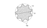
前記したマンドレル13は、図1の拡大したA−A断面図である図2に示すように、外周部に、軸方向に向けて延びる凹凸としての突条13aを、円周方向に沿って複数等間隔に設けてある。
As shown in FIG. 2, which is an enlarged cross-sectional view taken along the line AA in FIG. 1, the
マンドレル13の突条13aの先端位置における外径Dは、ロータシャフト7のロータコア5から上下に突出した部位7a,7bの内径d1より小さく、ロータコア5に対応する部位7cの内径d2より大きく設定している。つまり、d1>D>d2である。
The outer diameter D of the
また、マンドレル13の軸心は、前記した複数のガイドローラ9によって合わせるロータコア5およびロータシャフト7の各中心に一致している。
Further, the axis of the
次に、上記したロータ1の製造方法について説明する。
Next, a method for manufacturing the
まず、突き当て治具3の上端面3cにロータコア5を載置してセットする。このときガイドローラ9は、ロータコア5から離反した位置にあり、ロータコア5を突き当て治具3にセットした後、ロータコア5に向けて接近させて押し付け、ロータコア5の軸心をマンドレル13の軸心に合わせる。
First, the
その後、ロータシャフト7をロータコア5の挿入孔5aに挿入し、ロータシャフト7の先端(下端)を、突き当て治具3の凹部3aに入り込ませて底部3bに突き当てる。この状態で、ロータシャフト7の肉厚となっている部位7cが、ロータコア5に対応する位置となる。
Thereafter, the
次に、マンドレル13を、ロータシャフト7の上方からその中空部に挿入すると、ロータコア5に対応する部位7cでは、中空部内周面が突条13aによって塑性変形する結果、図1の拡大したB−B断面図である図3に示すように、中空部内周面にマンドレル13の突条13aに対応して軸方向に延びる凹部7ciが、円周方向等間隔に複数形成される。
Next, when the
そして、この凹部7ciに対応するロータシャフト7の外周部には、凸部7coが外側に突出して形成され、この凸部7coがロータコア5の挿入孔5aの内周面に押し付けることで、ロータコア5とロータシャフト7とを互いに固定する。
And the convex part 7co protrudes and is formed in the outer peripheral part of the
その後、ロータ1を図示しない適宜手段によって押さえた状態で、マンドレル13をロータシャフト7から引き抜く。
Thereafter, the
上記したように、本実施形態によれば、ロータコア5の挿入孔5aに挿入した状態のロータシャフト7の中空部に、外周部に突条13aを備えたマンドレル13を挿入して中空部内面を塑性変形させ、この塑性変形によってロータシャフト7の外周部を外側に突出変形させてロータコア5の挿入孔5aの内周面に押し付けて固定するようにしたため、焼き嵌めによる固定のような、ロータコア5の加熱や、焼き嵌め後のロータコア5およびロータシャフト7の冷却作業が不要となり、組付作業性を向上させることができる。
As described above, according to the present embodiment, the
また、組付後は、ロータシャフト7の内周面に、軸方向に延びる凹部7ciが形成されるので、ロータシャフト7の内部に冷却剤を供給してロータ1を内側から冷却する場合に、ロータシャフト7の冷却剤に対する接触面積が大きくなり、冷却効果が向上する。
In addition, after assembly, a recess 7ci extending in the axial direction is formed on the inner peripheral surface of the
また、ロータシャフト7における塑性変形させる部位を、ロータコア5に対応する部位7cのみとしているので、ロータシャフト7の全長にわたり塑性変形させる場合に比べ、マンドレル13の塑性変形時でのストローク量が少なくて済み、作業時間の低減およびマンドレル13の長寿命化が達成できる。
Further, since the portion of the
さらに、ロータコア5に対応する塑性変形させる部位7cを、他の部位7a,7bに比べて厚肉とすることで、図3に示すように、中空部内面での凹部7ciの塑性変形量を大きくして、外側への凸部7coの突出量を適度に抑え、これによりロータコア5とロータシャフト7との固定を確実に行いつつロータコア5のダメージを極力低減することができる。
Further, by making the
本発明によれば、前記ロータシャフトは、前記ロータコアの軸方向両端から突出する部位を備え、前記マンドレルによって塑性変形させる部位は、前記ロータコアに対応する部位としたので、ロータシャフトの全長にわたり塑性変形させる場合に比べ、マンドレルのストローク量が少なくて済み、作業時間の低減およびマンドレルの長寿命化が達成できる。 According to the present invention, the rotor shaft includes portions protruding from both axial ends of the rotor core, and the portion to be plastically deformed by the mandrel is a portion corresponding to the rotor core. Compared with the case of making it possible, the stroke amount of the mandrel can be reduced, and the working time can be reduced and the life of the mandrel can be extended.
また、前記ロータコアに対応する前記ロータシャフトの部位は、ロータシャフトの他の部位に比べて厚肉としたので、ロータシャフトの中空部内面での塑性変形量を大きくして、外側への突出量を適度に抑え、これによりロータコアとロータシャフトとの固定を確実に行いつつロータコアのダメージを極力低減することができる。 Further, since the portion of the rotor shaft corresponding to the rotor core is thicker than other portions of the rotor shaft, the amount of plastic deformation on the inner surface of the hollow portion of the rotor shaft is increased, and the amount of protrusion to the outside Thus, the damage to the rotor core can be reduced as much as possible while reliably fixing the rotor core and the rotor shaft.
1 ロータ
5 ロータコア
5a ロータコアの挿入孔
7 ロータシャフト
7a,7b ロータコアの両端から突出するロータシャフトの部位
7c ロータコアに対応するロータシャフトの部位
13 マンドレル
13a 突状(凹凸)
DESCRIPTION OF
Claims (4)
Priority Applications (1)
| Application Number | Priority Date | Filing Date | Title |
|---|---|---|---|
| JP2004110124A JP2005295745A (en) | 2004-04-02 | 2004-04-02 | Manufacturing method of rotor for rotating electrical machine and rotor for rotating electrical machine |
Applications Claiming Priority (1)
| Application Number | Priority Date | Filing Date | Title |
|---|---|---|---|
| JP2004110124A JP2005295745A (en) | 2004-04-02 | 2004-04-02 | Manufacturing method of rotor for rotating electrical machine and rotor for rotating electrical machine |
Publications (1)
| Publication Number | Publication Date |
|---|---|
| JP2005295745A true JP2005295745A (en) | 2005-10-20 |
Family
ID=35328062
Family Applications (1)
| Application Number | Title | Priority Date | Filing Date |
|---|---|---|---|
| JP2004110124A Pending JP2005295745A (en) | 2004-04-02 | 2004-04-02 | Manufacturing method of rotor for rotating electrical machine and rotor for rotating electrical machine |
Country Status (1)
| Country | Link |
|---|---|
| JP (1) | JP2005295745A (en) |
Cited By (9)
| Publication number | Priority date | Publication date | Assignee | Title |
|---|---|---|---|---|
| JP2009095089A (en) * | 2007-10-04 | 2009-04-30 | Honda Motor Co Ltd | Axial gap type motor |
| JP4786702B2 (en) * | 2006-02-16 | 2011-10-05 | 三菱電機株式会社 | Cooling structure of rotating electric machine |
| JP2014108020A (en) * | 2012-11-29 | 2014-06-09 | Honda Motor Co Ltd | Rotor position adjustment device, rotor position adjustment method and manufacturing method of rotary electric machine |
| CN103904851A (en) * | 2014-03-28 | 2014-07-02 | 湖北立锐机电有限公司 | Magnetic ring structure, shaft and permanent magnet synchronous motor with magnetic ring structure and shaft |
| CN109067108A (en) * | 2018-09-12 | 2018-12-21 | 山西电机制造有限公司 | A kind of threephase asynchronous cast-aluminum rotor low-voltage cast aluminum dummy shaft structure |
| JP2019106797A (en) * | 2017-12-12 | 2019-06-27 | トヨタ自動車株式会社 | Rotor manufacturing method |
| US10916996B2 (en) | 2017-10-13 | 2021-02-09 | Toyota Jtdosha Kabushiki Kaisha | Method of manufacturing rotational electric machine rotor |
| KR20220149440A (en) * | 2021-04-30 | 2022-11-08 | 독터. 인제니어. 하.체. 에프. 포르쉐 악티엔게젤샤프트 | Joining tool for pressing a disk to a shaft, and rotor shaft for an electric machine |
| EP4340181A1 (en) * | 2022-09-14 | 2024-03-20 | voestalpine Automotive Components Dettingen GmbH & Co. KG | Method for producing a fixed connection between a laminated core and an internally hollow component |
Citations (2)
| Publication number | Priority date | Publication date | Assignee | Title |
|---|---|---|---|---|
| JPH05260704A (en) * | 1992-03-06 | 1993-10-08 | Mitsuba Electric Mfg Co Ltd | How to attach the armature core |
| JPH11270307A (en) * | 1998-03-24 | 1999-10-05 | Nippon Seiko Kk | Assembled camshaft for engine |
-
2004
- 2004-04-02 JP JP2004110124A patent/JP2005295745A/en active Pending
Patent Citations (2)
| Publication number | Priority date | Publication date | Assignee | Title |
|---|---|---|---|---|
| JPH05260704A (en) * | 1992-03-06 | 1993-10-08 | Mitsuba Electric Mfg Co Ltd | How to attach the armature core |
| JPH11270307A (en) * | 1998-03-24 | 1999-10-05 | Nippon Seiko Kk | Assembled camshaft for engine |
Cited By (17)
| Publication number | Priority date | Publication date | Assignee | Title |
|---|---|---|---|---|
| JP4786702B2 (en) * | 2006-02-16 | 2011-10-05 | 三菱電機株式会社 | Cooling structure of rotating electric machine |
| JP2009095089A (en) * | 2007-10-04 | 2009-04-30 | Honda Motor Co Ltd | Axial gap type motor |
| JP2014108020A (en) * | 2012-11-29 | 2014-06-09 | Honda Motor Co Ltd | Rotor position adjustment device, rotor position adjustment method and manufacturing method of rotary electric machine |
| CN103904851A (en) * | 2014-03-28 | 2014-07-02 | 湖北立锐机电有限公司 | Magnetic ring structure, shaft and permanent magnet synchronous motor with magnetic ring structure and shaft |
| US11271460B2 (en) | 2017-10-13 | 2022-03-08 | Toyota Jidosha Kabushiki Kaisha | Method of manufacturing a rotational electric machine rotor |
| US10916996B2 (en) | 2017-10-13 | 2021-02-09 | Toyota Jtdosha Kabushiki Kaisha | Method of manufacturing rotational electric machine rotor |
| US11258341B2 (en) | 2017-10-13 | 2022-02-22 | Toyota Jidosha Kabushiki Kaisha | Rotational electric machine rotor |
| JP2019106797A (en) * | 2017-12-12 | 2019-06-27 | トヨタ自動車株式会社 | Rotor manufacturing method |
| CN109980864A (en) * | 2017-12-12 | 2019-07-05 | 丰田自动车株式会社 | Method for manufacturing rotor |
| US11165314B2 (en) | 2017-12-12 | 2021-11-02 | Toyota Jidosha Kabushiki Kaisha | Rotor manufacturing method |
| CN109980864B (en) * | 2017-12-12 | 2022-02-25 | 丰田自动车株式会社 | Rotor manufacturing method |
| CN109067108A (en) * | 2018-09-12 | 2018-12-21 | 山西电机制造有限公司 | A kind of threephase asynchronous cast-aluminum rotor low-voltage cast aluminum dummy shaft structure |
| KR20220149440A (en) * | 2021-04-30 | 2022-11-08 | 독터. 인제니어. 하.체. 에프. 포르쉐 악티엔게젤샤프트 | Joining tool for pressing a disk to a shaft, and rotor shaft for an electric machine |
| KR102807517B1 (en) * | 2021-04-30 | 2025-05-16 | 독터. 인제니어. 하.체. 에프. 포르쉐 악티엔게젤샤프트 | Joining tool for pressing a disk to a shaft, and rotor shaft for an electric machine |
| US12334783B2 (en) | 2021-04-30 | 2025-06-17 | Dr. Ing. H. C. F. Porsche Ag | Joining tool for pressing a disk to a shaft, and rotor shaft for an electric machine |
| EP4340181A1 (en) * | 2022-09-14 | 2024-03-20 | voestalpine Automotive Components Dettingen GmbH & Co. KG | Method for producing a fixed connection between a laminated core and an internally hollow component |
| WO2024056839A1 (en) * | 2022-09-14 | 2024-03-21 | voestalpine Automotive Components Dettingen GmbH & Co. KG | Method for producing a rigid connection between a laminated core and an inner hollow component |
Similar Documents
| Publication | Publication Date | Title |
|---|---|---|
| AU674784B2 (en) | Electric rotating machine | |
| CN105846564B (en) | Motor and stator structure thereof | |
| US5864193A (en) | Electric rotating machine having improved insulation for an armature coil | |
| US20050050714A1 (en) | Manufacturing method for a motor layered core, manufacturing apparatus thereof, and stacking jig thereof | |
| US7049726B2 (en) | Stator for dynamo-electric machine | |
| CN1310507A (en) | Motor stator-core and its producing method, and electric motor and compressor | |
| US7546672B2 (en) | Methods for manufacturing a motor | |
| JP2005295745A (en) | Manufacturing method of rotor for rotating electrical machine and rotor for rotating electrical machine | |
| CN112134377A (en) | Stator, method of manufacturing stator, and outer rotor type motor | |
| JP2005110464A (en) | Stator core of electric motor and method for manufacturing the same | |
| JP2014033549A (en) | Rotor, rotary electric machine and method for manufacturing rotor | |
| JP2005295744A (en) | Manufacturing method of rotor for rotating electrical machine and rotor for rotating electrical machine | |
| JP2002291186A (en) | Flat wire winding structure and winding method | |
| US20060186753A1 (en) | Stator and electric motor having the same | |
| JPWO2018043364A1 (en) | Winding fixed structure and motor | |
| JP4855069B2 (en) | Manufacturing method of motor | |
| JPH05292708A (en) | Method of manufacturing split stator | |
| US7877857B2 (en) | Manufacturing method of electric motor | |
| US20100231086A1 (en) | Manufacturing method of rotating electric machine and rotating electric machine | |
| US7795775B2 (en) | Motor stator | |
| WO2018131205A1 (en) | Rotating electric machine stator and rotating electric machine stator manufacturing method | |
| JP4679374B2 (en) | Motor and manufacturing method thereof | |
| JP4648716B2 (en) | Laminated iron core and manufacturing method thereof | |
| CN100334794C (en) | Method and device for manufacturing flat commutator | |
| JP6848348B2 (en) | Rotor manufacturing method |
Legal Events
| Date | Code | Title | Description |
|---|---|---|---|
| A621 | Written request for application examination |
Free format text: JAPANESE INTERMEDIATE CODE: A621 Effective date: 20070226 |
|
| A977 | Report on retrieval |
Free format text: JAPANESE INTERMEDIATE CODE: A971007 Effective date: 20100223 |
|
| A131 | Notification of reasons for refusal |
Free format text: JAPANESE INTERMEDIATE CODE: A131 Effective date: 20100302 |
|
| A02 | Decision of refusal |
Free format text: JAPANESE INTERMEDIATE CODE: A02 Effective date: 20100706 |