JP2005295744A - Method of manufacturing rotor for rotary electric machine and rotor for rotary electric machine - Google Patents
Method of manufacturing rotor for rotary electric machine and rotor for rotary electric machine Download PDFInfo
- Publication number
- JP2005295744A JP2005295744A JP2004110117A JP2004110117A JP2005295744A JP 2005295744 A JP2005295744 A JP 2005295744A JP 2004110117 A JP2004110117 A JP 2004110117A JP 2004110117 A JP2004110117 A JP 2004110117A JP 2005295744 A JP2005295744 A JP 2005295744A
- Authority
- JP
- Japan
- Prior art keywords
- rotor
- hole
- rotor shaft
- shaft
- rotor core
- Prior art date
- Legal status (The legal status is an assumption and is not a legal conclusion. Google has not performed a legal analysis and makes no representation as to the accuracy of the status listed.)
- Pending
Links
Images
Landscapes
- Iron Core Of Rotating Electric Machines (AREA)
- Manufacture Of Motors, Generators (AREA)
Abstract
Description
本発明は、ステータに対して回転可能なロータを、ロータ板を複数積層したロータコアと、このロータコアの中心に設けた挿入孔に挿入固定するロータシャフトとから構成した回転電機用ロータの製造方法および回転電機用ロータに関する。 The present invention relates to a method for manufacturing a rotor for a rotating electrical machine, in which a rotor rotatable with respect to a stator is composed of a rotor core in which a plurality of rotor plates are laminated, and a rotor shaft that is inserted and fixed in an insertion hole provided at the center of the rotor core. The present invention relates to a rotor for a rotating electrical machine.
回転電機として、例えばモータは、ロータとステータとから構成され、これらロータとステータは、それぞれ別々にサブアッセンブリされる。このうちロータは、永久磁石と、永久磁石が入る円柱状のロータコアと、ロータコアの中心部に設けた挿入孔に挿入固定するロータシャフトとから構成される。 As a rotating electrical machine, for example, a motor is composed of a rotor and a stator, and these rotor and stator are sub-assembled separately. Of these, the rotor is composed of a permanent magnet, a cylindrical rotor core into which the permanent magnet is inserted, and a rotor shaft that is inserted into and fixed to an insertion hole provided in the center of the rotor core.
そして、ロータコアはロータシャフトに対し、例えば下記特許文献1に記載されているように、焼き嵌めにより固定される。
上記したように、従来では、ロータコアとロータシャフトとは、焼き嵌めによって互いに固定しているため、ロータコアの加熱や、焼き嵌め後のロータコアおよびロータシャフトの冷却に時間がかかり、組付作業性の悪化を招いている。 As described above, conventionally, since the rotor core and the rotor shaft are fixed to each other by shrink fitting, it takes time to heat the rotor core and cool the rotor core and rotor shaft after shrink fitting. Deteriorating.
そこで、本発明は、ロータコアとロータシャフトとを組み付ける際に、作業性の悪化を防止することを目的としている。 Then, this invention aims at preventing the deterioration of workability | operativity, when a rotor core and a rotor shaft are assembled | attached.
本発明は、ステータに対して回転可能なロータを、ロータ板を複数積層したロータコアと、このロータコアの中心部に設けた挿入孔に挿入固定するロータシャフトとから構成し、前記ロータコアの挿入孔に対応する前記各ロータ板の貫通孔の内周縁を軸方向に向けて屈曲させて突出部を形成し、かつこの突出部を形成した状態での前記貫通孔の内径を前記ロータシャフトの外径より大きく形成し、この大きく形成した貫通孔に前記ロータシャフトを挿入して仮組み付けし、この仮組み付け状態で、前記貫通孔の内周縁の前記突出部を軸方向に加圧して貫通孔の内径を小さくしその内周縁を前記ロータシャフトの外周面に食い込ませて前記ロータコアと前記ロータシャフトとを互いに固定することを最も主要な特徴とする。 The present invention comprises a rotor that is rotatable with respect to a stator, comprising a rotor core in which a plurality of rotor plates are stacked, and a rotor shaft that is inserted and fixed in an insertion hole provided in the center of the rotor core. The inner peripheral edge of the corresponding through hole of each rotor plate is bent in the axial direction to form a protrusion, and the inner diameter of the through hole in the state where the protrusion is formed is larger than the outer diameter of the rotor shaft. The rotor shaft is inserted into the large formed through hole and temporarily assembled, and in this temporarily assembled state, the projecting portion on the inner peripheral edge of the through hole is axially pressed to reduce the inner diameter of the through hole. The main feature is that the rotor core and the rotor shaft are fixed to each other by making the inner periphery of the rotor shaft smaller and biting into the outer peripheral surface of the rotor shaft.
本発明によれば、ロータ板に形成した貫通孔の内周縁の突出部を加圧して変形させることで、ロータコアとロータシャフトとを固定するようにしたので、焼き嵌めによる固定のような、ロータコアの加熱や、焼き嵌め後のロータコアおよびロータシャフトの冷却作業が不要となり、組付作業性を向上させることができる。 According to the present invention, the rotor core and the rotor shaft are fixed by pressurizing and deforming the protruding portion of the inner peripheral edge of the through hole formed in the rotor plate, so that the rotor core is fixed by shrink fitting. Heating and cooling work of the rotor core and rotor shaft after shrink fitting are unnecessary, and the assembly workability can be improved.
以下、本発明の実施の形態を図面に基づき説明する。 Hereinafter, embodiments of the present invention will be described with reference to the drawings.
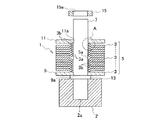
図1は、本発明の第1の実施形態に係わる回転電機用ロータとしてのモータにおけるロータ1を、仮組治具2上にセットした状態を示す断面図である。ロータ1は、円板状のロータ板3を図1中で上下方向に複数積層した円柱状のロータコア5と、ロータコア5の中心部に設けた挿入孔5aに挿入固定するロータシャフト7とをそれぞれ有し、図示しないハウジング内に固定されたステータに対して回転可能となる。
FIG. 1 is a cross-sectional view showing a state where a rotor 1 in a motor as a rotor for a rotating electrical machine according to the first embodiment of the present invention is set on a
ロータコア5の積層方向両側には、エンドプレート9,11をそれぞれ配置し、この各エンドプレート9,11も、中心部に形成した挿入孔9a,11aにロータシャフト7がそれぞれ挿入される。
図1中で下部のエンドプレート9のロータコア5と反対側のロータシャフト7には、中心部に図示しない圧入孔を備えたスリーブ13を圧入固定し、このスリーブ13より下部側のロータシャフト7を前記した仮組治具2の凹部2aに挿入した状態で、スリーブ13を仮組治具2の上面に当接させる。
In FIG. 1, a
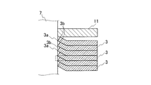
ここで、ロータシャフト7をロータコア5の挿入孔5aに挿入する際には、図1のA部の拡大した断面図である図2に示すように、ロータコア5における各ロータ板3の貫通孔3aは、その内周縁を、軸方向に向けて屈曲させて突出させ、突出部3bを形成している。このとき、貫通孔3aの内周縁はロータシャフト7の外周面にほぼ接触した状態となる。
Here, when the
上記した突出部3bは、貫通孔3aをプレスにより打ち抜き加工する際に発生するかえり(バリ)であり、打ち抜き加工後に別途加工を行う必要がない。このため、突出部3bの形成は容易に行える。
The
なお、貫通孔3aの内周縁に突出部3bを形成する前の状態、すなわち打ち抜き加工後にバリが形成されないと仮定した状態では、図2中で二点鎖線で示すように、貫通孔の内径はロータシャフト7の外径より小さくなっている。
In the state before the
次に、上記したロータ1の製造方法について説明する。 Next, a method for manufacturing the rotor 1 will be described.
図1に示すように、仮組治具2の凹部2aに、ロータシャフト7の下端を挿入してセットした状態で、一方のエンドプレート9を、その挿入孔9aにロータシャフト7を挿入させつつロータシャフト7にセットしてスリーブ13上に載せる。
As shown in FIG. 1, while the lower end of the
次に、複数のロータ板3を、その貫通孔3aにロータシャフト7を挿入しつつロータシャフト7にセットするが、このとき複数のロータ板3のうち図1中で下部側の半分を、突出部3bが下方のエンドプレート9に向くようにし、残りの図1中で上部側の半分を、突出部3bが上方のエンドプレート11に向くようにする。すなわち、複数のロータ板3の各突出部3bは、ロータコア5の積層方向ほぼ中心部を境にして軸方向両側に位置するロータ板3が、互いに逆方向かつ軸方向外側に向いていることになる。
Next, the plurality of
複数のロータ板3からなるロータコア5の上には、さらに他方のエンドプレート11を、その貫通孔11aにロータシャフト7を挿入させつつロータシャフト7にセットする。
On the
そして、上部のエンドプレート11の上から、スリーブ15を、その圧入孔15aを利用してロータシャフト7に圧入するが、この圧入時に、図3に示してある加圧用治具17を用いる。
Then, the
加圧用治具17は、凹部17aを備えており、その凹部17aにロータシャフト7の上部を挿入した状態とする。この状態で加圧用治具17の加圧部17bをスリーブ15に当接させ、仮組治具2との間で、積層している複数のロータ板3を加圧する。この加圧によって、ロータ板3の貫通孔3aの突出部3bを押し潰してほぼ平坦とし、貫通孔3aの内周縁をロータシャフト7の外周面に食い込ませて固定する。
The pressurizing
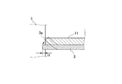
図4は、1枚のロータ板3の貫通孔3aの内周縁が、上記した加圧によってロータシャフト7の外周面に食い込んだ状態を実線で示している。これにより、ロータ板3とロータシャフト7との間には、締め代Hが形成されて、ロータコア5とロータシャフト7とを確実に固定することができる。
FIG. 4 shows a state in which the inner peripheral edge of the through-
この場合、ロータコア5とロータシャフト7とは、従来のような焼き嵌めによる固定を行っていないため、ロータコア5の加熱や、焼き嵌め後のロータコア5およびロータシャフト7の冷却が不要であり、組付作業性が向上する。
In this case, since the
また、複数のロータ板3は、その貫通孔3aの内周縁の突出部3bが、ロータコア5の積層方向ほぼ中心部を境にして、図1中で下部側のものと同上部側のものとで、互いに逆方向かつ軸方向外側に向いているので、すべての突出部3bを同一方向に向かせる場合に比べ、加圧によるロータ板3の1枚1枚の変形量を均一化することができる。
Further, the plurality of
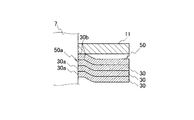
図5は、この発明の第2の実施形態を示す、前記図2に対応する断面図である。この実施形態は、ロータ板30に貫通孔30aを打ち抜き加工した後に、軸方向に突出する突出部30bを、それより外周側の面に対して段差を有する面となるよう後加工している。
FIG. 5 is a cross-sectional view corresponding to FIG. 2, showing a second embodiment of the present invention. In this embodiment, after punching the through
そして、第1の実施形態と同様に、積層した複数のロータ板30を軸方向に加圧することで、突出部30bを押し潰してロータ板30の全体ををほぼ平坦とし、貫通孔30aの内周縁をロータシャフト7の外周面に食い込ませて固定する。
As in the first embodiment, the plurality of laminated
本発明によれば、前記複数のロータ板の各突出部は、前記ロータコアの積層方向ほぼ中心部を境にして軸方向両側に位置するロータ板が、互いに逆方向かつ軸方向外側に向いて突出しているので、すべての突出部を同一方向に向かせる場合に比べ、ロータ板の1枚1枚の加圧による変形量を均一化することができる。 According to the present invention, the projecting portions of the plurality of rotor plates are such that the rotor plates located on both sides in the axial direction from the substantially central portion in the stacking direction of the rotor cores project in opposite directions and outward in the axial direction. Therefore, as compared with the case where all the protrusions are directed in the same direction, the amount of deformation of each rotor plate due to pressurization can be made uniform.
また、前記突出部は、前記ロータ板の貫通孔を打ち抜き成形する際のバリであることから、突出部を形成するための後加工を別途行う必要がなく、突出部の形成を容易にできる。 In addition, since the protrusion is a burr when the through hole of the rotor plate is punched and formed, it is not necessary to separately perform post-processing for forming the protrusion, and the protrusion can be easily formed.
1 ロータ
3,30 ロータ板
3a,30a ロータ板の貫通孔
3b,30b 貫通孔の内周縁の突出部
5,50 ロータコア
5a,50 ロータコアの挿入孔
7 ロータシャフト
DESCRIPTION OF SYMBOLS 1
Claims (4)
Priority Applications (1)
| Application Number | Priority Date | Filing Date | Title |
|---|---|---|---|
| JP2004110117A JP2005295744A (en) | 2004-04-02 | 2004-04-02 | Method of manufacturing rotor for rotary electric machine and rotor for rotary electric machine |
Applications Claiming Priority (1)
| Application Number | Priority Date | Filing Date | Title |
|---|---|---|---|
| JP2004110117A JP2005295744A (en) | 2004-04-02 | 2004-04-02 | Method of manufacturing rotor for rotary electric machine and rotor for rotary electric machine |
Publications (1)
| Publication Number | Publication Date |
|---|---|
| JP2005295744A true JP2005295744A (en) | 2005-10-20 |
Family
ID=35328061
Family Applications (1)
| Application Number | Title | Priority Date | Filing Date |
|---|---|---|---|
| JP2004110117A Pending JP2005295744A (en) | 2004-04-02 | 2004-04-02 | Method of manufacturing rotor for rotary electric machine and rotor for rotary electric machine |
Country Status (1)
| Country | Link |
|---|---|
| JP (1) | JP2005295744A (en) |
Cited By (15)
| Publication number | Priority date | Publication date | Assignee | Title |
|---|---|---|---|---|
| JP2008220112A (en) * | 2007-03-07 | 2008-09-18 | Mitsubishi Electric Corp | Stator, closed type compressor, and rotating machine |
| JP2010028885A (en) * | 2008-07-15 | 2010-02-04 | Toyota Motor Corp | Core for rotating electrical machines |
| JP2011152041A (en) * | 2011-03-25 | 2011-08-04 | Mitsubishi Electric Corp | Stator, sealed compressor and rotating machine |
| US8235278B2 (en) * | 2009-10-26 | 2012-08-07 | Toyota Boshoku Kabushiki Kaisha | Press method and press apparatus |
| JP2013031328A (en) * | 2011-07-29 | 2013-02-07 | Hitachi Automotive Systems Ltd | Rotary electric machine |
| WO2013118294A1 (en) * | 2012-02-10 | 2013-08-15 | トヨタ自動車株式会社 | Core-shaft fastening method and fastening structure |
| DE102013110141A1 (en) | 2012-09-27 | 2014-03-27 | Denso Corporation | Rotating electrical machine |
| DE102008006074B4 (en) * | 2007-01-30 | 2014-09-11 | GM Global Technology Operations LLC (n. d. Ges. d. Staates Delaware) | Rotor of a permanent magnet machine |
| JP2015154665A (en) * | 2014-02-18 | 2015-08-24 | 株式会社ジェイテクト | Rotor, and method of manufacturing the rotor |
| JP2017038476A (en) * | 2015-08-10 | 2017-02-16 | トヨタ自動車株式会社 | Shrinkage fitting method for laminate rotor |
| JP2018182795A (en) * | 2017-04-04 | 2018-11-15 | 日産自動車株式会社 | Method of manufacturing rotor for electric motor, and rotor for electric motor |
| EP3550698A4 (en) * | 2016-11-29 | 2019-11-27 | Panasonic Intellectual Property Management Co., Ltd. | Electric motor rotor, electric motor equipped with same, and manufacturing method for said rotor |
| WO2021005794A1 (en) * | 2019-07-11 | 2021-01-14 | 三菱電機株式会社 | Rotor for rotary electric machine and method for manufacturing same |
| CN113366732A (en) * | 2019-01-18 | 2021-09-07 | 西门子股份公司 | Joining laminations on a shaft |
| DE102020214377A1 (en) | 2020-11-16 | 2022-05-19 | Volkswagen Aktiengesellschaft | Rotor assembly with clamping blade |
Citations (3)
| Publication number | Priority date | Publication date | Assignee | Title |
|---|---|---|---|---|
| JPS60152257A (en) * | 1984-01-17 | 1985-08-10 | Toshiba Corp | Manufacture of rotor of rotary electric machine |
| JPH02188147A (en) * | 1989-01-13 | 1990-07-24 | Matsushita Electric Ind Co Ltd | Manufacture of rotor for miniature motor |
| JPH0387817U (en) * | 1989-12-21 | 1991-09-06 |
-
2004
- 2004-04-02 JP JP2004110117A patent/JP2005295744A/en active Pending
Patent Citations (3)
| Publication number | Priority date | Publication date | Assignee | Title |
|---|---|---|---|---|
| JPS60152257A (en) * | 1984-01-17 | 1985-08-10 | Toshiba Corp | Manufacture of rotor of rotary electric machine |
| JPH02188147A (en) * | 1989-01-13 | 1990-07-24 | Matsushita Electric Ind Co Ltd | Manufacture of rotor for miniature motor |
| JPH0387817U (en) * | 1989-12-21 | 1991-09-06 |
Cited By (20)
| Publication number | Priority date | Publication date | Assignee | Title |
|---|---|---|---|---|
| DE102008006074B4 (en) * | 2007-01-30 | 2014-09-11 | GM Global Technology Operations LLC (n. d. Ges. d. Staates Delaware) | Rotor of a permanent magnet machine |
| JP2008220112A (en) * | 2007-03-07 | 2008-09-18 | Mitsubishi Electric Corp | Stator, closed type compressor, and rotating machine |
| JP2010028885A (en) * | 2008-07-15 | 2010-02-04 | Toyota Motor Corp | Core for rotating electrical machines |
| US8235278B2 (en) * | 2009-10-26 | 2012-08-07 | Toyota Boshoku Kabushiki Kaisha | Press method and press apparatus |
| JP2011152041A (en) * | 2011-03-25 | 2011-08-04 | Mitsubishi Electric Corp | Stator, sealed compressor and rotating machine |
| JP2013031328A (en) * | 2011-07-29 | 2013-02-07 | Hitachi Automotive Systems Ltd | Rotary electric machine |
| WO2013118294A1 (en) * | 2012-02-10 | 2013-08-15 | トヨタ自動車株式会社 | Core-shaft fastening method and fastening structure |
| DE102013110141B4 (en) | 2012-09-27 | 2023-03-09 | Denso Corporation | Rotating electric machine |
| DE102013110141A1 (en) | 2012-09-27 | 2014-03-27 | Denso Corporation | Rotating electrical machine |
| US9343937B2 (en) | 2012-09-27 | 2016-05-17 | Denso Corporation | Rotary electric machine equipped with rotor core of step skew structure |
| JP2015154665A (en) * | 2014-02-18 | 2015-08-24 | 株式会社ジェイテクト | Rotor, and method of manufacturing the rotor |
| JP2017038476A (en) * | 2015-08-10 | 2017-02-16 | トヨタ自動車株式会社 | Shrinkage fitting method for laminate rotor |
| EP3550698A4 (en) * | 2016-11-29 | 2019-11-27 | Panasonic Intellectual Property Management Co., Ltd. | Electric motor rotor, electric motor equipped with same, and manufacturing method for said rotor |
| JP2018182795A (en) * | 2017-04-04 | 2018-11-15 | 日産自動車株式会社 | Method of manufacturing rotor for electric motor, and rotor for electric motor |
| CN113366732A (en) * | 2019-01-18 | 2021-09-07 | 西门子股份公司 | Joining laminations on a shaft |
| CN113366732B (en) * | 2019-01-18 | 2024-03-05 | 西门子股份公司 | Joining laminations on a shaft |
| WO2021005794A1 (en) * | 2019-07-11 | 2021-01-14 | 三菱電機株式会社 | Rotor for rotary electric machine and method for manufacturing same |
| JPWO2021005794A1 (en) * | 2019-07-11 | 2021-11-18 | 三菱電機株式会社 | Rotating machine rotor and its manufacturing method |
| JP7123261B2 (en) | 2019-07-11 | 2022-08-22 | 三菱電機株式会社 | Rotor for rotary electric machine and manufacturing method thereof |
| DE102020214377A1 (en) | 2020-11-16 | 2022-05-19 | Volkswagen Aktiengesellschaft | Rotor assembly with clamping blade |
Similar Documents
| Publication | Publication Date | Title |
|---|---|---|
| JP4807219B2 (en) | Stator core and rotating electric machine | |
| JP2008199831A (en) | Motor manufacturing method, and motor, compressor and vehicle using the manufacturing method | |
| JP2005295744A (en) | Method of manufacturing rotor for rotary electric machine and rotor for rotary electric machine | |
| US9136746B2 (en) | Stator for electric rotating machine and method of manufacturing the same | |
| JP6444497B2 (en) | Rotating electric machine and manufacturing method thereof | |
| JP4333641B2 (en) | Stator manufacturing method for rotating electrical machine | |
| JP4313086B2 (en) | Rotating machine and manufacturing method of rotating machine | |
| JPWO2018062488A1 (en) | Rotor core, rotor and motor | |
| JPWO2018062490A1 (en) | Rotor core, rotor, motor, method of manufacturing rotor core, and method of manufacturing rotor | |
| JP2010041774A (en) | Magnet field type motor | |
| JP2004515191A (en) | Armature and method for making armature | |
| JP2007312576A (en) | Rotor shaft | |
| JP6818476B2 (en) | Stator iron core of rotary electric machine | |
| JP2011030320A (en) | Dynamo-electric machine and method of manufacturing the same | |
| JPWO2018062447A1 (en) | Rotor and motor | |
| JP5899683B2 (en) | Rotor and rotating electric machine equipped with rotor | |
| JP3964306B2 (en) | Method for manufacturing stator laminated iron core of electric motor | |
| JPH10322990A (en) | Rotor of squirrel-cage electrical rotary machine | |
| JP5495045B2 (en) | Rotating electrical machine rotor | |
| JPH05219668A (en) | Permanent magnet type rotor | |
| JP2005168127A (en) | Permanent magnet type rotor | |
| JP2001057748A (en) | Method for manufacturing motor and motor core | |
| JP3604946B2 (en) | Split stator core | |
| JPWO2018062489A1 (en) | Method of manufacturing motor core, method of manufacturing rotor core, and method of manufacturing rotor | |
| JP4648716B2 (en) | Laminated iron core and manufacturing method thereof |
Legal Events
| Date | Code | Title | Description |
|---|---|---|---|
| A621 | Written request for application examination |
Effective date: 20070226 Free format text: JAPANESE INTERMEDIATE CODE: A621 |
|
| A977 | Report on retrieval |
Free format text: JAPANESE INTERMEDIATE CODE: A971007 Effective date: 20100223 |
|
| A131 | Notification of reasons for refusal |
Effective date: 20100302 Free format text: JAPANESE INTERMEDIATE CODE: A131 |
|
| A02 | Decision of refusal |
Effective date: 20100706 Free format text: JAPANESE INTERMEDIATE CODE: A02 |


