JP2005294936A - Connector cap structure and terminal device employing the same - Google Patents
Connector cap structure and terminal device employing the same Download PDFInfo
- Publication number
- JP2005294936A JP2005294936A JP2004103121A JP2004103121A JP2005294936A JP 2005294936 A JP2005294936 A JP 2005294936A JP 2004103121 A JP2004103121 A JP 2004103121A JP 2004103121 A JP2004103121 A JP 2004103121A JP 2005294936 A JP2005294936 A JP 2005294936A
- Authority
- JP
- Japan
- Prior art keywords
- terminal device
- connector
- cap
- connector cap
- device body
- Prior art date
- Legal status (The legal status is an assumption and is not a legal conclusion. Google has not performed a legal analysis and makes no representation as to the accuracy of the status listed.)
- Pending
Links
Images


Abstract
Description
本発明は、端末装置本体に設けられたコネクタのキャップ構造及びこれを用いた携帯電話機やPHS等の移動通信機といった端末装置に関するものである。 The present invention relates to a connector cap structure provided in a terminal device body and a terminal device such as a mobile communication device such as a mobile phone or a PHS using the same.
近年、携帯電話機やPHS等の移動通信機といった端末装置は、単に通話を行うだけではなく、情報端末の通信手段として利用されるようになっており、このような、端末装置では、その端末装置本体の底面又は側面等に形成されたコネクタユニット用開口の内側に、例えば他の情報端末と接続されるコネクタユニットが配設され、該コネクタユニットを介して他の情報端末と電子情報等の授受が行われるが、このようなコネクタユニット用開口には、コネクタユニットを保護するためのコネクタキャップが取り付けられ、コネクタユニットを使用しない場合には、コネクタユニット用開口をコネクタキャップで閉止することにより、コネクタユニットを外部に露出させないようになっている。 In recent years, a terminal device such as a mobile communication device such as a mobile phone or a PHS has come to be used not only as a telephone call but also as a communication means of an information terminal. In such a terminal device, the terminal device A connector unit to be connected to, for example, another information terminal is disposed inside the connector unit opening formed on the bottom surface or the side surface of the main body, and electronic information is exchanged with the other information terminal via the connector unit. However, a connector cap for protecting the connector unit is attached to the connector unit opening, and when the connector unit is not used, the connector unit opening is closed with the connector cap. The connector unit is not exposed to the outside.
従来、前述の如き端末装置のコネクタのキャップ構造としていろいろな構造が提案されているが、組立時における作業性を考慮したものとしては、例えば、特許文献1に開示されたようなものがある。
Conventionally, various structures have been proposed as the cap structure of the connector of the terminal device as described above. For example, there is a structure disclosed in
特許文献1に開示されたコネクタのキャップ構造は、図8に示される如く、端末装置本体1と、該端末装置本体1に形成されたコネクタユニット用開口2を開閉可能なキャップ本体3、及び該キャップ本体3と一体に形成され且つ前記端末装置本体1内に出し入れ可能に挿入される舌片4を備えてなる弾性部材で構成されたコネクタキャップ5とからなっている。
As shown in FIG. 8, the connector cap structure disclosed in
前記コネクタキャップ5の舌片4は、平面形状が先端の欠けた矢印状に形成され、その先端部における幅方向両側には、キャップ本体3から離反する方向へ向って先細りとなる傾斜辺部4aと、該傾斜辺部4aのキャップ本体3側端部から舌片4の幅方向中心側へ向うように切り欠かれた円弧状切欠部4bとが形成され、これにより、前記傾斜辺部4aのキャップ本体3側端部には、前記円弧状切欠部4bと連なる抜止部4cが設けられており、該抜止部4cが端末装置本体1内に設けられたストッパ(図示せず)に係止されるようになっている。
The
即ち、特許文献1に開示されたコネクタのキャップ構造においては、端末装置本体1を組み立てた後、該端末装置本体1にコネクタキャップ5を取り付ける際には、図8に示される状態から、前記コネクタキャップ5の舌片4をコネクタユニット用開口2から挿入すると、該舌片4の抜止部4cが弾性変形しつつ前記ストッパを乗り越えて端末装置本体1内に収まることにより、コネクタキャップ5の端末装置本体1に対する取付が完了する。
That is, in the connector cap structure disclosed in
前記コネクタキャップ5の端末装置本体1に対する取付を完了した後、コネクタユニット用開口2をコネクタキャップ5で閉止した状態から、コネクタユニット6を使用するために、コネクタキャップ5を開けてその舌片4の部分を端末装置本体1内から引き出した場合、キャップ本体3が所定の距離だけ引き出されると、前記抜止部4cが端末装置本体1内に設けられた前記ストッパに係止され、コネクタキャップ5は端末装置本体1から外れずに保持される形となる。
After the attachment of the
このように、特許文献1に開示されたコネクタのキャップ構造の場合、前記端末装置本体1を組み立てた後でもコネクタキャップ5の取り付けができるため、作業性の面で非常に優れているといった利点がある。
As described above, in the case of the connector cap structure disclosed in
尚、図8中、6は前記端末装置本体1のコネクタユニット用開口2の内側に配設されたコネクタユニットである。
しかしながら、図8に示されるようなコネクタのキャップ構造においては、抜止部4cの部分だけが端末装置本体1内に設けられたストッパに係止される形となっているため、ユーザーがコネクタキャップ5を摘んで引っ張った場合、前記抜止部4cの部分が撓んでストッパから離脱し、コネクタキャップ5が端末装置本体1から外れやすく紛失してしまう虞があるという欠点を有していた。
However, in the connector cap structure as shown in FIG. 8, since only the retaining portion 4 c is locked to a stopper provided in the
本発明は、斯かる実情に鑑み、端末装置本体の組立時における作業手順と関係なくコネクタキャップを取り付けることができ、且つ取付後は外れにくくその紛失を防止し得るコネクタのキャップ構造及びこれを用いた端末装置を提供しようとするものである。 In view of such circumstances, the present invention is able to attach a connector cap regardless of the work procedure at the time of assembling the terminal device main body, and uses a connector cap structure that can be prevented from being lost after being attached and can be prevented from being lost. It is intended to provide a terminal device.
本発明は、端末装置本体と、該端末装置本体に形成されたコネクタユニット用開口を開閉可能なキャップ本体、及び該キャップ本体と一体に形成され且つ前記端末装置本体内に出し入れ可能に挿入される舌片を備えてなる弾性部材で構成されたコネクタキャップとからなるコネクタのキャップ構造において、
前記コネクタキャップの舌片には屈曲凸部と係止開口部とを備えると共に、前記舌片が挿入される端末装置本体内における前記屈曲凸部と対向する一方の面及び該一方の面に対向する他方の面にはそれぞれ抜止用突出部を備え、該各抜止用突出部は、前記コネクタキャップを端末装置本体から引き出して前記一方の抜止用突出部に前記屈曲凸部が係止されたときに、前記他方の抜止用突出部に前記係止開口部の端縁が係止されるよう配置され、且つ前記各抜止用突出部のコネクタユニット用開口側の面がそれぞれ曲面又は傾斜面であることを特徴とするコネクタのキャップ構造にかかるものである。
The present invention provides a terminal device body, a cap body capable of opening and closing a connector unit opening formed in the terminal device body, and formed integrally with the cap body and inserted into the terminal device body in a removable manner. In a connector cap structure comprising a connector cap composed of an elastic member provided with a tongue piece,
The tongue piece of the connector cap includes a bent convex portion and a locking opening, and faces one surface facing the bent convex portion and the one surface in the terminal device body into which the tongue piece is inserted. The other surface is provided with a retaining protrusion, and each of the retaining protrusions is formed when the connector cap is pulled out from the terminal device body and the bent protrusion is locked to the one retaining protrusion. Are arranged so that the edge of the locking opening is locked to the other locking protrusion, and the surface of the locking protrusion on the connector unit opening side is a curved surface or an inclined surface, respectively. The connector cap structure is characterized by the above.
上記手段によれば、以下のような作用が得られる。 According to the above means, the following operation can be obtained.
端末装置本体を組み立てた後、該端末装置本体にコネクタキャップを取り付ける際には、コネクタキャップの舌片をコネクタユニット用開口から挿入すると、各抜止用突出部のコネクタユニット用開口側の面はそれぞれ曲面又は傾斜面となるようにしてあり、更に前記コネクタキャップは弾性部材で形成されているため、屈曲凸部は弾性変形しつつ比較的容易に前記各抜止用突出部を乗り越える形となり、コネクタキャップを端末装置本体に対して取り付けることが可能となる。 After assembling the terminal device body, when attaching the connector cap to the terminal device body, the connector cap tongue is inserted through the connector unit opening, and the surface on the connector unit opening side of each retaining protrusion is respectively Since the connector cap is formed of an elastic member, the bent convex portion can be easily deformed over the retaining protrusions while being elastically deformed. Can be attached to the terminal device body.
前記コネクタキャップの端末装置本体に対する取付を完了した後、コネクタユニット用開口をコネクタキャップで閉止した状態から、コネクタユニットを使用するために、コネクタキャップを開けてその舌片の部分を端末装置本体内から引き出した場合、一方の抜止用突出部に屈曲凸部が係止されると共に、他方の抜止用突出部に係止開口部の端縁が係止され、二重にロックされる形となるため、ユーザーがコネクタキャップを摘んで引っ張ったとしても、該コネクタキャップは端末装置本体から外れにくくなり、紛失してしまう心配もなくなる。 After the attachment of the connector cap to the terminal device body is completed, in order to use the connector unit from the state in which the connector unit opening is closed with the connector cap, the connector cap is opened and the tongue portion is placed inside the terminal device body. When the projection is pulled out from one, the bent projection is locked to one of the retaining projections, and the edge of the latching opening is latched to the other retaining projection so that it is double-locked. Therefore, even if the user picks and pulls the connector cap, the connector cap becomes difficult to be detached from the terminal device body, and there is no fear of losing it.
前記コネクタのキャップ構造においては、コネクタキャップの舌片の係止開口部を構成する両側の枠部分に、コネクタキャップを構成する弾性部材より変形しにくい材質を配置することが好ましく、このようにすると、前記コネクタキャップの舌片の係止開口部を構成する両側の枠部分における剛性が高められるため、前記コネクタキャップの端末装置本体に対する取付時に舌片を挿入する際、該舌片は変形しにくくなり、その挿入作業が容易且つ確実に行えることとなる。 In the connector cap structure, it is preferable to dispose a material that is less likely to be deformed than the elastic member constituting the connector cap in the frame portions on both sides constituting the locking opening of the tongue piece of the connector cap. Since the rigidity of the frame portions on both sides constituting the locking opening of the connector cap tongue piece is enhanced, the tongue piece is difficult to deform when the tongue piece is inserted when the connector cap is attached to the terminal device body. Thus, the insertion operation can be performed easily and reliably.
又、前記コネクタのキャップ構造においては、舌片が挿入される端末装置本体内における屈曲凸部に対向する一方の面を端末装置本体の内壁とし、前記一方の面に対向する他方の面をコネクタユニットの表面とすることが有効となり、このようにすると、端末装置本体内部に前記舌片が挿入される専用の壁で仕切られた空間を形成してそこに抜止用突出部を突設させるのに比べ、端末装置本体の厚みを薄くすることにもつながる。 In the cap structure of the connector, one surface facing the bent convex portion in the terminal device body into which the tongue piece is inserted is an inner wall of the terminal device body, and the other surface facing the one surface is the connector. It becomes effective to use the surface of the unit, and in this way, a space partitioned by a dedicated wall into which the tongue piece is inserted is formed inside the terminal device body, and a retaining protrusion is projected there. Compared to this, the thickness of the terminal device main body is reduced.
更に又、本発明は、前述のいずれか一つに記載のコネクタのキャップ構造を備えたことを特徴とする端末装置にかかるものである。 Furthermore, the present invention relates to a terminal device comprising the connector cap structure described in any one of the foregoing.
本発明のコネクタのキャップ構造及びこれを用いた端末装置によれば、端末装置本体の組立時における作業手順と関係なくコネクタキャップを取り付けることができ、且つ取付後は外れにくくその紛失を防止し得るという優れた効果を奏し得る。 According to the connector cap structure and the terminal device using the same according to the present invention, it is possible to attach the connector cap irrespective of the work procedure at the time of assembling the terminal device main body, and it is difficult to come off after the attachment and prevent its loss. An excellent effect can be achieved.
以下、本発明の実施の形態を添付図面を参照して説明する。 Embodiments of the present invention will be described below with reference to the accompanying drawings.
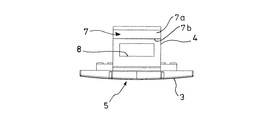
図1〜図7は本発明を実施する形態の一例であって、図中、図8と同一の符号を付した部分は同一物を表わしており、コネクタキャップ5の舌片4に屈曲凸部7と係止開口部8とを備えると共に、前記舌片4が挿入される端末装置本体1内における前記屈曲凸部7と対向する一方の面9及び該一方の面9に対向する他方の面10にそれぞれ抜止用突出部11,12を備え、該各抜止用突出部11,12は、前記コネクタキャップ5を端末装置本体1から引き出して前記一方の抜止用突出部11に前記屈曲凸部7が係止されたときに、前記他方の抜止用突出部12に前記係止開口部8の端縁が係止されるよう配置され、且つ前記各抜止用突出部11,12のコネクタユニット用開口2側の面が傾斜面11a,12aとなるようにしたものである。
FIGS. 1-7 is an example of the form which implements this invention, The part which attached | subjected the code | symbol same as FIG. 8 in the figure represents the same thing, and it is a bending convex part on the
前記コネクタキャップ5のキャップ本体3は、端末装置本体1のコネクタユニット用開口2と同形の略矩形板状をなし、コネクタユニット6の閉塞時にはキャップ本体3がコネクタユニット用開口2に嵌合するようになっている。
The
前記舌片4は、キャップ本体3の一方の長辺中央付近より突出するように設けられており、その先端に前記屈曲凸部7を有すると共に、この屈曲凸部7とキャップ本体3との間に係止開口部8を形成してある。
The
前記屈曲凸部7は、舌片4の先端側からキャップ本体3側へ向けて緩い傾斜角度で突出してその断面形状が傾斜面7aと舌片4に垂直な平面7bとからなる「∠」形状となるようにしてある。
The bent
前記係止開口部8はその正面から見た形状が長方形をなしコネクタキャップ5を端末装置本体1に取り付けたとき抜止用突出部12が係止開口部8内に配されるようになっている。
The
前記コネクタキャップ5の材質としては、例えば、常温でゴム状の弾性を有する高分子物質であるエラストマやポリプロピレン樹脂等の弾性部材が用いられているが、前記コネクタキャップ5の舌片4の係止開口部8を構成する両側の枠部分(図4の斜線部A参照)には、コネクタキャップ5を構成するエラストマ等の弾性部材より変形しにくい材質、例えば、ABS樹脂(Acrylonitrile Butadiene Styrene Resin:アクリロニトリル・ブタジエン・スチレン樹脂)やポリプロピレン樹脂、或いは金属等を成形時に予め組み込むように配置し、前記コネクタキャップ5の舌片4の係止開口部8を構成する両側の枠部分における剛性を高め、前記コネクタキャップ5の端末装置本体1に対する取付時に舌片4を挿入する際、該舌片4が変形しにくくなるようにしてある。
As the material of the
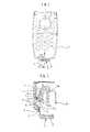
尚、図6及び図7に示す端末装置では、前記舌片4が挿入される端末装置本体1内における屈曲凸部7に対向する一方の面9を端末装置本体1の内壁とし、前記一方の面9に対向する他方の面10をコネクタユニット6の表面としてあり、このように舌片4が挿入される孔を端末装置本体1の内壁とコネクタユニット6の表面とで形成することにより、端末装置本体1の厚み幅を小さくできる点で利点がある。但し、端末装置本体1の厚み幅をそれ程小さくする必要がない場合には、コネクタユニット6の上部に前記舌片4が挿入される専用の壁を設け、この専用壁と前記端末装置本体1の内壁とで前記舌片4が挿入される孔を形成しても構わない。
In the terminal device shown in FIGS. 6 and 7, one
前記抜止用突出部11は、一方の面9より突出して設けられ、コネクタユニット用開口2側の面を傾斜面11aとすると共に、コネクタユニット用開口2と反対側の面を一方の面9に垂直な平面11bとし、その先端が先細り状となるように形成してある。
The
又、前記抜止用突出部12は、抜止用突出部11と同様に他方の面10(コネクタユニット6の表面)より突出して設けられ、コネクタユニット用開口2側の面を傾斜面12aとすると共に、コネクタユニット用開口2と反対側の面を他方の面10に垂直な平面12bとし、その先端が先細り状となるように形成してある。
Further, the retaining
次に、上記図示例の作用を説明する。 Next, the operation of the illustrated example will be described.
端末装置本体1を組み立てた後、該端末装置本体1にコネクタキャップ5を取り付ける際には、先ず、図5に示す状態から、図6(a),(b)に示す如く、前記コネクタキャップ5の舌片4をコネクタユニット用開口2から挿入すると、屈曲凸部7の傾斜面7aと一方の面9に形成された抜止用突出部11の傾斜面11aとが干渉し且つ屈曲凸部7の凹んでいる裏面側と他方の面10に形成された抜止用突出部12とが干渉するが、前記屈曲凸部7は舌片4の先端側からキャップ本体3側へ向け緩い傾斜角度で突出してその断面形状が「∠」形状となるようにしてあると共に、前記各抜止用突出部11,12のコネクタユニット用開口2側の面はそれぞれ傾斜面11a,12aとなるようにしてあり、更に前記コネクタキャップ5はエラストマ等の弾性部材で形成されているため、屈曲凸部7は弾性変形しつつ比較的容易に前記各抜止用突出部11,12を乗り越える形となり、しかも、前記コネクタキャップ5の舌片4の係止開口部8を構成する両側の枠部分(図4の斜線部A参照)には、コネクタキャップ5を構成するエラストマ等の弾性部材より変形しにくい材質を成形時に予め組み込むように配置し、前記コネクタキャップ5の舌片4の係止開口部8を構成する両側の枠部分における剛性を高めるようにしてあるため、前記コネクタキャップ5の端末装置本体1に対する取付時に舌片4を挿入する際、該舌片4は変形しにくくなり、その挿入作業が容易且つ確実に行えることとなる。
When the
そして、コネクタキャップ5の屈曲凸部7が抜止用突出部11を乗り越えると共に、抜止用突出部12がコネクタキャップ5の係止開口部8内に配置されることにより、コネクタキャップ5の端末装置本体1に対する取付が完了する。
Then, the bent
前記コネクタキャップ5の端末装置本体1に対する取付を完了した後、コネクタユニット用開口2をコネクタキャップ5で閉止した状態から、コネクタユニット6を使用するために、コネクタキャップ5を開けてその舌片4の部分を端末装置本体1内から引き出した場合、キャップ本体3が所定の距離だけ引き出されると、図7(a),(b)に示す如く、一方の抜止用突出部11の平面11bに屈曲凸部7の平面7bが係止されると共に、他方の抜止用突出部12の平面12bに係止開口部8の端面が当接して係止され、二重にロックされる形となるため、ユーザーが所定の距離より更にコネクタキャップ5を摘んで引っ張ったとしても、該コネクタキャップ5は端末装置本体1から外れることがなく、紛失してしまう心配がなくなる。
After the attachment of the
このように、本発明のコネクタのキャップ構造を用いれば、端末装置本体1の組立時における作業手順と関係なくコネクタキャップ5を取り付けることができ、且つ取付後は外れにくくその紛失を防止し得る。そのため、本発明の端末装置によれば、組立作業性を向上させることができると共に、コネクタキャップ5の紛失の虞のない端末装置を提供することができる。
As described above, when the connector cap structure of the present invention is used, the
尚、本発明のコネクタのキャップ構造及びこれを用いた端末装置は、上述の図示例にのみ限定されるものではなく、例えば、本実施形態では抜止用突出部11,12のコネクタユニット用開口2側の面を傾斜面11a,12aとしたが、曲面等のように舌片4の挿入を可能とする形状であれば良い。このように、本発明の要旨を逸脱しない範囲内において種々変更を加え得ることができることは言うまでもない。
The connector cap structure and the terminal device using the same according to the present invention are not limited to the above illustrated examples. For example, in this embodiment, the
1 端末装置本体
2 コネクタユニット用開口
3 キャップ本体
4 舌片
5 コネクタキャップ
6 コネクタユニット
7 屈曲凸部
8 係止開口部
9 一方の面
10 他方の面
11 抜止用突出部
12 抜止用突出部
DESCRIPTION OF
Claims (4)
前記コネクタキャップの舌片には屈曲凸部と係止開口部とを備えると共に、前記舌片が挿入される端末装置本体内における前記屈曲凸部と対向する一方の面及び該一方の面に対向する他方の面にはそれぞれ抜止用突出部を備え、該各抜止用突出部は、前記コネクタキャップを端末装置本体から引き出して前記一方の抜止用突出部に前記屈曲凸部が係止されたときに、前記他方の抜止用突出部に前記係止開口部の端縁が係止されるよう配置され、且つ前記各抜止用突出部のコネクタユニット用開口側の面がそれぞれ曲面又は傾斜面であることを特徴とするコネクタのキャップ構造。 A terminal device body, a cap body capable of opening and closing a connector unit opening formed in the terminal device body, and a tongue piece formed integrally with the cap body and removably inserted into the terminal device body. In the connector cap structure consisting of a connector cap composed of an elastic member,
The tongue piece of the connector cap includes a bent convex portion and a locking opening, and faces one surface facing the bent convex portion and the one surface in the terminal device body into which the tongue piece is inserted. The other surface is provided with a retaining protrusion, and each of the retaining protrusions is formed when the connector cap is pulled out from the terminal device body and the bent protrusion is locked to the one retaining protrusion. Are arranged so that the edge of the locking opening is locked to the other locking protrusion, and the surface of the locking protrusion on the connector unit opening side is a curved surface or an inclined surface, respectively. A connector cap structure characterized by that.
Priority Applications (1)
| Application Number | Priority Date | Filing Date | Title |
|---|---|---|---|
| JP2004103121A JP2005294936A (en) | 2004-03-31 | 2004-03-31 | Connector cap structure and terminal device employing the same |
Applications Claiming Priority (1)
| Application Number | Priority Date | Filing Date | Title |
|---|---|---|---|
| JP2004103121A JP2005294936A (en) | 2004-03-31 | 2004-03-31 | Connector cap structure and terminal device employing the same |
Publications (1)
| Publication Number | Publication Date |
|---|---|
| JP2005294936A true JP2005294936A (en) | 2005-10-20 |
Family
ID=35327430
Family Applications (1)
| Application Number | Title | Priority Date | Filing Date |
|---|---|---|---|
| JP2004103121A Pending JP2005294936A (en) | 2004-03-31 | 2004-03-31 | Connector cap structure and terminal device employing the same |
Country Status (1)
| Country | Link |
|---|---|
| JP (1) | JP2005294936A (en) |
Cited By (4)
| Publication number | Priority date | Publication date | Assignee | Title |
|---|---|---|---|---|
| JP2008011059A (en) * | 2006-06-28 | 2008-01-17 | Casio Hitachi Mobile Communications Co Ltd | Portable electronic equipment |
| JP2008294767A (en) * | 2007-05-24 | 2008-12-04 | Kyocera Corp | Portable electronic device |
| JP2009105618A (en) * | 2007-10-23 | 2009-05-14 | Nec Saitama Ltd | Mounting structure of terminal cover of terminal device, and terminal device provided with the same |
| JP2013080995A (en) * | 2011-09-30 | 2013-05-02 | Toshiba Corp | Electronic apparatus |
-
2004
- 2004-03-31 JP JP2004103121A patent/JP2005294936A/en active Pending
Cited By (4)
| Publication number | Priority date | Publication date | Assignee | Title |
|---|---|---|---|---|
| JP2008011059A (en) * | 2006-06-28 | 2008-01-17 | Casio Hitachi Mobile Communications Co Ltd | Portable electronic equipment |
| JP2008294767A (en) * | 2007-05-24 | 2008-12-04 | Kyocera Corp | Portable electronic device |
| JP2009105618A (en) * | 2007-10-23 | 2009-05-14 | Nec Saitama Ltd | Mounting structure of terminal cover of terminal device, and terminal device provided with the same |
| JP2013080995A (en) * | 2011-09-30 | 2013-05-02 | Toshiba Corp | Electronic apparatus |
Similar Documents
| Publication | Publication Date | Title |
|---|---|---|
| JP2642083B2 (en) | Switch board holding structure for small electronic equipment | |
| JP2006059659A (en) | Socket for memory card | |
| JP2005228756A (en) | Terminal cover protector structure for electronic apparatus, and terminal cover protector packaging method | |
| EP2706830A2 (en) | Cover and casing provided with a cover | |
| JP2018195594A (en) | Connector connection component for vehicle | |
| JP5091056B2 (en) | Closed container lid seal structure | |
| JP2007157779A (en) | Packing and electronic device | |
| JP2008164085A (en) | Clip | |
| JP2005294936A (en) | Connector cap structure and terminal device employing the same | |
| JP2006038157A (en) | Member fitting structure | |
| JPH10208806A (en) | Waterproof connector | |
| JP5345085B2 (en) | Cap structure | |
| JP4925472B2 (en) | Mobile device | |
| JP2004165851A (en) | Mobile radio terminal device | |
| JP4558439B2 (en) | Small electronic equipment | |
| JPH05275868A (en) | Housing for electric device | |
| JP2007180278A (en) | Fixing structure of escutcheon | |
| JP2014093453A (en) | Electronic apparatus | |
| JP2004146181A (en) | Waterproof connector | |
| JP4663339B2 (en) | Cover component and electronic device using the cover component | |
| JP2005184590A (en) | Loudspeaker mounting apparatus | |
| JP3889675B2 (en) | Compressor terminal protector | |
| JP4580703B2 (en) | Locking structure | |
| JP2007063904A (en) | Lock mechanism | |
| JP3936531B2 (en) | Grommet mating structure |
Legal Events
| Date | Code | Title | Description |
|---|---|---|---|
| A621 | Written request for application examination |
Effective date: 20070213 Free format text: JAPANESE INTERMEDIATE CODE: A621 |
|
| A977 | Report on retrieval |
Free format text: JAPANESE INTERMEDIATE CODE: A971007 Effective date: 20090129 |
|
| A131 | Notification of reasons for refusal |
Free format text: JAPANESE INTERMEDIATE CODE: A131 Effective date: 20090224 |
|
| A02 | Decision of refusal |
Free format text: JAPANESE INTERMEDIATE CODE: A02 Effective date: 20090804 |