EP2706830A2 - Cover and casing provided with a cover - Google Patents
Cover and casing provided with a cover Download PDFInfo
- Publication number
- EP2706830A2 EP2706830A2 EP20130195036 EP13195036A EP2706830A2 EP 2706830 A2 EP2706830 A2 EP 2706830A2 EP 20130195036 EP20130195036 EP 20130195036 EP 13195036 A EP13195036 A EP 13195036A EP 2706830 A2 EP2706830 A2 EP 2706830A2
- Authority
- EP
- European Patent Office
- Prior art keywords
- case
- cover
- hook
- protective cover
- flat plate
- Prior art date
- Legal status (The legal status is an assumption and is not a legal conclusion. Google has not performed a legal analysis and makes no representation as to the accuracy of the status listed.)
- Withdrawn
Links
- 230000001681 protective effect Effects 0.000 description 90
- 230000037431 insertion Effects 0.000 description 8
- 238000003780 insertion Methods 0.000 description 8
- 230000000717 retained effect Effects 0.000 description 2
- 238000004519 manufacturing process Methods 0.000 description 1
- 238000000465 moulding Methods 0.000 description 1
Images


Classifications
-
- H—ELECTRICITY
- H05—ELECTRIC TECHNIQUES NOT OTHERWISE PROVIDED FOR
- H05K—PRINTED CIRCUITS; CASINGS OR CONSTRUCTIONAL DETAILS OF ELECTRIC APPARATUS; MANUFACTURE OF ASSEMBLAGES OF ELECTRICAL COMPONENTS
- H05K5/00—Casings, cabinets or drawers for electric apparatus
- H05K5/02—Details
- H05K5/03—Covers
-
- H—ELECTRICITY
- H05—ELECTRIC TECHNIQUES NOT OTHERWISE PROVIDED FOR
- H05K—PRINTED CIRCUITS; CASINGS OR CONSTRUCTIONAL DETAILS OF ELECTRIC APPARATUS; MANUFACTURE OF ASSEMBLAGES OF ELECTRICAL COMPONENTS
- H05K5/00—Casings, cabinets or drawers for electric apparatus
- H05K5/02—Details
- H05K5/0217—Mechanical details of casings
-
- Y—GENERAL TAGGING OF NEW TECHNOLOGICAL DEVELOPMENTS; GENERAL TAGGING OF CROSS-SECTIONAL TECHNOLOGIES SPANNING OVER SEVERAL SECTIONS OF THE IPC; TECHNICAL SUBJECTS COVERED BY FORMER USPC CROSS-REFERENCE ART COLLECTIONS [XRACs] AND DIGESTS
- Y10—TECHNICAL SUBJECTS COVERED BY FORMER USPC
- Y10T—TECHNICAL SUBJECTS COVERED BY FORMER US CLASSIFICATION
- Y10T292/00—Closure fasteners
- Y10T292/68—Keepers
- Y10T292/696—With movable dog, catch or striker
- Y10T292/702—Pivoted or swinging
Definitions
- This invention relates to an electronic device, such as a digital camera or a portable music player.
- a memory card In an electronic device, such as a digital camera or a portable music player, a memory card is used. In recent years, the memory card is also used in some mobile phones. In order to enable the use of the memory card, the electronic device has a memory card connector mounted therein. The memory card connector is covered by a protective cover. When the memory card is inserted into or removed from the memory card connector, the protective cover is opened.
- the electronic device of this type having the protective cover is disclosed in, for example, Japanese Unexamined Patent Application Publication (JP-A) No. 2003-218549 .
- JP-A Japanese Unexamined Patent Application Publication
- Fig. 1 the electronic device will briefly be described.
- the electronic device includes an upper case 1, a lower case 2, and a protective cover 5.
- a panel 3 is provided and a memory card connector (not shown) is mounted on the panel 3.
- a memory card (not shown) can be inserted into or removed from the memory card connector.
- the protective cover 5 has a rectangular shape in plan view and a generally L shape in section.
- the protective cover 5 has insertion ribs 51 formed on both ends of a long side edge and generally L-shaped hooks 54 formed in the vicinity of both ends of short side edges.
- the upper case 1 has hook receivers 14 formed inside one long side in correspondence to the hooks 54 of the protective cover 5, respectively. Between the hooks 54 and an inner upper end of the lower case 2, a space S is formed.
- the hooks 54 of the protective cover 5 are elastically deformed in a direction perpendicular to a rotation center line (a line connecting the both insertion ribs 51) of the protective cover 5, so that the protective cover 5 is easy to be unintentionally opened from the upper case 1 when touched by hand.
- an electronic device characterized by including a case, a component connecting portion mounted inside the case, and a protective cover mounted to the case to be rotatable around a rotation center line and covering the component connecting portion, the protective cover having an elastically deformable hook facing a direction parallel to the rotation center line, the case having a hook receiver engageable with and disengageable from the hook.
- the electronic device may be arranged so that the case includes an upper case and a lower case coupled with the upper case, the protective cover and the hook receiver being disposed on the upper case.
- the electronic device may be arranged so that the case includes an upper case and a lower case coupled with the upper case, the protective cover being disposed on the upper case, the hook receiver being disposed on the lower case.
- the electronic device may be arranged so that the electronic device further including a panel arranged inside the case, the component connecting portion being mounted on the panel.
- the electronic device may be arranged so that the protective cover has an additional hook facing a direction reverse to the hooks, the case having an additional hook receiver engageable with and disengageable from the additional hook.
- the electronic device may be arranged so that the case has an edge portion formed on its upper surface and defining a cover receiving opening, the protective cover being mounted so as to be fitted to the cover receiving opening.
- the electronic device may be arranged so that the case has a flange formed on the edge portion, the protective cover being supported by the flange.
- the electronic device may be arranged so that the component connecting portion is a connector for connecting a memory card.
- the electronic device may be arranged so that the component connecting portion is a connector for connecting an SIM card.
- the electronic device may be arranged so that the component connecting portion is a contact point for connecting an exchangeable battery.
- a casing for an electronic device characterized by including a case incorporating a component connecting portion and a protective cover mounted to the case to be rotatable around a rotation center line and covering the component connecting portion, the protective cover having an elastically deformable hook facing a direction parallel to the rotation center line, the case having a hook receiver engageable with and disengageable from the hook.
- the casing may be arranged so that the case includes an upper case and a lower case coupled with the upper case, the protective cover and the hook receiver being disposed on the upper case.
- the casing may be arranged so that the case includes an upper case and a lower case coupled with the upper case, the protective cover being disposed on the upper case, the hook receiver being disposed on the lower case.
- the casing may be arranged so as to further include a panel arranged inside the case, the component connecting portion being mounted on the panel.
- the casing may be arranged so that the protective cover has an additional hook facing a direction reverse to the hooks, the case having an additional hook receiver engageable with and disengageable from the additional hook.
- the casing may be arranged so that the case has an edge portion formed on its upper surface and defining a cover receiving opening, the protective cover being mounted so as to be fitted to the cover receiving opening.
- the casing may be arranged so that the case has a flange formed on the edge portion, the protective cover being supported by the flange.
- the casing may be arranged so that the component connecting portion is a connector for connecting a memory card.
- the casing may be arranged so that the component connecting portion is a connector for connecting an SIM card.
- the casing may be arranged so that the component connecting portion is a contact point for connecting an exchangeable battery.
- the electronic device includes a case including an upper case 1 and a lower case 2 coupled thereto.
- the upper case 1 is provided with a protective cover 5.
- a circuit board or a panel 3 is provided between the upper case 1 and the lower case 2.
- a combination of the upper case 1, the lower case 2, the panel 3, and the protective cover 5 is called a casing for an electronic device.
- a memory card connector 31 is mounted as a component connecting portion.
- a memory card 4 can be inserted into or removed from the memory card connector 31.
- an internal mechanism (not shown in the figure) for a mobile phone, a digital camera, or a portable music player is provided by the use of the panel 3 or the like.
- the protective cover 5 has a rectangular shape extended in a first direction (left-to-right direction) A1 and in a second direction (back-and-forth direction) A2 perpendicular to the first direction.
- the protective cover 5 has a generally L-shaped section along a plane perpendicular to the first direction A.
- the protective cover 5 has, at an end portion in the second direction A2, i.e., at a rear end, a pair of insertion ribs 51 separated from each other in the first direction A1
- the protective cover 5 has, at its front end, a pair of hooks 52 separated from each other in the first direction A1. As apparent from Fig. 5 , both of the hooks 52 are formed to face outward in the first direction A1.
- the protective cover 5 is provided with a concave portion 53 at the center of the front end.
- the upper case 1 has an edge portion 1 a defining a cover receiving opening 12 which has a shape substantially congruent with that of the protective cover 5.
- the cover receiving opening 12 extends from an upper surface to a front surface of the upper case 1.
- the edge portion 1 a is provided with a flange 13 formed at its rear side.
- the protective cover 5 is mounted so as to be fitted to the cover receiving opening 12. In this event, the protective cover 5 is supported by the flange 13 to be prevented from dropping into the case through the cover receiving opening 12.
- the edge portion 1 a of the upper case 1 has, at its front side, hook holes 11 separated from each other in the first direction A1 and formed in one-to-one correspondence to the hooks 52.
- Each of the hook holes 11 is provided with a hook receiver 11 a formed at its inner part.
- the hook receivers 11 a are formed to face inward in the first direction A1 so as to be engaged with the hooks 52, respectively.
- the memory card 4 in a state shown in Fig. 3 is inserted into the memory card connector 31.
- the insertion ribs 51 of the protective cover 5 are engaged with an inner surface of a rear part of the edge portion 1 a of the upper case 1.
- the protective cover 5 is rotated rightward around the insertion ribs 51 by approximately 90 degrees toward a position shown in Fig. 2 to close the protective cover 5.
- a straight line connecting the insertion ribs 51 is a rotation center line of the protective cover 5. Therefore, this rotation center line extends in the first direction A1.
- the hooks 52 of the protective cover 5 are inserted into the hook holes 11 of the upper case 1, respectively.
- the hooks 52 of the protective cover 5 are slightly bent inward in the first direction A1 and go over convex portions 11 b to be engaged with the hook receivers 11a, respectively.
- the protective cover 5 in a closed state is firmly retained by the upper case 1.
- FIG. 7 an electronic device according to a second embodiment of the present invention will be described. Similar portions are designated by the like reference numerals and description thereof is omitted.
- the upper case 1 shown in Fig. 7 does not have those components corresponding to the hook holes 11 and the hook receivers 11a of the electronic device shown in Figs. 2 through 6 . Instead, on a front surface of the lower case 2, a pair of hook grooves 21 separated from each other in the first direction A1 and hook receivers 21a formed outside thereof and projecting forward are formed. As a matter of course, each set of the hook groove 21 and the hook receiver 21 is disposed in correspondence to each of the hooks 52 of the protective cover 5.
- the cover receiving opening 12 of the upper case 1 has a simplified structure. Further, a molding die used in manufacturing the upper case 1 can be simplified.
- the protective cover 5 can be completely separated from the upper case 1.
- the protective cover 5 may be loosely connected to the upper case 1 by a rubber component or the like.
- FIG. 8 through 10 an electronic device according to a third embodiment of the present invention will be described. Similar components are designated by the same reference numerals and description thereof is omitted.
- the protective cover 5 is connected to the upper case 1 by a connecting member 6 made of rubber having flexibility. Therefore, in this case, it may be said that the protective cover 5 is an openable/closable cover.
- the upper case 1 has a stopper portion 13 formed on a lower surface thereof.
- the protective cover 5 has a projection 54 formed on a lower surface thereof.
- the connecting member 6 generally has a U shape and includes a fixed portion 61 fixed to the projection 54 of the protective cover 5 and a pair of leg portions 62 extending in parallel with each other from the fixed portion 61.
- Each of the leg portions 62 has an engaging portion 63 to be engaged with the stopper portion 13 of the upper case 1 in the first direction A2.
- the engaging portions 63 are preferably separated from the stopper portion 13.
- the hooks 52 are released from the upper case 1 and the protective cover 5 is slightly moved forward in the second direction A2 and raised along a third direction (vertical direction) A3 perpendicular to the first direction A1 and the second direction A2. Consequently, the protective cover 5 can easily be opened. Incidentally, an operation of closing the protective cover 5 is carried out in a manner similar to the electronic device shown in Figs. 2 through 6 .
- the protective cover 5 is connected to the upper case 1 in a relatively loose state to be prevented from disengagement. Therefore, upon opening and closing the protective cover 5, usability is good.
- Each of the above-mentioned electronic devices has two sets of combination of the hook and the hook receiver but may be modified into a configuration with only one set. Further, in the foregoing, the case of using the memory card has been described. However, not being limited to the memory card, this invention is also applicable to a case where an SIM card or an exchangeable battery is used. In case where the SIM card is used, an SIM card connector is used as the component connecting portion. In case where the exchangeable battery is used, a contact point for connecting the battery is used as the component connecting portion.
- the case includes an upper case and a lower case coupled with the upper case, the protective cover and the hook receiver being disposed on the upper case, or the case includes an upper case and a lower case coupled with the upper case, the protective cover being disposed on the upper case, the hook receiver being disposed on the lower case.
- the electronic device further includes a panel arranged inside the case, the component connecting portion being mounted on the panel.
- the protective cover has an additional hook facing a direction reverse to the hooks, the case having an additional hook receiver engageable with and disengageable from the additional hook, and/or the case has an edge portion formed on its upper surface and defining a cover receiving opening, the protective cover being mounted so as to be fitted to the cover receiving opening, and/or the case has a flange formed on the edge portion, the protective cover being supported by the flange.
- the component connecting portion is a connector for connecting a memory card, the component connecting portion is a connector for connecting an SIM card, or the component connecting portion is a contact point for connecting an exchangeable battery.
- a casing for an electronic device includes a case incorporating a component connecting portion and a protective cover mounted to the case to be rotatable around a rotation center line and covering the component connecting portion, the protective cover having an elastically deformable hook facing a direction parallel to the rotation center line, the case having a hook receiver engageable with and disengageable from the hook.
- the case includes an upper case and a lower case coupled with the upper case, the protective cover and the hook receiver being disposed on the upper case, or the case includes an upper case and a lower case coupled with the upper case, the protective cover being disposed on the upper case, the hook receiver being disposed on the lower case.
- the casing for an electronic device further includes a panel arranged inside the case, the component connecting portion being mounted on the panel.
- the protective cover has an additional hook facing a direction reverse to the hooks, the case having an additional hook receiver engageable with and disengageable from the additional hook, and/or the case has an edge portion formed on its upper surface and defining a cover receiving opening, the protective cover being mounted so as to be fitted to the cover receiving opening, and/or the case has a flange formed on the edge portion, the protective cover being supported by the flange.
- the component connecting portion is a connector for connecting a memory card, the component connecting portion is a connector for connecting an SIM card, or the component connecting portion is a contact point for connecting an exchangeable battery.
Landscapes
- Engineering & Computer Science (AREA)
- Microelectronics & Electronic Packaging (AREA)
- Casings For Electric Apparatus (AREA)
- Telephone Set Structure (AREA)
- Details Of Rigid Or Semi-Rigid Containers (AREA)
Abstract
Description
- This invention relates to an electronic device, such as a digital camera or a portable music player.
- In an electronic device, such as a digital camera or a portable music player, a memory card is used. In recent years, the memory card is also used in some mobile phones. In order to enable the use of the memory card, the electronic device has a memory card connector mounted therein. The memory card connector is covered by a protective cover. When the memory card is inserted into or removed from the memory card connector, the protective cover is opened.
- The electronic device of this type having the protective cover is disclosed in, for example, Japanese Unexamined Patent Application Publication (JP-A) No.
2003-218549 Fig. 1 , the electronic device will briefly be described. - The electronic device includes an
upper case 1, alower case 2, and aprotective cover 5. In a space between theupper case 1 and thelower case 2, apanel 3 is provided and a memory card connector (not shown) is mounted on thepanel 3. A memory card (not shown) can be inserted into or removed from the memory card connector. - The
protective cover 5 has a rectangular shape in plan view and a generally L shape in section. Theprotective cover 5 hasinsertion ribs 51 formed on both ends of a long side edge and generally L-shaped hooks 54 formed in the vicinity of both ends of short side edges. - The
upper case 1 hashook receivers 14 formed inside one long side in correspondence to thehooks 54 of theprotective cover 5, respectively. Between thehooks 54 and an inner upper end of thelower case 2, a space S is formed. - When the
protective cover 5 is opened, an operation is performed as follows. First, a concave portion (not shown) formed on a right side surface of theprotective cover 5 inFig. 1 is pulled up by a finger. Consequently, thehooks 54 are disengaged from thehooks 14 of theupper case 1, respectively, and elastically deformed leftwards within a range of the space S. Subsequently, theprotective cover 5 is rotated around theinsertion ribs 51 in a direction shown by an arrow. Accordingly, theprotective cover 5 is opened, so that the memory card can be inserted into or removed from the memory card connector on thepanel 3. - In the above-mentioned electronic device, the
hooks 54 of theprotective cover 5 are elastically deformed in a direction perpendicular to a rotation center line (a line connecting the both insertion ribs 51) of theprotective cover 5, so that theprotective cover 5 is easy to be unintentionally opened from theupper case 1 when touched by hand. - In order to prevent the
protective cover 5 from being unintentionally opened from theupper case 1, it is inevitable to deepen a depth of engagement between thehooks 54 of theprotective cover 5 and thehooks 14 of theupper case 1. In this event, the space S inFig. 7 must be widened so that theupper case 1 and thelower case 2 are increased in size in a left-to-right [transversal] direction inFig. 7 . Thus, the electronic device itself is increased in size. - It is therefore an object of the present invention to provide an electronic device capable of preventing a protective cover from being unintentionally opened from a case and capable of achieving reduction in size.
- It is another object of the present invention to provide a casing for use in the above-mentioned electronic device.
- According to an aspect of the present invention, there is provided an electronic device characterized by including a case, a component connecting portion mounted inside the case, and a protective cover mounted to the case to be rotatable around a rotation center line and covering the component connecting portion, the protective cover having an elastically deformable hook facing a direction parallel to the rotation center line, the case having a hook receiver engageable with and disengageable from the hook.
- The electronic device may be arranged so that the case includes an upper case and a lower case coupled with the upper case, the protective cover and the hook receiver being disposed on the upper case.
- The electronic device may be arranged so that the case includes an upper case and a lower case coupled with the upper case, the protective cover being disposed on the upper case, the hook receiver being disposed on the lower case.
- The electronic device may be arranged so that the electronic device further including a panel arranged inside the case, the component connecting portion being mounted on the panel.
- The electronic device may be arranged so that the protective cover has an additional hook facing a direction reverse to the hooks, the case having an additional hook receiver engageable with and disengageable from the additional hook.
- The electronic device may be arranged so that the case has an edge portion formed on its upper surface and defining a cover receiving opening, the protective cover being mounted so as to be fitted to the cover receiving opening.
- The electronic device may be arranged so that the case has a flange formed on the edge portion, the protective cover being supported by the flange.
- The electronic device may be arranged so that the component connecting portion is a connector for connecting a memory card.
- The electronic device may be arranged so that the component connecting portion is a connector for connecting an SIM card.
- The electronic device may be arranged so that the component connecting portion is a contact point for connecting an exchangeable battery.
- According to another aspect of the present invention, there is provided a casing for an electronic device, characterized by including a case incorporating a component connecting portion and a protective cover mounted to the case to be rotatable around a rotation center line and covering the component connecting portion, the protective cover having an elastically deformable hook facing a direction parallel to the rotation center line, the case having a hook receiver engageable with and disengageable from the hook.
- The casing may be arranged so that the case includes an upper case and a lower case coupled with the upper case, the protective cover and the hook receiver being disposed on the upper case.
- The casing may be arranged so that the case includes an upper case and a lower case coupled with the upper case, the protective cover being disposed on the upper case, the hook receiver being disposed on the lower case.
- The casing may be arranged so as to further include a panel arranged inside the case, the component connecting portion being mounted on the panel.
- The casing may be arranged so that the protective cover has an additional hook facing a direction reverse to the hooks, the case having an additional hook receiver engageable with and disengageable from the additional hook.
- The casing may be arranged so that the case has an edge portion formed on its upper surface and defining a cover receiving opening, the protective cover being mounted so as to be fitted to the cover receiving opening.
- The casing may be arranged so that the case has a flange formed on the edge portion, the protective cover being supported by the flange.
- The casing may be arranged so that the component connecting portion is a connector for connecting a memory card.
- The casing may be arranged so that the component connecting portion is a connector for connecting an SIM card.
- The casing may be arranged so that the component connecting portion is a contact point for connecting an exchangeable battery.
-
-
Fig. 1 is a sectional view of a characteristic part of a conventional electronic device; -
Fig. 2 is a perspective view of an electronic device according to a first embodiment of the present invention; -
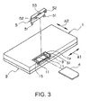
Fig. 3 is a perspective view of the electronic device together with a memory card in a state where a protective cover is removed therefrom; -
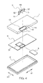
Fig. 4 is an exploded perspective view of the electronic device together with the memory card; -
Fig. 5 is a sectional view taken along a line V-V inFig. 2 ; -
Fig. 6 is a sectional view taken along a line VI-VI inFig. 2 ; -
Fig. 7 is an exploded perspective view of an electronic device, together with a memory card, according to a second embodiment of the present invention; -
Fig. 8 is a perspective view of an electronic device, together with a memory card, according to a third embodiment of the present invention in a state where a protective cover is removed therefrom; -
Fig. 9 is a schematic side view showing a state where the protective cover is opened; and -
Fig. 10 is a schematic bottom view of an upper cover showing a state where the protective cover is closed. - Referring to
Figs. 2 through 6 , an electronic device according to a first embodiment of the present invention will be described. - In
Figs. 2 through 6 , the electronic device includes a case including anupper case 1 and alower case 2 coupled thereto. Theupper case 1 is provided with aprotective cover 5. Inside the case, a circuit board or apanel 3 is provided between theupper case 1 and thelower case 2. Herein, a combination of theupper case 1, thelower case 2, thepanel 3, and theprotective cover 5 is called a casing for an electronic device. - On an upper surface of the
panel 3, amemory card connector 31 is mounted as a component connecting portion. Amemory card 4 can be inserted into or removed from thememory card connector 31. Inside the case, in addition to thememory card 4, an internal mechanism (not shown in the figure) for a mobile phone, a digital camera, or a portable music player is provided by the use of thepanel 3 or the like. - In plan view, the
protective cover 5 has a rectangular shape extended in a first direction (left-to-right direction) A1 and in a second direction (back-and-forth direction) A2 perpendicular to the first direction. Theprotective cover 5 has a generally L-shaped section along a plane perpendicular to the first direction A. Theprotective cover 5 has, at an end portion in the second direction A2, i.e., at a rear end, a pair ofinsertion ribs 51 separated from each other in the first direction A1 Further, theprotective cover 5 has, at its front end, a pair ofhooks 52 separated from each other in the first direction A1. As apparent fromFig. 5 , both of thehooks 52 are formed to face outward in the first direction A1. In addition, theprotective cover 5 is provided with aconcave portion 53 at the center of the front end. - The
upper case 1 has an edge portion 1 a defining acover receiving opening 12 which has a shape substantially congruent with that of theprotective cover 5. Thecover receiving opening 12 extends from an upper surface to a front surface of theupper case 1. The edge portion 1 a is provided with aflange 13 formed at its rear side. Theprotective cover 5 is mounted so as to be fitted to thecover receiving opening 12. In this event, theprotective cover 5 is supported by theflange 13 to be prevented from dropping into the case through thecover receiving opening 12. - The edge portion 1 a of the
upper case 1 has, at its front side, hook holes 11 separated from each other in the first direction A1 and formed in one-to-one correspondence to thehooks 52. Each of the hook holes 11 is provided with a hook receiver 11 a formed at its inner part. The hook receivers 11 a are formed to face inward in the first direction A1 so as to be engaged with thehooks 52, respectively. - The
memory card 4 in a state shown inFig. 3 is inserted into thememory card connector 31. Next, theinsertion ribs 51 of theprotective cover 5 are engaged with an inner surface of a rear part of the edge portion 1 a of theupper case 1. Subsequently, theprotective cover 5 is rotated rightward around theinsertion ribs 51 by approximately 90 degrees toward a position shown inFig. 2 to close theprotective cover 5. In this event, a straight line connecting theinsertion ribs 51 is a rotation center line of theprotective cover 5. Therefore, this rotation center line extends in the first direction A1. - When the
protective cover 5 is closed, thehooks 52 of theprotective cover 5 are inserted into the hook holes 11 of theupper case 1, respectively. Eventually, as shown inFigs. 5 and 6 , thehooks 52 of theprotective cover 5 are slightly bent inward in the first direction A1 and go overconvex portions 11 b to be engaged with the hook receivers 11a, respectively. Thus, as shown inFig. 2 , theprotective cover 5 in a closed state is firmly retained by theupper case 1. - In case where the
protective cover 5 is opened from the state ofFig. 2 , an operation is performed as follows. Theconcave portion 53 of theprotective cover 5 is pulled up by a finger engaged therewith. Then, thehooks 52 of theprotective cover 5 are disengaged from the hook receivers 11a of theupper case 1, respectively. Therefore, theprotective cover 5 can easily be opened. - Referring to
Fig. 7 , an electronic device according to a second embodiment of the present invention will be described. Similar portions are designated by the like reference numerals and description thereof is omitted. - The
upper case 1 shown inFig. 7 does not have those components corresponding to the hook holes 11 and the hook receivers 11a of the electronic device shown inFigs. 2 through 6 . Instead, on a front surface of thelower case 2, a pair ofhook grooves 21 separated from each other in the first direction A1 andhook receivers 21a formed outside thereof and projecting forward are formed. As a matter of course, each set of thehook groove 21 and thehook receiver 21 is disposed in correspondence to each of thehooks 52 of theprotective cover 5. - In this electronic device, when the
protective cover 5 is closed, thehooks 52 of theprotective cover 5 are inserted into thehook grooves 21 of thelower case 2, respectively. Thehooks 52 of theprotective cover 5 are engaged with thehook receivers 21 a in a vertical direction with slight inward bend in the first direction A1. Thus, theprotective cover 5 in a closed state is firmly retained by the case Incidentally, an operation of opening theprotective cover 5 is carried out in a manner similar to the electronic device shown inFigs. 2 through 6 . - According to the electronic device in
Fig. 7 , thecover receiving opening 12 of theupper case 1 has a simplified structure. Further, a molding die used in manufacturing theupper case 1 can be simplified. - In the electronic device shown in
Fig. 3 or7 , theprotective cover 5 can be completely separated from theupper case 1. However, for the sake of usability, theprotective cover 5 may be loosely connected to theupper case 1 by a rubber component or the like. - Referring to
Figs. 8 through 10 , an electronic device according to a third embodiment of the present invention will be described. Similar components are designated by the same reference numerals and description thereof is omitted. - In the electronic device shown in
Figs. 8 through 10 , theprotective cover 5 is connected to theupper case 1 by a connectingmember 6 made of rubber having flexibility. Therefore, in this case, it may be said that theprotective cover 5 is an openable/closable cover. - The
upper case 1 has astopper portion 13 formed on a lower surface thereof. Theprotective cover 5 has aprojection 54 formed on a lower surface thereof. The connectingmember 6 generally has a U shape and includes a fixedportion 61 fixed to theprojection 54 of theprotective cover 5 and a pair ofleg portions 62 extending in parallel with each other from the fixedportion 61. Each of theleg portions 62 has an engagingportion 63 to be engaged with thestopper portion 13 of theupper case 1 in the first direction A2. Thus, disengagement of theprotective cover 5 from theupper case 1 is prevented. In a state where theprotective cover 5 is normally mounted to theupper case 1, the engagingportions 63 are preferably separated from thestopper portion 13. - The
hooks 52 are released from theupper case 1 and theprotective cover 5 is slightly moved forward in the second direction A2 and raised along a third direction (vertical direction) A3 perpendicular to the first direction A1 and the second direction A2. Consequently, theprotective cover 5 can easily be opened. Incidentally, an operation of closing theprotective cover 5 is carried out in a manner similar to the electronic device shown inFigs. 2 through 6 . - According to the electronic device shown in
Figs. 8 through 10 , theprotective cover 5 is connected to theupper case 1 in a relatively loose state to be prevented from disengagement. Therefore, upon opening and closing theprotective cover 5, usability is good. - Each of the above-mentioned electronic devices has two sets of combination of the hook and the hook receiver but may be modified into a configuration with only one set. Further, in the foregoing, the case of using the memory card has been described. However, not being limited to the memory card, this invention is also applicable to a case where an SIM card or an exchangeable battery is used. In case where the SIM card is used, an SIM card connector is used as the component connecting portion. In case where the exchangeable battery is used, a contact point for connecting the battery is used as the component connecting portion.
- Exemplary embodiments of the present invention are as follows:
- According to one embodiment, an electronic device includes a case, a component connecting portion mounted inside the case, and a protective cover mounted to the case to be rotatable around a rotation center line and covering the component connecting portion, the protective cover having an elastically deformable hook facing a direction parallel to the rotation center line, the case having a hook receiver engageable with and disengageable from the hook.
- In other embodiments, the case includes an upper case and a lower case coupled with the upper case, the protective cover and the hook receiver being disposed on the upper case, or the case includes an upper case and a lower case coupled with the upper case, the protective cover being disposed on the upper case, the hook receiver being disposed on the lower case.
- According to another embodiment, the electronic device further includes a panel arranged inside the case, the component connecting portion being mounted on the panel.
- In other embodiments, the protective cover has an additional hook facing a direction reverse to the hooks, the case having an additional hook receiver engageable with and disengageable from the additional hook, and/or the case has an edge portion formed on its upper surface and defining a cover receiving opening, the protective cover being mounted so as to be fitted to the cover receiving opening, and/or the case has a flange formed on the edge portion, the protective cover being supported by the flange.
- In other embodiments, the component connecting portion is a connector for connecting a memory card, the component connecting portion is a connector for connecting an SIM card, or the component connecting portion is a contact point for connecting an exchangeable battery.
- According to yet another embodiment, a casing for an electronic device includes a case incorporating a component connecting portion and a protective cover mounted to the case to be rotatable around a rotation center line and covering the component connecting portion, the protective cover having an elastically deformable hook facing a direction parallel to the rotation center line, the case having a hook receiver engageable with and disengageable from the hook.
- In other embodiments, the case includes an upper case and a lower case coupled with the upper case, the protective cover and the hook receiver being disposed on the upper case, or the case includes an upper case and a lower case coupled with the upper case, the protective cover being disposed on the upper case, the hook receiver being disposed on the lower case.
- According to another embodiment, the casing for an electronic device further includes a panel arranged inside the case, the component connecting portion being mounted on the panel.
- In other embodiments, the protective cover has an additional hook facing a direction reverse to the hooks, the case having an additional hook receiver engageable with and disengageable from the additional hook, and/or the case has an edge portion formed on its upper surface and defining a cover receiving opening, the protective cover being mounted so as to be fitted to the cover receiving opening, and/or the case has a flange formed on the edge portion, the protective cover being supported by the flange.
- In other embodiments, the component connecting portion is a connector for connecting a memory card, the component connecting portion is a connector for connecting an SIM card, or the component connecting portion is a contact point for connecting an exchangeable battery.
- In order to realize easy insertion and removal of the memory card, the SIM card, or the exchangeable battery, a complicated lock mechanism using a spring is often used. However, by employing the present invention, the above-mentioned mechanism is unnecessary and reliability of the electronic device can be achieved by inexpensive alternative means.
Claims (15)
- A cover comprising:a first flat plate having two principal surfaces;a first hook projecting from a first end portion of the first flat plate towards a first direction parallel to the principal surfaces; anda first engagement portion projecting from a free end of the first hook in a second direction which is parallel to the principal surfaces and different from the first direction.
- The cover according to claim 1, further comprising:a second hook projecting from the first end portion towards the first direction; anda second engagement portion projecting from a free end of the second hook in the second direction.
- The cover according to claim 2, wherein the first and the second engagement portions are directed to reverse mutually in the second direction.
- The cover according to any one of claims 1 to 3, further comprising a second flat plate coupled to a second end portion of the first flat plate.
- The cover according to claim 4, further comprising an additional hook provided to an end portion of the second flat plate.
- The cover according to claim 4 or 5, wherein the second flat plate has a principal surface extending from the second end portion in a direction intersecting the principal surfaces of the first flat plate, and the second flat plate comprising a lib projecting, from an end portion opposite to the first flat plate, in a direction parallel to the principal surface of the second flat plate.
- A casing comprising:the cover according to any one of claims 1 to 3; anda case provided with the cover.
- The casing according to claim 7, wherein the cover is put on the case so that a flat surface including projection directions of the first hook and the first engagement portion faces an upper wall or a side wall of the case, and the case has a hook receiver for engaging the first engagement portion.
- The casing according to claim 7 or 8, wherein the cover further comprises a lib projecting from an end portion which is opposite to the first end portion.
- The casing according to claim 9, wherein the cover is rotatable around a rotation center line which is produced by engaging the lib with the case, and the first hook is provided at its end portion which is apart from the rotation center line.
- The casing according to any one of claims 7 to 10, wherein the case has a recess adapted to fit the first hook, and the hook receiver is formed on an end portion of the recess, and/or
wherein the case and the cover are connected to each other through a flexible material. - The casing according to any one of claims 7 to 11, further comprising:a second flat plate coupled to a second end portion of the first flat plate; andan additional hook provided to an end portion of the second flat plate,wherein the case further comprising an additional hook receiver adapted to be engaged with the additional hook.
- The casing according to any one of claims 7 to 12, wherein the case has an open portion, and the cover is placed over the open portion.
- The casing according to claim 13, wherein the case has a flange provided to at least a portion of a periphery of the open portion, the cover is placed on the flange.
- The casing according to claim 14, wherein the flange has a cutout portion for receiving the additional hook receiver.
Applications Claiming Priority (2)
| Application Number | Priority Date | Filing Date | Title |
|---|---|---|---|
| JP2005217292 | 2005-07-27 | ||
| EP06782214A EP1909547A4 (en) | 2005-07-27 | 2006-07-27 | Electronic device and casing used therefor |
Related Parent Applications (1)
| Application Number | Title | Priority Date | Filing Date |
|---|---|---|---|
| EP06782214A Division EP1909547A4 (en) | 2005-07-27 | 2006-07-27 | Electronic device and casing used therefor |
Publications (2)
| Publication Number | Publication Date |
|---|---|
| EP2706830A2 true EP2706830A2 (en) | 2014-03-12 |
| EP2706830A3 EP2706830A3 (en) | 2014-07-02 |
Family
ID=37683547
Family Applications (2)
| Application Number | Title | Priority Date | Filing Date |
|---|---|---|---|
| EP20130195036 Withdrawn EP2706830A3 (en) | 2005-07-27 | 2006-07-27 | Cover and casing provided with a cover |
| EP06782214A Ceased EP1909547A4 (en) | 2005-07-27 | 2006-07-27 | Electronic device and casing used therefor |
Family Applications After (1)
| Application Number | Title | Priority Date | Filing Date |
|---|---|---|---|
| EP06782214A Ceased EP1909547A4 (en) | 2005-07-27 | 2006-07-27 | Electronic device and casing used therefor |
Country Status (5)
| Country | Link |
|---|---|
| US (2) | US8995135B2 (en) |
| EP (2) | EP2706830A3 (en) |
| JP (2) | JP4968476B2 (en) |
| CN (2) | CN102802371A (en) |
| WO (1) | WO2007013672A1 (en) |
Families Citing this family (11)
| Publication number | Priority date | Publication date | Assignee | Title |
|---|---|---|---|---|
| JP5002552B2 (en) * | 2008-07-30 | 2012-08-15 | 三洋電機株式会社 | Electronics |
| JP5344969B2 (en) * | 2009-04-02 | 2013-11-20 | 株式会社ソニー・コンピュータエンタテインメント | Electronic device and hard disk device holder mounted thereon |
| CN101938537B (en) * | 2009-06-29 | 2013-10-09 | 深圳富泰宏精密工业有限公司 | Hanging ornament installation structure and portable electronic device with same |
| CN102340960A (en) * | 2010-07-26 | 2012-02-01 | 深圳富泰宏精密工业有限公司 | Chip card loading and unloading structure and electronic device thereof |
| CN102536771A (en) * | 2012-02-20 | 2012-07-04 | 上海航天科工电器研究院有限公司 | External type compressor protector |
| JP2015115511A (en) * | 2013-12-13 | 2015-06-22 | 株式会社シグマ | Connector panel |
| JP6448580B2 (en) * | 2016-05-31 | 2019-01-09 | 株式会社コンテック | Card retainer and computer |
| CN109714915A (en) * | 2017-10-25 | 2019-05-03 | 杭州疆域创新医疗科技有限公司 | Opening-closing structure and electronic device with the opening-closing structure |
| DE102018205765A1 (en) * | 2018-04-17 | 2019-10-17 | Volkswagen Aktiengesellschaft | Mounting arrangement of an electrically driven motor vehicle |
| US10665408B2 (en) * | 2018-06-01 | 2020-05-26 | Eaton Intelligent Power Limited | Electrical switching apparatus, maintaining system therefor, and associated maintaining method |
| ES3026222T3 (en) * | 2018-11-15 | 2025-06-10 | Lg Energy Solution Ltd | Battery pack case comprising hook coupling structure |
Citations (1)
| Publication number | Priority date | Publication date | Assignee | Title |
|---|---|---|---|---|
| JP2003218549A (en) | 2002-01-24 | 2003-07-31 | Matsushita Electric Ind Co Ltd | Cover device |
Family Cites Families (30)
| Publication number | Priority date | Publication date | Assignee | Title |
|---|---|---|---|---|
| JPS54184427U (en) * | 1978-06-20 | 1979-12-27 | ||
| US4844645A (en) * | 1988-02-29 | 1989-07-04 | Hewlett-Packard Company | Locking system |
| JPH0485656U (en) * | 1990-11-30 | 1992-07-24 | ||
| JPH077179A (en) | 1993-06-16 | 1995-01-10 | Sanyo Electric Co Ltd | Light emitting element |
| JP2569080Y2 (en) * | 1993-06-24 | 1998-04-22 | 矢崎総業株式会社 | Locking structure of removable cover |
| US5580182A (en) * | 1995-06-07 | 1996-12-03 | Inventec Corporation | Computer peripheral engagement/disengagement mechanism |
| JPH0918167A (en) * | 1995-06-26 | 1997-01-17 | Ando Electric Co Ltd | Drip-proof structure of rotary cover for housing |
| JP3382073B2 (en) * | 1995-09-19 | 2003-03-04 | 株式会社東芝 | Portable electronic devices |
| JPH1045152A (en) * | 1996-07-30 | 1998-02-17 | Kokusai Electric Co Ltd | Housing clamp structure |
| JPH10162796A (en) | 1996-11-28 | 1998-06-19 | Saitama Nippon Denki Kk | Battery pack fitting mechanism and fitting method |
| JPH11237930A (en) | 1998-02-20 | 1999-08-31 | Canon Inc | Portable electronic devices |
| JP2000228586A (en) | 1999-02-08 | 2000-08-15 | Teishin Denki Kk | Storage case for substrates, etc. |
| JP2001118554A (en) | 1999-10-19 | 2001-04-27 | Kyocera Corp | Battery lid lock mechanism |
| JP2002118634A (en) * | 2000-10-06 | 2002-04-19 | Matsushita Electric Ind Co Ltd | Information apparatus equipped with contact terminal |
| US7711400B2 (en) * | 2000-12-29 | 2010-05-04 | Vertu Limited | Casing |
| TW513885B (en) * | 2001-07-26 | 2002-12-11 | Benq Corp | Mobile phone having battery latch |
| US6674639B2 (en) * | 2001-09-06 | 2004-01-06 | High Tech Computer, Corp. | Protective cover with ternary structure |
| CN2504871Y (en) * | 2001-09-24 | 2002-08-07 | 英业达集团(南京)电子技术有限公司 | Electronic device with easy detaching cover |
| FR2836593B1 (en) * | 2002-02-28 | 2005-07-15 | Apem | MODULAR ELECTRICAL SWITCH AND ELECTRICAL SWITCHING DEVICE COMPRISING AT LEAST ONE SUCH SWITCH |
| CN2562222Y (en) * | 2002-06-24 | 2003-07-23 | 吴国征 | Host computer housing connected with common hard disc drive |
| JP2004031656A (en) * | 2002-06-26 | 2004-01-29 | Hioki Ee Corp | Lid locking mechanism |
| US20040198243A1 (en) * | 2002-08-13 | 2004-10-07 | Tony Tasy | Mobile phone with a replaceable face panel |
| KR100489985B1 (en) * | 2002-09-25 | 2005-05-17 | 삼성전자주식회사 | Locking device for battery pack in portable radiotelephone |
| JP3774828B2 (en) * | 2002-09-30 | 2006-05-17 | 日本電気株式会社 | Electronics |
| JP4121829B2 (en) * | 2002-10-25 | 2008-07-23 | 松下電器産業株式会社 | Lid device |
| JP2004214969A (en) * | 2002-12-27 | 2004-07-29 | Matsushita Electric Ind Co Ltd | Portable electronic devices |
| KR100469438B1 (en) * | 2003-03-25 | 2005-02-02 | 엘지전자 주식회사 | Battery cover locking apparatus for potable phone |
| JP4048157B2 (en) * | 2003-07-07 | 2008-02-13 | アルプス電気株式会社 | Electronic device cover mounting structure |
| KR100556886B1 (en) * | 2003-09-19 | 2006-03-03 | 엘지전자 주식회사 | Mobile terminal with camera position lock |
| CN2798517Y (en) * | 2005-06-10 | 2006-07-19 | 梅特勒-托利多仪器(上海)有限公司 | Cover plate with locking device for opening/closing shell window |
-
2006
- 2006-07-27 JP JP2007526944A patent/JP4968476B2/en not_active Expired - Fee Related
- 2006-07-27 CN CN2012102586761A patent/CN102802371A/en active Pending
- 2006-07-27 EP EP20130195036 patent/EP2706830A3/en not_active Withdrawn
- 2006-07-27 EP EP06782214A patent/EP1909547A4/en not_active Ceased
- 2006-07-27 CN CN2006800275703A patent/CN101233796B/en not_active Expired - Fee Related
- 2006-07-27 WO PCT/JP2006/315345 patent/WO2007013672A1/en not_active Ceased
- 2006-07-27 US US11/996,843 patent/US8995135B2/en active Active
-
2011
- 2011-08-15 JP JP2011177639A patent/JP5218799B2/en not_active Expired - Fee Related
-
2015
- 2015-03-27 US US14/671,440 patent/US20150201512A1/en not_active Abandoned
Patent Citations (1)
| Publication number | Priority date | Publication date | Assignee | Title |
|---|---|---|---|---|
| JP2003218549A (en) | 2002-01-24 | 2003-07-31 | Matsushita Electric Ind Co Ltd | Cover device |
Also Published As
| Publication number | Publication date |
|---|---|
| US20150201512A1 (en) | 2015-07-16 |
| JP5218799B2 (en) | 2013-06-26 |
| EP1909547A4 (en) | 2010-10-27 |
| CN102802371A (en) | 2012-11-28 |
| US20100142156A1 (en) | 2010-06-10 |
| JP4968476B2 (en) | 2012-07-04 |
| EP2706830A3 (en) | 2014-07-02 |
| EP1909547A1 (en) | 2008-04-09 |
| CN101233796B (en) | 2012-09-05 |
| CN101233796A (en) | 2008-07-30 |
| JPWO2007013672A1 (en) | 2009-02-12 |
| JP2012015533A (en) | 2012-01-19 |
| US8995135B2 (en) | 2015-03-31 |
| WO2007013672A1 (en) | 2007-02-01 |
Similar Documents
| Publication | Publication Date | Title |
|---|---|---|
| US20150201512A1 (en) | Electronic device and a casing used therefor | |
| US7500866B2 (en) | Lid with projections for covering an opening formed at a mobile communication terminal | |
| EP1574886B1 (en) | Receptacle with shutter for optical connector | |
| US8481200B2 (en) | Battery cover | |
| US20100084310A1 (en) | Chip card holder | |
| JP2023022448A (en) | Connector unit and cap | |
| JP4340088B2 (en) | Mobile device | |
| EP1691430A2 (en) | Electronic instrument | |
| JP4925472B2 (en) | Mobile device | |
| US8041408B2 (en) | Battery fastening apparatus and portable terminal using the same | |
| JP4558439B2 (en) | Small electronic equipment | |
| JP2018182158A (en) | Electronics | |
| JP2011259279A (en) | Portable electronic device | |
| JP4578509B2 (en) | Vehicle console panel | |
| JP2003125046A (en) | Terminal device | |
| US8779289B2 (en) | Electronic apparatus including lid opening and closing mechanism | |
| JPH10155014A (en) | Mobile phone | |
| JP4804124B2 (en) | Portable electronic devices | |
| US20040095325A1 (en) | Computer keyboard | |
| JP2747270B2 (en) | Battery storage device | |
| JP2013026999A (en) | Portable electronic equipment | |
| JP2005011693A (en) | Portable electronic devices | |
| KR20150000657A (en) | Cover opening/closing apparatus for electronic appliances | |
| JP2012015141A (en) | Cover opening/closing mechanism | |
| JP2011095981A (en) | Card mounting device |
Legal Events
| Date | Code | Title | Description |
|---|---|---|---|
| PUAI | Public reference made under article 153(3) epc to a published international application that has entered the european phase |
Free format text: ORIGINAL CODE: 0009012 |
|
| AC | Divisional application: reference to earlier application |
Ref document number: 1909547 Country of ref document: EP Kind code of ref document: P |
|
| AK | Designated contracting states |
Kind code of ref document: A2 Designated state(s): DE FR GB IT |
|
| PUAL | Search report despatched |
Free format text: ORIGINAL CODE: 0009013 |
|
| AK | Designated contracting states |
Kind code of ref document: A3 Designated state(s): DE FR GB IT |
|
| RIC1 | Information provided on ipc code assigned before grant |
Ipc: H05K 5/02 20060101AFI20140526BHEP Ipc: H04M 1/21 20060101ALI20140526BHEP Ipc: H04M 1/02 20060101ALI20140526BHEP |
|
| 17P | Request for examination filed |
Effective date: 20150105 |
|
| RBV | Designated contracting states (corrected) |
Designated state(s): DE FR GB IT |
|
| STAA | Information on the status of an ep patent application or granted ep patent |
Free format text: STATUS: THE APPLICATION HAS BEEN WITHDRAWN |
|
| 18W | Application withdrawn |
Effective date: 20180221 |